EP3573170B1 - Spannungsmessvorrichtung für die batteriezelle eines fahrzeugs - Google Patents
Spannungsmessvorrichtung für die batteriezelle eines fahrzeugs Download PDFInfo
- Publication number
- EP3573170B1 EP3573170B1 EP19168991.8A EP19168991A EP3573170B1 EP 3573170 B1 EP3573170 B1 EP 3573170B1 EP 19168991 A EP19168991 A EP 19168991A EP 3573170 B1 EP3573170 B1 EP 3573170B1
- Authority
- EP
- European Patent Office
- Prior art keywords
- voltage
- pair
- voltage measurement
- battery cell
- connection parts
- Prior art date
- Legal status (The legal status is an assumption and is not a legal conclusion. Google has not performed a legal analysis and makes no representation as to the accuracy of the status listed.)
- Active
Links
Images




Classifications
-
- H—ELECTRICITY
- H01—ELECTRIC ELEMENTS
- H01M—PROCESSES OR MEANS, e.g. BATTERIES, FOR THE DIRECT CONVERSION OF CHEMICAL ENERGY INTO ELECTRICAL ENERGY
- H01M10/00—Secondary cells; Manufacture thereof
- H01M10/42—Methods or arrangements for servicing or maintenance of secondary cells or secondary half-cells
- H01M10/48—Accumulators combined with arrangements for measuring, testing or indicating the condition of cells, e.g. the level or density of the electrolyte
-
- G—PHYSICS
- G01—MEASURING; TESTING
- G01R—MEASURING ELECTRIC VARIABLES; MEASURING MAGNETIC VARIABLES
- G01R31/00—Arrangements for testing electric properties; Arrangements for locating electric faults; Arrangements for electrical testing characterised by what is being tested not provided for elsewhere
- G01R31/36—Arrangements for testing, measuring or monitoring the electrical condition of accumulators or electric batteries, e.g. capacity or state of charge [SoC]
- G01R31/396—Acquisition or processing of data for testing or for monitoring individual cells or groups of cells within a battery
-
- H—ELECTRICITY
- H01—ELECTRIC ELEMENTS
- H01M—PROCESSES OR MEANS, e.g. BATTERIES, FOR THE DIRECT CONVERSION OF CHEMICAL ENERGY INTO ELECTRICAL ENERGY
- H01M10/00—Secondary cells; Manufacture thereof
- H01M10/42—Methods or arrangements for servicing or maintenance of secondary cells or secondary half-cells
- H01M10/4285—Testing apparatus
-
- B—PERFORMING OPERATIONS; TRANSPORTING
- B23—MACHINE TOOLS; METAL-WORKING NOT OTHERWISE PROVIDED FOR
- B23K—SOLDERING OR UNSOLDERING; WELDING; CLADDING OR PLATING BY SOLDERING OR WELDING; CUTTING BY APPLYING HEAT LOCALLY, e.g. FLAME CUTTING; WORKING BY LASER BEAM
- B23K26/00—Working by laser beam, e.g. welding, cutting or boring
- B23K26/34—Laser welding for purposes other than joining
-
- B—PERFORMING OPERATIONS; TRANSPORTING
- B60—VEHICLES IN GENERAL
- B60L—PROPULSION OF ELECTRICALLY-PROPELLED VEHICLES; SUPPLYING ELECTRIC POWER FOR AUXILIARY EQUIPMENT OF ELECTRICALLY-PROPELLED VEHICLES; ELECTRODYNAMIC BRAKE SYSTEMS FOR VEHICLES IN GENERAL; MAGNETIC SUSPENSION OR LEVITATION FOR VEHICLES; MONITORING OPERATING VARIABLES OF ELECTRICALLY-PROPELLED VEHICLES; ELECTRIC SAFETY DEVICES FOR ELECTRICALLY-PROPELLED VEHICLES
- B60L58/00—Methods or circuit arrangements for monitoring or controlling batteries or fuel cells, specially adapted for electric vehicles
- B60L58/10—Methods or circuit arrangements for monitoring or controlling batteries or fuel cells, specially adapted for electric vehicles for monitoring or controlling batteries
-
- G—PHYSICS
- G01—MEASURING; TESTING
- G01R—MEASURING ELECTRIC VARIABLES; MEASURING MAGNETIC VARIABLES
- G01R31/00—Arrangements for testing electric properties; Arrangements for locating electric faults; Arrangements for electrical testing characterised by what is being tested not provided for elsewhere
- G01R31/005—Testing of electric installations on transport means
-
- G—PHYSICS
- G01—MEASURING; TESTING
- G01R—MEASURING ELECTRIC VARIABLES; MEASURING MAGNETIC VARIABLES
- G01R31/00—Arrangements for testing electric properties; Arrangements for locating electric faults; Arrangements for electrical testing characterised by what is being tested not provided for elsewhere
- G01R31/36—Arrangements for testing, measuring or monitoring the electrical condition of accumulators or electric batteries, e.g. capacity or state of charge [SoC]
- G01R31/364—Battery terminal connectors with integrated measuring arrangements
-
- G—PHYSICS
- G01—MEASURING; TESTING
- G01R—MEASURING ELECTRIC VARIABLES; MEASURING MAGNETIC VARIABLES
- G01R31/00—Arrangements for testing electric properties; Arrangements for locating electric faults; Arrangements for electrical testing characterised by what is being tested not provided for elsewhere
- G01R31/36—Arrangements for testing, measuring or monitoring the electrical condition of accumulators or electric batteries, e.g. capacity or state of charge [SoC]
- G01R31/382—Arrangements for monitoring battery or accumulator variables, e.g. SoC
- G01R31/3835—Arrangements for monitoring battery or accumulator variables, e.g. SoC involving only voltage measurements
-
- H—ELECTRICITY
- H01—ELECTRIC ELEMENTS
- H01M—PROCESSES OR MEANS, e.g. BATTERIES, FOR THE DIRECT CONVERSION OF CHEMICAL ENERGY INTO ELECTRICAL ENERGY
- H01M10/00—Secondary cells; Manufacture thereof
- H01M10/42—Methods or arrangements for servicing or maintenance of secondary cells or secondary half-cells
- H01M10/425—Structural combination with electronic components, e.g. electronic circuits integrated to the outside of the casing
-
- B—PERFORMING OPERATIONS; TRANSPORTING
- B23—MACHINE TOOLS; METAL-WORKING NOT OTHERWISE PROVIDED FOR
- B23K—SOLDERING OR UNSOLDERING; WELDING; CLADDING OR PLATING BY SOLDERING OR WELDING; CUTTING BY APPLYING HEAT LOCALLY, e.g. FLAME CUTTING; WORKING BY LASER BEAM
- B23K2101/00—Articles made by soldering, welding or cutting
- B23K2101/36—Electric or electronic devices
- B23K2101/38—Conductors
-
- B—PERFORMING OPERATIONS; TRANSPORTING
- B60—VEHICLES IN GENERAL
- B60L—PROPULSION OF ELECTRICALLY-PROPELLED VEHICLES; SUPPLYING ELECTRIC POWER FOR AUXILIARY EQUIPMENT OF ELECTRICALLY-PROPELLED VEHICLES; ELECTRODYNAMIC BRAKE SYSTEMS FOR VEHICLES IN GENERAL; MAGNETIC SUSPENSION OR LEVITATION FOR VEHICLES; MONITORING OPERATING VARIABLES OF ELECTRICALLY-PROPELLED VEHICLES; ELECTRIC SAFETY DEVICES FOR ELECTRICALLY-PROPELLED VEHICLES
- B60L2240/00—Control parameters of input or output; Target parameters
- B60L2240/40—Drive Train control parameters
- B60L2240/54—Drive Train control parameters related to batteries
- B60L2240/547—Voltage
-
- B—PERFORMING OPERATIONS; TRANSPORTING
- B60—VEHICLES IN GENERAL
- B60Y—INDEXING SCHEME RELATING TO ASPECTS CROSS-CUTTING VEHICLE TECHNOLOGY
- B60Y2200/00—Type of vehicle
- B60Y2200/90—Vehicles comprising electric prime movers
- B60Y2200/91—Electric vehicles
-
- H—ELECTRICITY
- H01—ELECTRIC ELEMENTS
- H01M—PROCESSES OR MEANS, e.g. BATTERIES, FOR THE DIRECT CONVERSION OF CHEMICAL ENERGY INTO ELECTRICAL ENERGY
- H01M10/00—Secondary cells; Manufacture thereof
- H01M10/42—Methods or arrangements for servicing or maintenance of secondary cells or secondary half-cells
- H01M10/425—Structural combination with electronic components, e.g. electronic circuits integrated to the outside of the casing
- H01M2010/4278—Systems for data transfer from batteries, e.g. transfer of battery parameters to a controller, data transferred between battery controller and main controller
-
- H—ELECTRICITY
- H01—ELECTRIC ELEMENTS
- H01M—PROCESSES OR MEANS, e.g. BATTERIES, FOR THE DIRECT CONVERSION OF CHEMICAL ENERGY INTO ELECTRICAL ENERGY
- H01M2220/00—Batteries for particular applications
- H01M2220/20—Batteries in motive systems, e.g. vehicle, ship, plane
-
- Y—GENERAL TAGGING OF NEW TECHNOLOGICAL DEVELOPMENTS; GENERAL TAGGING OF CROSS-SECTIONAL TECHNOLOGIES SPANNING OVER SEVERAL SECTIONS OF THE IPC; TECHNICAL SUBJECTS COVERED BY FORMER USPC CROSS-REFERENCE ART COLLECTIONS [XRACs] AND DIGESTS
- Y02—TECHNOLOGIES OR APPLICATIONS FOR MITIGATION OR ADAPTATION AGAINST CLIMATE CHANGE
- Y02E—REDUCTION OF GREENHOUSE GAS [GHG] EMISSIONS, RELATED TO ENERGY GENERATION, TRANSMISSION OR DISTRIBUTION
- Y02E60/00—Enabling technologies; Technologies with a potential or indirect contribution to GHG emissions mitigation
- Y02E60/10—Energy storage using batteries
Definitions
- the present invention relates to a voltage measuring device for a battery cell of a vehicle according to the preamble of claim 1, and more particularly, to a voltage measuring device for a battery cell of a vehicle capable of reducing the number of auxiliary parts and improving assemblability by collecting a negative voltage and a positive voltage of a battery cell, which are respectively measured by a pair of voltage measurement connection parts, at a voltage transmission connector through an electrical connection part.
- a battery used in an electric vehicle is composed of a plurality of battery modules so as to supply as much electric power as necessary.
- the battery module includes a plurality of battery cells. When the battery cells are connected in series, a relatively large electric power can be supplied.
- the battery module Since the battery module generates a high voltage, a temperature of the battery cells may rise during the process, and a voltage of some of the battery cells may drop during use, so it is important to monitor states of the battery cells.
- Korean Registered Patent No. 10-1186628 (entitled “Voltage Sensing Module for Hybrid Vehicle,” Issued: September. 21, 2012 ) is disclosed.
- Korean Patent Publication No. 101 829 350 discloses a device incorporating the technical features of the preamble of claim 1.
- U.S. Patent Application Publication No. 2011/059342 discloses a voltage measuring device for a battery cell of a vehicle, comprising a pair of voltage measurement connection parts configured to measure a voltage of a battery cell by being respectively connected to a negative electrode and a positive electrode of the battery cell; an electrical connection part provided between the pair of voltage measurement connection parts and configured to connect the pair of voltage measurement connection parts to be electrically connectable with each other; and a voltage transmission connector provided at one of the pair of voltage measurement connection parts and configured to guide the voltage of the battery cell to be transmitted to the outside.
- the present invention is directed to a voltage measuring device for a battery cell of a vehicle, and more particularly, to a voltage measuring device for a battery cell of a vehicle capable of reducing the number of additional parts and improving assemblability by collecting a negative voltage and a positive voltage of a battery cell, which are respectively measured by a pair of voltage measurement connection parts, at a voltage transmission connector through an electrical connection part according to the characterizing features of claim 1.
- a printed circuit formed on one of the pair of voltage measurement connection parts may be formed in a pattern in which each of the connection terminal and the connection connector is electrically connected to the voltage transmission connector, and a printed circuit formed on the other one of the pair of voltage measurement connection parts may be formed in a pattern in which the connection terminal and the connection connector are electrically connected with each other.
- the electrical connection part may include an electrical connection member configured to allow the pair of voltage measurement connection parts to be electrically connected with each other, a cover member configured to supportably cover the electrical connection member, and a hinge coupler configured to hinge connect the cover member to the pair of voltage measurement connection parts to guide the voltage measurement connection part in a rotatable manner.
- the hinge coupler may include a first coupler provided in each of the pair of voltage measurement connection parts, and a second coupler provided on the cover member to be hinge-coupled to the first coupler.
- FIG. 1 is a perspective view of a voltage measuring device for a battery cell of a vehicle according to on embodiment of the present invention
- FIG. 2 is an exploded perspective view of the voltage measuring device for a battery cell of a vehicle according to one embodiment of the present invention
- FIG. 3 is a configurational diagram illustrating one circuit of a pair of voltage measurement connection parts in the voltage measuring device for a battery cell of a vehicle according to one embodiment of the present invention
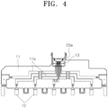
- FIG. 4 is a configurational diagram illustrating the other circuit of the pair of voltage measurement connection parts in the voltage measuring device for a battery cell of a vehicle according to one embodiment of the present invention
- FIG. 1 is a perspective view of a voltage measuring device for a battery cell of a vehicle according to on embodiment of the present invention
- FIG. 2 is an exploded perspective view of the voltage measuring device for a battery cell of a vehicle according to one embodiment of the present invention
- FIG. 3 is a configurational diagram illustrating one circuit of a pair of voltage measurement connection parts in the voltage measuring device for a
- FIG. 5 is a perspective view of a hinge coupler in the voltage measuring device for a battery cell of a vehicle according to one embodiment of the present invention
- FIG. 6 is a bottom perspective view of a flat cable and a cover member in the voltage measuring device for a battery cell of a vehicle according to one embodiment of the present invention.
- the voltage measuring device for a battery cell of a vehicle includes a pair of voltage measurement connection parts 10, an electrical connection part 20, and a voltage transmission connector 30.
- the pair of voltage measurement connection parts 10 are respectively connected to a negative electrode and a positive electrode of a battery cell so as to measure a voltage of the battery cell.
- the pair of voltage measurement connection parts 10 are connected to be electrically connected with each other by the electrical connection part 20 in a state of being spaced apart from each other.
- the pair of voltage measurement connection parts 10 transmit a measured voltage of the battery cell to the voltage transmission connector 30.
- each of the pair of voltage measurement connection parts 10 includes a body 11, a connection terminal 12, and a connection connector 13.
- the body 11 includes a circuit 11a and is formed of a synthetic resin material by injection molding.
- the body 11 serves to provide a space in which the connection terminal 12 and the connection connector 13 are installed.
- the circuit 11a is an electrical conducting pattern formed by laser direct structuring (LDS). Accordingly, since the body 11 itself constitutes the circuit 11a, a wire and a printed circuit board (PCB) substrate for allowing the connection terminal 12 and the connection connector 13 to be electrically connected with each other are not required. Consequently, not only the number of auxiliary parts can be reduced to reduce installation costs but also it is possible to eliminate the probability of an assembly defect due to incorrect assembling and missing parts.
- LDS laser direct structuring
- a circuit 11a formed in one body 11 of the pair of voltage measurement connection parts 10 is formed in a pattern for allowing each of the connection terminal 12 and the connection connector 13 to be electrically connected to the voltage transmission connector 30.
- a circuit 11a formed in the other body 11 of the pair of voltage measurement connection parts 10 is formed in a pattern for allowing the connection terminal 12 and the connection connector 13 to be electrically connected with each other.
- the pair of voltage measurement connection parts 10 may transmit a measured negative voltage and a measured positive voltage of the battery cell so as to allow the voltage transmission connector 30 to collect the measured negative voltage and the measured positive voltage.
- connection terminal 12 is provided in the body 11 so as to be electrically connected to the circuit 11a and connected to the battery cell.
- connection connector 13 is provided in the body 11 so as to be electrically connected to the circuit 11a and connected to the electrical connection part 20.
- connection connector 13 is connected to the electrical connection part 20 so as to transmit the measured negative voltage and the measured positive voltage of the battery cell, which are measured in the pair of voltage measurement connection parts 10, to the voltage transmission connector 30.
- the electrical connection part 20 is provided between the pair of voltage measurement connection parts 10 to connect the pair of voltage measurement connection parts 10 to be electrically connectable with each other.
- the electrical connection part 20 serves to guide the voltage of the battery cell measured in a voltage measurement connection part 10, which is not provided with the voltage transmission connector 30, of the pair of voltage measurement connection parts 10, to be transmitted to the voltage transmission connector 30.
- the electrical connection part 20 includes an electrical connection member 21, a cover member 22, and a hinge coupler 23.
- the electrical connection member 21 is formed in a flexible strip shape and allows the pair of voltage measurement connection parts 10 to electrically conduct.
- the electrical connection member 21 may be made of any one of a flat cable connected to the connection connector 13 and a flexible printed circuit board (FPCB) directly connected to the circuit 11a.
- FPCB flexible printed circuit board
- both ends of the electrical connection member 21 are connected to the connection connectors 13 provided in the pair of voltage measurement connection parts 10, and the electrical connection member 21 guides the voltage of the battery cell measured in the voltage measurement connection part 10 not provided with the voltage transmission connector 30 to be transmitted to the voltage transmission connector 30 through the circuit 11a of the voltage measurement connection part 10 provided with the voltage transmission connector 30.
- the cover member 22 supportably covers a flat cable so as to allow both ends of the flat cable to protrude.
- the cover member 22 not only serves to interconnect the pair of voltage measurement connection parts 10 through the hinge coupler 23, but also protects the flat cable from the outside by preventing the exposure of the flat cable.
- a support protrusion 22a for supporting the flat cable is formed to protrude from an inner side of the cover member 22 to prevent the flat cable from sagging.
- the hinge coupler 23 hinge-connects the cover member 22 to the body 11 of the voltage measurement connection part 10, thereby guiding the body 11 in a rotatable manner.
- the hinge coupler 23 includes a first coupler 23a and a second coupler 23b.
- the first coupler 23a is provided in each of the pair of voltage measurement connection parts 10, and the second coupler 23b is provided in the cover member 22 to be hinge-coupled to the first coupler 23a.
- a coupling hole 23c is formed in one of the first coupler 23a and the second coupler 23b, and a coupling protrusion 23d is formed in the other one of the second coupler 23b and the first coupler 23a.
- the voltage transmission connector 30 is provided at one of the pair of voltage measurement connection parts 10 to guide the voltage of the battery cell to be transmitted to the outside. That is, when a separate cable is connected, the voltage transmission connector 30 is configured to assist in transmitting the voltage of the battery cell measured in the voltage measurement connection part 10 to the outside.
- a voltage measuring device for a battery cell of a vehicle has a structure in which a negative voltage and a positive voltage of a battery cell, which are respectively measured by a pair of voltage measurement connection parts, are transmitted and collected at a voltage transmission connector through an electrical connection part. Consequently, not only the number of auxiliary parts can be reduced to reduce installation costs but also an assembly defect due to incorrect assembling and missing parts can be prevented such that there is an effect of improving assemblability.
Landscapes
- Engineering & Computer Science (AREA)
- Physics & Mathematics (AREA)
- General Physics & Mathematics (AREA)
- Manufacturing & Machinery (AREA)
- Chemical & Material Sciences (AREA)
- Chemical Kinetics & Catalysis (AREA)
- Electrochemistry (AREA)
- General Chemical & Material Sciences (AREA)
- Optics & Photonics (AREA)
- Mechanical Engineering (AREA)
- Plasma & Fusion (AREA)
- Microelectronics & Electronic Packaging (AREA)
- Life Sciences & Earth Sciences (AREA)
- Sustainable Development (AREA)
- Sustainable Energy (AREA)
- Power Engineering (AREA)
- Transportation (AREA)
- Secondary Cells (AREA)
- Measurement Of Current Or Voltage (AREA)
- Battery Mounting, Suspending (AREA)
- Electric Propulsion And Braking For Vehicles (AREA)
Claims (4)
- Spannungsmessvorrichtung für eine Batteriezelle eines Fahrzeugs, Folgendes umfassend:ein Paar von Spannungsmessungsanschlussteilen (10), die dazu ausgelegt sind, eine Spannung einer Batteriezelle durch Verbinden mit einer Minus-Elektrode bzw. einer Plus-Elektrode der Batteriezelle zu messen;ein elektrisches Anschlussteil (20), das zwischen dem Paar von Spannungsmessungsanschlussteilen (10) vorgesehen und dazu ausgelegt ist, das Paar von Spannungsmessungsanschlussteilen (10) so zu verbinden, dass sie elektrisch miteinander verbunden sind; undeinen Spannungsübertragungsverbinder (30), der an einem des Paars von Spannungsmessungsanschlussteilen (10) vorgesehen und dazu ausgelegt ist, die Spannung der Batteriezelle zur Übertragung nach außen zu leiten, wobeijedes des Paars von Spannungsmessungsanschlussteilen (10) Folgendes enthält:einen Körper (11) mit einer darin ausgebildeten Schaltung;eine Anschlussklemme (12), die in dem Körper (11) vorgesehen und mit der Batteriezelle verbunden ist; undeinen Anschlussverbinder (13), der in dem Körper (11) vorgesehen und mit dem elektrischen Anschlussteil (20) verbunden ist, dadurch gekennzeichnet, dassdie Schaltung ein elektrisch leitendes Muster enthält, das durch Laser-Direkt-Strukturierung (LOS) im Körper gebildet wird.
- Spannungsmessvorrichtung gemäß Anspruch 1, wobei:eine gedruckte Schaltung, die auf einem des Paars von Spannungsmessungsanschlussteilen (10) ausgebildet ist, in einem Muster ausgebildet ist, in dem jede der Anschlussklemmen (12) und der Anschlussverbinder (13) elektrisch mit dem Spannungsübertragungsverbinder (30) verbunden ist; undeine gedruckte Schaltung, die auf dem anderen des Paars von Spannungsmessungsanschlussteilen (10) ausgebildet ist, in einem Muster ausgebildet ist, in dem die Anschlussklemme (12) und der Anschlussverbinder (30) elektrisch miteinander verbunden sind.
- Spannungsmessvorrichtung gemäß einem oder mehreren der Ansprüche 1 bis 2, wobei das elektrische Anschlussteil (20) Folgendes enthält:ein elektrisches Anschlusselement (21), das so ausgelegt ist, dass das Paar von Spannungsmessungsanschlussteilen (10) elektrisch miteinander verbunden werden kann;ein Abdeckelement (22), das dazu ausgelegt ist, das elektrische Anschlusselement (21) stützend abzudecken; undeine Gelenkkupplung (23), die dazu ausgelegt ist, das Abdeckelement (22) mit dem Paar von Spannungsmessungsanschlussteilen (10) gelenkig zu verbinden, um das Spannungsmessungsanschlussteil (10) drehbar zu führen.
- Spannungsmessvorrichtung gemäß Anspruch 3, wobei die Gelenkkupplung (23) Folgendes aufweist:eine erste Kupplung (23a), die in jedem des Paars von Spannungsmessungsanschlussteilen (10) vorgesehen ist; undeine zweite Kupplung (23b), die an dem Abdeckelement (22) vorgesehen ist, um mit der ersten Kupplung gelenkig verbunden zu werden.
Applications Claiming Priority (1)
| Application Number | Priority Date | Filing Date | Title |
|---|---|---|---|
| KR1020180047593A KR101944111B1 (ko) | 2018-04-24 | 2018-04-24 | 차량용 배터리 셀의 전압 측정장치 |
Publications (2)
| Publication Number | Publication Date |
|---|---|
| EP3573170A1 EP3573170A1 (de) | 2019-11-27 |
| EP3573170B1 true EP3573170B1 (de) | 2023-04-05 |
Family
ID=65276727
Family Applications (1)
| Application Number | Title | Priority Date | Filing Date |
|---|---|---|---|
| EP19168991.8A Active EP3573170B1 (de) | 2018-04-24 | 2019-04-12 | Spannungsmessvorrichtung für die batteriezelle eines fahrzeugs |
Country Status (4)
| Country | Link |
|---|---|
| US (1) | US10955480B2 (de) |
| EP (1) | EP3573170B1 (de) |
| KR (1) | KR101944111B1 (de) |
| CN (1) | CN110400979B (de) |
Families Citing this family (3)
| Publication number | Priority date | Publication date | Assignee | Title |
|---|---|---|---|---|
| KR102503536B1 (ko) | 2019-06-18 | 2023-02-23 | 주식회사 엘지에너지솔루션 | 전지 모듈 및 이를 포함하는 전지팩 |
| KR102930099B1 (ko) | 2021-01-12 | 2026-02-25 | 에스케이온 주식회사 | 배터리 모듈 |
| KR20220114913A (ko) * | 2021-02-09 | 2022-08-17 | 주식회사 엘지에너지솔루션 | 커넥터의 효율적인 레이아웃을 위한 버스바 프레임을 구비한 배터리 모듈 및 이를 포함하는 배터리 팩. |
Family Cites Families (13)
| Publication number | Priority date | Publication date | Assignee | Title |
|---|---|---|---|---|
| CN102379058B (zh) * | 2009-04-01 | 2014-06-18 | 株式会社Lg化学 | 电压感测部件和采用该电压感测部件的电池模块 |
| KR101186628B1 (ko) | 2011-05-04 | 2012-09-27 | 주식회사 경신 | 차량용 배터리모듈의 전압센싱모듈 |
| KR101469518B1 (ko) * | 2011-08-01 | 2014-12-05 | 주식회사 엘지화학 | 안전성이 향상된 전지모듈 |
| US9746525B2 (en) * | 2011-09-08 | 2017-08-29 | Hitachi Automotive Systems, Ltd. | Battery system monitoring device |
| US8986872B2 (en) * | 2012-02-15 | 2015-03-24 | GM Global Technology Operations LLC | Battery design |
| KR101410000B1 (ko) * | 2012-05-16 | 2014-07-02 | 엘지전자 주식회사 | 에너지 저장장치 및 그 동작방법 |
| JP5910487B2 (ja) * | 2012-12-25 | 2016-04-27 | 株式会社オートネットワーク技術研究所 | 配線用モジュール |
| US9140759B2 (en) * | 2013-11-12 | 2015-09-22 | Ford Global Technologies, Llc | Electric vehicle battery pack voltage monitoring |
| DE102014218131A1 (de) * | 2014-09-10 | 2016-03-10 | Bayerische Motoren Werke Aktiengesellschaft | Messsystem zur Batteriezustandsbestimmung |
| KR102551738B1 (ko) * | 2014-10-24 | 2023-07-06 | 타이코에이엠피 주식회사 | 센싱 모듈 조립체 및 이를 포함하는 배터리 모듈 조립체 |
| US10122007B2 (en) * | 2015-06-25 | 2018-11-06 | Te Connectivity Corporation | Cover assembly for a battery module |
| JP6459876B2 (ja) * | 2015-09-25 | 2019-01-30 | 株式会社オートネットワーク技術研究所 | コネクタ装着構造 |
| KR101829350B1 (ko) * | 2016-12-30 | 2018-02-14 | 한국단자공업 주식회사 | 배터리모듈용 센싱장치 |
-
2018
- 2018-04-24 KR KR1020180047593A patent/KR101944111B1/ko not_active Expired - Fee Related
-
2019
- 2019-04-12 EP EP19168991.8A patent/EP3573170B1/de active Active
- 2019-04-17 US US16/386,416 patent/US10955480B2/en not_active Expired - Fee Related
- 2019-04-22 CN CN201910322972.5A patent/CN110400979B/zh not_active Expired - Fee Related
Also Published As
| Publication number | Publication date |
|---|---|
| CN110400979B (zh) | 2022-09-23 |
| EP3573170A1 (de) | 2019-11-27 |
| US20190324087A1 (en) | 2019-10-24 |
| KR101944111B1 (ko) | 2019-01-30 |
| CN110400979A (zh) | 2019-11-01 |
| US10955480B2 (en) | 2021-03-23 |
Similar Documents
| Publication | Publication Date | Title |
|---|---|---|
| JP6688762B2 (ja) | 電池用温度センサ及びその取付構造 | |
| EP3605741B1 (de) | An einem verbinder befestigter schaltungskörper und sammelschienenmodul | |
| US20190088912A1 (en) | Battery connection module | |
| KR101537457B1 (ko) | 배터리 모듈 | |
| US20190088918A1 (en) | Battery connection module | |
| US9343725B2 (en) | Bus bar module and power supply unit | |
| EP3573170B1 (de) | Spannungsmessvorrichtung für die batteriezelle eines fahrzeugs | |
| US7663376B2 (en) | Printed circuit board for sensing voltage drop | |
| CN109524608A (zh) | 电池连接模块 | |
| US20190245185A1 (en) | Battery wiring module | |
| KR101723037B1 (ko) | 이차전지팩의 이차전지 연결장치 | |
| KR102381583B1 (ko) | 모니터링 장치를 구비하는 전기자동차용 배터리 모듈 | |
| US20190386282A1 (en) | Connection module | |
| US8945734B2 (en) | Secondary battery including protection circuit module | |
| US20240234966A9 (en) | Wiring module | |
| US20250192383A1 (en) | Battery module | |
| US20250149748A1 (en) | Connection module set, electrode connection member set, and battery pack | |
| KR20180074457A (ko) | 배터리 모듈 | |
| JP7082521B2 (ja) | 蓄電装置 | |
| JP2018045960A (ja) | コネクタ装置 | |
| US20130244060A1 (en) | Battery pack | |
| US20240283116A1 (en) | Protector and power storage module | |
| CN115425373B (zh) | 一种电池模组以及电动汽车 | |
| KR101609646B1 (ko) | 이차전지팩의 이차전지 연결장치 | |
| JP7839470B2 (ja) | 配線モジュール |
Legal Events
| Date | Code | Title | Description |
|---|---|---|---|
| PUAI | Public reference made under article 153(3) epc to a published international application that has entered the european phase |
Free format text: ORIGINAL CODE: 0009012 |
|
| STAA | Information on the status of an ep patent application or granted ep patent |
Free format text: STATUS: THE APPLICATION HAS BEEN PUBLISHED |
|
| AK | Designated contracting states |
Kind code of ref document: A1 Designated state(s): AL AT BE BG CH CY CZ DE DK EE ES FI FR GB GR HR HU IE IS IT LI LT LU LV MC MK MT NL NO PL PT RO RS SE SI SK SM TR |
|
| AX | Request for extension of the european patent |
Extension state: BA ME |
|
| STAA | Information on the status of an ep patent application or granted ep patent |
Free format text: STATUS: REQUEST FOR EXAMINATION WAS MADE |
|
| 17P | Request for examination filed |
Effective date: 20200526 |
|
| RBV | Designated contracting states (corrected) |
Designated state(s): AL AT BE BG CH CY CZ DE DK EE ES FI FR GB GR HR HU IE IS IT LI LT LU LV MC MK MT NL NO PL PT RO RS SE SI SK SM TR |
|
| GRAP | Despatch of communication of intention to grant a patent |
Free format text: ORIGINAL CODE: EPIDOSNIGR1 |
|
| STAA | Information on the status of an ep patent application or granted ep patent |
Free format text: STATUS: GRANT OF PATENT IS INTENDED |
|
| INTG | Intention to grant announced |
Effective date: 20221024 |
|
| GRAS | Grant fee paid |
Free format text: ORIGINAL CODE: EPIDOSNIGR3 |
|
| GRAA | (expected) grant |
Free format text: ORIGINAL CODE: 0009210 |
|
| STAA | Information on the status of an ep patent application or granted ep patent |
Free format text: STATUS: THE PATENT HAS BEEN GRANTED |
|
| AK | Designated contracting states |
Kind code of ref document: B1 Designated state(s): AL AT BE BG CH CY CZ DE DK EE ES FI FR GB GR HR HU IE IS IT LI LT LU LV MC MK MT NL NO PL PT RO RS SE SI SK SM TR |
|
| REG | Reference to a national code |
Ref country code: GB Ref legal event code: FG4D |
|
| REG | Reference to a national code |
Ref country code: DE Ref legal event code: R096 Ref document number: 602019027089 Country of ref document: DE |
|
| REG | Reference to a national code |
Ref country code: CH Ref legal event code: EP |
|
| REG | Reference to a national code |
Ref country code: AT Ref legal event code: REF Ref document number: 1558940 Country of ref document: AT Kind code of ref document: T Effective date: 20230415 |
|
| REG | Reference to a national code |
Ref country code: IE Ref legal event code: FG4D |
|
| REG | Reference to a national code |
Ref country code: LT Ref legal event code: MG9D |
|
| REG | Reference to a national code |
Ref country code: NL Ref legal event code: MP Effective date: 20230405 |
|
| REG | Reference to a national code |
Ref country code: AT Ref legal event code: MK05 Ref document number: 1558940 Country of ref document: AT Kind code of ref document: T Effective date: 20230405 |
|
| PG25 | Lapsed in a contracting state [announced via postgrant information from national office to epo] |
Ref country code: NL Free format text: LAPSE BECAUSE OF FAILURE TO SUBMIT A TRANSLATION OF THE DESCRIPTION OR TO PAY THE FEE WITHIN THE PRESCRIBED TIME-LIMIT Effective date: 20230405 |
|
| PG25 | Lapsed in a contracting state [announced via postgrant information from national office to epo] |
Ref country code: SE Free format text: LAPSE BECAUSE OF FAILURE TO SUBMIT A TRANSLATION OF THE DESCRIPTION OR TO PAY THE FEE WITHIN THE PRESCRIBED TIME-LIMIT Effective date: 20230405 Ref country code: PT Free format text: LAPSE BECAUSE OF FAILURE TO SUBMIT A TRANSLATION OF THE DESCRIPTION OR TO PAY THE FEE WITHIN THE PRESCRIBED TIME-LIMIT Effective date: 20230807 Ref country code: NO Free format text: LAPSE BECAUSE OF FAILURE TO SUBMIT A TRANSLATION OF THE DESCRIPTION OR TO PAY THE FEE WITHIN THE PRESCRIBED TIME-LIMIT Effective date: 20230705 Ref country code: ES Free format text: LAPSE BECAUSE OF FAILURE TO SUBMIT A TRANSLATION OF THE DESCRIPTION OR TO PAY THE FEE WITHIN THE PRESCRIBED TIME-LIMIT Effective date: 20230405 Ref country code: AT Free format text: LAPSE BECAUSE OF FAILURE TO SUBMIT A TRANSLATION OF THE DESCRIPTION OR TO PAY THE FEE WITHIN THE PRESCRIBED TIME-LIMIT Effective date: 20230405 |
|
| REG | Reference to a national code |
Ref country code: DE Ref legal event code: R119 Ref document number: 602019027089 Country of ref document: DE |
|
| PG25 | Lapsed in a contracting state [announced via postgrant information from national office to epo] |
Ref country code: RS Free format text: LAPSE BECAUSE OF FAILURE TO SUBMIT A TRANSLATION OF THE DESCRIPTION OR TO PAY THE FEE WITHIN THE PRESCRIBED TIME-LIMIT Effective date: 20230405 Ref country code: PL Free format text: LAPSE BECAUSE OF FAILURE TO SUBMIT A TRANSLATION OF THE DESCRIPTION OR TO PAY THE FEE WITHIN THE PRESCRIBED TIME-LIMIT Effective date: 20230405 Ref country code: LV Free format text: LAPSE BECAUSE OF FAILURE TO SUBMIT A TRANSLATION OF THE DESCRIPTION OR TO PAY THE FEE WITHIN THE PRESCRIBED TIME-LIMIT Effective date: 20230405 Ref country code: LT Free format text: LAPSE BECAUSE OF FAILURE TO SUBMIT A TRANSLATION OF THE DESCRIPTION OR TO PAY THE FEE WITHIN THE PRESCRIBED TIME-LIMIT Effective date: 20230405 Ref country code: IS Free format text: LAPSE BECAUSE OF FAILURE TO SUBMIT A TRANSLATION OF THE DESCRIPTION OR TO PAY THE FEE WITHIN THE PRESCRIBED TIME-LIMIT Effective date: 20230805 Ref country code: HR Free format text: LAPSE BECAUSE OF FAILURE TO SUBMIT A TRANSLATION OF THE DESCRIPTION OR TO PAY THE FEE WITHIN THE PRESCRIBED TIME-LIMIT Effective date: 20230405 Ref country code: GR Free format text: LAPSE BECAUSE OF FAILURE TO SUBMIT A TRANSLATION OF THE DESCRIPTION OR TO PAY THE FEE WITHIN THE PRESCRIBED TIME-LIMIT Effective date: 20230706 Ref country code: AL Free format text: LAPSE BECAUSE OF FAILURE TO SUBMIT A TRANSLATION OF THE DESCRIPTION OR TO PAY THE FEE WITHIN THE PRESCRIBED TIME-LIMIT Effective date: 20230405 |
|
| REG | Reference to a national code |
Ref country code: CH Ref legal event code: PL |
|
| PG25 | Lapsed in a contracting state [announced via postgrant information from national office to epo] |
Ref country code: LU Free format text: LAPSE BECAUSE OF NON-PAYMENT OF DUE FEES Effective date: 20230412 Ref country code: FI Free format text: LAPSE BECAUSE OF FAILURE TO SUBMIT A TRANSLATION OF THE DESCRIPTION OR TO PAY THE FEE WITHIN THE PRESCRIBED TIME-LIMIT Effective date: 20230405 |
|
| REG | Reference to a national code |
Ref country code: BE Ref legal event code: MM Effective date: 20230430 |
|
| PG25 | Lapsed in a contracting state [announced via postgrant information from national office to epo] |
Ref country code: SK Free format text: LAPSE BECAUSE OF FAILURE TO SUBMIT A TRANSLATION OF THE DESCRIPTION OR TO PAY THE FEE WITHIN THE PRESCRIBED TIME-LIMIT Effective date: 20230405 |
|
| PG25 | Lapsed in a contracting state [announced via postgrant information from national office to epo] |
Ref country code: MC Free format text: LAPSE BECAUSE OF FAILURE TO SUBMIT A TRANSLATION OF THE DESCRIPTION OR TO PAY THE FEE WITHIN THE PRESCRIBED TIME-LIMIT Effective date: 20230405 |
|
| PG25 | Lapsed in a contracting state [announced via postgrant information from national office to epo] |
Ref country code: SM Free format text: LAPSE BECAUSE OF FAILURE TO SUBMIT A TRANSLATION OF THE DESCRIPTION OR TO PAY THE FEE WITHIN THE PRESCRIBED TIME-LIMIT Effective date: 20230405 Ref country code: SK Free format text: LAPSE BECAUSE OF FAILURE TO SUBMIT A TRANSLATION OF THE DESCRIPTION OR TO PAY THE FEE WITHIN THE PRESCRIBED TIME-LIMIT Effective date: 20230405 Ref country code: RO Free format text: LAPSE BECAUSE OF FAILURE TO SUBMIT A TRANSLATION OF THE DESCRIPTION OR TO PAY THE FEE WITHIN THE PRESCRIBED TIME-LIMIT Effective date: 20230405 Ref country code: MC Free format text: LAPSE BECAUSE OF FAILURE TO SUBMIT A TRANSLATION OF THE DESCRIPTION OR TO PAY THE FEE WITHIN THE PRESCRIBED TIME-LIMIT Effective date: 20230405 Ref country code: LI Free format text: LAPSE BECAUSE OF NON-PAYMENT OF DUE FEES Effective date: 20230430 Ref country code: EE Free format text: LAPSE BECAUSE OF FAILURE TO SUBMIT A TRANSLATION OF THE DESCRIPTION OR TO PAY THE FEE WITHIN THE PRESCRIBED TIME-LIMIT Effective date: 20230405 Ref country code: DK Free format text: LAPSE BECAUSE OF FAILURE TO SUBMIT A TRANSLATION OF THE DESCRIPTION OR TO PAY THE FEE WITHIN THE PRESCRIBED TIME-LIMIT Effective date: 20230405 Ref country code: DE Free format text: LAPSE BECAUSE OF NON-PAYMENT OF DUE FEES Effective date: 20231103 Ref country code: CZ Free format text: LAPSE BECAUSE OF FAILURE TO SUBMIT A TRANSLATION OF THE DESCRIPTION OR TO PAY THE FEE WITHIN THE PRESCRIBED TIME-LIMIT Effective date: 20230405 Ref country code: CH Free format text: LAPSE BECAUSE OF NON-PAYMENT OF DUE FEES Effective date: 20230430 |
|
| PLBE | No opposition filed within time limit |
Free format text: ORIGINAL CODE: 0009261 |
|
| STAA | Information on the status of an ep patent application or granted ep patent |
Free format text: STATUS: NO OPPOSITION FILED WITHIN TIME LIMIT |
|
| REG | Reference to a national code |
Ref country code: IE Ref legal event code: MM4A |
|
| PG25 | Lapsed in a contracting state [announced via postgrant information from national office to epo] |
Ref country code: BE Free format text: LAPSE BECAUSE OF NON-PAYMENT OF DUE FEES Effective date: 20230430 |
|
| 26N | No opposition filed |
Effective date: 20240108 |
|
| GBPC | Gb: european patent ceased through non-payment of renewal fee |
Effective date: 20230705 |
|
| PG25 | Lapsed in a contracting state [announced via postgrant information from national office to epo] |
Ref country code: IE Free format text: LAPSE BECAUSE OF NON-PAYMENT OF DUE FEES Effective date: 20230412 |
|
| PG25 | Lapsed in a contracting state [announced via postgrant information from national office to epo] |
Ref country code: IE Free format text: LAPSE BECAUSE OF NON-PAYMENT OF DUE FEES Effective date: 20230412 Ref country code: GB Free format text: LAPSE BECAUSE OF NON-PAYMENT OF DUE FEES Effective date: 20230705 |
|
| PG25 | Lapsed in a contracting state [announced via postgrant information from national office to epo] |
Ref country code: SI Free format text: LAPSE BECAUSE OF FAILURE TO SUBMIT A TRANSLATION OF THE DESCRIPTION OR TO PAY THE FEE WITHIN THE PRESCRIBED TIME-LIMIT Effective date: 20230405 |
|
| PG25 | Lapsed in a contracting state [announced via postgrant information from national office to epo] |
Ref country code: SI Free format text: LAPSE BECAUSE OF FAILURE TO SUBMIT A TRANSLATION OF THE DESCRIPTION OR TO PAY THE FEE WITHIN THE PRESCRIBED TIME-LIMIT Effective date: 20230405 Ref country code: IT Free format text: LAPSE BECAUSE OF FAILURE TO SUBMIT A TRANSLATION OF THE DESCRIPTION OR TO PAY THE FEE WITHIN THE PRESCRIBED TIME-LIMIT Effective date: 20230405 Ref country code: FR Free format text: LAPSE BECAUSE OF NON-PAYMENT OF DUE FEES Effective date: 20230605 |
|
| PG25 | Lapsed in a contracting state [announced via postgrant information from national office to epo] |
Ref country code: BG Free format text: LAPSE BECAUSE OF FAILURE TO SUBMIT A TRANSLATION OF THE DESCRIPTION OR TO PAY THE FEE WITHIN THE PRESCRIBED TIME-LIMIT Effective date: 20230405 |
|
| PG25 | Lapsed in a contracting state [announced via postgrant information from national office to epo] |
Ref country code: BG Free format text: LAPSE BECAUSE OF FAILURE TO SUBMIT A TRANSLATION OF THE DESCRIPTION OR TO PAY THE FEE WITHIN THE PRESCRIBED TIME-LIMIT Effective date: 20230405 |
|
| PG25 | Lapsed in a contracting state [announced via postgrant information from national office to epo] |
Ref country code: CY Free format text: LAPSE BECAUSE OF FAILURE TO SUBMIT A TRANSLATION OF THE DESCRIPTION OR TO PAY THE FEE WITHIN THE PRESCRIBED TIME-LIMIT; INVALID AB INITIO Effective date: 20190412 |
|
| PG25 | Lapsed in a contracting state [announced via postgrant information from national office to epo] |
Ref country code: HU Free format text: LAPSE BECAUSE OF FAILURE TO SUBMIT A TRANSLATION OF THE DESCRIPTION OR TO PAY THE FEE WITHIN THE PRESCRIBED TIME-LIMIT; INVALID AB INITIO Effective date: 20190412 |
|
| PG25 | Lapsed in a contracting state [announced via postgrant information from national office to epo] |
Ref country code: TR Free format text: LAPSE BECAUSE OF FAILURE TO SUBMIT A TRANSLATION OF THE DESCRIPTION OR TO PAY THE FEE WITHIN THE PRESCRIBED TIME-LIMIT Effective date: 20230405 |