EP3573139A1 - Recyclable pouch-type secondary battery, battery module comprising same, and battery module recycling method - Google Patents
Recyclable pouch-type secondary battery, battery module comprising same, and battery module recycling method Download PDFInfo
- Publication number
- EP3573139A1 EP3573139A1 EP18791492.4A EP18791492A EP3573139A1 EP 3573139 A1 EP3573139 A1 EP 3573139A1 EP 18791492 A EP18791492 A EP 18791492A EP 3573139 A1 EP3573139 A1 EP 3573139A1
- Authority
- EP
- European Patent Office
- Prior art keywords
- type secondary
- battery module
- pouch type
- electrode leads
- electrode
- Prior art date
- Legal status (The legal status is an assumption and is not a legal conclusion. Google has not performed a legal analysis and makes no representation as to the accuracy of the status listed.)
- Granted
Links
Images





Classifications
-
- H—ELECTRICITY
- H01—ELECTRIC ELEMENTS
- H01M—PROCESSES OR MEANS, e.g. BATTERIES, FOR THE DIRECT CONVERSION OF CHEMICAL ENERGY INTO ELECTRICAL ENERGY
- H01M10/00—Secondary cells; Manufacture thereof
- H01M10/04—Construction or manufacture in general
- H01M10/045—Cells or batteries with folded plate-like electrodes
-
- H—ELECTRICITY
- H01—ELECTRIC ELEMENTS
- H01M—PROCESSES OR MEANS, e.g. BATTERIES, FOR THE DIRECT CONVERSION OF CHEMICAL ENERGY INTO ELECTRICAL ENERGY
- H01M10/00—Secondary cells; Manufacture thereof
- H01M10/04—Construction or manufacture in general
-
- H—ELECTRICITY
- H01—ELECTRIC ELEMENTS
- H01M—PROCESSES OR MEANS, e.g. BATTERIES, FOR THE DIRECT CONVERSION OF CHEMICAL ENERGY INTO ELECTRICAL ENERGY
- H01M10/00—Secondary cells; Manufacture thereof
- H01M10/04—Construction or manufacture in general
- H01M10/0413—Large-sized flat cells or batteries for motive or stationary systems with plate-like electrodes
-
- H—ELECTRICITY
- H01—ELECTRIC ELEMENTS
- H01M—PROCESSES OR MEANS, e.g. BATTERIES, FOR THE DIRECT CONVERSION OF CHEMICAL ENERGY INTO ELECTRICAL ENERGY
- H01M10/00—Secondary cells; Manufacture thereof
- H01M10/54—Reclaiming serviceable parts of waste accumulators
-
- H—ELECTRICITY
- H01—ELECTRIC ELEMENTS
- H01M—PROCESSES OR MEANS, e.g. BATTERIES, FOR THE DIRECT CONVERSION OF CHEMICAL ENERGY INTO ELECTRICAL ENERGY
- H01M50/00—Constructional details or processes of manufacture of the non-active parts of electrochemical cells other than fuel cells, e.g. hybrid cells
- H01M50/10—Primary casings; Jackets or wrappings
- H01M50/102—Primary casings; Jackets or wrappings characterised by their shape or physical structure
- H01M50/105—Pouches or flexible bags
-
- H—ELECTRICITY
- H01—ELECTRIC ELEMENTS
- H01M—PROCESSES OR MEANS, e.g. BATTERIES, FOR THE DIRECT CONVERSION OF CHEMICAL ENERGY INTO ELECTRICAL ENERGY
- H01M50/00—Constructional details or processes of manufacture of the non-active parts of electrochemical cells other than fuel cells, e.g. hybrid cells
- H01M50/10—Primary casings; Jackets or wrappings
- H01M50/116—Primary casings; Jackets or wrappings characterised by the material
- H01M50/117—Inorganic material
- H01M50/119—Metals
-
- H—ELECTRICITY
- H01—ELECTRIC ELEMENTS
- H01M—PROCESSES OR MEANS, e.g. BATTERIES, FOR THE DIRECT CONVERSION OF CHEMICAL ENERGY INTO ELECTRICAL ENERGY
- H01M50/00—Constructional details or processes of manufacture of the non-active parts of electrochemical cells other than fuel cells, e.g. hybrid cells
- H01M50/10—Primary casings; Jackets or wrappings
- H01M50/116—Primary casings; Jackets or wrappings characterised by the material
- H01M50/124—Primary casings; Jackets or wrappings characterised by the material having a layered structure
-
- H—ELECTRICITY
- H01—ELECTRIC ELEMENTS
- H01M—PROCESSES OR MEANS, e.g. BATTERIES, FOR THE DIRECT CONVERSION OF CHEMICAL ENERGY INTO ELECTRICAL ENERGY
- H01M50/00—Constructional details or processes of manufacture of the non-active parts of electrochemical cells other than fuel cells, e.g. hybrid cells
- H01M50/10—Primary casings; Jackets or wrappings
- H01M50/172—Arrangements of electric connectors penetrating the casing
- H01M50/174—Arrangements of electric connectors penetrating the casing adapted for the shape of the cells
- H01M50/178—Arrangements of electric connectors penetrating the casing adapted for the shape of the cells for pouch or flexible bag cells
-
- H—ELECTRICITY
- H01—ELECTRIC ELEMENTS
- H01M—PROCESSES OR MEANS, e.g. BATTERIES, FOR THE DIRECT CONVERSION OF CHEMICAL ENERGY INTO ELECTRICAL ENERGY
- H01M50/00—Constructional details or processes of manufacture of the non-active parts of electrochemical cells other than fuel cells, e.g. hybrid cells
- H01M50/20—Mountings; Secondary casings or frames; Racks, modules or packs; Suspension devices; Shock absorbers; Transport or carrying devices; Holders
- H01M50/204—Racks, modules or packs for multiple batteries or multiple cells
- H01M50/207—Racks, modules or packs for multiple batteries or multiple cells characterised by their shape
- H01M50/211—Racks, modules or packs for multiple batteries or multiple cells characterised by their shape adapted for pouch cells
-
- H—ELECTRICITY
- H01—ELECTRIC ELEMENTS
- H01M—PROCESSES OR MEANS, e.g. BATTERIES, FOR THE DIRECT CONVERSION OF CHEMICAL ENERGY INTO ELECTRICAL ENERGY
- H01M50/00—Constructional details or processes of manufacture of the non-active parts of electrochemical cells other than fuel cells, e.g. hybrid cells
- H01M50/50—Current conducting connections for cells or batteries
-
- H—ELECTRICITY
- H01—ELECTRIC ELEMENTS
- H01M—PROCESSES OR MEANS, e.g. BATTERIES, FOR THE DIRECT CONVERSION OF CHEMICAL ENERGY INTO ELECTRICAL ENERGY
- H01M50/00—Constructional details or processes of manufacture of the non-active parts of electrochemical cells other than fuel cells, e.g. hybrid cells
- H01M50/50—Current conducting connections for cells or batteries
- H01M50/502—Interconnectors for connecting terminals of adjacent batteries; Interconnectors for connecting cells outside a battery casing
- H01M50/514—Methods for interconnecting adjacent batteries or cells
- H01M50/516—Methods for interconnecting adjacent batteries or cells by welding, soldering or brazing
-
- H—ELECTRICITY
- H01—ELECTRIC ELEMENTS
- H01M—PROCESSES OR MEANS, e.g. BATTERIES, FOR THE DIRECT CONVERSION OF CHEMICAL ENERGY INTO ELECTRICAL ENERGY
- H01M50/00—Constructional details or processes of manufacture of the non-active parts of electrochemical cells other than fuel cells, e.g. hybrid cells
- H01M50/50—Current conducting connections for cells or batteries
- H01M50/531—Electrode connections inside a battery casing
- H01M50/533—Electrode connections inside a battery casing characterised by the shape of the leads or tabs
-
- H—ELECTRICITY
- H01—ELECTRIC ELEMENTS
- H01M—PROCESSES OR MEANS, e.g. BATTERIES, FOR THE DIRECT CONVERSION OF CHEMICAL ENERGY INTO ELECTRICAL ENERGY
- H01M50/00—Constructional details or processes of manufacture of the non-active parts of electrochemical cells other than fuel cells, e.g. hybrid cells
- H01M50/50—Current conducting connections for cells or batteries
- H01M50/543—Terminals
- H01M50/547—Terminals characterised by the disposition of the terminals on the cells
- H01M50/548—Terminals characterised by the disposition of the terminals on the cells on opposite sides of the cell
-
- H—ELECTRICITY
- H01—ELECTRIC ELEMENTS
- H01M—PROCESSES OR MEANS, e.g. BATTERIES, FOR THE DIRECT CONVERSION OF CHEMICAL ENERGY INTO ELECTRICAL ENERGY
- H01M50/00—Constructional details or processes of manufacture of the non-active parts of electrochemical cells other than fuel cells, e.g. hybrid cells
- H01M50/50—Current conducting connections for cells or batteries
- H01M50/543—Terminals
- H01M50/552—Terminals characterised by their shape
- H01M50/553—Terminals adapted for prismatic, pouch or rectangular cells
-
- H—ELECTRICITY
- H01—ELECTRIC ELEMENTS
- H01M—PROCESSES OR MEANS, e.g. BATTERIES, FOR THE DIRECT CONVERSION OF CHEMICAL ENERGY INTO ELECTRICAL ENERGY
- H01M2220/00—Batteries for particular applications
- H01M2220/10—Batteries in stationary systems, e.g. emergency power source in plant
-
- H—ELECTRICITY
- H01—ELECTRIC ELEMENTS
- H01M—PROCESSES OR MEANS, e.g. BATTERIES, FOR THE DIRECT CONVERSION OF CHEMICAL ENERGY INTO ELECTRICAL ENERGY
- H01M2220/00—Batteries for particular applications
- H01M2220/20—Batteries in motive systems, e.g. vehicle, ship, plane
-
- Y—GENERAL TAGGING OF NEW TECHNOLOGICAL DEVELOPMENTS; GENERAL TAGGING OF CROSS-SECTIONAL TECHNOLOGIES SPANNING OVER SEVERAL SECTIONS OF THE IPC; TECHNICAL SUBJECTS COVERED BY FORMER USPC CROSS-REFERENCE ART COLLECTIONS [XRACs] AND DIGESTS
- Y02—TECHNOLOGIES OR APPLICATIONS FOR MITIGATION OR ADAPTATION AGAINST CLIMATE CHANGE
- Y02E—REDUCTION OF GREENHOUSE GAS [GHG] EMISSIONS, RELATED TO ENERGY GENERATION, TRANSMISSION OR DISTRIBUTION
- Y02E60/00—Enabling technologies; Technologies with a potential or indirect contribution to GHG emissions mitigation
- Y02E60/10—Energy storage using batteries
-
- Y—GENERAL TAGGING OF NEW TECHNOLOGICAL DEVELOPMENTS; GENERAL TAGGING OF CROSS-SECTIONAL TECHNOLOGIES SPANNING OVER SEVERAL SECTIONS OF THE IPC; TECHNICAL SUBJECTS COVERED BY FORMER USPC CROSS-REFERENCE ART COLLECTIONS [XRACs] AND DIGESTS
- Y02—TECHNOLOGIES OR APPLICATIONS FOR MITIGATION OR ADAPTATION AGAINST CLIMATE CHANGE
- Y02W—CLIMATE CHANGE MITIGATION TECHNOLOGIES RELATED TO WASTEWATER TREATMENT OR WASTE MANAGEMENT
- Y02W30/00—Technologies for solid waste management
- Y02W30/50—Reuse, recycling or recovery technologies
- Y02W30/84—Recycling of batteries or fuel cells
Definitions
- the present disclosure relates to a pouch type secondary battery, and more particularly, to a reusable pouch type secondary battery and a battery module comprising the same.
- the present disclosure also relates to a method of reusing the battery module and a method of reusing a general battery module.
- the present application claims priority to Korean Patent Application No. 10-2017-0052906 filed in the Republic of Korea on April 25, 2017, the disclosures of which are incorporated herein by reference.
- lithium secondary batteries have little or no memory effect, and thus they are gaining more attention than nickel-based secondary batteries for their advantages of free charging/discharging, low self-discharging, and high energy density.
- a battery pack is manufactured using battery modules in which many secondary batteries are connected in series and/or in parallel.
- pouch type secondary batteries are widely used in medium- and large-scale devices because they are easy to stack.
- FIG. 1 shows a general pouch type secondary battery.
- the general pouch type secondary battery 1 has a sealing part 30 formed by sealing a pouch case 10 in which an electrode assembly 20 is received, and electrode leads 40, 45 are welded to a positive electrode tab and a negative electrode tab of the electrode assembly 20 respectively and exposed through the pouch case 10.
- a lead film 50 is interposed between the pouch case 10 and the electrode leads 40, 45.
- a portion where the electrode leads 40, 45 are drawn is called terrace T.
- a plurality of pouch type secondary batteries 1 is stacked, and two adjacent pouch type secondary batteries 1 are connected in series and/or in parallel such that the electrode leads 40, 45 provided in each pouch type secondary battery 1 are connected to each other to construct a battery module 11 with improved capacity and output.
- the reference numeral 60 is a structure that structurally supports the battery module 11, such as a molded product.
- the battery module 11 When connecting the pouch type secondary batteries 1 to manufacture the battery module 11, laser welding L is applied to connect the electrode leads 40, 45.
- the battery module 11 is used for an automobile battery, and after the intended service life expires, it would be desirable that the battery module 11 is used for a second purpose, for example, an ESS having less strict capacity retention rate or other conditions. To this end, it is necessary to dissemble the existing connection structure of the first battery module and connect the pouch type secondary batteries by a different method to manufacture a new battery module for the purpose of reuse. However, conventionally, it was not easy to reuse because it was impossible to separate the electrode leads 40, 45 joined by laser welding L using a non-destructive method.
- the present disclosure is designed to solve the above-described problem, and therefore the present disclosure is directed to providing a reusable pouch type secondary battery.
- the present disclosure is further directed to providing a reusable battery module.
- the present disclosure is further directed to providing a method of reusing a battery module.
- a pouch type secondary battery is a pouch type secondary battery in which an electrode lead of the pouch type secondary battery and an electrode lead of an adjacent different pouch type secondary battery are welded to construct a battery module, and the electrode lead includes a length extended part so that the electrode leads of remaining length after cutting a welded part of the electrode leads are welded again.
- the pouch type secondary battery has a lead film between a pouch case and the electrode lead, and the lead film may include a surplus part so that the lead film is formed to the length extended part.
- the lead film may include a notch on two sides of a part sticking out of the pouch case to remove the surplus part.
- the pouch type secondary battery further includes an insulation tape that covers the length extended part.
- the insulation tape may be a composite film in which a PI or PP film has an adhesive layer.
- a battery module according to the present disclosure includes the pouch type secondary battery.
- the battery module according to the present disclosure includes a plurality of stacked pouch type secondary batteries, each having an electrode lead including a length extended part, so that electrode leads of remaining length after cutting a welded part of the electrode leads are welded again, with the electrode leads of adjacent pouch type secondary batteries being welded.
- the electrode lead of the pouch type secondary battery included in the battery module is folded into terrace of the pouch type secondary battery.
- the battery module may further include another insulation tape on a part where the electrode lead is folded.
- a method of reusing a battery module according to the present disclosure is a method of reusing the battery module according to the present disclosure.
- An embodiment of the method of reusing a battery module according to the present disclosure is a method of reusing a battery module, in which a plurality of pouch type secondary batteries is stacked, each having an electrode lead including a length extended part, so that electrode leads of remaining length after cutting a welded part of the electrode leads are welded again, and the electrode leads of adjacent pouch type secondary batteries are welded, the reuse method including cutting the welded part of the battery module, and re-arranging the pouch type secondary batteries and welding the remaining electrode leads to manufacture another battery module.
- the reuse method may further include removing the surplus part before or after cutting the welded part of the battery module.
- the reuse method may further include removing the insulation tape before or after cutting the welded part of the battery module.
- Another embodiment of a method of reusing a battery module according to the present disclosure is a method of reusing a battery module, in which a plurality of pouch type secondary batteries is stacked, each having an electrode lead including a length extended part, so that electrode leads of remaining length after cutting a welded part of the electrode leads are welded again, and the electrode leads are welded and folded into terrace of the pouch type secondary battery, the reuse method including cutting the welded part of the battery module, unfolding the folded electrode leads, and re-arranging the pouch type secondary batteries and welding the unfolded electrode leads to manufacture another battery module.
- the reuse method is a method of reusing a battery module, in which a plurality of pouch type secondary batteries are stacked and electrode leads of adjacent pouch type secondary batteries are welded, the reuse method including cutting a welded part of the electrode leads, welding additional leads for electrode lead length extension to the remaining electrode leads respectively, and re-arranging the pouch type secondary batteries and welding the additional leads to manufacture another battery module.
- the step of welding additional leads for electrode lead length extension to the remaining electrode leads respectively is preferably performed by friction stir welding.
- a battery module of a new connection structure may be constructed, no matter which connection structure is series or parallel.
- the pouch type secondary batteries may be used for a second purpose after connected again.
- the battery module may be reused.
- the electrode leads are folded for space utilization.
- the battery module may be reused for a second purpose, for example, an ESS, by unfolding the folded electrode leads and changing the series/parallel connection structure of the pouch type secondary batteries.
- FIG. 4 is a side view of a battery module including pouch type secondary batteries according to an embodiment of the present disclosure.
- a plurality of pouch type secondary batteries 101 is stacked, and two adjacent pouch type secondary batteries 101 are connected in series and/or in parallel such that electrode leads 140, 145 provided in each pouch type secondary battery 101 are connected to each other to construct a battery module 111.
- the reference numeral 160 is a structure that structurally supports the battery module 111, such as a molded product, and the reference numeral 150 is a lead film.
- the outline of the pouch type secondary battery 101 is similar to that of the pouch type secondary battery 1 of FIG. 1 , and an electrode assembly is received in a pouch case 110 and sealed to form a sealing part, and the electrode leads 140, 145 are each welded to the positive electrode tab and the negative electrode tab of the electrode assembly and exposed through the pouch case 110.
- the lead film 150 is interposed between the pouch case 110 and the electrode lead 140, 145. A portion where the electrode leads 140, 145 are drawn is called terrace T.
- the electrode leads 140, 145 have the increased length compared to the electrode leads 40, 45 of the conventional pouch type secondary battery 1 described with reference to FIGS. 1 to 3 .
- the electrode leads 140, 145 include a length extended part 141 so that the electrode leads of the remaining length after cutting a welded part A of the electrode leads 140, 145 can be welded again.
- the size d of the length extended part 141 may be determined, taking into account a length that is discarded when cutting the welded part and a length and processing allowance required when newly welding, and when a currently used welder and the structure of the pouch type secondary battery are taken into account, preferably the size of the length extended part 141 is approximately 7mm or more.
- the length extended part d is smaller than 7mm or less, there is difficulty in aligning the welder to weld the remaining parts after cutting the electrode leads 140, 145.
- the length extended part 141 is too large, the spatial volume of the battery module 111 increases due to the electrode leads 140, 145, and when the energy density is considered, it is unfavorable.
- the size d of the length extended part 141 is preferably 8mm or more and 15mm or less.
- the pouch type secondary battery 101 has the increased length of the electrode leads 140, 145 compared to the conventional one, so that after use of the battery module 111, the pouch type secondary batteries 101 can be connected and reused by welding the remaining electrode lead parts after cutting the welded part A of the electrode leads 140, 145.
- the present disclosure proposes manufacturing the pouch type secondary battery 101 with the increased length of the electrode leads 140, 145 compared to the conventional one, stacking the pouch type secondary batteries 101, bending each electrode lead 140, 145, and joining the electrode leads 140, 145 by laser welding L to manufacture the battery module 111.
- the battery module 111 is manufactured by stacking the plurality of pouch type secondary batteries 101 having the electrode leads 140, 145 including the length extended part 141 so that the electrode leads of the remaining length after cutting the welded part A of the electrode leads 140, 145 can be welded again, and welding the electrode leads 140, 145 of adjacent pouch type secondary batteries 101.
- the battery module with the increased length of the electrode leads 140, 145 compared to the conventional one has a short circuit problem in the event of unwanted contact between the electrode leads 140, 145 with the increased length.
- the present disclosure ensures insulation by increasing the length of the insulating film 150 to cover the length extended part 141.
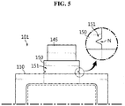
- FIG. 5 is a top view of the pouch type secondary battery according to an embodiment of the present disclosure.
- a surplus part 151 may be formed by increasing the length of the lead film 150 extending out from the pouch case 110 of the pouch type secondary battery 101.
- the surplus part 151 may cover the length extended part 141. That is, an increase in the area in which the electrode leads 140, 145 are covered by the lead film 150 ensures insulation.
- the surplus part 151 may be removed.
- a notch N may be formed on two sides of the lead film 150. Instead of the notch N, a perforated line may be formed by punching, or a cutout corresponding to the perforated line may be formed beforehand.
- a plurality of notches N may be formed as shown, and only one notch N may be formed.
- the notch N may be in semicircular, circular, U or V shape.
- the notch N may be included in two sides of the lead film 150 extending out from the pouch case 110.
- the lead film 150 may prevent a short circuit from occurring between the electrode lead 140, 145 and a metal layer of the pouch case 110, as well as improving the sealing of the pouch case 110.
- the contact resistance is somewhat large, causing the surface contact to reduce.
- the lead film 150 is made of an insulating material to prevent the application of the current from the electrode leads 140, 145 to the pouch case 110.
- the lead film 150 is formed of a film with insulation and heat weldability.
- the lead film 150 may be formed of, for example, a layer (a single layer or a multiple layer) of at least one material selected from polyimide (PI), polypropylene (PP), polyethylene (PE) and polyethylene terephthalate (PET).
- PI polyimide
- PP polypropylene
- PE polyethylene
- PET polyethylene terephthalate
- the lead film 150 serves to prevent a short circuit in exposed parts of the electrode leads 140, 145 through the pouch case 110 by increasing the length of the lead film 150.
- the pouch type secondary battery 101 has an increase in the length of the electrode leads 140, 145 and the length of the lead film 150, taking into account a length that is cut and removed when reusing and a length of a part to be additionally welded, and the reusable battery module 111 includes the pouch type secondary battery 101.
- FIG. 6 is a top view of the pouch type secondary battery according to another embodiment of the present disclosure.
- an additional insulation tape 155 is attached onto the lead film 150 or the electrode leads 140, 145 extending out from the pouch case 110 of the pouch type secondary battery, ensuring insulation of the electrode leads 140, 145 with the increased length.
- the insulation tape 155 may cover the length extended part 141.
- the insulation tape 155 may be PI or PP.
- the insulation tape 155 may be a composite film in which a PI or PP film has an adhesive layer such as an epoxy adhesive.
- the additional insulation tape 155 provides an additional insulating portion to prevent a potential insulation problem caused by the long electrode leads 140, 145.
- the insulation tape 155 (and even a surplus part if the lead film has the surplus part) may be removed.
- the insulation tape 155 may be removed from the electrode leads 140, 145 through a simple operation of peeling off.
- FIG. 7 is a side view illustrating a method of reusing a battery module including the pouch type secondary batteries shown in FIG. 5 .
- FIG. 8 is a top view showing preparation before step (a) in FIG. 7 .
- the battery module 111 has a wide range of applications, and for example, may be used as a power source for at least one medium- and large-scale device of power tools; electric cars including electric vehicles (EVs), hybrid electric vehicles (HEVs), and plug-in hybrid electric vehicles (PHEVs); electric truck; electric commercial vehicles; and energy storage systems.
- EVs electric vehicles
- HEVs hybrid electric vehicles
- PHEVs plug-in hybrid electric vehicles
- electric truck electric commercial vehicles
- energy storage systems energy storage systems.
- the welded part A of the electrode leads 140, 145 is cut along a line C from the conventional battery module 111 as shown in (a). In this instance, it may start with preparation shown in FIG. 8 . That is, the surplus part 151 described in FIG. 5 or the insulation tape 155 described in FIG. 6 is removed first, leaving a lead film 150' extending out from the pouch case 110 as much as a normal length, and then step (a) of FIG. 7 may be performed. The step of removing the surplus part 151 described in FIG. 5 or the insulation tape 155 described in FIG. 6 may be performed before or after step (a) or (b) of FIG. 7 .
- the pouch type secondary batteries 101 are re-arranged as shown in (b), and as shown in (c), the remaining electrode leads 140', 145' are newly welded L' to each other to manufacture a different, new battery module 211. Specifically, after the remaining electrode leads 140', 145' are used as they are and a new structure 165 is placed, the remaining electrode leads 140', 145' are bent and welding L' is performed with the bent parts brought into contact. Then, the pouch type secondary batteries 101 may be re-arranged and re-constructed for reuse as a new battery module 211.
- the space occupied by the electrode leads in the battery module increases in initial use, exerting negative influence such as area ratio reduction.
- the size of the length extended part 141 may be selected, taking this area ratio into account as much as possible, but it will be more desirable if the battery module is reused without changing the area ratio.
- the next embodiment relates to a method of reusing a battery module without increasing the electrode lead length.
- FIG. 9 is a side view illustrating a method of reusing a battery module according to another embodiment of the present disclosure.
- FIG. 9 shows side view of a battery module including conventional pouch type secondary batteries, for example, the general battery module 11 such as that shown in FIG. 2 .
- the welded part A is cut along a line C into the state of (b).
- the remaining electrode leads 40', 45' are too short to use as they are.
- the present disclosure proposes welding L'" the additional leads 41, 46 for electrode lead length extension to the remaining electrode leads 40', 45' respectively.
- welding L" of the additional leads 41, 46 is performed to re-arrange and re-construct the pouch type secondary batteries 1 for reuse as a new battery module 311.
- the battery module without increasing the length of the electrode leads at the initial manufacture of the battery module. Rather, because a minimum length for welding the additional leads after cutting the welded part is required, it is more preferable to increase the electrode lead length even a little bit longer than those of commonly used general pouch type secondary batteries.
- welding L'" the additional leads 41, 46 for electrode lead length extension to the remaining electrode leads 40', 45' respectively, many welding methods may be used, and when friction stir welding is used, it is advantageous because the weld width is less than 1mm.
- the friction stir welding is a welding method that heats and softens targets (in this embodiment, the additional leads 41, 46 and the remaining electrode leads 40', 45') by heat generated by friction by inserting a tool into the target and rotating the tool and stirring of the tool, leading to plastic flow, and welds the targets by the solid state joining, for example, welds the targets together at the joined area.
- the friction stir welding is a method that joins the additional leads 41, 46 and the remaining electrode leads 40', 45' in solid state without melting, and an advantage is that the characteristics of the welded part are better than fusion welding.
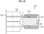
- FIG. 10 is a side view of a battery module including pouch type secondary batteries according to still another embodiment of the present disclosure.
- this is a case of increasing the electrode lead length for reuse by connecting the pouch type secondary batteries with the remaining electrode lead part after cutting the welded part after use of the battery module.
- the pouch type secondary battery 101 described with reference to FIG. 4 is included in a battery module 121.
- the plurality of pouch type secondary batteries 101 is stacked, and two adjacent pouch type secondary batteries 101 are connected in series and/or in parallel such that the electrode leads 140, 145 provided in each pouch type secondary battery 101 are connected to each other to construct a battery module 121 with improved capacity and output.
- the reference numeral 160 is a structure that structurally supports the battery module 121, such as a molded product, in the same way as described previously.
- the electrode leads 140, 145 are respectively welded to the positive electrode tab and the negative electrode tab of the electrode assembly and exposed through the pouch case 110. A portion where the electrode leads 140, 145 are drawn is called terrace T.
- this embodiment is characterized in that the length increased electrode leads 140, 145 are folded into the terrace T of the pouch type secondary battery 101 to reduce the horizontal length.
- an insulation ensuring structure is needed, and is indicated by the reference numeral 170 in the drawing.
- the insulation ensuring structure 170 may be formed by providing the length increased lead film 150 having the surplus part 151 or the insulation tape 155 and folding the electrode leads 140, 145 neatly, and winding another insulating tape after folding the electrode leads 140, 145.
- the battery module 121 with the structure of FIG.
- the 10 may have a shape change or more complex shape of counterpart (for example, a cartridge, etc.) for fixing the pouch type secondary batteries 101 to fixedly receive the electrode leads 140, 145 folded into the terrace T in overlapping manner, but preferably ensures spatial utility / insulation / secondary utility possibility.
- counterpart for example, a cartridge, etc.
- FIG. 11 is a side view illustrating a method of reusing the battery module of FIG. 10 .
- the welded part A is cut along a line C as shown in (a), and the folded electrode leads are unfolded as shown in (b).
- the electrode leads 140', 145' are bent as shown in (c), and the structure 165 is placed and the electrode leads 140', 145' are welded L" to re-arrange and re-construct the pouch type secondary batteries 101 for reuse as a new battery module 211.
- the methods of reusing by combining or applying the previously described embodiments are available.
- the insufficient electrode lead length problem encountered when reusing pouch type secondary batteries is solved, and a battery module of a new connection structure may be constructed irrespective of series/parallel connections structure.
- the present disclosure proposes a method of reusing a battery module.
- the initial battery module is used, for example, as an electric vehicle battery, and after the intended service life expires, may be manufactured into another battery module by re-arranging and re-welding pouch type secondary batteries through the reuse method proposed by the present disclosure.
- the newly manufactured battery module may be used for a second purpose, for example, an ESS having less strict capacity retention or other conditions than an electric vehicle battery.
- it is possible to reuse without wasting the limited resources through the reuse of the battery module, and there are eco-friendly and cost effective advantages.
Landscapes
- Chemical & Material Sciences (AREA)
- Chemical Kinetics & Catalysis (AREA)
- Electrochemistry (AREA)
- General Chemical & Material Sciences (AREA)
- Engineering & Computer Science (AREA)
- Manufacturing & Machinery (AREA)
- Inorganic Chemistry (AREA)
- Battery Mounting, Suspending (AREA)
- Secondary Cells (AREA)
- Connection Of Batteries Or Terminals (AREA)
- Sealing Battery Cases Or Jackets (AREA)
- Cell Separators (AREA)
Abstract
Description
- The present disclosure relates to a pouch type secondary battery, and more particularly, to a reusable pouch type secondary battery and a battery module comprising the same. The present disclosure also relates to a method of reusing the battery module and a method of reusing a general battery module. The present application claims priority to Korean Patent Application No.
10-2017-0052906 - Recently, with the dramatically increasing demand for portable electronic products such as laptop computers, video cameras, mobile phones, and the like, along with the active development of electric vehicles, accumulators for energy storage, robots, satellites, and the like, many studies of high-performance secondary batteries capable of repeatedly recharging has been conducted. Currently, among commercially available secondary batteries, lithium secondary batteries have little or no memory effect, and thus they are gaining more attention than nickel-based secondary batteries for their advantages of free charging/discharging, low self-discharging, and high energy density.
- More recently, secondary batteries are being widely used in not only small devices such as portable electronic products but also medium- and large-scale devices such as vehicles and energy storage systems (ESSs). In particular, with the steady exhaustion of carbon energy and increasing interest in the environment, the demand for hybrid electric vehicles and electric vehicles is increasing all over the world including United States, Europe, Japan, and the Republic of Korea. In such hybrid electric vehicles or electric vehicles, the most essential component is a battery pack that gives a driving power to an automobile motor. Because hybrid electric vehicles or electric vehicles are supplied with power for driving the vehicles through charging/discharging of battery packs, as compared to vehicles powered by an engine alone, they have higher fuel efficiency and can eliminate or lessen the emission of pollutants, and by this reason, the number of users is now increasing.
- When a secondary battery is used for an electric vehicle, to increase the capacity and output, a battery pack is manufactured using battery modules in which many secondary batteries are connected in series and/or in parallel. In this instance, pouch type secondary batteries are widely used in medium- and large-scale devices because they are easy to stack.
-
FIG. 1 shows a general pouch type secondary battery. - Referring to
FIG. 1 , the general pouch typesecondary battery 1 has a sealingpart 30 formed by sealing apouch case 10 in which anelectrode assembly 20 is received, and electrode leads 40, 45 are welded to a positive electrode tab and a negative electrode tab of theelectrode assembly 20 respectively and exposed through thepouch case 10. Alead film 50 is interposed between thepouch case 10 and the electrode leads 40, 45. In the sealingpart 30, particularly, a portion where the electrode leads 40, 45 are drawn is called terrace T. - As shown in
FIG. 2 , a plurality of pouch typesecondary batteries 1 is stacked, and two adjacent pouch typesecondary batteries 1 are connected in series and/or in parallel such that the electrode leads 40, 45 provided in each pouch typesecondary battery 1 are connected to each other to construct abattery module 11 with improved capacity and output. Thereference numeral 60 is a structure that structurally supports thebattery module 11, such as a molded product. - When connecting the pouch type
secondary batteries 1 to manufacture thebattery module 11, laser welding L is applied to connect the electrode leads 40, 45. Thebattery module 11 is used for an automobile battery, and after the intended service life expires, it would be desirable that thebattery module 11 is used for a second purpose, for example, an ESS having less strict capacity retention rate or other conditions. To this end, it is necessary to dissemble the existing connection structure of the first battery module and connect the pouch type secondary batteries by a different method to manufacture a new battery module for the purpose of reuse. However, conventionally, it was not easy to reuse because it was impossible to separate the electrode leads 40, 45 joined by laser welding L using a non-destructive method. - As in
FIG. 3 , when a welded part A formed by laser welding L is cut along a line C, the remaining electrode leads 40', 45' are too short. By this reason, it is impossible to reuse by reconnection and welding only using the remaining electrode leads 40', 45'. - As described above, conventionally, when disassembling a battery module and reusing pouch type secondary batteries for a new battery module, insufficient electrode lead length is problematic.
- The present disclosure is designed to solve the above-described problem, and therefore the present disclosure is directed to providing a reusable pouch type secondary battery.
- The present disclosure is further directed to providing a reusable battery module.
- The present disclosure is further directed to providing a method of reusing a battery module.
- These and other objects and advantages of the present disclosure will be understood by the following description and will be apparent from the embodiments of the present disclosure. Further, it will be readily understood that the objects and advantages of the present disclosure are realized by the means set forth in the appended claims and combinations thereof.
- To achieve the above-described object, a pouch type secondary battery according to the present disclosure is a pouch type secondary battery in which an electrode lead of the pouch type secondary battery and an electrode lead of an adjacent different pouch type secondary battery are welded to construct a battery module, and the electrode lead includes a length extended part so that the electrode leads of remaining length after cutting a welded part of the electrode leads are welded again.
- According to an embodiment of the present disclosure, the pouch type secondary battery has a lead film between a pouch case and the electrode lead, and the lead film may include a surplus part so that the lead film is formed to the length extended part. In this instance, the lead film may include a notch on two sides of a part sticking out of the pouch case to remove the surplus part.
- According to another embodiment of the present disclosure, the pouch type secondary battery further includes an insulation tape that covers the length extended part. The insulation tape may be a composite film in which a PI or PP film has an adhesive layer.
- To achieve another object, a battery module according to the present disclosure includes the pouch type secondary battery.
- The battery module according to the present disclosure includes a plurality of stacked pouch type secondary batteries, each having an electrode lead including a length extended part, so that electrode leads of remaining length after cutting a welded part of the electrode leads are welded again, with the electrode leads of adjacent pouch type secondary batteries being welded.
- According to another embodiment of the present disclosure, the electrode lead of the pouch type secondary battery included in the battery module is folded into terrace of the pouch type secondary battery. The battery module may further include another insulation tape on a part where the electrode lead is folded.
- To achieve still another object, a method of reusing a battery module according to the present disclosure is a method of reusing the battery module according to the present disclosure.
- An embodiment of the method of reusing a battery module according to the present disclosure is a method of reusing a battery module, in which a plurality of pouch type secondary batteries is stacked, each having an electrode lead including a length extended part, so that electrode leads of remaining length after cutting a welded part of the electrode leads are welded again, and the electrode leads of adjacent pouch type secondary batteries are welded, the reuse method including cutting the welded part of the battery module, and re-arranging the pouch type secondary batteries and welding the remaining electrode leads to manufacture another battery module.
- When the pouch type secondary battery has a lead film between a pouch case and the electrode lead, the lead film includes a surplus part so that the lead film is formed to the length extended part, and the lead film includes a notch on two sides of a part sticking out of the pouch case to remove the surplus part, the reuse method may further include removing the surplus part before or after cutting the welded part of the battery module.
- When the pouch type secondary battery further includes an insulation tape that covers the length extended part, the reuse method may further include removing the insulation tape before or after cutting the welded part of the battery module.
- Another embodiment of a method of reusing a battery module according to the present disclosure is a method of reusing a battery module, in which a plurality of pouch type secondary batteries is stacked, each having an electrode lead including a length extended part, so that electrode leads of remaining length after cutting a welded part of the electrode leads are welded again, and the electrode leads are welded and folded into terrace of the pouch type secondary battery, the reuse method including cutting the welded part of the battery module, unfolding the folded electrode leads, and re-arranging the pouch type secondary batteries and welding the unfolded electrode leads to manufacture another battery module.
- Further, the present disclosure proposes a method of reusing a general battery module. The reuse method is a method of reusing a battery module, in which a plurality of pouch type secondary batteries are stacked and electrode leads of adjacent pouch type secondary batteries are welded, the reuse method including cutting a welded part of the electrode leads, welding additional leads for electrode lead length extension to the remaining electrode leads respectively, and re-arranging the pouch type secondary batteries and welding the additional leads to manufacture another battery module.
- Here, the step of welding additional leads for electrode lead length extension to the remaining electrode leads respectively is preferably performed by friction stir welding.
- According to the present disclosure, by solving the insufficient electrode lead length problem when reusing pouch type secondary batteries, a battery module of a new connection structure may be constructed, no matter which connection structure is series or parallel.
- According to an aspect of the present disclosure, it is possible to reuse the battery module through structure modification to increase the electrode lead length of the pouch type secondary batteries. Because the remaining electrode lead length after cutting the joined part by laser welding is enough long, the pouch type secondary batteries may be used for a second purpose after connected again.
- According to another aspect of the present disclosure, it is possible to reuse a battery module including conventional pouch type secondary batteries by joining additional leads to the battery module to extend the electrode lead length, the battery module may be reused.
- According to still another aspect of the present disclosure, while the electrode lead length of the pouch type secondary batteries is increased, the electrode leads are folded for space utilization. The battery module may be reused for a second purpose, for example, an ESS, by unfolding the folded electrode leads and changing the series/parallel connection structure of the pouch type secondary batteries.
- As above, according to the present disclosure, it is easy to reuse a battery module including pouch type secondary batteries, contributing to the utilization of limited resources and maximizing cost efficiency.
- The accompanying drawings illustrate preferred embodiments of the present disclosure and together with the following detailed description, serve to provide further understanding of the technical aspects of the present disclosure, and thus, the present disclosure should not be construed as being limited to the drawings.
-
FIG. 1 is a schematic diagram showing a general pouch type secondary battery. -
FIG. 2 is a side view of a conventional battery module. -
FIG. 3 is a diagram showing that it is difficult to reuse pouch type secondary batteries in a conventional battery module. -
FIG. 4 is a side view of a battery module including pouch type secondary batteries according to an embodiment of the present disclosure. -
FIG. 5 is a top view of a pouch type secondary battery according to an embodiment of the present disclosure. -
FIG. 6 is a top view of a pouch type secondary battery according to another embodiment of the present disclosure. -
FIG. 7 is a side view illustrating a method of reusing a battery module including the pouch type secondary batteries shown inFIG. 5 . -
FIG. 8 is a top view showing preparation before step (a) inFIG. 7 . -
FIG. 9 is a side view illustrating a reuse method according to another embodiment of the present disclosure. -
FIG. 10 is a side view of a battery module including pouch type secondary batteries according to still another embodiment of the present disclosure. -
FIG. 11 is a side view illustrating a method of reusing the battery module ofFIG. 10 . - Hereinafter, the preferred embodiments of the present disclosure will be described in detail with reference to the accompanying drawings. Prior to the description, it should be understood that the terms or words used in the specification and the appended claims should not be construed as limited to general and dictionary meanings, but interpreted based on the meanings and concepts corresponding to the technical aspects of the present disclosure on the basis of the principle that the inventor is allowed to define terms appropriately for the best explanation.
- Therefore, the embodiments described herein and illustrations shown in the drawings are just a most preferred embodiment of the present disclosure, but not intended to fully describe the technical aspects of the present disclosure, so it should be understood that other equivalents and modifications could be made thereto at the time the application was filed.
-
FIG. 4 is a side view of a battery module including pouch type secondary batteries according to an embodiment of the present disclosure. - Referring to
FIG. 4 , a plurality of pouch typesecondary batteries 101 is stacked, and two adjacent pouch typesecondary batteries 101 are connected in series and/or in parallel such that electrode leads 140, 145 provided in each pouch typesecondary battery 101 are connected to each other to construct abattery module 111. Thereference numeral 160 is a structure that structurally supports thebattery module 111, such as a molded product, and thereference numeral 150 is a lead film. The outline of the pouch typesecondary battery 101 is similar to that of the pouch typesecondary battery 1 ofFIG. 1 , and an electrode assembly is received in apouch case 110 and sealed to form a sealing part, and the electrode leads 140, 145 are each welded to the positive electrode tab and the negative electrode tab of the electrode assembly and exposed through thepouch case 110. Thelead film 150 is interposed between thepouch case 110 and theelectrode lead - The electrode leads 140, 145 have the increased length compared to the electrode leads 40, 45 of the conventional pouch type
secondary battery 1 described with reference toFIGS. 1 to 3 . The electrode leads 140, 145 include a lengthextended part 141 so that the electrode leads of the remaining length after cutting a welded part A of the electrode leads 140, 145 can be welded again. The size d of the length extendedpart 141 may be determined, taking into account a length that is discarded when cutting the welded part and a length and processing allowance required when newly welding, and when a currently used welder and the structure of the pouch type secondary battery are taken into account, preferably the size of the length extendedpart 141 is approximately 7mm or more. When the length extended part d is smaller than 7mm or less, there is difficulty in aligning the welder to weld the remaining parts after cutting the electrode leads 140, 145. When the length extendedpart 141 is too large, the spatial volume of thebattery module 111 increases due to the electrode leads 140, 145, and when the energy density is considered, it is unfavorable. In view of this circumstance, the size d of the length extendedpart 141 is preferably 8mm or more and 15mm or less. - The pouch type
secondary battery 101 according to an embodiment of the present disclosure has the increased length of the electrode leads 140, 145 compared to the conventional one, so that after use of thebattery module 111, the pouch typesecondary batteries 101 can be connected and reused by welding the remaining electrode lead parts after cutting the welded part A of the electrode leads 140, 145. As described above, the present disclosure proposes manufacturing the pouch typesecondary battery 101 with the increased length of the electrode leads 140, 145 compared to the conventional one, stacking the pouch typesecondary batteries 101, bending eachelectrode lead battery module 111. That is, thebattery module 111 according to the present disclosure is manufactured by stacking the plurality of pouch typesecondary batteries 101 having the electrode leads 140, 145 including the length extendedpart 141 so that the electrode leads of the remaining length after cutting the welded part A of the electrode leads 140, 145 can be welded again, and welding the electrode leads 140, 145 of adjacent pouch typesecondary batteries 101. - Because of including the length extended
part 141, the battery module with the increased length of the electrode leads 140, 145 compared to the conventional one has a short circuit problem in the event of unwanted contact between the electrode leads 140, 145 with the increased length. The present disclosure ensures insulation by increasing the length of the insulatingfilm 150 to cover the length extendedpart 141. -
FIG. 5 is a top view of the pouch type secondary battery according to an embodiment of the present disclosure. - To solve the insulation problem encountered when using the
battery module 111 due to the electrode leads 140, 145 with the increased length, asurplus part 151 may be formed by increasing the length of thelead film 150 extending out from thepouch case 110 of the pouch typesecondary battery 101. Thesurplus part 151 may cover the length extendedpart 141. That is, an increase in the area in which the electrode leads 140, 145 are covered by thelead film 150 ensures insulation. After thebattery module 111 is used, thesurplus part 151 may be removed. To easily remove thesurplus part 151, a notch N may be formed on two sides of thelead film 150. Instead of the notch N, a perforated line may be formed by punching, or a cutout corresponding to the perforated line may be formed beforehand. - A plurality of notches N may be formed as shown, and only one notch N may be formed. The notch N may be in semicircular, circular, U or V shape. The notch N may be included in two sides of the
lead film 150 extending out from thepouch case 110. - The
lead film 150 may prevent a short circuit from occurring between theelectrode lead pouch case 110, as well as improving the sealing of thepouch case 110. In the heat welding of the electrode leads 140, 145 made of metal and thepouch case 110 made of polymer, the contact resistance is somewhat large, causing the surface contact to reduce. However, as in the above embodiment, with thelead film 150, this contact reduction phenomenon may be prevented. Additionally, it is preferred that thelead film 150 is made of an insulating material to prevent the application of the current from the electrode leads 140, 145 to thepouch case 110. Thelead film 150 is formed of a film with insulation and heat weldability. Thelead film 150 may be formed of, for example, a layer (a single layer or a multiple layer) of at least one material selected from polyimide (PI), polypropylene (PP), polyethylene (PE) and polyethylene terephthalate (PET). In this embodiment, thelead film 150 serves to prevent a short circuit in exposed parts of the electrode leads 140, 145 through thepouch case 110 by increasing the length of thelead film 150. - The pouch type
secondary battery 101 according to an embodiment of the present disclosure has an increase in the length of the electrode leads 140, 145 and the length of thelead film 150, taking into account a length that is cut and removed when reusing and a length of a part to be additionally welded, and thereusable battery module 111 includes the pouch typesecondary battery 101. -
FIG. 6 is a top view of the pouch type secondary battery according to another embodiment of the present disclosure. - Referring to
FIG. 6 , anadditional insulation tape 155 is attached onto thelead film 150 or the electrode leads 140, 145 extending out from thepouch case 110 of the pouch type secondary battery, ensuring insulation of the electrode leads 140, 145 with the increased length. Theinsulation tape 155 may cover the length extendedpart 141. Additionally, theinsulation tape 155 may be PI or PP. Specifically, theinsulation tape 155 may be a composite film in which a PI or PP film has an adhesive layer such as an epoxy adhesive. Theadditional insulation tape 155 provides an additional insulating portion to prevent a potential insulation problem caused by the long electrode leads 140, 145. After use of thebattery module 111, the insulation tape 155 (and even a surplus part if the lead film has the surplus part) may be removed. Theinsulation tape 155 may be removed from the electrode leads 140, 145 through a simple operation of peeling off. -
FIG. 7 is a side view illustrating a method of reusing a battery module including the pouch type secondary batteries shown inFIG. 5 .FIG. 8 is a top view showing preparation before step (a) inFIG. 7 . - The
battery module 111 has a wide range of applications, and for example, may be used as a power source for at least one medium- and large-scale device of power tools; electric cars including electric vehicles (EVs), hybrid electric vehicles (HEVs), and plug-in hybrid electric vehicles (PHEVs); electric truck; electric commercial vehicles; and energy storage systems. After the service life expires after use as intended, thebattery module 111 may be reused through the reuse method according to the present disclosure. - Referring to
FIG. 7 , for reuse, first, the welded part A of the electrode leads 140, 145 is cut along a line C from theconventional battery module 111 as shown in (a). In this instance, it may start with preparation shown inFIG. 8 . That is, thesurplus part 151 described inFIG. 5 or theinsulation tape 155 described inFIG. 6 is removed first, leaving a lead film 150' extending out from thepouch case 110 as much as a normal length, and then step (a) ofFIG. 7 may be performed. The step of removing thesurplus part 151 described inFIG. 5 or theinsulation tape 155 described inFIG. 6 may be performed before or after step (a) or (b) ofFIG. 7 . - After the welded part A is cut as shown in (a) of
FIG. 7 , the pouch typesecondary batteries 101 are re-arranged as shown in (b), and as shown in (c), the remaining electrode leads 140', 145' are newly welded L' to each other to manufacture a different,new battery module 211. Specifically, after the remaining electrode leads 140', 145' are used as they are and anew structure 165 is placed, the remaining electrode leads 140', 145' are bent and welding L' is performed with the bent parts brought into contact. Then, the pouch typesecondary batteries 101 may be re-arranged and re-constructed for reuse as anew battery module 211. - Meanwhile, when the length of the electrode leads increases as described in
FIG. 4 , the space occupied by the electrode leads in the battery module increases in initial use, exerting negative influence such as area ratio reduction. The size of the length extendedpart 141 may be selected, taking this area ratio into account as much as possible, but it will be more desirable if the battery module is reused without changing the area ratio. The next embodiment relates to a method of reusing a battery module without increasing the electrode lead length. -
FIG. 9 is a side view illustrating a method of reusing a battery module according to another embodiment of the present disclosure. - (a) of
FIG. 9 shows side view of a battery module including conventional pouch type secondary batteries, for example, thegeneral battery module 11 such as that shown inFIG. 2 . After use of thebattery module 11 as originally intended, the welded part A is cut along a line C into the state of (b). The remaining electrode leads 40', 45' are too short to use as they are. The present disclosure proposes welding L'" the additional leads 41, 46 for electrode lead length extension to the remaining electrode leads 40', 45' respectively. After extending the electrode lead length, referring to (c), for bending of the additional leads 41, 46, placement of thestructure 165 and construction of a new battery module, welding L" of the additional leads 41, 46 is performed to re-arrange and re-construct the pouch typesecondary batteries 1 for reuse as anew battery module 311. - According to this embodiment, it is possible reuse the battery module without increasing the length of the electrode leads at the initial manufacture of the battery module. Rather, because a minimum length for welding the additional leads after cutting the welded part is required, it is more preferable to increase the electrode lead length even a little bit longer than those of commonly used general pouch type secondary batteries. When welding L'" the additional leads 41, 46 for electrode lead length extension to the remaining electrode leads 40', 45' respectively, many welding methods may be used, and when friction stir welding is used, it is advantageous because the weld width is less than 1mm.
- The friction stir welding is a welding method that heats and softens targets (in this embodiment, the additional leads 41, 46 and the remaining electrode leads 40', 45') by heat generated by friction by inserting a tool into the target and rotating the tool and stirring of the tool, leading to plastic flow, and welds the targets by the solid state joining, for example, welds the targets together at the joined area. The friction stir welding is a method that joins the additional leads 41, 46 and the remaining electrode leads 40', 45' in solid state without melting, and an advantage is that the characteristics of the welded part are better than fusion welding.
-
FIG. 10 is a side view of a battery module including pouch type secondary batteries according to still another embodiment of the present disclosure. - Referring to
FIG. 10 , in the same way as the first embodiment, this is a case of increasing the electrode lead length for reuse by connecting the pouch type secondary batteries with the remaining electrode lead part after cutting the welded part after use of the battery module. - That is, the pouch type
secondary battery 101 described with reference toFIG. 4 is included in abattery module 121. The plurality of pouch typesecondary batteries 101 is stacked, and two adjacent pouch typesecondary batteries 101 are connected in series and/or in parallel such that the electrode leads 140, 145 provided in each pouch typesecondary battery 101 are connected to each other to construct abattery module 121 with improved capacity and output. Thereference numeral 160 is a structure that structurally supports thebattery module 121, such as a molded product, in the same way as described previously. - The electrode leads 140, 145 are respectively welded to the positive electrode tab and the negative electrode tab of the electrode assembly and exposed through the
pouch case 110. A portion where the electrode leads 140, 145 are drawn is called terrace T. - In this instance, this embodiment is characterized in that the length increased electrode leads 140, 145 are folded into the terrace T of the pouch type
secondary battery 101 to reduce the horizontal length. To prevent a potential risk of a short circuit between the electrode leads 140, 145 that are folded and overlap with the terrace T, an insulation ensuring structure is needed, and is indicated by thereference numeral 170 in the drawing. As described previously, theinsulation ensuring structure 170 may be formed by providing the length increasedlead film 150 having thesurplus part 151 or theinsulation tape 155 and folding the electrode leads 140, 145 neatly, and winding another insulating tape after folding the electrode leads 140, 145. Thebattery module 121 with the structure ofFIG. 10 may have a shape change or more complex shape of counterpart (for example, a cartridge, etc.) for fixing the pouch typesecondary batteries 101 to fixedly receive the electrode leads 140, 145 folded into the terrace T in overlapping manner, but preferably ensures spatial utility / insulation / secondary utility possibility. -
FIG. 11 is a side view illustrating a method of reusing the battery module ofFIG. 10 . After use of thebattery module 121, the welded part A is cut along a line C as shown in (a), and the folded electrode leads are unfolded as shown in (b). Subsequently, the electrode leads 140', 145' are bent as shown in (c), and thestructure 165 is placed and the electrode leads 140', 145' are welded L" to re-arrange and re-construct the pouch typesecondary batteries 101 for reuse as anew battery module 211. - Of course, the methods of reusing by combining or applying the previously described embodiments are available. As described above, according to the present disclosure, the insufficient electrode lead length problem encountered when reusing pouch type secondary batteries is solved, and a battery module of a new connection structure may be constructed irrespective of series/parallel connections structure.
- As described above, the present disclosure proposes a method of reusing a battery module. The initial battery module is used, for example, as an electric vehicle battery, and after the intended service life expires, may be manufactured into another battery module by re-arranging and re-welding pouch type secondary batteries through the reuse method proposed by the present disclosure. The newly manufactured battery module may be used for a second purpose, for example, an ESS having less strict capacity retention or other conditions than an electric vehicle battery. As described above, according to the present disclosure, it is possible to reuse without wasting the limited resources through the reuse of the battery module, and there are eco-friendly and cost effective advantages.
- While the present disclosure has been hereinabove described with regard to a limited number of embodiments and drawings, the present disclosure is not limited thereto and it is obvious to those skilled in the art that various modifications and changes may be made thereto within the technical aspects of the present disclosure and the equivalent scope of the appended claims.
Claims (15)
- A pouch type secondary battery, wherein an electrode lead of the pouch type secondary battery and an electrode lead of an adjacent different pouch type secondary battery are welded to construct a battery module, and
the electrode lead includes a length extended part so that the electrode leads of remaining length after cutting a welded part of the electrode leads are welded again. - The pouch type secondary battery according to claim 1, wherein the pouch type secondary battery has a lead film between a pouch case and the electrode lead, and the lead film includes a surplus part so that the lead film is formed to the length extended part.
- The pouch type secondary battery according to claim 2, wherein the lead film includes a notch on two sides of a part sticking out of the pouch case to remove the surplus part.
- The pouch type secondary battery according to claim 1, wherein further comprises an insulation tape that covers the length extended part.
- A battery module comprising:
a plurality of stacked pouch type secondary batteries, each having an electrode lead including a length extended part, so that electrode leads of remaining length after cutting a welded part of the electrode leads are welded again, with the electrode leads of adjacent pouch type secondary batteries being welded. - The battery module according to claim 5, wherein the electrode lead is folded into terrace of the pouch type secondary battery.
- The battery module according to claim 5 or 6, wherein the pouch type secondary battery has a lead film between a pouch case and the electrode lead, and the lead film includes a surplus part so that the lead film is formed to the length extended part.
- The battery module according to claim 7, wherein the lead film includes a notch on two sides of a part sticking out of the pouch case to remove the surplus part.
- The battery module according to claim 5 or 6, wherein further comprises an insulation tape that covers the length extended part.
- The battery module according to claim 6, wherein further comprises another insulation tape on a part where the electrode lead is folded.
- A method of reusing a battery module, in which a plurality of pouch type secondary batteries is stacked, each having an electrode lead including a length extended part, so that electrode leads of remaining length after cutting a welded part of the electrode leads are welded again, and the electrode leads of adjacent pouch type secondary batteries are welded, the reuse method comprising:cutting the welded part of the battery module; andre-arranging the pouch type secondary batteries and welding the remaining electrode leads to manufacture another battery module.
- The reuse method according to claim 11, wherein the pouch type secondary battery has a lead film between a pouch case and the electrode lead, the lead film includes a surplus part so that the lead film is formed to the length extended part, and the lead film includes a notch on two sides of a part sticking out of the pouch case to remove the surplus part, and
the reuse method further comprises removing the surplus part before or after cutting the welded part of the battery module. - The reuse method according to claim 11, wherein the pouch type secondary battery further includes an insulation tape that covers the length extended part, and
the reuse method further comprises removing the insulation tape before or after cutting the welded part of the battery module. - A method of reusing a battery module, in which a plurality of pouch type secondary batteries is stacked, each having an electrode lead including a length extended part, so that electrode leads of remaining length after cutting a welded part of the electrode leads are welded again, and the electrode leads are welded and folded into terrace of the pouch type secondary battery, the reuse method comprising:cutting the welded part of the battery module;unfolding the folded electrode leads; andre-arranging the pouch type secondary batteries and welding the unfolded electrode leads to manufacture another battery module.
- A method of reusing a battery module, in which a plurality of pouch type secondary batteries are stacked and electrode leads of adjacent pouch type secondary batteries are welded, the reuse method comprising:cutting a welded part of the electrode leads;welding additional leads for electrode lead length extension to the remaining electrode leads respectively; andre-arranging the pouch type secondary batteries and welding the additional leads to manufacture another battery module.
Priority Applications (1)
| Application Number | Priority Date | Filing Date | Title |
|---|---|---|---|
| PL18791492T PL3573139T3 (en) | 2017-04-25 | 2018-02-19 | Reuseable pouch type secondary battery, battery module comprising the same and method of reusing battery module |
Applications Claiming Priority (2)
| Application Number | Priority Date | Filing Date | Title |
|---|---|---|---|
| KR1020170052906A KR102258822B1 (en) | 2017-04-25 | 2017-04-25 | Reusable pouch type secondary battery, battery module comprising the same and method of reusing battery module |
| PCT/KR2018/002006 WO2018199449A1 (en) | 2017-04-25 | 2018-02-19 | Recyclable pouch-type secondary battery, battery module comprising same, and battery module recycling method |
Publications (3)
| Publication Number | Publication Date |
|---|---|
| EP3573139A1 true EP3573139A1 (en) | 2019-11-27 |
| EP3573139A4 EP3573139A4 (en) | 2020-03-04 |
| EP3573139B1 EP3573139B1 (en) | 2022-04-06 |
Family
ID=63918410
Family Applications (1)
| Application Number | Title | Priority Date | Filing Date |
|---|---|---|---|
| EP18791492.4A Active EP3573139B1 (en) | 2017-04-25 | 2018-02-19 | Reuseable pouch type secondary battery, battery module comprising the same and method of reusing battery module |
Country Status (7)
| Country | Link |
|---|---|
| US (3) | US11362389B2 (en) |
| EP (1) | EP3573139B1 (en) |
| JP (1) | JP7027640B2 (en) |
| KR (1) | KR102258822B1 (en) |
| CN (1) | CN109891634B (en) |
| PL (1) | PL3573139T3 (en) |
| WO (1) | WO2018199449A1 (en) |
Families Citing this family (15)
| Publication number | Priority date | Publication date | Assignee | Title |
|---|---|---|---|---|
| US11545706B2 (en) * | 2018-06-19 | 2023-01-03 | Sk Innovation Co., Ltd. | Battery cell having a plurality of electrodes and battery module using the same |
| KR102452328B1 (en) * | 2019-01-10 | 2022-10-11 | 주식회사 엘지에너지솔루션 | Secondary battery and manufacturing method thereof |
| KR102779614B1 (en) | 2019-03-12 | 2025-03-10 | 주식회사 엘지에너지솔루션 | Battery module and method of manufacturing the same |
| CN110277582A (en) * | 2019-06-24 | 2019-09-24 | 福建卫东新能源股份有限公司 | A kind of rectangular cell and manufacturing method |
| KR102541537B1 (en) * | 2019-06-25 | 2023-06-08 | 주식회사 엘지에너지솔루션 | Battery module and battery pack including the same |
| CN111477800A (en) * | 2020-04-30 | 2020-07-31 | 昆山宝创新能源科技有限公司 | Battery Modules, Battery Packs and Vehicles |
| CN111477828A (en) * | 2020-04-30 | 2020-07-31 | 昆山宝创新能源科技有限公司 | Battery module and battery module and automobile having the same |
| CN120657338A (en) * | 2021-02-04 | 2025-09-16 | 株式会社Lg新能源 | Battery cell and battery module comprising same |
| DE102021108519B3 (en) * | 2021-04-06 | 2022-07-28 | Numbat Gmbh | Connection unit for electrically contacting at least two storage cells, storage unit and method |
| EP4170780A4 (en) * | 2021-09-02 | 2024-03-27 | Dongguan NVT Technology Limited | CELL, BATTERY, CELL MANUFACTURING METHOD AND ELECTRONIC DEVICE |
| KR102723746B1 (en) * | 2021-09-13 | 2024-10-31 | 주식회사 엘지에너지솔루션 | A pouch-type battery cell with a safety element between the electrode lead and the lead film |
| KR20240009718A (en) * | 2022-07-14 | 2024-01-23 | 주식회사 엘지에너지솔루션 | Battery module, battery pack and vehicle including the battery module |
| US20240079740A1 (en) * | 2022-09-02 | 2024-03-07 | Ford Global Technologies, Llc | Method of assembling traction battery pack and traction battery pack assembly |
| KR20240094615A (en) * | 2022-12-16 | 2024-06-25 | 주식회사 엘지에너지솔루션 | Battery cell with insulation film having a function for preventing short circuit by dew, and battery module comprising the same |
| CN121399761A (en) * | 2023-07-13 | 2026-01-23 | 松下知识产权经营株式会社 | Battery pack, method for manufacturing battery pack, and method for replacing secondary battery cell |
Family Cites Families (30)
| Publication number | Priority date | Publication date | Assignee | Title |
|---|---|---|---|---|
| CN1180506C (en) | 1999-03-26 | 2004-12-15 | 松下电器产业株式会社 | laminated sheet packaged battery |
| CN1186971C (en) * | 1999-04-22 | 2005-01-26 | 罗姆股份有限公司 | Circuit board, battery pack, and method of manufacturing circuit board |
| JP2005044583A (en) | 2003-07-25 | 2005-02-17 | Toshiba Corp | Thin secondary battery |
| NZ543486A (en) | 2005-11-10 | 2009-03-31 | Fonterra Corporate Res And Dev | Compositions of CIS-9, trans-11 conjugated linoleic acid and vaccenic acid and uses thereof |
| JP4904539B2 (en) | 2006-10-25 | 2012-03-28 | 住電朝日精工株式会社 | Lead member, bonding method thereof, and nonaqueous electrolyte storage device |
| KR20080096165A (en) * | 2007-04-27 | 2008-10-30 | 삼성에스디아이 주식회사 | Pouch type secondary battery and manufacturing method thereof |
| WO2008137178A1 (en) * | 2007-05-07 | 2008-11-13 | Georgia Tech Research Corporation | Containers having internal reinforcing structures |
| JP2010251085A (en) * | 2009-04-15 | 2010-11-04 | Nec Energy Devices Ltd | Multilayer secondary battery |
| CN101877413B (en) | 2009-04-30 | 2013-10-30 | 比亚迪股份有限公司 | Monomer battery and power battery pack containing same |
| JP5550093B2 (en) | 2009-06-26 | 2014-07-16 | Necエナジーデバイス株式会社 | Stacked laminated battery |
| JP5589534B2 (en) * | 2010-04-28 | 2014-09-17 | 日産自動車株式会社 | Flat battery |
| DE102010031457A1 (en) | 2010-07-16 | 2012-01-19 | Sb Limotive Company Ltd. | Method for producing electrically conductive connection between cells of e.g. lithium ion battery with propulsion system of motor car, involves applying opposite force on terminal against joining force to bring terminal in balance of forces |
| WO2012148100A2 (en) | 2011-04-26 | 2012-11-01 | 주식회사 엘지화학 | Bus bar having a novel structure, and battery module including same |
| JPWO2013094423A1 (en) * | 2011-12-22 | 2015-04-27 | 株式会社村田製作所 | Power storage device |
| JP5866463B2 (en) | 2012-02-29 | 2016-02-17 | エルジー・ケム・リミテッド | Battery cell assembly with improved safety and battery module including the same |
| JP2014035951A (en) * | 2012-08-09 | 2014-02-24 | Sanyo Electric Co Ltd | Nonaqueous electrolyte secondary battery |
| KR20140026104A (en) | 2012-08-24 | 2014-03-05 | 주식회사 엘지화학 | Battery module and method of manufacturing the same |
| JP6107091B2 (en) | 2012-12-04 | 2017-04-05 | 日産自動車株式会社 | Assembled battery and manufacturing method of assembled battery |
| KR20140145787A (en) * | 2013-06-14 | 2014-12-24 | 삼성에스디아이 주식회사 | Rechargeable battery pack |
| KR101671486B1 (en) | 2013-11-11 | 2016-11-01 | 주식회사 엘지화학 | Secondary Battery Including Fuse-equipped Electrode |
| KR101500229B1 (en) * | 2013-12-18 | 2015-03-06 | 현대자동차주식회사 | Apparatus for preventing over-charge for battery of vehicle |
| KR101558685B1 (en) | 2013-12-09 | 2015-10-07 | 현대자동차주식회사 | System And Method for providing a Communication Service, and Vehicle supporting the same |
| KR101851485B1 (en) * | 2014-03-19 | 2018-04-23 | 도판 인사츠 가부시키가이샤 | Secondary battery |
| KR102257679B1 (en) | 2014-09-17 | 2021-05-28 | 삼성에스디아이 주식회사 | Secondary Battery |
| KR101852654B1 (en) | 2014-10-06 | 2018-04-26 | 주식회사 엘지화학 | Battery cell and method of producing the same |
| KR101778672B1 (en) | 2014-12-26 | 2017-09-14 | 주식회사 엘지화학 | Jig for Removal of Printed Circuit Module from Secondary Battery Pack |
| KR20160134331A (en) | 2015-05-15 | 2016-11-23 | 주식회사 엘지화학 | Pouch type secondary battery and method for fabricating the same |
| KR102448295B1 (en) * | 2015-07-16 | 2022-09-28 | 삼성에스디아이 주식회사 | secondary battery |
| KR102022590B1 (en) | 2015-09-21 | 2019-09-18 | 주식회사 엘지화학 | Battery Module |
| KR102504913B1 (en) | 2015-11-05 | 2023-03-02 | 솔브레인 주식회사 | Electrolyte and lithium secondary battery with the same |
-
2017
- 2017-04-25 KR KR1020170052906A patent/KR102258822B1/en active Active
-
2018
- 2018-02-19 PL PL18791492T patent/PL3573139T3/en unknown
- 2018-02-19 US US16/338,228 patent/US11362389B2/en active Active
- 2018-02-19 EP EP18791492.4A patent/EP3573139B1/en active Active
- 2018-02-19 CN CN201880004060.7A patent/CN109891634B/en active Active
- 2018-02-19 JP JP2019530008A patent/JP7027640B2/en active Active
- 2018-02-19 WO PCT/KR2018/002006 patent/WO2018199449A1/en not_active Ceased
-
2022
- 2022-05-11 US US17/741,767 patent/US11616250B2/en active Active
-
2023
- 2023-02-24 US US18/113,780 patent/US12062751B2/en active Active
Also Published As
| Publication number | Publication date |
|---|---|
| EP3573139A4 (en) | 2020-03-04 |
| JP7027640B2 (en) | 2022-03-02 |
| US11616250B2 (en) | 2023-03-28 |
| WO2018199449A1 (en) | 2018-11-01 |
| US20220271376A1 (en) | 2022-08-25 |
| PL3573139T3 (en) | 2022-06-20 |
| US20200035966A1 (en) | 2020-01-30 |
| US11362389B2 (en) | 2022-06-14 |
| CN109891634B (en) | 2022-02-11 |
| KR20180119321A (en) | 2018-11-02 |
| US12062751B2 (en) | 2024-08-13 |
| US20230207861A1 (en) | 2023-06-29 |
| CN109891634A (en) | 2019-06-14 |
| JP2020513662A (en) | 2020-05-14 |
| KR102258822B1 (en) | 2021-06-07 |
| EP3573139B1 (en) | 2022-04-06 |
Similar Documents
| Publication | Publication Date | Title |
|---|---|---|
| US12062751B2 (en) | Reusable pouch type secondary battery, battery module comprising the same and method of reusing battery module | |
| EP4333151B1 (en) | Electrode assembly and manufacturing method therefor, battery cell, battery, and electric apparatus | |
| JP5252871B2 (en) | Stacked battery | |
| CN110892555B (en) | Electrode assembly, method of manufacturing the same, and secondary battery including the same | |
| US20180315979A1 (en) | Electrode lead for a secondary battery, a pouch type secondary battery and a battery module comprising the same | |
| KR20120068932A (en) | Lithium ion secondary battery, vehicle, and device equipped with battery | |
| EP4439815A1 (en) | Battery cell, battery and electrical apparatus | |
| JP7738589B2 (en) | Energy storage devices | |
| KR20140033585A (en) | Secondary battery | |
| US20140178731A1 (en) | Battery and method of manufacturing battery | |
| KR20220068555A (en) | Method of manufacturing battery cell using laser welding method and battery cell manufactured using the same | |
| KR101616502B1 (en) | Secondary battery having electrode lid and electrode tab connected by slit | |
| KR20200114385A (en) | Pouch type secondary battery and method of manufacturing the same | |
| JP2016039041A (en) | Storage element and method for manufacturing the same | |
| KR20180103414A (en) | Pouch-typed Battery Cell Having Extended Protective Film | |
| CN118054020A (en) | Pole piece, battery cell, battery, electricity utilization device and manufacturing method | |
| JP2010073398A (en) | Battery and method of manufacturing the same | |
| CN116073051A (en) | Battery | |
| KR20150049552A (en) | Secondary battery for having uneven tab and method thereof | |
| KR20140013132A (en) | Secondary battery | |
| JP7782920B2 (en) | Battery cell and manufacturing method thereof | |
| KR20140013134A (en) | Secondary battery | |
| CN117296199A (en) | Battery unit and manufacturing method | |
| KR20260027065A (en) | Manufacturing method of secondary battery, secondary battery, module, pack and vehicle comprising the same | |
| KR20250145751A (en) | Secondary battery and manufacturing method thereof |
Legal Events
| Date | Code | Title | Description |
|---|---|---|---|
| STAA | Information on the status of an ep patent application or granted ep patent |
Free format text: STATUS: THE INTERNATIONAL PUBLICATION HAS BEEN MADE |
|
| PUAI | Public reference made under article 153(3) epc to a published international application that has entered the european phase |
Free format text: ORIGINAL CODE: 0009012 |
|
| STAA | Information on the status of an ep patent application or granted ep patent |
Free format text: STATUS: REQUEST FOR EXAMINATION WAS MADE |
|
| 17P | Request for examination filed |
Effective date: 20190822 |
|
| AK | Designated contracting states |
Kind code of ref document: A1 Designated state(s): AL AT BE BG CH CY CZ DE DK EE ES FI FR GB GR HR HU IE IS IT LI LT LU LV MC MK MT NL NO PL PT RO RS SE SI SK SM TR |
|
| AX | Request for extension of the european patent |
Extension state: BA ME |
|
| A4 | Supplementary search report drawn up and despatched |
Effective date: 20200204 |
|
| RIC1 | Information provided on ipc code assigned before grant |
Ipc: H01M 2/20 20060101AFI20200129BHEP Ipc: H01M 2/10 20060101ALI20200129BHEP Ipc: H01M 10/04 20060101ALI20200129BHEP Ipc: H01M 10/54 20060101ALI20200129BHEP Ipc: H01M 2/02 20060101ALI20200129BHEP |
|
| DAV | Request for validation of the european patent (deleted) | ||
| DAX | Request for extension of the european patent (deleted) | ||
| STAA | Information on the status of an ep patent application or granted ep patent |
Free format text: STATUS: EXAMINATION IS IN PROGRESS |
|
| 17Q | First examination report despatched |
Effective date: 20200925 |
|
| REG | Reference to a national code |
Ref country code: DE Ref legal event code: R079 Ref document number: 602018033480 Country of ref document: DE Free format text: PREVIOUS MAIN CLASS: H01M0002200000 Ipc: H01M0010040000 |
|
| GRAP | Despatch of communication of intention to grant a patent |
Free format text: ORIGINAL CODE: EPIDOSNIGR1 |
|
| STAA | Information on the status of an ep patent application or granted ep patent |
Free format text: STATUS: GRANT OF PATENT IS INTENDED |
|
| RAP1 | Party data changed (applicant data changed or rights of an application transferred) |
Owner name: LG ENERGY SOLUTION LTD. |
|
| RIC1 | Information provided on ipc code assigned before grant |
Ipc: H01M 50/543 20210101ALI20211217BHEP Ipc: H01M 50/502 20210101ALI20211217BHEP Ipc: H01M 50/20 20210101ALI20211217BHEP Ipc: H01M 50/10 20210101ALI20211217BHEP Ipc: H01M 50/50 20210101ALI20211217BHEP Ipc: H01M 10/54 20060101ALI20211217BHEP Ipc: H01M 10/04 20060101AFI20211217BHEP |
|
| INTG | Intention to grant announced |
Effective date: 20220114 |
|
| GRAS | Grant fee paid |
Free format text: ORIGINAL CODE: EPIDOSNIGR3 |
|
| GRAA | (expected) grant |
Free format text: ORIGINAL CODE: 0009210 |
|
| STAA | Information on the status of an ep patent application or granted ep patent |
Free format text: STATUS: THE PATENT HAS BEEN GRANTED |
|
| RAP3 | Party data changed (applicant data changed or rights of an application transferred) |
Owner name: LG ENERGY SOLUTION, LTD. |
|
| AK | Designated contracting states |
Kind code of ref document: B1 Designated state(s): AL AT BE BG CH CY CZ DE DK EE ES FI FR GB GR HR HU IE IS IT LI LT LU LV MC MK MT NL NO PL PT RO RS SE SI SK SM TR |
|
| REG | Reference to a national code |
Ref country code: GB Ref legal event code: FG4D |
|
| REG | Reference to a national code |
Ref country code: CH Ref legal event code: EP |
|
| REG | Reference to a national code |
Ref country code: AT Ref legal event code: REF Ref document number: 1482238 Country of ref document: AT Kind code of ref document: T Effective date: 20220415 |
|
| REG | Reference to a national code |
Ref country code: IE Ref legal event code: FG4D |
|
| REG | Reference to a national code |
Ref country code: DE Ref legal event code: R096 Ref document number: 602018033480 Country of ref document: DE |
|
| REG | Reference to a national code |
Ref country code: SE Ref legal event code: TRGR |
|
| REG | Reference to a national code |
Ref country code: LT Ref legal event code: MG9D |
|
| REG | Reference to a national code |
Ref country code: NL Ref legal event code: MP Effective date: 20220406 |
|
| REG | Reference to a national code |
Ref country code: AT Ref legal event code: MK05 Ref document number: 1482238 Country of ref document: AT Kind code of ref document: T Effective date: 20220406 |
|
| PG25 | Lapsed in a contracting state [announced via postgrant information from national office to epo] |
Ref country code: NL Free format text: LAPSE BECAUSE OF FAILURE TO SUBMIT A TRANSLATION OF THE DESCRIPTION OR TO PAY THE FEE WITHIN THE PRESCRIBED TIME-LIMIT Effective date: 20220406 |
|
| PG25 | Lapsed in a contracting state [announced via postgrant information from national office to epo] |
Ref country code: PT Free format text: LAPSE BECAUSE OF FAILURE TO SUBMIT A TRANSLATION OF THE DESCRIPTION OR TO PAY THE FEE WITHIN THE PRESCRIBED TIME-LIMIT Effective date: 20220808 Ref country code: NO Free format text: LAPSE BECAUSE OF FAILURE TO SUBMIT A TRANSLATION OF THE DESCRIPTION OR TO PAY THE FEE WITHIN THE PRESCRIBED TIME-LIMIT Effective date: 20220706 Ref country code: LT Free format text: LAPSE BECAUSE OF FAILURE TO SUBMIT A TRANSLATION OF THE DESCRIPTION OR TO PAY THE FEE WITHIN THE PRESCRIBED TIME-LIMIT Effective date: 20220406 Ref country code: HR Free format text: LAPSE BECAUSE OF FAILURE TO SUBMIT A TRANSLATION OF THE DESCRIPTION OR TO PAY THE FEE WITHIN THE PRESCRIBED TIME-LIMIT Effective date: 20220406 Ref country code: GR Free format text: LAPSE BECAUSE OF FAILURE TO SUBMIT A TRANSLATION OF THE DESCRIPTION OR TO PAY THE FEE WITHIN THE PRESCRIBED TIME-LIMIT Effective date: 20220707 Ref country code: FI Free format text: LAPSE BECAUSE OF FAILURE TO SUBMIT A TRANSLATION OF THE DESCRIPTION OR TO PAY THE FEE WITHIN THE PRESCRIBED TIME-LIMIT Effective date: 20220406 Ref country code: ES Free format text: LAPSE BECAUSE OF FAILURE TO SUBMIT A TRANSLATION OF THE DESCRIPTION OR TO PAY THE FEE WITHIN THE PRESCRIBED TIME-LIMIT Effective date: 20220406 Ref country code: BG Free format text: LAPSE BECAUSE OF FAILURE TO SUBMIT A TRANSLATION OF THE DESCRIPTION OR TO PAY THE FEE WITHIN THE PRESCRIBED TIME-LIMIT Effective date: 20220706 Ref country code: AT Free format text: LAPSE BECAUSE OF FAILURE TO SUBMIT A TRANSLATION OF THE DESCRIPTION OR TO PAY THE FEE WITHIN THE PRESCRIBED TIME-LIMIT Effective date: 20220406 |
|
| PG25 | Lapsed in a contracting state [announced via postgrant information from national office to epo] |
Ref country code: RS Free format text: LAPSE BECAUSE OF FAILURE TO SUBMIT A TRANSLATION OF THE DESCRIPTION OR TO PAY THE FEE WITHIN THE PRESCRIBED TIME-LIMIT Effective date: 20220406 Ref country code: LV Free format text: LAPSE BECAUSE OF FAILURE TO SUBMIT A TRANSLATION OF THE DESCRIPTION OR TO PAY THE FEE WITHIN THE PRESCRIBED TIME-LIMIT Effective date: 20220406 Ref country code: IS Free format text: LAPSE BECAUSE OF FAILURE TO SUBMIT A TRANSLATION OF THE DESCRIPTION OR TO PAY THE FEE WITHIN THE PRESCRIBED TIME-LIMIT Effective date: 20220806 |
|
| REG | Reference to a national code |
Ref country code: DE Ref legal event code: R097 Ref document number: 602018033480 Country of ref document: DE |
|
| PG25 | Lapsed in a contracting state [announced via postgrant information from national office to epo] |
Ref country code: SM Free format text: LAPSE BECAUSE OF FAILURE TO SUBMIT A TRANSLATION OF THE DESCRIPTION OR TO PAY THE FEE WITHIN THE PRESCRIBED TIME-LIMIT Effective date: 20220406 Ref country code: SK Free format text: LAPSE BECAUSE OF FAILURE TO SUBMIT A TRANSLATION OF THE DESCRIPTION OR TO PAY THE FEE WITHIN THE PRESCRIBED TIME-LIMIT Effective date: 20220406 Ref country code: RO Free format text: LAPSE BECAUSE OF FAILURE TO SUBMIT A TRANSLATION OF THE DESCRIPTION OR TO PAY THE FEE WITHIN THE PRESCRIBED TIME-LIMIT Effective date: 20220406 Ref country code: EE Free format text: LAPSE BECAUSE OF FAILURE TO SUBMIT A TRANSLATION OF THE DESCRIPTION OR TO PAY THE FEE WITHIN THE PRESCRIBED TIME-LIMIT Effective date: 20220406 Ref country code: DK Free format text: LAPSE BECAUSE OF FAILURE TO SUBMIT A TRANSLATION OF THE DESCRIPTION OR TO PAY THE FEE WITHIN THE PRESCRIBED TIME-LIMIT Effective date: 20220406 Ref country code: CZ Free format text: LAPSE BECAUSE OF FAILURE TO SUBMIT A TRANSLATION OF THE DESCRIPTION OR TO PAY THE FEE WITHIN THE PRESCRIBED TIME-LIMIT Effective date: 20220406 |
|
| PLBE | No opposition filed within time limit |
Free format text: ORIGINAL CODE: 0009261 |
|
| STAA | Information on the status of an ep patent application or granted ep patent |
Free format text: STATUS: NO OPPOSITION FILED WITHIN TIME LIMIT |
|
| 26N | No opposition filed |
Effective date: 20230110 |
|
| PG25 | Lapsed in a contracting state [announced via postgrant information from national office to epo] |
Ref country code: AL Free format text: LAPSE BECAUSE OF FAILURE TO SUBMIT A TRANSLATION OF THE DESCRIPTION OR TO PAY THE FEE WITHIN THE PRESCRIBED TIME-LIMIT Effective date: 20220406 |
|
| PG25 | Lapsed in a contracting state [announced via postgrant information from national office to epo] |
Ref country code: SI Free format text: LAPSE BECAUSE OF FAILURE TO SUBMIT A TRANSLATION OF THE DESCRIPTION OR TO PAY THE FEE WITHIN THE PRESCRIBED TIME-LIMIT Effective date: 20220406 |
|
| P01 | Opt-out of the competence of the unified patent court (upc) registered |
Effective date: 20230512 |
|
| PG25 | Lapsed in a contracting state [announced via postgrant information from national office to epo] |
Ref country code: MC Free format text: LAPSE BECAUSE OF FAILURE TO SUBMIT A TRANSLATION OF THE DESCRIPTION OR TO PAY THE FEE WITHIN THE PRESCRIBED TIME-LIMIT Effective date: 20220406 |
|
| REG | Reference to a national code |
Ref country code: CH Ref legal event code: PL |
|
| REG | Reference to a national code |
Ref country code: BE Ref legal event code: MM Effective date: 20230228 |
|
| PG25 | Lapsed in a contracting state [announced via postgrant information from national office to epo] |
Ref country code: LU Free format text: LAPSE BECAUSE OF NON-PAYMENT OF DUE FEES Effective date: 20230219 Ref country code: LI Free format text: LAPSE BECAUSE OF NON-PAYMENT OF DUE FEES Effective date: 20230228 Ref country code: CH Free format text: LAPSE BECAUSE OF NON-PAYMENT OF DUE FEES Effective date: 20230228 |
|
| REG | Reference to a national code |
Ref country code: IE Ref legal event code: MM4A |
|
| PG25 | Lapsed in a contracting state [announced via postgrant information from national office to epo] |
Ref country code: IT Free format text: LAPSE BECAUSE OF FAILURE TO SUBMIT A TRANSLATION OF THE DESCRIPTION OR TO PAY THE FEE WITHIN THE PRESCRIBED TIME-LIMIT Effective date: 20220406 Ref country code: IE Free format text: LAPSE BECAUSE OF NON-PAYMENT OF DUE FEES Effective date: 20230219 |
|
| PG25 | Lapsed in a contracting state [announced via postgrant information from national office to epo] |
Ref country code: BE Free format text: LAPSE BECAUSE OF NON-PAYMENT OF DUE FEES Effective date: 20230228 |
|
| PG25 | Lapsed in a contracting state [announced via postgrant information from national office to epo] |
Ref country code: BG Free format text: LAPSE BECAUSE OF FAILURE TO SUBMIT A TRANSLATION OF THE DESCRIPTION OR TO PAY THE FEE WITHIN THE PRESCRIBED TIME-LIMIT Effective date: 20220406 |
|
| PG25 | Lapsed in a contracting state [announced via postgrant information from national office to epo] |
Ref country code: BG Free format text: LAPSE BECAUSE OF FAILURE TO SUBMIT A TRANSLATION OF THE DESCRIPTION OR TO PAY THE FEE WITHIN THE PRESCRIBED TIME-LIMIT Effective date: 20220406 |
|
| PG25 | Lapsed in a contracting state [announced via postgrant information from national office to epo] |
Ref country code: CY Free format text: LAPSE BECAUSE OF FAILURE TO SUBMIT A TRANSLATION OF THE DESCRIPTION OR TO PAY THE FEE WITHIN THE PRESCRIBED TIME-LIMIT; INVALID AB INITIO Effective date: 20180219 |
|
| PG25 | Lapsed in a contracting state [announced via postgrant information from national office to epo] |
Ref country code: HU Free format text: LAPSE BECAUSE OF FAILURE TO SUBMIT A TRANSLATION OF THE DESCRIPTION OR TO PAY THE FEE WITHIN THE PRESCRIBED TIME-LIMIT; INVALID AB INITIO Effective date: 20180219 |
|
| PG25 | Lapsed in a contracting state [announced via postgrant information from national office to epo] |
Ref country code: TR Free format text: LAPSE BECAUSE OF FAILURE TO SUBMIT A TRANSLATION OF THE DESCRIPTION OR TO PAY THE FEE WITHIN THE PRESCRIBED TIME-LIMIT Effective date: 20220406 |
|
| PGFP | Annual fee paid to national office [announced via postgrant information from national office to epo] |
Ref country code: SE Payment date: 20260121 Year of fee payment: 9 |
|
| PGFP | Annual fee paid to national office [announced via postgrant information from national office to epo] |
Ref country code: GB Payment date: 20260122 Year of fee payment: 9 |
|
| PGFP | Annual fee paid to national office [announced via postgrant information from national office to epo] |
Ref country code: DE Payment date: 20260120 Year of fee payment: 9 |
|
| PGFP | Annual fee paid to national office [announced via postgrant information from national office to epo] |
Ref country code: FR Payment date: 20260121 Year of fee payment: 9 |
|
| PGFP | Annual fee paid to national office [announced via postgrant information from national office to epo] |
Ref country code: PL Payment date: 20260120 Year of fee payment: 9 |