EP3573132A1 - Battery pack and automobile comprising same - Google Patents
Battery pack and automobile comprising same Download PDFInfo
- Publication number
- EP3573132A1 EP3573132A1 EP18847458.9A EP18847458A EP3573132A1 EP 3573132 A1 EP3573132 A1 EP 3573132A1 EP 18847458 A EP18847458 A EP 18847458A EP 3573132 A1 EP3573132 A1 EP 3573132A1
- Authority
- EP
- European Patent Office
- Prior art keywords
- case body
- battery pack
- weldability
- case
- checking
- Prior art date
- Legal status (The legal status is an assumption and is not a legal conclusion. Google has not performed a legal analysis and makes no representation as to the accuracy of the status listed.)
- Granted
Links
Images



Classifications
-
- H—ELECTRICITY
- H01—ELECTRIC ELEMENTS
- H01M—PROCESSES OR MEANS, e.g. BATTERIES, FOR THE DIRECT CONVERSION OF CHEMICAL ENERGY INTO ELECTRICAL ENERGY
- H01M50/00—Constructional details or processes of manufacture of the non-active parts of electrochemical cells other than fuel cells, e.g. hybrid cells
- H01M50/20—Mountings; Secondary casings or frames; Racks, modules or packs; Suspension devices; Shock absorbers; Transport or carrying devices; Holders
-
- B—PERFORMING OPERATIONS; TRANSPORTING
- B23—MACHINE TOOLS; METAL-WORKING NOT OTHERWISE PROVIDED FOR
- B23K—SOLDERING OR UNSOLDERING; WELDING; CLADDING OR PLATING BY SOLDERING OR WELDING; CUTTING BY APPLYING HEAT LOCALLY, e.g. FLAME CUTTING; WORKING BY LASER BEAM
- B23K31/00—Processes relevant to this subclass, specially adapted for particular articles or purposes, but not covered by any single one of main groups B23K1/00 - B23K28/00
- B23K31/12—Processes relevant to this subclass, specially adapted for particular articles or purposes, but not covered by any single one of main groups B23K1/00 - B23K28/00 relating to investigating the properties, e.g. the weldability, of materials
-
- B—PERFORMING OPERATIONS; TRANSPORTING
- B23—MACHINE TOOLS; METAL-WORKING NOT OTHERWISE PROVIDED FOR
- B23K—SOLDERING OR UNSOLDERING; WELDING; CLADDING OR PLATING BY SOLDERING OR WELDING; CUTTING BY APPLYING HEAT LOCALLY, e.g. FLAME CUTTING; WORKING BY LASER BEAM
- B23K31/00—Processes relevant to this subclass, specially adapted for particular articles or purposes, but not covered by any single one of main groups B23K1/00 - B23K28/00
- B23K31/12—Processes relevant to this subclass, specially adapted for particular articles or purposes, but not covered by any single one of main groups B23K1/00 - B23K28/00 relating to investigating the properties, e.g. the weldability, of materials
- B23K31/125—Weld quality monitoring
-
- H—ELECTRICITY
- H01—ELECTRIC ELEMENTS
- H01M—PROCESSES OR MEANS, e.g. BATTERIES, FOR THE DIRECT CONVERSION OF CHEMICAL ENERGY INTO ELECTRICAL ENERGY
- H01M10/00—Secondary cells; Manufacture thereof
- H01M10/60—Heating or cooling; Temperature control
- H01M10/62—Heating or cooling; Temperature control specially adapted for specific applications
- H01M10/625—Vehicles
-
- H—ELECTRICITY
- H01—ELECTRIC ELEMENTS
- H01M—PROCESSES OR MEANS, e.g. BATTERIES, FOR THE DIRECT CONVERSION OF CHEMICAL ENERGY INTO ELECTRICAL ENERGY
- H01M50/00—Constructional details or processes of manufacture of the non-active parts of electrochemical cells other than fuel cells, e.g. hybrid cells
- H01M50/10—Primary casings; Jackets or wrappings
- H01M50/102—Primary casings; Jackets or wrappings characterised by their shape or physical structure
- H01M50/103—Primary casings; Jackets or wrappings characterised by their shape or physical structure prismatic or rectangular
-
- H—ELECTRICITY
- H01—ELECTRIC ELEMENTS
- H01M—PROCESSES OR MEANS, e.g. BATTERIES, FOR THE DIRECT CONVERSION OF CHEMICAL ENERGY INTO ELECTRICAL ENERGY
- H01M50/00—Constructional details or processes of manufacture of the non-active parts of electrochemical cells other than fuel cells, e.g. hybrid cells
- H01M50/10—Primary casings; Jackets or wrappings
- H01M50/147—Lids or covers
- H01M50/166—Lids or covers characterised by the methods of assembling casings with lids
- H01M50/169—Lids or covers characterised by the methods of assembling casings with lids by welding, brazing or soldering
-
- H—ELECTRICITY
- H01—ELECTRIC ELEMENTS
- H01M—PROCESSES OR MEANS, e.g. BATTERIES, FOR THE DIRECT CONVERSION OF CHEMICAL ENERGY INTO ELECTRICAL ENERGY
- H01M50/00—Constructional details or processes of manufacture of the non-active parts of electrochemical cells other than fuel cells, e.g. hybrid cells
- H01M50/20—Mountings; Secondary casings or frames; Racks, modules or packs; Suspension devices; Shock absorbers; Transport or carrying devices; Holders
- H01M50/202—Casings or frames around the primary casing of a single cell or a single battery
-
- H—ELECTRICITY
- H01—ELECTRIC ELEMENTS
- H01M—PROCESSES OR MEANS, e.g. BATTERIES, FOR THE DIRECT CONVERSION OF CHEMICAL ENERGY INTO ELECTRICAL ENERGY
- H01M50/00—Constructional details or processes of manufacture of the non-active parts of electrochemical cells other than fuel cells, e.g. hybrid cells
- H01M50/20—Mountings; Secondary casings or frames; Racks, modules or packs; Suspension devices; Shock absorbers; Transport or carrying devices; Holders
- H01M50/249—Mountings; Secondary casings or frames; Racks, modules or packs; Suspension devices; Shock absorbers; Transport or carrying devices; Holders specially adapted for aircraft or vehicles, e.g. cars or trains
-
- B—PERFORMING OPERATIONS; TRANSPORTING
- B23—MACHINE TOOLS; METAL-WORKING NOT OTHERWISE PROVIDED FOR
- B23K—SOLDERING OR UNSOLDERING; WELDING; CLADDING OR PLATING BY SOLDERING OR WELDING; CUTTING BY APPLYING HEAT LOCALLY, e.g. FLAME CUTTING; WORKING BY LASER BEAM
- B23K2101/00—Articles made by soldering, welding or cutting
- B23K2101/36—Electric or electronic devices
-
- H—ELECTRICITY
- H01—ELECTRIC ELEMENTS
- H01M—PROCESSES OR MEANS, e.g. BATTERIES, FOR THE DIRECT CONVERSION OF CHEMICAL ENERGY INTO ELECTRICAL ENERGY
- H01M10/00—Secondary cells; Manufacture thereof
- H01M10/04—Construction or manufacture in general
-
- H—ELECTRICITY
- H01—ELECTRIC ELEMENTS
- H01M—PROCESSES OR MEANS, e.g. BATTERIES, FOR THE DIRECT CONVERSION OF CHEMICAL ENERGY INTO ELECTRICAL ENERGY
- H01M10/00—Secondary cells; Manufacture thereof
- H01M10/42—Methods or arrangements for servicing or maintenance of secondary cells or secondary half-cells
- H01M10/48—Accumulators combined with arrangements for measuring, testing or indicating the condition of cells, e.g. the level or density of the electrolyte
-
- H—ELECTRICITY
- H01—ELECTRIC ELEMENTS
- H01M—PROCESSES OR MEANS, e.g. BATTERIES, FOR THE DIRECT CONVERSION OF CHEMICAL ENERGY INTO ELECTRICAL ENERGY
- H01M2220/00—Batteries for particular applications
- H01M2220/20—Batteries in motive systems, e.g. vehicle, ship, plane
-
- Y—GENERAL TAGGING OF NEW TECHNOLOGICAL DEVELOPMENTS; GENERAL TAGGING OF CROSS-SECTIONAL TECHNOLOGIES SPANNING OVER SEVERAL SECTIONS OF THE IPC; TECHNICAL SUBJECTS COVERED BY FORMER USPC CROSS-REFERENCE ART COLLECTIONS [XRACs] AND DIGESTS
- Y02—TECHNOLOGIES OR APPLICATIONS FOR MITIGATION OR ADAPTATION AGAINST CLIMATE CHANGE
- Y02E—REDUCTION OF GREENHOUSE GAS [GHG] EMISSIONS, RELATED TO ENERGY GENERATION, TRANSMISSION OR DISTRIBUTION
- Y02E60/00—Enabling technologies; Technologies with a potential or indirect contribution to GHG emissions mitigation
- Y02E60/10—Energy storage using batteries
-
- Y—GENERAL TAGGING OF NEW TECHNOLOGICAL DEVELOPMENTS; GENERAL TAGGING OF CROSS-SECTIONAL TECHNOLOGIES SPANNING OVER SEVERAL SECTIONS OF THE IPC; TECHNICAL SUBJECTS COVERED BY FORMER USPC CROSS-REFERENCE ART COLLECTIONS [XRACs] AND DIGESTS
- Y02—TECHNOLOGIES OR APPLICATIONS FOR MITIGATION OR ADAPTATION AGAINST CLIMATE CHANGE
- Y02P—CLIMATE CHANGE MITIGATION TECHNOLOGIES IN THE PRODUCTION OR PROCESSING OF GOODS
- Y02P70/00—Climate change mitigation technologies in the production process for final industrial or consumer products
- Y02P70/50—Manufacturing or production processes characterised by the final manufactured product
Definitions
- the present disclosure relates to a battery pack, and a vehicle including the battery pack.
- Secondary batteries which are highly applicable to various products and exhibit superior electrical properties such as high energy density, etc. are commonly used not only in portable devices but also in electric vehicles (EVs) or hybrid electric vehicles (HEVs) driven by electrical power sources.
- EVs electric vehicles
- HEVs hybrid electric vehicles
- the secondary battery is drawing attentions as a new energy source for enhancing environment friendliness and energy efficiency in that the use of fossil fuels can be reduced greatly and no byproduct is generated during energy consumption.
- Secondary batteries widely used at the preset include lithium ion batteries, lithium polymer batteries, nickel cadmium batteries, nickel hydrogen batteries, nickel zinc batteries and the like.
- An operating voltage of the unit secondary battery cell namely a unit battery cell, is about 2.5 V to 4.6 V. Therefore, if a higher output voltage is required, a plurality of battery cells may be connected in series to configure a battery pack. In addition, depending on the charge/discharge capacity required for the battery pack, a plurality of battery cells may be connected in parallel to configure a battery pack.
- the number of battery cells included in the battery pack may be variously set according to the required output voltage or the demanded charge/discharge capacity.
- the battery cells configuring the battery module or the battery pack are generally pouch-type secondary batteries that may be easily stacked on one another.
- a conventional battery pack includes a battery module having at least one battery cell, and a pack case for packaging the battery module.
- the pack case includes a case body for accommodating the battery module, and a case cover welded to the case body to package the battery module.
- the weldability according to the welding work is related to the sealing force of the pack case, so checking the weldability between the case body and the case cover is an important factor in the welding process.
- the weldability is checked from the melting height of the welding surface between the case body and the case cover.
- the height may be checked using a separate sensor or other equipment.
- the present disclosure is directed to providing a battery pack, which may more easily check the weldability of a pack case during a welding process, and a vehicle including the battery pack.
- the present disclosure is also directed to providing a battery pack, which may quantitatively determine the weldability of a pack case during a welding process, and a vehicle including the battery pack.
- a battery pack comprising: a battery module having at least one battery cell; a pack case having a case body for accommodating the battery module and a case cover welded to the case body to package the battery module; and at least one weldability checking guider provided at the case body of the pack case to check accuracy of the welding.
- the case cover may be coupled to an upper rim of the case body by means of the welding, and the at least one weldability checking guider may be formed at the upper rim of the case body.
- At least one of height and slope of the case cover may be changed along a lower side of the case body by means of the welding, and the at least one weldability checking guider may guide the changed height and/or slope of the case cover to be observed by the eyes of a user.
- the at least one weldability checking guider may include a plurality of dimension carved portions formed with a predetermined length along a horizontal direction of the case body.
- the plurality of dimension carved portions may be disposed to be spaced apart from each other by a predetermined distance along a vertical direction of the case body.
- the plurality of dimension carved portions may be formed to have at least two different lengths.
- the dimension carved portions having different lengths may be arranged alternately.
- the plurality of dimension carved portions may be provided as dimension carved grooves formed with a predetermined depth at the case body.
- the weldability checking guider may be provided in plural, and the plurality of weldability checking guiders may be disposed to be spaced apart from each other by a predetermined distance along the upper rim of the case body.
- a vehicle comprising at least one battery pack according to the above embodiments.
- a battery pack which may more easily check the weldability of a pack case during a welding process, and a vehicle including the battery pack.
- a battery pack which may quantitatively determine the weldability of a pack case during a welding process, and a vehicle including the battery pack.
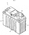
- FIG. 1 is a diagram for illustrating a battery pack according to an embodiment of the present disclosure
- FIG. 2 is a perspective view showing a case body of a pack case, employed at the battery pack of FIG. 1
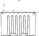
- FIG. 3 is a side view showing the case body of FIG. 2
- FIG. 4 is an enlarged view showing a portion A of the case body of FIG. 3 .
- a battery pack 10 may be provided as an energy source in an electric vehicle, a hybrid vehicle, or the like. However, the present disclosure is not limited thereto, and the battery pack 10 may also be provided as a domestic or industrial energy source.
- the battery pack 10 may include a battery module 100, a pack case 200, and a weldability checking guider 300.
- the battery module 100 may include at least one battery cell or a plurality of battery cells.
- the battery cell is a secondary battery and may be provided as a pouch-type secondary battery.
- the present disclosure is not limited thereto, and the battery cell may also be a cylindrical or rectangular secondary battery.
- the pack case 200 is for packaging the battery module 100 and may include a case body 210 and a case cover 230.
- the case body 210 may have an accommodation space for accommodating the battery module 100.
- the case body 210 may be welded to a case cover 230, explained later, to package the battery module 100.
- the welding may be performed at an upper side of the case body 210, specifically at an upper rim 215 of the case body 210. By means of the welding, the inside of the pack case 200 may be sealed.
- the case cover 230 covers the upper side of the case body 210 and may be connected to the case body 210 by means of the welding to package the battery module 100 together with the case body 210. Specifically, the case cover 230 may be welded to the upper rim 215 of the case body 210.
- the weldability checking guider 300 is to check the accuracy of the welding, such as the weldability of the welding, and may be provided at the case body 210 of the pack case 200. Specifically, the weldability checking guider 300 may be formed at the upper rim 215 of the case body 210.
- the weldability checking guider 300 may guide the accuracy of welding such as the weldability to be observed by the eyes of a user. Specifically, when the case body 210 and the case cover 230 are welded, a height and/or slope of the case cover 230 is changed as a weld portion of the case body 210 is melted down, and the weldability checking guider 300 may allow the changed height and/or slope of the case cover 230 to be observed by the eyes of the user.
- the weldability checking guider 300 may be provided in plural, and the plurality of weldability checking guiders 300 may be disposed to be spaced apart from each other by a predetermined distance along the upper rim 215 of the case body 210.
- the plurality of weldability checking guides 300 may include a plurality of dimension carved portions 310, 330, respectively.
- the plurality of dimensioned carved portions 310, 330 may have a predetermined length along a horizontal direction of the case body 210 and may be spaced apart from each other by a predetermined distance along a vertical direction of the case body 210.
- the plurality of dimensioned carved portions 310, 330 may be provided as dimension carved grooves formed with a predetermined depth from the case body 210.
- the present disclosure is not limited thereto, and it is also possible that the plurality of dimensioned carved portions 310, 330 have a protruding shape that may be easily observed by the eyes of the user.
- the plurality of carved portions 310, 330 may be formed at positions where the entire width W of the plurality of carved portions 310, 330 along the vertical direction of the case body 210 may serve as an indicator for assuring the accuracy of the welding during the welding process. Accordingly, if the bottom portion of the case cover 230 lowered by the welding is located inside the entire width of the plurality of dimension carved portions 310, 330 along the vertical direction during the welding process, the user may determine that the welding has been performed to guarantee the sealing force.
- the plurality of dimensioned carved portions 310, 330 may be formed to have at least two different lengths in the horizontal direction of the case body 210. Moreover, the dimension carved portions 310, 330 having different lengths may be alternately arranged in the vertical direction of the case body 210. This is to enable the visibility of the user to be further increased when the plurality of dimensioned carved portions 310, 330 are checked by the eyes of the user.
- FIG. 5 is a diagram for illustrating a welding work for the pack case, employed at the battery pack of FIG. 1
- FIGS. 6 to 8 are diagrams for illustrating a process of checking welding quality using a weldability checking guider during the welding work of FIG. 5 .
- the case body 210 and the case cover 230 of the pack case 200 are welded, at least one of height and slope of the case cover 230 may be changed to be lowered toward a lower side of the case body 210 as the welding is being performed.
- the user such as a worker may more conveniently check the changed position of the case cover 230 by means of the weldability checking guider 300.
- the accuracy of the weldability may be more conveniently checked by visual inspecting the changed position of the case cover 230 by means of the weldability checking guider 300.
- the user such as a worker may check that the welding is performed properly if the lowered height h of the case cover 230 is located within the entire width W (see FIG. 4 ) of the weldability checking guide 300 and the case cover 230 is parallel to the horizontal length of the dimensionally carved portions 310, 330 of the weldability checking guider 300.
- the welding is determined as bad in the following cases. As shown in FIG. 7 , if the lowered height h1 of the case cover 230 is located above the uppermost end of the dimension carved portions 310, 330 of the weldability checking guider 300, the user may check this by the eyes and determine that the welding is bad.
- the user may check this by the eyes and determine that the welding is bad.
- the accuracy of the welding of the pack case 200 may be checked only by the eyes of the user such as a worker by means of the weldability checking guider 300.
- the accuracy of the welding may be clearly determined by checking whether the lower end of the case cover 230 is located within the width range in the vertical direction of the weldability checking guider 300 and also by checking the slope of the lower end of the case cover 230 with respect to the weldability checking guider 300.
- the weldability of the pack case 200 is capable of being immediately checked by the eyes of the user such as a worker during the welding process by means of the weldability checking guider 300 provided at the case body 210 of the pack case 200, there is no need for a follow-up confirmation process using equipment such as a separate sensor for checking the weldability.
- the cost and additional overall process time caused by the addition of a separate welding checking facility may be significantly reduced.
- a battery pack 10 which may more easily check the weldability of the pack case 200 during a welding process, and a vehicle including the battery pack.
- a battery pack 10 which may quantitatively determine the weldability of the pack case 200 during a welding process, and a vehicle including the battery pack.
Landscapes
- Chemical & Material Sciences (AREA)
- Chemical Kinetics & Catalysis (AREA)
- Electrochemistry (AREA)
- General Chemical & Material Sciences (AREA)
- Engineering & Computer Science (AREA)
- Mechanical Engineering (AREA)
- Aviation & Aerospace Engineering (AREA)
- Manufacturing & Machinery (AREA)
- Quality & Reliability (AREA)
- Battery Mounting, Suspending (AREA)
- Sealing Battery Cases Or Jackets (AREA)
Abstract
Description
- The present disclosure relates to a battery pack, and a vehicle including the battery pack.
- The present application claims priority to Korean Patent Application No.
10-2017-0106049 filed on August 22, 2017 - Secondary batteries which are highly applicable to various products and exhibit superior electrical properties such as high energy density, etc. are commonly used not only in portable devices but also in electric vehicles (EVs) or hybrid electric vehicles (HEVs) driven by electrical power sources. The secondary battery is drawing attentions as a new energy source for enhancing environment friendliness and energy efficiency in that the use of fossil fuels can be reduced greatly and no byproduct is generated during energy consumption.
- Secondary batteries widely used at the preset include lithium ion batteries, lithium polymer batteries, nickel cadmium batteries, nickel hydrogen batteries, nickel zinc batteries and the like. An operating voltage of the unit secondary battery cell, namely a unit battery cell, is about 2.5 V to 4.6 V. Therefore, if a higher output voltage is required, a plurality of battery cells may be connected in series to configure a battery pack. In addition, depending on the charge/discharge capacity required for the battery pack, a plurality of battery cells may be connected in parallel to configure a battery pack. Thus, the number of battery cells included in the battery pack may be variously set according to the required output voltage or the demanded charge/discharge capacity.
- Meanwhile, when a plurality of battery cells are connected in series or in parallel to configure a battery pack, it is common to configure a battery module composed of at least one battery cell first, and then configure a battery pack by using at least one battery module and adding other components. Here, the battery cells configuring the battery module or the battery pack are generally pouch-type secondary batteries that may be easily stacked on one another.
- A conventional battery pack includes a battery module having at least one battery cell, and a pack case for packaging the battery module. The pack case includes a case body for accommodating the battery module, and a case cover welded to the case body to package the battery module.
- In the conventional battery pack, the weldability according to the welding work is related to the sealing force of the pack case, so checking the weldability between the case body and the case cover is an important factor in the welding process.
- In the conventional technique, the weldability is checked from the melting height of the welding surface between the case body and the case cover. The height may be checked using a separate sensor or other equipment.
- However, the process of checking weldability by using such a separate sensor or the like is performed as a separate process after the welding work, thereby increasing the cost due to the addition of the process equipment and extending the process time.
- Moreover, if the weldability is checked in the conventional battery pack, since entire the welding surface is not uniformly melted, it is difficult to determine an accurate dimension only by the qualitative judgment of a worker through the sensor or the like.
- Therefore, the present disclosure is directed to providing a battery pack, which may more easily check the weldability of a pack case during a welding process, and a vehicle including the battery pack.
- In addition, the present disclosure is also directed to providing a battery pack, which may quantitatively determine the weldability of a pack case during a welding process, and a vehicle including the battery pack.
- In one aspect of the present disclosure, there is provided a battery pack, comprising: a battery module having at least one battery cell; a pack case having a case body for accommodating the battery module and a case cover welded to the case body to package the battery module; and at least one weldability checking guider provided at the case body of the pack case to check accuracy of the welding.
- The case cover may be coupled to an upper rim of the case body by means of the welding, and the at least one weldability checking guider may be formed at the upper rim of the case body.
- At least one of height and slope of the case cover may be changed along a lower side of the case body by means of the welding, and the at least one weldability checking guider may guide the changed height and/or slope of the case cover to be observed by the eyes of a user.
- The at least one weldability checking guider may include a plurality of dimension carved portions formed with a predetermined length along a horizontal direction of the case body.
- The plurality of dimension carved portions may be disposed to be spaced apart from each other by a predetermined distance along a vertical direction of the case body.
- The plurality of dimension carved portions may be formed to have at least two different lengths.
- The dimension carved portions having different lengths may be arranged alternately.
- The plurality of dimension carved portions may be provided as dimension carved grooves formed with a predetermined depth at the case body.
- The weldability checking guider may be provided in plural, and the plurality of weldability checking guiders may be disposed to be spaced apart from each other by a predetermined distance along the upper rim of the case body.
- In another aspect of the present disclosure, there is also provided a vehicle, comprising at least one battery pack according to the above embodiments.
- According to various embodiments as above, it is possible to provide a battery pack, which may more easily check the weldability of a pack case during a welding process, and a vehicle including the battery pack.
- In addition, according to various embodiments as above, it is possible to provide a battery pack, which may quantitatively determine the weldability of a pack case during a welding process, and a vehicle including the battery pack.
- The accompanying drawings illustrate a preferred embodiment of the present disclosure and together with the foregoing disclosure, serve to provide further understanding of the technical features of the present disclosure, and thus, the present disclosure is not construed as being limited to the drawing.
-
FIG. 1 is a diagram for illustrating a battery pack according to an embodiment of the present disclosure. -
FIG. 2 is a perspective view showing a case body of a pack case, employed at the battery pack ofFIG. 1 . -
FIG. 3 is a side view showing the case body ofFIG. 2 . -
FIG. 4 is an enlarged view showing a portion A of the case body ofFIG. 3 . -
FIG. 5 is a diagram for illustrating a welding work for the pack case, employed at the battery pack ofFIG. 1 . -
FIGS. 6 to 8 are diagrams for illustrating a process of checking welding quality using a weldability checking guider during the welding work ofFIG. 5 . - The present disclosure will become more apparent by describing in detail the embodiments of the present disclosure with reference to the accompanying drawings. It should be understood that the embodiments disclosed herein are illustrative only for better understanding of the present disclosure, and that the present disclosure may be modified in various ways. In addition, for ease understanding of the present disclosure, the accompanying drawings are not drawn to real scale, but the dimensions of some components may be exaggerated.
-
FIG. 1 is a diagram for illustrating a battery pack according to an embodiment of the present disclosure,FIG. 2 is a perspective view showing a case body of a pack case, employed at the battery pack ofFIG. 1 ,FIG. 3 is a side view showing the case body ofFIG. 2 , andFIG. 4 is an enlarged view showing a portion A of the case body ofFIG. 3 . - Referring to
FIGS. 1 to 4 , abattery pack 10 may be provided as an energy source in an electric vehicle, a hybrid vehicle, or the like. However, the present disclosure is not limited thereto, and thebattery pack 10 may also be provided as a domestic or industrial energy source. - The
battery pack 10 may include abattery module 100, apack case 200, and aweldability checking guider 300. - The
battery module 100 may include at least one battery cell or a plurality of battery cells. The battery cell is a secondary battery and may be provided as a pouch-type secondary battery. However, the present disclosure is not limited thereto, and the battery cell may also be a cylindrical or rectangular secondary battery. - The
pack case 200 is for packaging thebattery module 100 and may include acase body 210 and acase cover 230. - The
case body 210 may have an accommodation space for accommodating thebattery module 100. Thecase body 210 may be welded to acase cover 230, explained later, to package thebattery module 100. - The welding may be performed at an upper side of the
case body 210, specifically at anupper rim 215 of thecase body 210. By means of the welding, the inside of thepack case 200 may be sealed. - The
case cover 230 covers the upper side of thecase body 210 and may be connected to thecase body 210 by means of the welding to package thebattery module 100 together with thecase body 210. Specifically, thecase cover 230 may be welded to theupper rim 215 of thecase body 210. - The
weldability checking guider 300 is to check the accuracy of the welding, such as the weldability of the welding, and may be provided at thecase body 210 of thepack case 200. Specifically, theweldability checking guider 300 may be formed at theupper rim 215 of thecase body 210. - The
weldability checking guider 300 may guide the accuracy of welding such as the weldability to be observed by the eyes of a user. Specifically, when thecase body 210 and thecase cover 230 are welded, a height and/or slope of thecase cover 230 is changed as a weld portion of thecase body 210 is melted down, and theweldability checking guider 300 may allow the changed height and/or slope of thecase cover 230 to be observed by the eyes of the user. - The
weldability checking guider 300 may be provided in plural, and the plurality ofweldability checking guiders 300 may be disposed to be spaced apart from each other by a predetermined distance along theupper rim 215 of thecase body 210. - The plurality of weldability checking guides 300 may include a plurality of dimension carved
portions - The plurality of dimensioned carved
portions case body 210 and may be spaced apart from each other by a predetermined distance along a vertical direction of thecase body 210. - The plurality of dimensioned carved
portions case body 210. However, the present disclosure is not limited thereto, and it is also possible that the plurality of dimensioned carvedportions - The plurality of carved
portions portions case body 210 may serve as an indicator for assuring the accuracy of the welding during the welding process. Accordingly, if the bottom portion of thecase cover 230 lowered by the welding is located inside the entire width of the plurality of dimension carvedportions - The plurality of dimensioned carved
portions case body 210. Moreover, the dimension carvedportions case body 210. This is to enable the visibility of the user to be further increased when the plurality of dimensioned carvedportions - Hereinafter, the weldability checking mechanism through the
weldability checking guider 300 having the plurality of dimensionally carvedportions -
FIG. 5 is a diagram for illustrating a welding work for the pack case, employed at the battery pack ofFIG. 1 , andFIGS. 6 to 8 are diagrams for illustrating a process of checking welding quality using a weldability checking guider during the welding work ofFIG. 5 . - Referring to
FIGS. 5 to 8 , in thebattery pack 10, when thecase body 210 and thecase cover 230 of thepack case 200 are welded, at least one of height and slope of thecase cover 230 may be changed to be lowered toward a lower side of thecase body 210 as the welding is being performed. - Here, the user such as a worker may more conveniently check the changed position of the
case cover 230 by means of theweldability checking guider 300. In this embodiment, the accuracy of the weldability may be more conveniently checked by visual inspecting the changed position of thecase cover 230 by means of theweldability checking guider 300. - For example, as shown in
FIG. 6 , the user such as a worker may check that the welding is performed properly if the lowered height h of thecase cover 230 is located within the entire width W (seeFIG. 4 ) of theweldability checking guide 300 and thecase cover 230 is parallel to the horizontal length of the dimensionally carvedportions weldability checking guider 300. - The welding is determined as bad in the following cases. As shown in
FIG. 7 , if the lowered height h1 of thecase cover 230 is located above the uppermost end of the dimension carvedportions weldability checking guider 300, the user may check this by the eyes and determine that the welding is bad. - In addition, as shown in
FIG. 8 , if thecase cover 230 is disposed to have a predetermined slope ( ) with respect to the dimensionally carvedportions weldability checking guider 300, the user may check this by the eyes and determine that the welding is bad. - As described above, in this embodiment, the accuracy of the welding of the
pack case 200 may be checked only by the eyes of the user such as a worker by means of theweldability checking guider 300. - Moreover, in this embodiment, the accuracy of the welding may be clearly determined by checking whether the lower end of the
case cover 230 is located within the width range in the vertical direction of theweldability checking guider 300 and also by checking the slope of the lower end of thecase cover 230 with respect to theweldability checking guider 300. Thus, it is also possible to quantitatively determine the accuracy of the welding by means of theweldability checking guider 300. - As described above, in this embodiment, since the weldability of the
pack case 200 is capable of being immediately checked by the eyes of the user such as a worker during the welding process by means of theweldability checking guider 300 provided at thecase body 210 of thepack case 200, there is no need for a follow-up confirmation process using equipment such as a separate sensor for checking the weldability. Thus, in this embodiment, the cost and additional overall process time caused by the addition of a separate welding checking facility may be significantly reduced. - According to various embodiments as above, it is possible to provide a
battery pack 10, which may more easily check the weldability of thepack case 200 during a welding process, and a vehicle including the battery pack. - In addition, according to various embodiments as above, it is possible to provide a
battery pack 10, which may quantitatively determine the weldability of thepack case 200 during a welding process, and a vehicle including the battery pack. - While the embodiments of the present disclosure have been shown and described, it should be understood that the present disclosure is not limited to the specific embodiments described, and that various changes and modifications can be made within the scope of the present disclosure by those skilled in the art, and these modifications should not be understood individually from the technical ideas and views of the present disclosure.
Claims (10)
- A battery pack, comprising:a battery module having at least one battery cell;a pack case having a case body for accommodating the battery module and a case cover welded to the case body to package the battery module; andat least one weldability checking guider provided at the case body of the pack case to check accuracy of the welding.
- The battery pack according to claim 1,
wherein the case cover is coupled to an upper rim of the case body by means of the welding, and
wherein the at least one weldability checking guider is formed at the upper rim of the case body. - The battery pack according to claim 2,
wherein at least one of height and slope of the case cover is changed along a lower side of the case body by means of the welding, and
wherein the at least one weldability checking guider guides the changed height and/or slope of the case cover to be observed by the eyes of a user. - The battery pack according to claim 2,
wherein the at least one weldability checking guider includes a plurality of dimension carved portions formed with a predetermined length along a horizontal direction of the case body. - The battery pack according to claim 4,
wherein the plurality of dimension carved portions are disposed to be spaced apart from each other by a predetermined distance along a vertical direction of the case body. - The battery pack according to claim 4,
wherein the plurality of dimension carved portions are formed to have at least two different lengths. - The battery pack according to claim 6,
wherein the dimension carved portions having different lengths are arranged alternately. - The battery pack according to claim 4,
wherein the plurality of dimension carved portions are provided as dimension carved grooves formed with a predetermined depth at the case body. - The battery pack according to claim 2,
wherein the weldability checking guider is provided in plural, and
wherein the plurality of weldability checking guiders are disposed to be spaced apart from each other by a predetermined distance along the upper rim of the case body. - A vehicle, comprising at least one battery pack according to claim 1.
Applications Claiming Priority (2)
| Application Number | Priority Date | Filing Date | Title |
|---|---|---|---|
| KR1020170106049A KR102175940B1 (en) | 2017-08-22 | 2017-08-22 | Battery pack and vehicle comprising the same |
| PCT/KR2018/008293 WO2019039744A1 (en) | 2017-08-22 | 2018-07-23 | Battery pack and automobile comprising same |
Publications (3)
| Publication Number | Publication Date |
|---|---|
| EP3573132A1 true EP3573132A1 (en) | 2019-11-27 |
| EP3573132A4 EP3573132A4 (en) | 2020-05-27 |
| EP3573132B1 EP3573132B1 (en) | 2023-06-21 |
Family
ID=65440100
Family Applications (1)
| Application Number | Title | Priority Date | Filing Date |
|---|---|---|---|
| EP18847458.9A Active EP3573132B1 (en) | 2017-08-22 | 2018-07-23 | Battery pack and automobile comprising same |
Country Status (9)
| Country | Link |
|---|---|
| US (1) | US11050104B2 (en) |
| EP (1) | EP3573132B1 (en) |
| JP (1) | JP7038948B2 (en) |
| KR (1) | KR102175940B1 (en) |
| CN (1) | CN110199408B (en) |
| ES (1) | ES2950683T3 (en) |
| HU (1) | HUE062444T2 (en) |
| PL (1) | PL3573132T3 (en) |
| WO (1) | WO2019039744A1 (en) |
Families Citing this family (7)
| Publication number | Priority date | Publication date | Assignee | Title |
|---|---|---|---|---|
| CN111496381B (en) * | 2020-04-29 | 2022-04-19 | 中国工程物理研究院核物理与化学研究所 | Device and method for assembling and packaging isotope battery |
| USD911933S1 (en) * | 2020-07-10 | 2021-03-02 | Inventus Power, Inc. | Battery |
| USD910546S1 (en) * | 2020-07-10 | 2021-02-16 | Inventus Power, Inc. | Battery |
| USD910547S1 (en) | 2020-07-21 | 2021-02-16 | Inventus Power, Inc. | Battery |
| USD971827S1 (en) | 2020-07-30 | 2022-12-06 | Dragonfly Energy Corp. | Battery pack |
| US12463268B2 (en) * | 2023-01-11 | 2025-11-04 | Ford Global Technologies, Llc | Volume filler for immersion cooling battery array designs |
| JP2024143487A (en) * | 2023-03-30 | 2024-10-11 | 株式会社Aescジャパン | Battery module, manufacturing method for battery module, and inspection method for laser welding |
Family Cites Families (23)
| Publication number | Priority date | Publication date | Assignee | Title |
|---|---|---|---|---|
| GB1569410A (en) * | 1975-12-20 | 1980-06-11 | Lucas Industries Ltd | Electric storage batteries |
| US4828943A (en) * | 1987-11-02 | 1989-05-09 | Southern Company Services, Inc. | Battery having indicia for correcting specific gravity determination at varying electrolyte levels |
| JP3008941U (en) | 1994-09-12 | 1995-03-28 | フジツール株式会社 | Welding gauge |
| US5605549A (en) * | 1996-02-28 | 1997-02-25 | Daramic, Inc. | Battery electrolyte pad with gelling agents and method |
| JP3973164B2 (en) * | 2003-11-21 | 2007-09-12 | 日立マクセル株式会社 | Sealed prismatic battery |
| JP4899313B2 (en) * | 2004-12-22 | 2012-03-21 | トヨタ自動車株式会社 | Battery, battery manufacturing method, and electrolyte leakage inspection method |
| JP4869592B2 (en) * | 2004-12-28 | 2012-02-08 | Necエナジーデバイス株式会社 | Sealed battery and method for manufacturing sealed battery |
| KR100786757B1 (en) | 2006-12-22 | 2007-12-18 | 한국생산기술연구원 | Welding quality coaxial monitoring device for laser welding using image sensor |
| JP2008186712A (en) * | 2007-01-30 | 2008-08-14 | Hitachi Maxell Ltd | Sealed battery |
| JP5200420B2 (en) * | 2007-05-16 | 2013-06-05 | ソニー株式会社 | Battery pack |
| JP5306746B2 (en) * | 2007-09-26 | 2013-10-02 | 日立マクセル株式会社 | Battery pack |
| KR100926550B1 (en) | 2007-11-30 | 2009-11-12 | 현대자동차주식회사 | Welding quality inspection system and its inspection method |
| US20110151297A1 (en) * | 2009-06-22 | 2011-06-23 | Keisuke Shimizu | Battery and battery pack |
| JP2011090861A (en) | 2009-10-22 | 2011-05-06 | Panasonic Corp | Lead-acid storage battery |
| JP5821605B2 (en) | 2011-12-16 | 2015-11-24 | 三菱自動車工業株式会社 | Secondary battery |
| KR101906923B1 (en) | 2012-06-14 | 2018-10-11 | 에스케이이노베이션 주식회사 | Battery Module and Laser welding method for Battery Module |
| KR101397029B1 (en) | 2012-09-13 | 2014-05-20 | 삼성에스디아이 주식회사 | Battery cell assembly, battery pack comprising the same, method for manufacturing the batter cell and zig assembly for manufacturing the batter cell assembly |
| KR101357223B1 (en) | 2013-04-19 | 2014-02-04 | 엠에스파이프 주식회사 | Apparatus for indicating the weld zones of a pipe |
| KR101738721B1 (en) | 2013-10-31 | 2017-05-22 | 주식회사 엘지화학 | Welding test apparatus |
| JP6512474B2 (en) * | 2015-04-21 | 2019-05-15 | パナソニックIpマネジメント株式会社 | Laser processing apparatus and laser welding quality determination method for battery |
| KR101944957B1 (en) * | 2015-07-20 | 2019-02-01 | 주식회사 엘지화학 | Battery pack and vehicle comprising the same |
| JP6613813B2 (en) * | 2015-10-29 | 2019-12-04 | 株式会社豊田自動織機 | Method for manufacturing electrode assembly and electrode assembly |
| KR20170106049A (en) | 2016-03-11 | 2017-09-20 | 주식회사 코리아나화장품 | Cosmetic composition comprising the extract of Morinda officinalis Haw. as active ingredient |
-
2017
- 2017-08-22 KR KR1020170106049A patent/KR102175940B1/en active Active
-
2018
- 2018-07-23 EP EP18847458.9A patent/EP3573132B1/en active Active
- 2018-07-23 HU HUE18847458A patent/HUE062444T2/en unknown
- 2018-07-23 US US16/481,266 patent/US11050104B2/en active Active
- 2018-07-23 JP JP2019538204A patent/JP7038948B2/en active Active
- 2018-07-23 PL PL18847458.9T patent/PL3573132T3/en unknown
- 2018-07-23 WO PCT/KR2018/008293 patent/WO2019039744A1/en not_active Ceased
- 2018-07-23 ES ES18847458T patent/ES2950683T3/en active Active
- 2018-07-23 CN CN201880007828.6A patent/CN110199408B/en active Active
Also Published As
| Publication number | Publication date |
|---|---|
| JP2020514984A (en) | 2020-05-21 |
| CN110199408B (en) | 2023-05-12 |
| US11050104B2 (en) | 2021-06-29 |
| HUE062444T2 (en) | 2023-11-28 |
| EP3573132A4 (en) | 2020-05-27 |
| PL3573132T3 (en) | 2023-09-04 |
| JP7038948B2 (en) | 2022-03-22 |
| WO2019039744A1 (en) | 2019-02-28 |
| KR102175940B1 (en) | 2020-11-06 |
| ES2950683T3 (en) | 2023-10-11 |
| EP3573132B1 (en) | 2023-06-21 |
| CN110199408A (en) | 2019-09-03 |
| KR20190021008A (en) | 2019-03-05 |
| US20200044204A1 (en) | 2020-02-06 |
Similar Documents
| Publication | Publication Date | Title |
|---|---|---|
| EP3573132B1 (en) | Battery pack and automobile comprising same | |
| EP3836244B1 (en) | Battery module and battery pack comprising battery module | |
| EP3305460B1 (en) | Battery module, method of welding electrode leads of battery cells, and battery pack comprising the battery module | |
| EP3561902B1 (en) | Battery module, battery pack comprising battery module, and vehicle comprising battery pack | |
| EP3670154B1 (en) | Apparatus for sealing pouch case | |
| EP3799155B1 (en) | Battery module, battery pack comprising battery module, and vehicle comprising battery pack | |
| EP3336928A1 (en) | Battery module, battery pack including battery module, and vehicle including battery pack | |
| EP3731302A1 (en) | Battery module, battery pack comprising same battery module, and vehicle comprising same battery pack | |
| JP6578438B2 (en) | Battery module, battery pack including the battery module, and automobile including the battery pack | |
| EP3675208B1 (en) | Battery module and battery pack including same | |
| JP2022540670A (en) | Battery modules, battery packs containing same and motor vehicles containing such battery packs | |
| KR20200104614A (en) | Battery pack having bending shaped sensing bus bar and device including the same | |
| EP4576353A1 (en) | Battery cell and, battery module including same, and battery pack including same, and vehicle including same | |
| KR20170043306A (en) | Battery module, battery pack comprising the battery module and vehicle comprising the battery pack |
Legal Events
| Date | Code | Title | Description |
|---|---|---|---|
| STAA | Information on the status of an ep patent application or granted ep patent |
Free format text: STATUS: THE INTERNATIONAL PUBLICATION HAS BEEN MADE |
|
| PUAI | Public reference made under article 153(3) epc to a published international application that has entered the european phase |
Free format text: ORIGINAL CODE: 0009012 |
|
| STAA | Information on the status of an ep patent application or granted ep patent |
Free format text: STATUS: REQUEST FOR EXAMINATION WAS MADE |
|
| 17P | Request for examination filed |
Effective date: 20190821 |
|
| AK | Designated contracting states |
Kind code of ref document: A1 Designated state(s): AL AT BE BG CH CY CZ DE DK EE ES FI FR GB GR HR HU IE IS IT LI LT LU LV MC MK MT NL NO PL PT RO RS SE SI SK SM TR |
|
| AX | Request for extension of the european patent |
Extension state: BA ME |
|
| A4 | Supplementary search report drawn up and despatched |
Effective date: 20200428 |
|
| RIC1 | Information provided on ipc code assigned before grant |
Ipc: H01M 10/04 20060101ALN20200421BHEP Ipc: B23K 31/12 20060101ALI20200421BHEP Ipc: H01M 2/04 20060101ALI20200421BHEP Ipc: H01M 2/10 20060101AFI20200421BHEP Ipc: H01M 2/02 20060101ALI20200421BHEP Ipc: B23K 101/36 20060101ALI20200421BHEP Ipc: H01M 10/48 20060101ALN20200421BHEP |
|
| DAV | Request for validation of the european patent (deleted) | ||
| DAX | Request for extension of the european patent (deleted) | ||
| RAP1 | Party data changed (applicant data changed or rights of an application transferred) |
Owner name: LG ENERGY SOLUTION LTD. |
|
| RAP3 | Party data changed (applicant data changed or rights of an application transferred) |
Owner name: LG ENERGY SOLUTION, LTD. |
|
| REG | Reference to a national code |
Ref country code: DE Ref legal event code: R079 Free format text: PREVIOUS MAIN CLASS: H01M0002100000 Ipc: B23K0031120000 Ref country code: DE Ref legal event code: R079 Ref document number: 602018052213 Country of ref document: DE Free format text: PREVIOUS MAIN CLASS: H01M0002100000 Ipc: B23K0031120000 |
|
| GRAP | Despatch of communication of intention to grant a patent |
Free format text: ORIGINAL CODE: EPIDOSNIGR1 |
|
| STAA | Information on the status of an ep patent application or granted ep patent |
Free format text: STATUS: GRANT OF PATENT IS INTENDED |
|
| RIC1 | Information provided on ipc code assigned before grant |
Ipc: H01M 10/48 20060101ALN20230228BHEP Ipc: H01M 10/04 20060101ALN20230228BHEP Ipc: H01M 50/249 20210101ALI20230228BHEP Ipc: H01M 50/202 20210101ALI20230228BHEP Ipc: H01M 50/169 20210101ALI20230228BHEP Ipc: H01M 50/103 20210101ALI20230228BHEP Ipc: B23K 31/12 20060101AFI20230228BHEP |
|
| INTG | Intention to grant announced |
Effective date: 20230328 |
|
| GRAS | Grant fee paid |
Free format text: ORIGINAL CODE: EPIDOSNIGR3 |
|
| GRAA | (expected) grant |
Free format text: ORIGINAL CODE: 0009210 |
|
| STAA | Information on the status of an ep patent application or granted ep patent |
Free format text: STATUS: THE PATENT HAS BEEN GRANTED |
|
| AK | Designated contracting states |
Kind code of ref document: B1 Designated state(s): AL AT BE BG CH CY CZ DE DK EE ES FI FR GB GR HR HU IE IS IT LI LT LU LV MC MK MT NL NO PL PT RO RS SE SI SK SM TR |
|
| P01 | Opt-out of the competence of the unified patent court (upc) registered |
Effective date: 20230516 |
|
| REG | Reference to a national code |
Ref country code: CH Ref legal event code: EP |
|
| REG | Reference to a national code |
Ref country code: DE Ref legal event code: R096 Ref document number: 602018052213 Country of ref document: DE |
|
| REG | Reference to a national code |
Ref country code: AT Ref legal event code: REF Ref document number: 1580560 Country of ref document: AT Kind code of ref document: T Effective date: 20230715 |
|
| REG | Reference to a national code |
Ref country code: IE Ref legal event code: FG4D |
|
| REG | Reference to a national code |
Ref country code: SE Ref legal event code: TRGR |
|
| REG | Reference to a national code |
Ref country code: LT Ref legal event code: MG9D |
|
| REG | Reference to a national code |
Ref country code: ES Ref legal event code: FG2A Ref document number: 2950683 Country of ref document: ES Kind code of ref document: T3 Effective date: 20231011 |
|
| REG | Reference to a national code |
Ref country code: NL Ref legal event code: MP Effective date: 20230621 |
|
| PG25 | Lapsed in a contracting state [announced via postgrant information from national office to epo] |
Ref country code: NO Free format text: LAPSE BECAUSE OF FAILURE TO SUBMIT A TRANSLATION OF THE DESCRIPTION OR TO PAY THE FEE WITHIN THE PRESCRIBED TIME-LIMIT Effective date: 20230921 |
|
| REG | Reference to a national code |
Ref country code: AT Ref legal event code: MK05 Ref document number: 1580560 Country of ref document: AT Kind code of ref document: T Effective date: 20230621 |
|
| REG | Reference to a national code |
Ref country code: HU Ref legal event code: AG4A Ref document number: E062444 Country of ref document: HU |
|
| PG25 | Lapsed in a contracting state [announced via postgrant information from national office to epo] |
Ref country code: RS Free format text: LAPSE BECAUSE OF FAILURE TO SUBMIT A TRANSLATION OF THE DESCRIPTION OR TO PAY THE FEE WITHIN THE PRESCRIBED TIME-LIMIT Effective date: 20230621 Ref country code: NL Free format text: LAPSE BECAUSE OF FAILURE TO SUBMIT A TRANSLATION OF THE DESCRIPTION OR TO PAY THE FEE WITHIN THE PRESCRIBED TIME-LIMIT Effective date: 20230621 Ref country code: LV Free format text: LAPSE BECAUSE OF FAILURE TO SUBMIT A TRANSLATION OF THE DESCRIPTION OR TO PAY THE FEE WITHIN THE PRESCRIBED TIME-LIMIT Effective date: 20230621 Ref country code: LT Free format text: LAPSE BECAUSE OF FAILURE TO SUBMIT A TRANSLATION OF THE DESCRIPTION OR TO PAY THE FEE WITHIN THE PRESCRIBED TIME-LIMIT Effective date: 20230621 Ref country code: HR Free format text: LAPSE BECAUSE OF FAILURE TO SUBMIT A TRANSLATION OF THE DESCRIPTION OR TO PAY THE FEE WITHIN THE PRESCRIBED TIME-LIMIT Effective date: 20230621 Ref country code: GR Free format text: LAPSE BECAUSE OF FAILURE TO SUBMIT A TRANSLATION OF THE DESCRIPTION OR TO PAY THE FEE WITHIN THE PRESCRIBED TIME-LIMIT Effective date: 20230922 |
|
| PG25 | Lapsed in a contracting state [announced via postgrant information from national office to epo] |
Ref country code: FI Free format text: LAPSE BECAUSE OF FAILURE TO SUBMIT A TRANSLATION OF THE DESCRIPTION OR TO PAY THE FEE WITHIN THE PRESCRIBED TIME-LIMIT Effective date: 20230621 |
|
| PG25 | Lapsed in a contracting state [announced via postgrant information from national office to epo] |
Ref country code: SK Free format text: LAPSE BECAUSE OF FAILURE TO SUBMIT A TRANSLATION OF THE DESCRIPTION OR TO PAY THE FEE WITHIN THE PRESCRIBED TIME-LIMIT Effective date: 20230621 |
|
| PG25 | Lapsed in a contracting state [announced via postgrant information from national office to epo] |
Ref country code: IS Free format text: LAPSE BECAUSE OF FAILURE TO SUBMIT A TRANSLATION OF THE DESCRIPTION OR TO PAY THE FEE WITHIN THE PRESCRIBED TIME-LIMIT Effective date: 20231021 |
|
| PG25 | Lapsed in a contracting state [announced via postgrant information from national office to epo] |
Ref country code: SM Free format text: LAPSE BECAUSE OF FAILURE TO SUBMIT A TRANSLATION OF THE DESCRIPTION OR TO PAY THE FEE WITHIN THE PRESCRIBED TIME-LIMIT Effective date: 20230621 Ref country code: SK Free format text: LAPSE BECAUSE OF FAILURE TO SUBMIT A TRANSLATION OF THE DESCRIPTION OR TO PAY THE FEE WITHIN THE PRESCRIBED TIME-LIMIT Effective date: 20230621 Ref country code: RO Free format text: LAPSE BECAUSE OF FAILURE TO SUBMIT A TRANSLATION OF THE DESCRIPTION OR TO PAY THE FEE WITHIN THE PRESCRIBED TIME-LIMIT Effective date: 20230621 Ref country code: PT Free format text: LAPSE BECAUSE OF FAILURE TO SUBMIT A TRANSLATION OF THE DESCRIPTION OR TO PAY THE FEE WITHIN THE PRESCRIBED TIME-LIMIT Effective date: 20231023 Ref country code: IS Free format text: LAPSE BECAUSE OF FAILURE TO SUBMIT A TRANSLATION OF THE DESCRIPTION OR TO PAY THE FEE WITHIN THE PRESCRIBED TIME-LIMIT Effective date: 20231021 Ref country code: EE Free format text: LAPSE BECAUSE OF FAILURE TO SUBMIT A TRANSLATION OF THE DESCRIPTION OR TO PAY THE FEE WITHIN THE PRESCRIBED TIME-LIMIT Effective date: 20230621 Ref country code: CZ Free format text: LAPSE BECAUSE OF FAILURE TO SUBMIT A TRANSLATION OF THE DESCRIPTION OR TO PAY THE FEE WITHIN THE PRESCRIBED TIME-LIMIT Effective date: 20230621 Ref country code: AT Free format text: LAPSE BECAUSE OF FAILURE TO SUBMIT A TRANSLATION OF THE DESCRIPTION OR TO PAY THE FEE WITHIN THE PRESCRIBED TIME-LIMIT Effective date: 20230621 |
|
| REG | Reference to a national code |
Ref country code: CH Ref legal event code: PL |
|
| PG25 | Lapsed in a contracting state [announced via postgrant information from national office to epo] |
Ref country code: MC Free format text: LAPSE BECAUSE OF FAILURE TO SUBMIT A TRANSLATION OF THE DESCRIPTION OR TO PAY THE FEE WITHIN THE PRESCRIBED TIME-LIMIT Effective date: 20230621 |
|
| REG | Reference to a national code |
Ref country code: BE Ref legal event code: MM Effective date: 20230731 |
|
| PG25 | Lapsed in a contracting state [announced via postgrant information from national office to epo] |
Ref country code: LU Free format text: LAPSE BECAUSE OF NON-PAYMENT OF DUE FEES Effective date: 20230723 |
|
| REG | Reference to a national code |
Ref country code: DE Ref legal event code: R097 Ref document number: 602018052213 Country of ref document: DE |
|
| PG25 | Lapsed in a contracting state [announced via postgrant information from national office to epo] |
Ref country code: MC Free format text: LAPSE BECAUSE OF FAILURE TO SUBMIT A TRANSLATION OF THE DESCRIPTION OR TO PAY THE FEE WITHIN THE PRESCRIBED TIME-LIMIT Effective date: 20230621 Ref country code: LU Free format text: LAPSE BECAUSE OF NON-PAYMENT OF DUE FEES Effective date: 20230723 |
|
| REG | Reference to a national code |
Ref country code: IE Ref legal event code: MM4A |
|
| PLBE | No opposition filed within time limit |
Free format text: ORIGINAL CODE: 0009261 |
|
| STAA | Information on the status of an ep patent application or granted ep patent |
Free format text: STATUS: NO OPPOSITION FILED WITHIN TIME LIMIT |
|
| PG25 | Lapsed in a contracting state [announced via postgrant information from national office to epo] |
Ref country code: DK Free format text: LAPSE BECAUSE OF FAILURE TO SUBMIT A TRANSLATION OF THE DESCRIPTION OR TO PAY THE FEE WITHIN THE PRESCRIBED TIME-LIMIT Effective date: 20230621 Ref country code: CH Free format text: LAPSE BECAUSE OF NON-PAYMENT OF DUE FEES Effective date: 20230731 |
|
| PG25 | Lapsed in a contracting state [announced via postgrant information from national office to epo] |
Ref country code: SI Free format text: LAPSE BECAUSE OF FAILURE TO SUBMIT A TRANSLATION OF THE DESCRIPTION OR TO PAY THE FEE WITHIN THE PRESCRIBED TIME-LIMIT Effective date: 20230621 |
|
| 26N | No opposition filed |
Effective date: 20240322 |
|
| PG25 | Lapsed in a contracting state [announced via postgrant information from national office to epo] |
Ref country code: SI Free format text: LAPSE BECAUSE OF FAILURE TO SUBMIT A TRANSLATION OF THE DESCRIPTION OR TO PAY THE FEE WITHIN THE PRESCRIBED TIME-LIMIT Effective date: 20230621 Ref country code: IT Free format text: LAPSE BECAUSE OF FAILURE TO SUBMIT A TRANSLATION OF THE DESCRIPTION OR TO PAY THE FEE WITHIN THE PRESCRIBED TIME-LIMIT Effective date: 20230621 Ref country code: BE Free format text: LAPSE BECAUSE OF NON-PAYMENT OF DUE FEES Effective date: 20230731 |
|
| PG25 | Lapsed in a contracting state [announced via postgrant information from national office to epo] |
Ref country code: IE Free format text: LAPSE BECAUSE OF NON-PAYMENT OF DUE FEES Effective date: 20230723 |
|
| PG25 | Lapsed in a contracting state [announced via postgrant information from national office to epo] |
Ref country code: IE Free format text: LAPSE BECAUSE OF NON-PAYMENT OF DUE FEES Effective date: 20230723 |
|
| PG25 | Lapsed in a contracting state [announced via postgrant information from national office to epo] |
Ref country code: BG Free format text: LAPSE BECAUSE OF FAILURE TO SUBMIT A TRANSLATION OF THE DESCRIPTION OR TO PAY THE FEE WITHIN THE PRESCRIBED TIME-LIMIT Effective date: 20230621 |
|
| PG25 | Lapsed in a contracting state [announced via postgrant information from national office to epo] |
Ref country code: BG Free format text: LAPSE BECAUSE OF FAILURE TO SUBMIT A TRANSLATION OF THE DESCRIPTION OR TO PAY THE FEE WITHIN THE PRESCRIBED TIME-LIMIT Effective date: 20230621 |
|
| PGFP | Annual fee paid to national office [announced via postgrant information from national office to epo] |
Ref country code: PL Payment date: 20250624 Year of fee payment: 8 |
|
| PGFP | Annual fee paid to national office [announced via postgrant information from national office to epo] |
Ref country code: GB Payment date: 20250624 Year of fee payment: 8 |
|
| PGFP | Annual fee paid to national office [announced via postgrant information from national office to epo] |
Ref country code: FR Payment date: 20250624 Year of fee payment: 8 |
|
| PG25 | Lapsed in a contracting state [announced via postgrant information from national office to epo] |
Ref country code: CY Free format text: LAPSE BECAUSE OF FAILURE TO SUBMIT A TRANSLATION OF THE DESCRIPTION OR TO PAY THE FEE WITHIN THE PRESCRIBED TIME-LIMIT; INVALID AB INITIO Effective date: 20180723 |
|
| PGFP | Annual fee paid to national office [announced via postgrant information from national office to epo] |
Ref country code: SE Payment date: 20250624 Year of fee payment: 8 |
|
| PGFP | Annual fee paid to national office [announced via postgrant information from national office to epo] |
Ref country code: HU Payment date: 20250721 Year of fee payment: 8 |
|
| PGFP | Annual fee paid to national office [announced via postgrant information from national office to epo] |
Ref country code: ES Payment date: 20250822 Year of fee payment: 8 |
|
| PGFP | Annual fee paid to national office [announced via postgrant information from national office to epo] |
Ref country code: DE Payment date: 20250624 Year of fee payment: 8 |
|
| PG25 | Lapsed in a contracting state [announced via postgrant information from national office to epo] |
Ref country code: TR Free format text: LAPSE BECAUSE OF FAILURE TO SUBMIT A TRANSLATION OF THE DESCRIPTION OR TO PAY THE FEE WITHIN THE PRESCRIBED TIME-LIMIT Effective date: 20230621 |