EP3572839A1 - Method of estimating a velocity magnitude of a moving target in a horizontal plane and radar detection system - Google Patents
Method of estimating a velocity magnitude of a moving target in a horizontal plane and radar detection system Download PDFInfo
- Publication number
- EP3572839A1 EP3572839A1 EP18173846.9A EP18173846A EP3572839A1 EP 3572839 A1 EP3572839 A1 EP 3572839A1 EP 18173846 A EP18173846 A EP 18173846A EP 3572839 A1 EP3572839 A1 EP 3572839A1
- Authority
- EP
- European Patent Office
- Prior art keywords
- reflection
- velocity
- points
- estimated
- radar
- Prior art date
- Legal status (The legal status is an assumption and is not a legal conclusion. Google has not performed a legal analysis and makes no representation as to the accuracy of the status listed.)
- Withdrawn
Links
Images


Classifications
-
- G—PHYSICS
- G01—MEASURING; TESTING
- G01S—RADIO DIRECTION-FINDING; RADIO NAVIGATION; DETERMINING DISTANCE OR VELOCITY BY USE OF RADIO WAVES; LOCATING OR PRESENCE-DETECTING BY USE OF THE REFLECTION OR RERADIATION OF RADIO WAVES; ANALOGOUS ARRANGEMENTS USING OTHER WAVES
- G01S13/00—Systems using the reflection or reradiation of radio waves, e.g. radar systems; Analogous systems using reflection or reradiation of waves whose nature or wavelength is irrelevant or unspecified
- G01S13/02—Systems using reflection of radio waves, e.g. primary radar systems; Analogous systems
- G01S13/50—Systems of measurement based on relative movement of target
- G01S13/58—Velocity or trajectory determination systems; Sense-of-movement determination systems
- G01S13/588—Velocity or trajectory determination systems; Sense-of-movement determination systems deriving the velocity value from the range measurement
-
- G—PHYSICS
- G01—MEASURING; TESTING
- G01S—RADIO DIRECTION-FINDING; RADIO NAVIGATION; DETERMINING DISTANCE OR VELOCITY BY USE OF RADIO WAVES; LOCATING OR PRESENCE-DETECTING BY USE OF THE REFLECTION OR RERADIATION OF RADIO WAVES; ANALOGOUS ARRANGEMENTS USING OTHER WAVES
- G01S13/00—Systems using the reflection or reradiation of radio waves, e.g. radar systems; Analogous systems using reflection or reradiation of waves whose nature or wavelength is irrelevant or unspecified
- G01S13/88—Radar or analogous systems specially adapted for specific applications
- G01S13/93—Radar or analogous systems specially adapted for specific applications for anti-collision purposes
- G01S13/931—Radar or analogous systems specially adapted for specific applications for anti-collision purposes of land vehicles
-
- G—PHYSICS
- G01—MEASURING; TESTING
- G01S—RADIO DIRECTION-FINDING; RADIO NAVIGATION; DETERMINING DISTANCE OR VELOCITY BY USE OF RADIO WAVES; LOCATING OR PRESENCE-DETECTING BY USE OF THE REFLECTION OR RERADIATION OF RADIO WAVES; ANALOGOUS ARRANGEMENTS USING OTHER WAVES
- G01S13/00—Systems using the reflection or reradiation of radio waves, e.g. radar systems; Analogous systems using reflection or reradiation of waves whose nature or wavelength is irrelevant or unspecified
- G01S13/02—Systems using reflection of radio waves, e.g. primary radar systems; Analogous systems
- G01S13/06—Systems determining position data of a target
- G01S13/42—Simultaneous measurement of distance and other co-ordinates
-
- G—PHYSICS
- G01—MEASURING; TESTING
- G01S—RADIO DIRECTION-FINDING; RADIO NAVIGATION; DETERMINING DISTANCE OR VELOCITY BY USE OF RADIO WAVES; LOCATING OR PRESENCE-DETECTING BY USE OF THE REFLECTION OR RERADIATION OF RADIO WAVES; ANALOGOUS ARRANGEMENTS USING OTHER WAVES
- G01S13/00—Systems using the reflection or reradiation of radio waves, e.g. radar systems; Analogous systems using reflection or reradiation of waves whose nature or wavelength is irrelevant or unspecified
- G01S13/02—Systems using reflection of radio waves, e.g. primary radar systems; Analogous systems
- G01S13/50—Systems of measurement based on relative movement of target
- G01S13/58—Velocity or trajectory determination systems; Sense-of-movement determination systems
- G01S13/583—Velocity or trajectory determination systems; Sense-of-movement determination systems using transmission of continuous unmodulated waves, amplitude-, frequency-, or phase-modulated waves and based upon the Doppler effect resulting from movement of targets
- G01S13/584—Velocity or trajectory determination systems; Sense-of-movement determination systems using transmission of continuous unmodulated waves, amplitude-, frequency-, or phase-modulated waves and based upon the Doppler effect resulting from movement of targets adapted for simultaneous range and velocity measurements
-
- G—PHYSICS
- G01—MEASURING; TESTING
- G01S—RADIO DIRECTION-FINDING; RADIO NAVIGATION; DETERMINING DISTANCE OR VELOCITY BY USE OF RADIO WAVES; LOCATING OR PRESENCE-DETECTING BY USE OF THE REFLECTION OR RERADIATION OF RADIO WAVES; ANALOGOUS ARRANGEMENTS USING OTHER WAVES
- G01S13/00—Systems using the reflection or reradiation of radio waves, e.g. radar systems; Analogous systems using reflection or reradiation of waves whose nature or wavelength is irrelevant or unspecified
- G01S13/88—Radar or analogous systems specially adapted for specific applications
- G01S13/91—Radar or analogous systems specially adapted for specific applications for traffic control
- G01S13/92—Radar or analogous systems specially adapted for specific applications for traffic control for velocity measurement
-
- G—PHYSICS
- G01—MEASURING; TESTING
- G01S—RADIO DIRECTION-FINDING; RADIO NAVIGATION; DETERMINING DISTANCE OR VELOCITY BY USE OF RADIO WAVES; LOCATING OR PRESENCE-DETECTING BY USE OF THE REFLECTION OR RERADIATION OF RADIO WAVES; ANALOGOUS ARRANGEMENTS USING OTHER WAVES
- G01S7/00—Details of systems according to groups G01S13/00, G01S15/00, G01S17/00
- G01S7/02—Details of systems according to groups G01S13/00, G01S15/00, G01S17/00 of systems according to group G01S13/00
-
- G—PHYSICS
- G01—MEASURING; TESTING
- G01S—RADIO DIRECTION-FINDING; RADIO NAVIGATION; DETERMINING DISTANCE OR VELOCITY BY USE OF RADIO WAVES; LOCATING OR PRESENCE-DETECTING BY USE OF THE REFLECTION OR RERADIATION OF RADIO WAVES; ANALOGOUS ARRANGEMENTS USING OTHER WAVES
- G01S7/00—Details of systems according to groups G01S13/00, G01S15/00, G01S17/00
- G01S7/02—Details of systems according to groups G01S13/00, G01S15/00, G01S17/00 of systems according to group G01S13/00
- G01S7/28—Details of pulse systems
- G01S7/285—Receivers
- G01S7/292—Extracting wanted echo-signals
- G01S7/2921—Extracting wanted echo-signals based on data belonging to one radar period
-
- G—PHYSICS
- G01—MEASURING; TESTING
- G01S—RADIO DIRECTION-FINDING; RADIO NAVIGATION; DETERMINING DISTANCE OR VELOCITY BY USE OF RADIO WAVES; LOCATING OR PRESENCE-DETECTING BY USE OF THE REFLECTION OR RERADIATION OF RADIO WAVES; ANALOGOUS ARRANGEMENTS USING OTHER WAVES
- G01S13/00—Systems using the reflection or reradiation of radio waves, e.g. radar systems; Analogous systems using reflection or reradiation of waves whose nature or wavelength is irrelevant or unspecified
- G01S13/02—Systems using reflection of radio waves, e.g. primary radar systems; Analogous systems
- G01S13/06—Systems determining position data of a target
- G01S13/08—Systems for measuring distance only
- G01S13/32—Systems for measuring distance only using transmission of continuous waves, whether amplitude-, frequency-, or phase-modulated, or unmodulated
- G01S13/34—Systems for measuring distance only using transmission of continuous waves, whether amplitude-, frequency-, or phase-modulated, or unmodulated using transmission of continuous, frequency-modulated waves while heterodyning the received signal, or a signal derived therefrom, with a locally-generated signal related to the contemporaneously transmitted signal
- G01S13/343—Systems for measuring distance only using transmission of continuous waves, whether amplitude-, frequency-, or phase-modulated, or unmodulated using transmission of continuous, frequency-modulated waves while heterodyning the received signal, or a signal derived therefrom, with a locally-generated signal related to the contemporaneously transmitted signal using sawtooth modulation
-
- G—PHYSICS
- G01—MEASURING; TESTING
- G01S—RADIO DIRECTION-FINDING; RADIO NAVIGATION; DETERMINING DISTANCE OR VELOCITY BY USE OF RADIO WAVES; LOCATING OR PRESENCE-DETECTING BY USE OF THE REFLECTION OR RERADIATION OF RADIO WAVES; ANALOGOUS ARRANGEMENTS USING OTHER WAVES
- G01S13/00—Systems using the reflection or reradiation of radio waves, e.g. radar systems; Analogous systems using reflection or reradiation of waves whose nature or wavelength is irrelevant or unspecified
- G01S13/02—Systems using reflection of radio waves, e.g. primary radar systems; Analogous systems
- G01S13/50—Systems of measurement based on relative movement of target
- G01S13/58—Velocity or trajectory determination systems; Sense-of-movement determination systems
- G01S13/589—Velocity or trajectory determination systems; Sense-of-movement determination systems measuring the velocity vector
-
- G—PHYSICS
- G01—MEASURING; TESTING
- G01S—RADIO DIRECTION-FINDING; RADIO NAVIGATION; DETERMINING DISTANCE OR VELOCITY BY USE OF RADIO WAVES; LOCATING OR PRESENCE-DETECTING BY USE OF THE REFLECTION OR RERADIATION OF RADIO WAVES; ANALOGOUS ARRANGEMENTS USING OTHER WAVES
- G01S13/00—Systems using the reflection or reradiation of radio waves, e.g. radar systems; Analogous systems using reflection or reradiation of waves whose nature or wavelength is irrelevant or unspecified
- G01S13/87—Combinations of radar systems, e.g. primary radar and secondary radar
- G01S13/874—Combination of several systems for attitude determination
-
- G—PHYSICS
- G01—MEASURING; TESTING
- G01S—RADIO DIRECTION-FINDING; RADIO NAVIGATION; DETERMINING DISTANCE OR VELOCITY BY USE OF RADIO WAVES; LOCATING OR PRESENCE-DETECTING BY USE OF THE REFLECTION OR RERADIATION OF RADIO WAVES; ANALOGOUS ARRANGEMENTS USING OTHER WAVES
- G01S13/00—Systems using the reflection or reradiation of radio waves, e.g. radar systems; Analogous systems using reflection or reradiation of waves whose nature or wavelength is irrelevant or unspecified
- G01S13/88—Radar or analogous systems specially adapted for specific applications
- G01S13/93—Radar or analogous systems specially adapted for specific applications for anti-collision purposes
- G01S13/931—Radar or analogous systems specially adapted for specific applications for anti-collision purposes of land vehicles
- G01S2013/932—Radar or analogous systems specially adapted for specific applications for anti-collision purposes of land vehicles using own vehicle data, e.g. ground speed, steering wheel direction
-
- G—PHYSICS
- G01—MEASURING; TESTING
- G01S—RADIO DIRECTION-FINDING; RADIO NAVIGATION; DETERMINING DISTANCE OR VELOCITY BY USE OF RADIO WAVES; LOCATING OR PRESENCE-DETECTING BY USE OF THE REFLECTION OR RERADIATION OF RADIO WAVES; ANALOGOUS ARRANGEMENTS USING OTHER WAVES
- G01S13/00—Systems using the reflection or reradiation of radio waves, e.g. radar systems; Analogous systems using reflection or reradiation of waves whose nature or wavelength is irrelevant or unspecified
- G01S13/88—Radar or analogous systems specially adapted for specific applications
- G01S13/93—Radar or analogous systems specially adapted for specific applications for anti-collision purposes
- G01S13/931—Radar or analogous systems specially adapted for specific applications for anti-collision purposes of land vehicles
- G01S2013/9327—Sensor installation details
- G01S2013/93271—Sensor installation details in the front of the vehicles
-
- G—PHYSICS
- G01—MEASURING; TESTING
- G01S—RADIO DIRECTION-FINDING; RADIO NAVIGATION; DETERMINING DISTANCE OR VELOCITY BY USE OF RADIO WAVES; LOCATING OR PRESENCE-DETECTING BY USE OF THE REFLECTION OR RERADIATION OF RADIO WAVES; ANALOGOUS ARRANGEMENTS USING OTHER WAVES
- G01S13/00—Systems using the reflection or reradiation of radio waves, e.g. radar systems; Analogous systems using reflection or reradiation of waves whose nature or wavelength is irrelevant or unspecified
- G01S13/88—Radar or analogous systems specially adapted for specific applications
- G01S13/93—Radar or analogous systems specially adapted for specific applications for anti-collision purposes
- G01S13/931—Radar or analogous systems specially adapted for specific applications for anti-collision purposes of land vehicles
- G01S2013/9327—Sensor installation details
- G01S2013/93274—Sensor installation details on the side of the vehicles
Definitions
- the present invention relates to a method of estimating a velocity magnitude of a moving target in a horizontal plane using radar signals received by a radar detection system, the radar detection system being configured to resolve multiple dominant points of reflection, i.e. to receive a plurality of radar signals from the moving target in a single measurement instance of a single, wherein each of the resolved points of reflection is described by data relating to a range, an azimuth angle and a raw range rate of the points of reflection in said single radar measurement instance.
- the invention further relates to a radar detection system.
- Vehicles can be equipped with radars systems used to classify the environment in the vicinity of the vehicle such as to, e.g., detect moving or static objects around the vehicle.
- radars systems used to classify the environment in the vicinity of the vehicle such as to, e.g., detect moving or static objects around the vehicle.
- Such systems are, for example, used to estimate the motion state of other vehicles for automotive perception systems and can be used in active safety, driver assistance and autonomous driving applications. Due to the perceptive capabilities of the system, in particular to sense other vehicle, vehicles which are equipped with the system are usually denoted as host vehicles.
- a radar system typically includes Doppler radar technology implemented in a radar sensor unit adapted to receive signals emitted from a host vehicle and reflected by a target.
- the captured data comprises radar detection measurements on which basis points of reflection (or point detections) are determined which represent locations in space. These points of reflection are assumed to be located on the surface of the target and can be regarded as having x and y coordinates in the horizontal plane (i.e. on a 2-dimensional plan view/map). Alternatively, the location of a point of reflection may be considered in polar coordinates of (radial) range and azimuth angle.
- the velocity of a given target can be derived from a plurality of points of reflection (detections points) which are assumed to be located on the target. This is to say that there are several point detections captured by the Doppler radar from a single target (such target is usually referred to as a distributed/rigid target).
- a range rate can readily be determined for each point of reflection, i.e., the rate of change of the (radial) distance between the sensor unit of the host vehicle and the target at the measurement instance.
- This range rate can be compensated for the velocity of the vehicle in order to get an indication of the "velocity of the point of reflection" which is assumed to be located on the target.
- this indication which may be denoted as compensated range rate, is usually not an accurate estimate of the velocity of the target due to degrading influence factors such as noise.
- the range rates of neighbouring points of reflection of a given cluster can vary, thus leading to uncertainty of estimating the velocity from the points of reflection.
- so called wheel-spin detections i.e., the velocity measured from the wheel speed of the host vehicle does not match with the true speed of the vehicle due to wheel slipping
- clutter i.e., points of reflection which are not located on the target
- the estimation can be heavily degraded due to a small number of noisy points of reflection (i.e., outliers).
- robust estimation algorithms are used in order to reduce the effect of noisy points of reflection.
- One problem associated with robust estimation algorithms known from the art and which can be employed for estimating the velocity of a target in the scenario described above is that the quality of the estimation cannot be easily controlled. Furthermore, the estimation is demanding in effort and cost with regard to the usage of computational resources due to the number of required iterations, e.g., of the iteratively reweighted least squares algorithm.
- This object is satisfied by a method of estimating a velocity magnitude of a moving target in a horizontal plane using radar signals received by a radar detection system in accordance with claim 1.
- the radar detection system is configured to resolve multiple points of reflection from the moving target in a single measurement instance, wherein each of the resolved points of reflection is described by data relating to a range, an azimuth angle and a raw range rate of the points of reflection in said single radar measurement instance.
- the method comprises the steps of: assuming that a heading angle calculated for each of the plurality of received points of reflection is equal to an orientation angle of said moving target; and calculating the velocity magnitude of said moving target as a weighted mean of multiple estimates that are estimated from each range rate and azimuth from the points of reflection and heading angle, with the heading angle being an assumed value, in the single radar measurement instance.
- the velocity magnitude of a moving target can be estimated even when the velocity estimated by other algorithms is unreliable.
- the known measurement accuracy is incorporated to improve the velocity estimation.
- said resolved points of reflection of said range rate are verified prior to the step of calculating the velocity magnitude as a weighted mean of estimates, with only those points of reflection being used for the step of calculating that satisfy a predetermined condition.
- the availability of the estimation of the velocity magnitude is improved and the calculation is only carried out using verified points of reflection leading to a reduction in the computational time required to output the estimate of the velocity magnitude
- Using the weighted mean of estimates one can avoid the use filtering and/or tracking which is particularly beneficial in view of the reduction in demand in effort and cost of computational power. Thereby making the algorithm suitable for application in production embedded systems because of its low computational complexity.
- each point of reflection is validated in order to check whether the velocity magnitude can be plausibly estimated.
- the number of faulty calculations can be reduced further improving the reliability of the estimation of the velocity magnitude.
- each point of reflection is found to be valid if the following condition is satisfied: cos ⁇ a , i > k min_cos_ aspect_angle , where ⁇ a,i is the aspect angle and is defined as a difference between orientation angle and azimuth angle of the detection. In this way an estimation of the yaw rate is not required leading to a further reduction in the computational complexity of the method described herein.
- V t , i r ⁇ i , cmp cos ⁇ a , i
- V t , i r ⁇ i , cmp cos ⁇ a , i
- ⁇ i,cmp is the range rate compensated for the i -th raw detection.
- the weights are selected as an inverse of an estimated variance for a corresponding estimate during the step of estimating the weighted mean of estimates. This further reduces the error in the calculation making the method more reliable.
- a variance of the single velocity magnitude estimate can be calculated using an uncertainty propagation. In this way an estimated orientation uncertainty is incorporated to improve the estimation of the velocity magnitude.
- This is a particularly advantageous way of incorporating the estimated orientation uncertainty into the method of estimating the velocity magnitude and thereby using even less computational complexity.
- a variance estimation of the estimated velocity magnitude is carried out, preferably wherein the variance of the estimated velocity magnitude is estimated using weights. This results in improved calculation results that further improve the accuracy of the method.
- a plausibility check for the estimated velocity magnitude is carried out, preferably wherein the plausibility check is based on an estimated variance of the velocity magnitude, wherein the estimated variance satisfies the following condition: ⁇ ⁇ V ⁇ t 2 ⁇ k max_ magnitude_var .
- Such a plausibility check further improves the reliability of the proposed method and makes this suitable for an algorithm that is intended for application in production embedded systems because of its low computational complexity.
- the present invention further relates to a radar detection system comprising an emitter that is configured to send out a radar signal, a plurality of detection channels that are respectively configured to detect radar signals reflected in the field of view of the radar detection system in a single measurement instance and an evaluation unit, the evaluation unit of the radar detection system being configured to resolve multiple points of reflection from a moving target in a single measurement instance, wherein each of the resolved points of reflection is described by data relating to a range, an azimuth angle and a raw range rate of the points of reflection in said single radar measurement instance, the evaluation further being configured to carry out a method in accordance with the teaching present herein or an object hypothesis algorithm that is compiled to carry out a method in accordance with the teaching presented herein.
- a host vehicle 4 (see Fig. 2 ) is equipped with a radar system 5' (see Fig. 2 ) where reflected radar signals from a target 2 ( Fig. 1 ) in the field of view of the radar system 5' are processed to provide data in order to ascertain the parameters used in the methodology.
- the target 2 (rigid body, e.g. vehicle) needs to be an extended target, i.e., the target allows the determination of a plurality of points of reflection 6' (see Fig. 4 ) that are reflected from the target 2 in real-time and that are based on raw radar detection measurements.
- extended target is used to refer to targets 2 that are capable of providing multiple, i.e. two, three or more spaced-apart scattering-points 6' also known as points of reflection 6'.
- extended target is thus understood as a target 2 that has some physical size. In this instance it should be noted that the physical size can be selected e.g. in the range of 0.3 m to 20 m in order to be able to detect points of reflection 6' stemming from e.g. a moving person to a moving heavy goods vehicle or the like.
- the various scattering points 6' are not necessarily individually tracked from one radar scan to the next and the number of scattering points 6' can be a different between scans. Furthermore, the locations of the scattering points 6' can be different on the extended target 2 in successive radar scans.
- Radar points of reflection 6' can be determined by the host vehicle 4 from radar signals reflected from the target 2, wherein a comparison of a given reflected signal with an associated emitted radar signal can be carried out to determine the position of the radar point of reflection 6', e.g., in Cartesian or Polar coordinates (azimuth angle, radial range) with respect to the position of a radar-emitting and/or radar-receiving element/unit on the host vehicle, which can be the position of the radar sensor unit.
- the range rate is also determined as known in the art.
- instantaneous radar scan single radar scan or single measurement instance can include reflection data from a "chirp" in Doppler techniques, which may scan over, e.g., up to 2ms. This is well known in the art. In the subsequent description, the following conventions and definitions are used:
- Fig. 1 shows an illustration of a world coordinate system with the origin 1 fixed to a point in space- it is assumed that this world coordinate system does not move and does not rotate in the following mathematical description.
- the coordinate system is right-handed; the Y-axis, orthogonal to the X-axis, pointing to the right; the Z-axis pointing into the page and a an azimuth angle is defined in positive direction (clock-wise) with respect to the X-axis.
- Fig. 1 further shows the extended target 2 in the form of a vehicle, e.g. an object having a length of approximately 4.5 m.
- Fig. 2 shows a vehicle coordinate system that in the present instance has its origin 3" located at the center of the front bumper 3 of a host vehicle 4. It should be noted in this connection that the origin 3" of the vehicle coordinate system can be arranged at different positions at the host vehicle 4.
- the X-axis is parallel to the longitudinal axis of the vehicle 4, i.e. it extends between the front bumper 3 and a rear bumper 3' and intersects with the center of the front bumper 3 if the origin 3" is located there.
- the vehicle coordinate system is right-handed with the Y-axis orthogonal to the X-axis and pointing to the right, the Z-axis pointing into the page.
- An (azimuth) angle is defined as in the world coordinate system.
- Fig. 3 shows a sensor coordinate system having the origin 5.
- the origin 5 is located at the center of a sensor unit 5', which can be a radome.
- the X-axis is perpendicular to the sensor radome, pointing away from the radome.
- the coordinate system is right-handed: Y-axis orthogonal to the X-axis and pointing to the right; Z-axis pointing into the page.
- An (azimuth) angle is defined as in the world coordinate system.
- the velocity and the yaw rate of the host vehicle 4 are assumed to be known from sensor measurements known in the art.
- the radar detection system 5' comprises an emitter that is configured to send out a radar signal, a plurality of detection channels that are respectively configured to detect radar signals reflected in a field of view of the radar detection system in a single measurement instance, and an evaluation unit (all not shown).
- the evaluation unit of the radar detection system 5' is configured to resolve multiple points of reflection 6' from the moving target 2 in a single measurement instance, wherein each of the resolved points of reflection 6' is described by data relating to a range r i , an azimuth angle ⁇ i and a raw range rate ⁇ i of the points of reflection 6' in said single radar measurement instance.
- the evaluation is further configured to carry out a method of estimating a velocity magnitude as discussed in the following respectively an object hypothesis algorithm that is compiled to carry out such a method of estimating a velocity magnitude.
- VCS vehicle coordinate system
- the sensor over-the-ground (OTG) velocities can be determined from the known host vehicle velocity and the known sensor mounting position. It is understood that more than one sensor 5' can be integrated into one vehicle 4 and specified accordingly.
- the sensor 5' captures m raw points of reflection 6' from the target 2.
- Each raw detection is described by the following parameters expressed in the sensor coordinate system:
- Fig. 5 shows a velocity vector at the location of raw detections 6' captured from a rigid body target 2. The center 7 of rotation of the target 2 is also indicated.
- Fig. 6 shows longitudinal and lateral components of the velocity vectors for two points of reflection 6' of the target 2.
- Fig. 7 shows radial and tangential components of the velocity vector for two points 6' of detection of the target 2.
- Fig. 8 shows a heading of velocity vector for two points 6' of detection of the target 2.
- Fig. 9 shows a drawing describing the aspect angle of detection.
- the orientation of the target 2 is denoted by ⁇ t .
- the sensor boresight is aligned with the X-axis of the sensor 5', i.e. it intersects with the origin 5 (see Fig. 3 ).
- the orientation angle, the azimuth of detection and the aspect angle of detection are all determined relative to the sensor boresight as indicated by the respective arrows that extend between the X-axis and the Y-axis and that end at points in the X-Y plane relative to the target 2.
- ⁇ i represents the range rate, i.e., the rate of change of the distance between the origin of the sensor coordinate system and a detection point 6, as illustrated in Fig. 5 .
- r ⁇ i , cmp r ⁇ i + V s x cos ⁇ i + V s y sin ⁇ i with: ⁇ i,cmp representing the range rate of the i-th raw detection compensated for the velocity of the host vehicle 4.
- the "true" coefficients c t , s t can only be estimated from a plurality of detection points. These estimates are denoted c ⁇ t and s ⁇ t and are estimated using an iteratively (re-) weighted least squares methodology.
- An enhancement of this method ignores consecutive convex hull points iteratively, because erroneous detections may lie outside the vehicle and may not reflect the actual shape of bounding box.
- the algorithm proved to be a very effective technique for instantaneous estimation of target velocity.
- inverse-variance weighting is a method of aggregating two or more random variables to minimize the variance of the weighted average.
- the main advantage of variance is that samples with higher uncertainty have lower influence on the estimation.
- each sample variance has to be known or at least estimated. If sample uncertainty is not known or cannot be estimated then inverse-variance weighting cannot be applied. If each sample variance is equal then equation is reduced to simple sample mean. Furthermore, if the sample variance does not vary a lot, the advantages of using inverse-variance weighting is questionable.
- the velocity vector is usually estimated using the Cloud Algorithm (velocity profile).
- the problem with this estimation is that it is a valid velocity estimation only in the case of straight moving targets. But even for some straight moving targets, the distribution of detections may be such that the estimate cannot be treated as reliable.
- Velocity Profile solution cannot be treated as velocity estimation. It can only be treated as a biased velocity estimation, but usually it is completely unreliable. Velocity can only be plausibly calculated if the yaw rate of the target is reliably estimated. This is rarely possible using automotive Doppler radars.
- the orientation of the target can be estimated from a spatial distribution of extended target raw detections.
- the velocity estimation based on the velocity profile is unreliable and an orientation estimation is reliable.
- a position an orientation and a dimension can be estimated, but the velocity is not estimated (as it is unreliable) in which case the information which comes from the range rates measurements is then completely ignored.
- the features of this invention are that the velocity can be estimated even when the velocity estimated by other algorithms is unreliable, the known measurement accuracy is incorporated in the invention to improve the velocity estimation. Moreover, an estimated orientation uncertainty can be incorporated to improve the velocity estimation. Thereby the availability of the velocity estimation is improved.
- the approach taken in principle does not require any filtering/tracking to take place.
- the algorithm is suitable for application in production embedded systems because of its low computational complexity which leads to a reduced computational time in comparison to prior art methods and hence makes this method more facile than prior art methods. Moreover, an estimation of the yaw rate estimation is not required which further reduces the computational demand in effort and cost.
- the method of the invention of estimating a velocity magnitude of a moving target 2 in a horizontal plane is based on using radar signals received by a radar detection system 5'.
- the radar system 5' includes a radar sensor unit that is arranged at the front bumper 3 in Fig. 3 having the origin 5 and that is adapted to receive signals emitted from said host vehicle 4 and reflected by said target 2.
- the radar sensor unit 5' also known as a radar detection system 5' is configured to resolve multiple dominant points of reflection 6' from the moving target 2 in a single measurement instance. Each of the resolved points of reflection 6' is described by data relating to the range r i , the azimuth angle ⁇ i and the raw range rate ⁇ i of the points of reflection 6' in said single radar measurement instance.
- the method comprises the following steps:
- the heading angle is assumed to be the same as the orientation angle in step 1.
- Step 2 the estimate of the target 2 velocity magnitude is calculated as a weighted mean of multiple estimates V t,i - that are estimated from each range rate ⁇ i and azimuth ⁇ i from the points of reflection 6' and heading angle, with the heading angle being the assumed value.
- These measurements are performed in one single radar measurement instance and are based on estimated points of reflections 6' that satisfy a predetermined condition.
- the one condition may be that the range rate measurements are deemed to be valid range rate measurements.
- said resolved points of reflection 6' of said range rate are verified prior to the step of calculating the velocity magnitude as a weighted mean of estimates.
- Step 2 comprises sub step 2.1, in which each detection of the point of reflection 6' is validated to see if the velocity magnitude can be plausibly estimated. It is found that the detection is valid if e.g. cos ⁇ a , i ⁇ k min_cos_ aspect_angle .
- the estimation of the variance of the estimated velocity magnitude can be based on the assumption that the heading variance should be higher than the estimated orientation variance.
- a variance estimation of an estimated velocity magnitude can take place.
- the variance estimation of the estimated velocity magnitude can be estimated using weights.
- a plausibility check for the estimated velocity magnitude can take place.
- This plausibility check is applied in order to reduce the number of unreliable estimations. It has been found that the simplest plausibility check is based on an estimated variance of the velocity magnitude. In this connection the estimated variance is assumed to satisfy a condition. This condition can be expressed as: If ⁇ ⁇ V ⁇ t 2 ⁇ k max _magnitude_var then the velocity estimate can be treated as plausible.
- the proposed algorithm was implemented in a vehicle in order to assess the performance of an object hypotheses algorithm.
- the proposed object hypotheses algorithm is used for velocity estimation in case of valid orientation estimation and invalid velocity estimation.
- Fig. 10 shows a flow chart indicated the steps of the process flow of the object hypotheses velocity run algorithm that can be implemented in the evaluation unit of the radar detection system 5'.
- the process starts at box 20 at box 22 a decision is made whether the object hypotheses model is a point model or not.
- a velocity status of the nearest detection is verified at box 26. If a decision is made that the velocity status of the nearest detection is verified then a decision is made at box 28 that the range rate is the same as the dealiased range rate of the nearest detection.
- box 30 This information is passed on to the box 30 that outputs corresponding information to box 32 which is the node point for all decisions and determinations of the object hypotheses velocity run algorithm that are generally output at box 34.
- this information is passed on to box 50 where a decision is made to see whether the number of reliable detections is above a desired threshold value or not or whether the ratio of the reliable detections is above a certain threshold or not. If the determination is made that the reliable detections or the ratio of reliable detections is below the desired threshold then this information is passed to the box 40 that further forwards this information to the box 42.
- this information is passed to box 50 in order to calculate the over the ground velocity OTG from the heading angle. The result of this calculation is then forwarded to box 40 that further forwards this information to box 42.
- Tables 1 and 2 present the statistics of the velocity availability. In comparison to prior art velocity magnitude estimates, the number of invalid velocity estimation was reduced by more than 10 times using the proposed algorithm. Table 1 shows the number of samples used for different velocity estimation algorithms. Velocity Profile Proposed algorithm Velocity invalid Number of samples 20666 2113 198 Percent of samples [%] 89.9 9.2 0.8 Table 2 shows the availability of velocity estimation with and without algorithm. Valid Invalid Without proposed algorithm 20666 [89.9%] 2311 [10%] With proposed algorithm 22779 [99.2%] 198 [0.8%]
- Figure 11 shows a heading deviation comparison of the proposed algorithm (solid line) and velocity profile estimates (dashed line) in case of non-plausible velocity profile estimations.
- Figure 12 shows a magnitude deviation comparison of proposed algorithm (solid line) and velocity profile estimates (dashed line) in case of not plausible velocity profile estimations.
Landscapes
- Engineering & Computer Science (AREA)
- Radar, Positioning & Navigation (AREA)
- Remote Sensing (AREA)
- Physics & Mathematics (AREA)
- Computer Networks & Wireless Communication (AREA)
- General Physics & Mathematics (AREA)
- Electromagnetism (AREA)
- Radar Systems Or Details Thereof (AREA)
Abstract
Description
- The present invention relates to a method of estimating a velocity magnitude of a moving target in a horizontal plane using radar signals received by a radar detection system, the radar detection system being configured to resolve multiple dominant points of reflection, i.e. to receive a plurality of radar signals from the moving target in a single measurement instance of a single, wherein each of the resolved points of reflection is described by data relating to a range, an azimuth angle and a raw range rate of the points of reflection in said single radar measurement instance. The invention further relates to a radar detection system.
- Vehicles can be equipped with radars systems used to classify the environment in the vicinity of the vehicle such as to, e.g., detect moving or static objects around the vehicle. Such systems are, for example, used to estimate the motion state of other vehicles for automotive perception systems and can be used in active safety, driver assistance and autonomous driving applications. Due to the perceptive capabilities of the system, in particular to sense other vehicle, vehicles which are equipped with the system are usually denoted as host vehicles.
- Typically, a radar system includes Doppler radar technology implemented in a radar sensor unit adapted to receive signals emitted from a host vehicle and reflected by a target. Generally, the captured data comprises radar detection measurements on which basis points of reflection (or point detections) are determined which represent locations in space. These points of reflection are assumed to be located on the surface of the target and can be regarded as having x and y coordinates in the horizontal plane (i.e. on a 2-dimensional plan view/map). Alternatively, the location of a point of reflection may be considered in polar coordinates of (radial) range and azimuth angle.
- For many applications in the field of autonomous driving it is necessary to provide an accurate estimation of the velocity of one or more targets in the vicinity of the host vehicle. The velocity of a given target can be derived from a plurality of points of reflection (detections points) which are assumed to be located on the target. This is to say that there are several point detections captured by the Doppler radar from a single target (such target is usually referred to as a distributed/rigid target).
- Due to the use of radar, a range rate can readily be determined for each point of reflection, i.e., the rate of change of the (radial) distance between the sensor unit of the host vehicle and the target at the measurement instance. This range rate can be compensated for the velocity of the vehicle in order to get an indication of the "velocity of the point of reflection" which is assumed to be located on the target. However, this indication, which may be denoted as compensated range rate, is usually not an accurate estimate of the velocity of the target due to degrading influence factors such as noise.
- Furthermore, the range rates of neighbouring points of reflection of a given cluster can vary, thus leading to uncertainty of estimating the velocity from the points of reflection. In particular, so called wheel-spin detections (i.e., the velocity measured from the wheel speed of the host vehicle does not match with the true speed of the vehicle due to wheel slipping) and clutter (i.e., points of reflection which are not located on the target) can degrade the accuracy of the estimation. In fact, even when the so-called velocity profile equation is derived from a large number of points of reflection, the estimation can be heavily degraded due to a small number of noisy points of reflection (i.e., outliers).
- Therefore, robust estimation algorithms are used in order to reduce the effect of noisy points of reflection. One problem associated with robust estimation algorithms known from the art and which can be employed for estimating the velocity of a target in the scenario described above is that the quality of the estimation cannot be easily controlled. Furthermore, the estimation is demanding in effort and cost with regard to the usage of computational resources due to the number of required iterations, e.g., of the iteratively reweighted least squares algorithm.
- A large number of iterations is undesired when the estimation of the velocity needs to be available as fast as possible, i.e., in real-time, which is critical in active safety, driver assistance and autonomous driving applications. On the other side, simply reducing the number of iterations can lead to estimations which are not valid, i.e., the estimations have a large error with respect to ground truth.
- In this connection it should be noted that when using the cloud algorithm, a certain "cloud ambiguity" exists. This means that the cloud algorithm is not capable of matching the velocity when the target is yawing and hence a different method of determining the velocity or velocity magnitude has to be found in order to effectively determine the velocity of a target when this is yawing. This is because the target velocity can only be effectively determined using a cloud algorithm on using two radars that are synchronized, however, the use of two radars is not always possible. Thus there is a need to provide a method of determining the velocity of velocity magnitude of a yawing target when the target is visible in only one field of view of a radar detection system.
- For this reason it is an object of the present invention to provide an improved method of estimating a velocity magnitude of a moving target using radar. It is a further object of the invention to minimize the computational complexity of the radar detection system in order to reduce the demand in effort and cost of the computer system used for the evaluation of the estimate of the velocity magnitude.
- This object is satisfied by a method of estimating a velocity magnitude of a moving target in a horizontal plane using radar signals received by a radar detection system in accordance with
claim 1. - In such a system the radar detection system is configured to resolve multiple points of reflection from the moving target in a single measurement instance, wherein each of the resolved points of reflection is described by data relating to a range, an azimuth angle and a raw range rate of the points of reflection in said single radar measurement instance. The method comprises the steps of: assuming that a heading angle calculated for each of the plurality of received points of reflection is equal to an orientation angle of said moving target; and calculating the velocity magnitude of said moving target as a weighted mean of multiple estimates that are estimated from each range rate and azimuth from the points of reflection and heading angle, with the heading angle being an assumed value, in the single radar measurement instance.
- Forming the radar detection system such that it is configured to resolve multiple dominant points of reflection, it is configured to receive a plurality of radar signals that are also called scatters or simply detections.
- It should be noted that a heading angle calculated for each of the plurality of received radar signals, i.e. the points of reflection, is assumed to be equal to an orientation angle: this means that ht = yt of said moving target, i.e. the respective heading angle is correlated to the direction of the longitudinal axis of the moving target. The heading variance is higher than the estimated orientation variance and preferably satisfies the condition:


- By employing the weighted means of estimates the velocity magnitude of a moving target can be estimated even when the velocity estimated by other algorithms is unreliable. In order to facilitate this measurement the known measurement accuracy is incorporated to improve the velocity estimation.
- Preferably said resolved points of reflection of said range rate are verified prior to the step of calculating the velocity magnitude as a weighted mean of estimates, with only those points of reflection being used for the step of calculating that satisfy a predetermined condition. In this way the availability of the estimation of the velocity magnitude is improved and the calculation is only carried out using verified points of reflection leading to a reduction in the computational time required to output the estimate of the velocity magnitude
- It is preferred if the estimate of the target velocity magnitude as a weighted mean of estimates Vt,i is estimated from points of reflection with a range rate satisfying the below equation:


- Advantageously each point of reflection is validated in order to check whether the velocity magnitude can be plausibly estimated. In this way the number of faulty calculations can be reduced further improving the reliability of the estimation of the velocity magnitude.
- Preferably each point of reflection is found to be valid if the following condition is satisfied:

- It is preferred if a single estimate of the velocity magnitude of the target is calculated as:


- Preferably the weights are selected as an inverse of an estimated variance for a corresponding estimate during the step of estimating the weighted mean of estimates. This further reduces the error in the calculation making the method more reliable.
- It is preferred if the weight associated with an estimate satisfies the following equation:


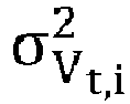
- It is particularly preferable if a variance of the single velocity magnitude estimate can be calculated using an uncertainty propagation. In this way an estimated orientation uncertainty is incorporated to improve the estimation of the velocity magnitude.
- Advantageously the uncertainty propagation satisfies the following condition:


- Preferably the uncertainty propagation satisfies the following condition:


- It is preferred if a variance estimation of the estimated velocity magnitude is carried out, preferably wherein the variance of the estimated velocity magnitude is estimated using weights. This results in improved calculation results that further improve the accuracy of the method.
- Preferably the weights satisfy the following condition:


- It is preferred if a plausibility check for the estimated velocity magnitude is carried out, preferably wherein the plausibility check is based on an estimated variance of the velocity magnitude, wherein the estimated variance satisfies the following condition:

- According to a further aspect the present invention further relates to a radar detection system comprising an emitter that is configured to send out a radar signal, a plurality of detection channels that are respectively configured to detect radar signals reflected in the field of view of the radar detection system in a single measurement instance and an evaluation unit, the evaluation unit of the radar detection system being configured to resolve multiple points of reflection from a moving target in a single measurement instance, wherein each of the resolved points of reflection is described by data relating to a range, an azimuth angle and a raw range rate of the points of reflection in said single radar measurement instance, the evaluation further being configured to carry out a method in accordance with the teaching present herein or an object hypothesis algorithm that is compiled to carry out a method in accordance with the teaching presented herein. The advantages achieved by the method discussed in the foregoing can thereby beneficially be incorporated into such a radar detection system.
- The invention is further described by way of example with reference to the accompanying drawings in which:
-
Figure 1 shows a target coordinate system; -
Figure 2 shows a vehicle coordinate system; -
Figure 3 shows a sensor coordinate system; -
Figure 4 shows a target vehicle with respect to a host vehicle with points of reflection located on the target vehicle; -
Figure 5 illustrates principles of calculating velocity vectors at the location of a point of reflection; -
Figure 6 shows longitudinal and lateral components of the velocity vectors for two points of reflection of the target; -
Figure 7 shows radial and tangential components of the velocity vector for two points of reflection of the target; -
Figure 8 shows a heading of velocity vector for two points of reflection of the target; -
Figure 9 shows a drawing describing the aspect angle of detection; -
Figure 10 shows a process flow for an object hypotheses velocity run algorithm; -
Figure 11 shows a heading deviation comparison of proposed algorithm and velocity profile estimates in the case of not plausible velocity profile estimations; and -
Figure 12 shows a magnitude deviation comparison of proposed algorithm and velocity profile estimates in the case of non-plausible velocity profile estimations. - Generally, a host vehicle 4 (see
Fig. 2 ) is equipped with a radar system 5' (seeFig. 2 ) where reflected radar signals from a target 2 (Fig. 1 ) in the field of view of the radar system 5' are processed to provide data in order to ascertain the parameters used in the methodology. - In order to do this various conditions and requirements are required. The target 2 (rigid body, e.g. vehicle) needs to be an extended target, i.e., the target allows the determination of a plurality of points of
reflection 6' (seeFig. 4 ) that are reflected from thetarget 2 in real-time and that are based on raw radar detection measurements. - So, as used herein, the term "extended target" is used to refer to
targets 2 that are capable of providing multiple, i.e. two, three or more spaced-apart scattering-points 6' also known as points ofreflection 6'. The term "extended target" is thus understood as atarget 2 that has some physical size. In this instance it should be noted that the physical size can be selected e.g. in the range of 0.3 m to 20 m in order to be able to detect points ofreflection 6' stemming from e.g. a moving person to a moving heavy goods vehicle or the like. - The
various scattering points 6' are not necessarily individually tracked from one radar scan to the next and the number of scatteringpoints 6' can be a different between scans. Furthermore, the locations of the scattering points 6' can be different on theextended target 2 in successive radar scans. - Radar points of
reflection 6' can be determined by thehost vehicle 4 from radar signals reflected from thetarget 2, wherein a comparison of a given reflected signal with an associated emitted radar signal can be carried out to determine the position of the radar point ofreflection 6', e.g., in Cartesian or Polar coordinates (azimuth angle, radial range) with respect to the position of a radar-emitting and/or radar-receiving element/unit on the host vehicle, which can be the position of the radar sensor unit. - By using, e.g., Doppler radar techniques, the range rate is also determined as known in the art. It is to be noted that the "raw data" from a single radar scan can provide the parameters θi (azimuth angle) and ṙi (raw range rate, i.e., radial velocity) for the i-th point of reflection of n points of reflection. These are the parameters which are used to estimate the velocity of a (moving) target, wherein

- It is also to be noted that the term instantaneous radar scan, single radar scan or single measurement instance can include reflection data from a "chirp" in Doppler techniques, which may scan over, e.g., up to 2ms. This is well known in the art. In the subsequent description, the following conventions and definitions are used:
-
Fig. 1 shows an illustration of a world coordinate system with theorigin 1 fixed to a point in space- it is assumed that this world coordinate system does not move and does not rotate in the following mathematical description. Conventionally, the coordinate system is right-handed; the Y-axis, orthogonal to the X-axis, pointing to the right; the Z-axis pointing into the page and a an azimuth angle is defined in positive direction (clock-wise) with respect to the X-axis.Fig. 1 further shows theextended target 2 in the form of a vehicle, e.g. an object having a length of approximately 4.5 m. -
Fig. 2 shows a vehicle coordinate system that in the present instance has itsorigin 3" located at the center of thefront bumper 3 of ahost vehicle 4. It should be noted in this connection that theorigin 3" of the vehicle coordinate system can be arranged at different positions at thehost vehicle 4. - In the present instance the X-axis is parallel to the longitudinal axis of the
vehicle 4, i.e. it extends between thefront bumper 3 and a rear bumper 3' and intersects with the center of thefront bumper 3 if theorigin 3" is located there. The vehicle coordinate system is right-handed with the Y-axis orthogonal to the X-axis and pointing to the right, the Z-axis pointing into the page. An (azimuth) angle is defined as in the world coordinate system. -
Fig. 3 shows a sensor coordinate system having theorigin 5. In the example ofFig. 3 theorigin 5 is located at the center of a sensor unit 5', which can be a radome. The X-axis is perpendicular to the sensor radome, pointing away from the radome. The coordinate system is right-handed: Y-axis orthogonal to the X-axis and pointing to the right; Z-axis pointing into the page. An (azimuth) angle is defined as in the world coordinate system. - The velocity and the yaw rate of the
host vehicle 4 are assumed to be known from sensor measurements known in the art. The over-the-ground (OTG) velocity vector of thehost vehicle 4 is defined as:
- In this connection it should be noted that the radar detection system 5' comprises an emitter that is configured to send out a radar signal, a plurality of detection channels that are respectively configured to detect radar signals reflected in a field of view of the radar detection system in a single measurement instance, and an evaluation unit (all not shown). The evaluation unit of the radar detection system 5' is configured to resolve multiple points of
reflection 6' from the movingtarget 2 in a single measurement instance, wherein each of the resolved points ofreflection 6' is described by data relating to a range ri , an azimuth angle θi and a raw range rate ṙi of the points ofreflection 6' in said single radar measurement instance. The evaluation is further configured to carry out a method of estimating a velocity magnitude as discussed in the following respectively an object hypothesis algorithm that is compiled to carry out such a method of estimating a velocity magnitude. - The sensor mounting position and boresight angle with respect to the vehicle coordinate system are assumed to be known with respect to the vehicle coordinate system (VCS), wherein the following notations are used (see also
Fig. 9 in this regard): - xs,VCS - sensor mounting position with respect to longitudinal (X-) coordinate
- ys,VCS - sensor mounting position with respect to lateral (Y) coordinate
- γs,VCS - sensor boresight angle.
- The sensor over-the-ground (OTG) velocities can be determined from the known host vehicle velocity and the known sensor mounting position. It is understood that more than one sensor 5' can be integrated into one
vehicle 4 and specified accordingly. - The sensor OTG velocity vector is defined as:


- Similarly the sensor(s) OTG velocities are assumed to be known, as they can be determined from the host vehicle motion and the sensor mounting positions, such that the sensor velocity vector is:

- At each radar look (or single measurement instance), the sensor 5' captures m raw points of
reflection 6' from thetarget 2. Each raw detection is described by the following parameters expressed in the sensor coordinate system: - ri - range (or radial distance)
- θi - azimuth angle
- ṙi - raw range rate (or radial velocity)
- i = 1,...,m
- Following this the target planar motion can be equivalently described by the target yaw rate and center of rotation (with
targets 2 having non-zero yaw rate)
-
Fig. 5 shows a velocity vector at the location ofraw detections 6' captured from arigid body target 2. Thecenter 7 of rotation of thetarget 2 is also indicated. -
Fig. 6 shows longitudinal and lateral components of the velocity vectors for two points ofreflection 6' of thetarget 2. The longitudinal and lateral velocity components for each point of rigid body can be described as
V t,i being the velocity vector of i-th point of rigid body,

-
Fig. 7 shows radial and tangential components of the velocity vector for twopoints 6' of detection of thetarget 2. The radial and tangential velocity components for each point of rigid body can be described as: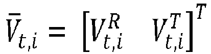


-
Fig. 8 shows a heading of velocity vector for twopoints 6' of detection of thetarget 2. The heading and velocity magnitude for each point of rigid body can be described as:
- In the case of straight moving targets 2 (i.e. the yaw rate of the
target 2 is equal to zero), the velocity vector for each point ofreflection 6' of the rigid body is the same and is described as:
-
Fig. 9 shows a drawing describing the aspect angle of detection. The orientation of thetarget 2 is denoted by γt . The aspect angle is defined as a difference between orientation angle and azimuth angle of the point of the interest: αa,i = γt - θi - The sensor boresight is aligned with the X-axis of the sensor 5', i.e. it intersects with the origin 5 (see
Fig. 3 ). The orientation angle, the azimuth of detection and the aspect angle of detection are all determined relative to the sensor boresight as indicated by the respective arrows that extend between the X-axis and the Y-axis and that end at points in the X-Y plane relative to thetarget 2. - The range rate equation for a single raw detection can be expressed as follows:

detection point 6, as illustrated inFig. 5 . The location of thedetection point 6 can be described by the azimuth angle θ i=1 and the value of the radial distance r i=1 (range of detection point, i.e. distance between origin and the detection point). - To simplify the notation, the notion of a compensated range rate is introduced and defined as:

host vehicle 4. The compensated range rate can also be expressed as:
- The range rate equation can be expressed in vector form as:

- Similarly the range rate equation in vector form with two components can be expressed as:

target 2 to which a plurality ofdetection points 6 refer and on which basis the coefficients have been determined. - This means that the velocity profile equation is assumed to be valid not only for specific points of
reflection 6' but for a range of azimuth angles. Therefore, the range rate can readily be determined for any azimuth angle from a specific angle range using the range rate equation. - As the skilled person understands, in practice, the "true" coefficients ct, st can only be estimated from a plurality of detection points. These estimates are denoted c̃t and s̃t and are estimated using an iteratively (re-) weighted least squares methodology.
- In the present teaching the velocity profile is used as a synonym of the components of the range rate equation and can be expressed as:

VP being the velocity profile. It should be noted that estimated values are denoted with a hat, least square solutions are denoted with a tilde and vectors are denoted with a line. - In order to carry out the detection of the velocity magnitude several conditions have to be satisfied. These conditions comprise at least some of the following:
- several raw detections from the
same target 2 should be recorded as points ofreflection 6' (it is preferable if at least two, more specifically at least three and especially preferable if at least four such raw detections are made to produce two, three, four ormore points 6' of detection in the following); - each raw detection is preferably attributed with a position in the sensor FOV (field of view) that comprises polar (azimuth angle - θi , range - ri ) components and the range rate ṙi ;
- a cluster containing a set of
points 6' of detections from the same target 2 (the set comprising at least one and preferably at least twopoints 6' of detections) should be detected; - the accuracy of detection attributes is assumed to be known, with the azimuth angle accuracy being σθ and the range rate accuracy being σ ṙ ;
- the orientation angle is estimated as γt ;
- the uncertainty of orientation angle is estimated as σγt ;
- and/or the information that a velocity estimation not available or not plausible.
- The teaching presented herein thereby provides an improved method of estimating the velocity magnitude of the
extended target 2, which includes the valid estimation of the orientation angle and takes into account invalid motion estimations. Before summarizing the invention the prior art will initially be discussed to provide an overview and an introduction to the subject matter presented herein. - An algorithm for a geometrical approach to the estimation of the orientation of extended radar targets has previously been considered. In this approach the proposed solution does not rely on time filtering and works only on a single radar measurement. The algorithm is based on a version of the rotating calipers algorithm. The solution of this algorithm relies on the determination of a convex hull that includes all detections assigned to a single target. The bounding box is spread to extreme values of Euclidian positions of its point detections and then it is rotated so that in each step it is collinear with one side of the convex hull.
- An enhancement of this method ignores consecutive convex hull points iteratively, because erroneous detections may lie outside the vehicle and may not reflect the actual shape of bounding box.
- For each fitted bounding box the quality factor is evaluated by means:
- The size of bounding box, which should be as small as possible
- The distance of each detection to the nearest side of resulting target OBB. Such distances are summed over all detections and minimized. The distance to the nearest side has to be calculated differently for inliers and outliers.
- As an alternative algorithm for the same task a brute-force algorithm was also considered. In this alternative it was demonstrated that the solution works for an estimation of the orientation for vehicles represented by OBB (Oriented Bounding Box). Again, the OBBs were estimated using Euclidean position of detections from a single radar measurement. The main drawback of that solution is a significant computation time and a requirement for a relatively high number of detections captured from target vehicle.
- There are several different algorithms for estimating object orientation. They are also based on geometrical alignment of detections in Euclidian coordinate system, e.g.: L-fit, Hough transform.
- The case of a straight-line moving distributed target has also been considered. This restriction simplifies the estimation problem as the velocity vectors at the location of each raw detections are identical, i.e.:


- This was achieved by Least Square solution to the problem defined as follows:

- The algorithm proved to be a very effective technique for instantaneous estimation of target velocity.
- In a similar manner the same problem and the same theoretical basis for the estimation of lateral velocity of a straight line moving object was considered. In that example an enhancement of the Cloud Algorithm was proposed by means of:
- Executing RANSAC algorithm to identify outliers
- Executing orthogonal distance regression (ODR) to solve error-in-variables problem for a modified formulation of the original problem.
- In this solution the improved robustness of the algorithm is presented in comparison to the original Cloud Algorithm solution. However, computational complexity and the requirement to solve an optimization problem are the major drawbacks of the proposed approach, especially when an application in a production embedded system is to be considered.
- Further work has taken place in which the cloud algorithm was applied to the estimation of target's motion without the restriction on straight-line path was investigated. Such a situation is shown in
Figure 5 . The over-the-ground velocity vectors at the location of each detection are determined as follows:
- The range rate equation for each raw detection was derived to be:

- This equation can be reduced since:


- It should be noted in this connection that the range measurement does not appear in the above equation, thus it is not required for the velocity estimation.
- It was then shown that the Least Square solution to this problem results in:


- The estimator of the velocity of the i-th detection is:


- Although the Least Square solution does not estimate the velocity vector itself, it can still be treated as a biased velocity vector estimator in case of yawing target. Thus, velocity profile estimation can be used as a valuable information for velocity vector estimation in both cases: straight-line moving and turning target.
- In statistics, the use of inverse-variance weighting is a method of aggregating two or more random variables to minimize the variance of the weighted average. In such methods each random variable is weighted in inverse proportion to its variance:

- µ̂x - Estimated mean of sample
- xi - Single sample
-

- The main advantage of variance is that samples with higher uncertainty have lower influence on the estimation.
- To work correctly each sample variance has to be known or at least estimated. If sample uncertainty is not known or cannot be estimated then inverse-variance weighting cannot be applied. If each sample variance is equal then equation is reduced to simple sample mean. Furthermore, if the sample variance does not vary a lot, the advantages of using inverse-variance weighting is questionable.
- However, the following restrictions and limitations exist with respect to the prior art. The velocity vector is usually estimated using the Cloud Algorithm (velocity profile). The problem with this estimation is that it is a valid velocity estimation only in the case of straight moving targets. But even for some straight moving targets, the distribution of detections may be such that the estimate cannot be treated as reliable.
- Additionally, when the target is maneuvering the Velocity Profile solution cannot be treated as velocity estimation. It can only be treated as a biased velocity estimation, but usually it is completely unreliable. Velocity can only be plausibly calculated if the yaw rate of the target is reliably estimated. This is rarely possible using automotive Doppler radars.
- On the other hand, when some conditions are met, the orientation of the target can be estimated from a spatial distribution of extended target raw detections. Thus, cases exist where the velocity estimation based on the velocity profile is unreliable and an orientation estimation is reliable. In these cases a position, an orientation and a dimension can be estimated, but the velocity is not estimated (as it is unreliable) in which case the information which comes from the range rates measurements is then completely ignored.
- In the proposed algorithm for the velocity estimation discussed herein the following case is proposed and discussed in detail:
The contribution of the present invention includes: - An algorithm for velocity estimation of extended target
- An algorithm for variance estimation for estimated velocity
- The features of this invention are that the velocity can be estimated even when the velocity estimated by other algorithms is unreliable, the known measurement accuracy is incorporated in the invention to improve the velocity estimation. Moreover, an estimated orientation uncertainty can be incorporated to improve the velocity estimation. Thereby the availability of the velocity estimation is improved. The approach taken in principle does not require any filtering/tracking to take place. The algorithm is suitable for application in production embedded systems because of its low computational complexity which leads to a reduced computational time in comparison to prior art methods and hence makes this method more facile than prior art methods. Moreover, an estimation of the yaw rate estimation is not required which further reduces the computational demand in effort and cost.
- The method of the invention of estimating a velocity magnitude of a moving
target 2 in a horizontal plane is based on using radar signals received by a radar detection system 5'. - The radar system 5' includes a radar sensor unit that is arranged at the
front bumper 3 inFig. 3 having theorigin 5 and that is adapted to receive signals emitted from saidhost vehicle 4 and reflected by saidtarget 2. The radar sensor unit 5' also known as a radar detection system 5' is configured to resolve multiple dominant points ofreflection 6' from the movingtarget 2 in a single measurement instance. Each of the resolved points ofreflection 6' is described by data relating to the range ri , the azimuth angle θi and the raw range rate ṙi of the points ofreflection 6' in said single radar measurement instance. - The method comprises the following steps:
In order to carry out the invention the heading angle is assumed to be the same as the orientation angle instep 1. The heading angle can be expressed as follows:
- In
Step 2 the estimate of thetarget 2 velocity magnitude is calculated as a weighted mean of multiple estimates Vt,i - that are estimated from each range rate ṙi and azimuth θi from the points ofreflection 6' and heading angle, with the heading angle being the assumed value. The multiple estimates can be expressed as:
- These measurements are performed in one single radar measurement instance and are based on estimated points of
reflections 6' that satisfy a predetermined condition. The one condition may be that the range rate measurements are deemed to be valid range rate measurements. Thus, said resolved points ofreflection 6' of said range rate are verified prior to the step of calculating the velocity magnitude as a weighted mean of estimates. -
Step 2 comprises sub step 2.1, in which each detection of the point ofreflection 6' is validated to see if the velocity magnitude can be plausibly estimated. It is found that the detection is valid if e.g.
- In sub step 2.2 the velocity magnitude of the
target 2 can be calculated as a single estimate of the velocity magnitude of thetarget 2 as:
- In sub step 2.3 - the important design step - during the step of estimating the weighted means of estimates, the weights are selected as an inverse of estimated variance for a corresponding estimate. This can be expressed as:


- From this the variance of a single velocity magnitude estimate can be calculated using an uncertainty propagation. The uncertainty propagation can satisfy the following condition:


- In this connection it should be noted that the estimation of the variance of the estimated velocity magnitude can be based on the assumption that the heading variance should be higher than the estimated orientation variance. The heading variance can differ from the orientation angle and this can be expressed as:

- Simplifying the above equations, the uncertainty propagation, i.e. the final weight equation can be expressed as:

- In step 3 a variance estimation of an estimated velocity magnitude can take place. The variance estimation of the estimated velocity magnitude can be estimated using weights. The weights can be expressed as:

- In step 4 a plausibility check for the estimated velocity magnitude can take place. This plausibility check is applied in order to reduce the number of unreliable estimations. It has been found that the simplest plausibility check is based on an estimated variance of the velocity magnitude. In this connection the estimated variance is assumed to satisfy a condition. This condition can be expressed as: If

- The proposed algorithm was implemented in a vehicle in order to assess the performance of an object hypotheses algorithm. The proposed object hypotheses algorithm is used for velocity estimation in case of valid orientation estimation and invalid velocity estimation.
-
Fig. 10 shows a flow chart indicated the steps of the process flow of the object hypotheses velocity run algorithm that can be implemented in the evaluation unit of the radar detection system 5'. The process starts atbox 20 at box 22 a decision is made whether the object hypotheses model is a point model or not. - If the decision is made that the object hypotheses model is a point model, then a decision is made at
box 24 whether the azimuth rate is invalid. - If this is the case then a velocity status of the nearest detection is verified at
box 26. If a decision is made that the velocity status of the nearest detection is verified then a decision is made atbox 28 that the range rate is the same as the dealiased range rate of the nearest detection. - This information is passed on to the
box 30 that outputs corresponding information tobox 32 which is the node point for all decisions and determinations of the object hypotheses velocity run algorithm that are generally output atbox 34. - If the decision is made that the velocity status of the nearest detection cannot be verified at
box 26 then a decision is made atbox 36 that the range rate is invalid. This information is passed on to thebox 30 that outputs corresponding information tobox 32 which is the node point for all decisions and determinations of the object hypotheses velocity run algorithm that are generally output at thebox 34. - If the decision is made that the object hypotheses model is not a point model at
box 22, then a determination is made atbox 38 whether the velocity angle is valid. If this is the case then this information is passed to box 40 that further forwards this information tobox 42. - At box 42 a decision is made whether one of the longitudinal velocity of detection group and the lateral velocity of detection group is invalid. If this is the case the process moves on to
box 44 where a determination is made that the azimuth rate is invalid. This information is forwarded tobox 46 where a decision is made that the range rate is invalid. This information is forwarded tobox 48 that in turn forwards the information to thebox 32 for final output at thebox 34. - If a decision is made at the
box 38 that the velocity angle is not valid then this information is passed on tobox 50 where a decision is made to see whether the number of reliable detections is above a desired threshold value or not or whether the ratio of the reliable detections is above a certain threshold or not. If the determination is made that the reliable detections or the ratio of reliable detections is below the desired threshold then this information is passed to thebox 40 that further forwards this information to thebox 42. - If the determination is made that the reliable detections or the ratio of reliable detections is above the desired threshold then this information is passed to
box 50 in order to calculate the over the ground velocity OTG from the heading angle. The result of this calculation is then forwarded tobox 40 that further forwards this information tobox 42. - If at the box 42 a decision is made that one of the longitudinal velocity of detection group and the lateral velocity of detection group is valid then corresponding reference point velocities are calculated at
box 54. This information is then passed on tobox 48 for output at thebox 34. - The performance of the proposed object hypothesis algorithm was evaluated with reference data. For this purpose 500 test cases were executed with different road scenarios.
- Tables 1 and 2 present the statistics of the velocity availability. In comparison to prior art velocity magnitude estimates, the number of invalid velocity estimation was reduced by more than 10 times using the proposed algorithm.
Table 1 shows the number of samples used for different velocity estimation algorithms. Velocity Profile Proposed algorithm Velocity invalid Number of samples 20666 2113 198 Percent of samples [%] 89.9 9.2 0.8 Table 2 shows the availability of velocity estimation with and without algorithm. Valid Invalid Without proposed algorithm 20666 [89.9%] 2311 [10%] With proposed algorithm 22779 [99.2%] 198 [0.8%] -
Figure 11 shows a heading deviation comparison of the proposed algorithm (solid line) and velocity profile estimates (dashed line) in case of non-plausible velocity profile estimations. -
Figure 12 shows a magnitude deviation comparison of proposed algorithm (solid line) and velocity profile estimates (dashed line) in case of not plausible velocity profile estimations. - In
Figs. 11, 12 and in table 3 the accuracy of the algorithm is presented. To compare accuracy performance velocity profile estimates were used on the corresponding samples. It should be noted that the velocity profile estimates were previously classified as not reliable, so presented statistics illustrate situation when no plausibility checks would be applied for the velocity profile and proposed algorithm would not be implemented. - As indicated the accuracy improvement for these samples is significant and it is believed that this algorithm works significantly better than initial intuition of the inventors would have expected.
- It should further be noted that this estimation is achieved using less computing power than was previously used for less reliable estimations such as those suggested in the prior art. One of the main reasons for this is that the velocity magnitude can be estimated using a single radar detection system 5' in only one single radar measurement instance.
Table 3 shows an accuracy comparison of proposed algorithm and velocity profile estimates in case of non-plausible velocity profile estimations. RMS Velocity Profile Proposed algorithm Heading [deg] 101 19 Magnitude [km/h] 32 18
Claims (14)


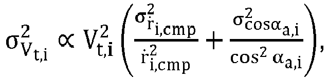


Priority Applications (3)
| Application Number | Priority Date | Filing Date | Title |
|---|---|---|---|
| EP18173846.9A EP3572839A1 (en) | 2018-05-23 | 2018-05-23 | Method of estimating a velocity magnitude of a moving target in a horizontal plane and radar detection system |
| US16/386,691 US11448746B2 (en) | 2018-05-23 | 2019-04-17 | Method of estimating a velocity magnitude of a moving target in a horizontal plane and radar detection system |
| CN201910409130.3A CN110531357B (en) | 2018-05-23 | 2019-05-16 | Method and Radar Detection System for Estimating the Velocity of Moving Target in Horizontal Plane |
Applications Claiming Priority (1)
| Application Number | Priority Date | Filing Date | Title |
|---|---|---|---|
| EP18173846.9A EP3572839A1 (en) | 2018-05-23 | 2018-05-23 | Method of estimating a velocity magnitude of a moving target in a horizontal plane and radar detection system |
Publications (1)
| Publication Number | Publication Date |
|---|---|
| EP3572839A1 true EP3572839A1 (en) | 2019-11-27 |
Family
ID=62244311
Family Applications (1)
| Application Number | Title | Priority Date | Filing Date |
|---|---|---|---|
| EP18173846.9A Withdrawn EP3572839A1 (en) | 2018-05-23 | 2018-05-23 | Method of estimating a velocity magnitude of a moving target in a horizontal plane and radar detection system |
Country Status (3)
| Country | Link |
|---|---|
| US (1) | US11448746B2 (en) |
| EP (1) | EP3572839A1 (en) |
| CN (1) | CN110531357B (en) |
Cited By (2)
| Publication number | Priority date | Publication date | Assignee | Title |
|---|---|---|---|---|
| EP4166978A1 (en) * | 2021-10-15 | 2023-04-19 | Aptiv Technologies Limited | Target-velocity estimation using position variances |
| EP4549997A1 (en) * | 2023-11-02 | 2025-05-07 | Samsung Electronics Co., Ltd | Radar method and apparatus with target velocity measurement |
Families Citing this family (25)
| Publication number | Priority date | Publication date | Assignee | Title |
|---|---|---|---|---|
| EP3415945B1 (en) | 2017-06-12 | 2024-01-10 | Aptiv Technologies Limited | Method of determining the yaw rate of a target vehicle |
| EP3415948B1 (en) * | 2017-06-12 | 2021-11-10 | Aptiv Technologies Limited | A method of determining the de-aliased range rate of a target |
| EP3575827B1 (en) | 2018-06-01 | 2024-07-31 | Aptiv Technologies AG | Method for robust estimation of the velocity of a target using a host vehicle |
| EP3611541B1 (en) | 2018-08-16 | 2024-07-03 | Aptiv Technologies AG | Method of determining an uncertainty estimate of an estimated velocity |
| CN112050830B (en) * | 2019-06-06 | 2023-06-02 | 华为技术有限公司 | Motion state estimation method and device |
| JP7351706B2 (en) * | 2019-10-15 | 2023-09-27 | 株式会社Soken | object tracking device |
| FI131712B1 (en) * | 2020-01-17 | 2025-10-08 | Teknologian Tutkimuskeskus Vtt Oy | Improving angular resolution of radars using an artificial neural network |
| US11586862B2 (en) * | 2020-02-14 | 2023-02-21 | Ford Global Technologies, Llc | Enhanced object detection with clustering |
| US11719821B2 (en) | 2020-02-21 | 2023-08-08 | BlueSpace.ai, Inc. | Method for object avoidance during autonomous navigation |
| CN111679270B (en) * | 2020-05-26 | 2022-05-03 | 电子科技大学 | A Multi-Path Fusion Target Detection Algorithm for Uncertain Reflection Points |
| US11714186B2 (en) * | 2020-09-02 | 2023-08-01 | Inceptio Hongkong Limited | Estimating target heading using a single snapshot |
| US11709250B2 (en) * | 2020-09-02 | 2023-07-25 | Inceptio Hongkong Limited | Estimating three-dimensional target heading using a single snapshot |
| DE102021202641A1 (en) * | 2021-03-18 | 2022-09-22 | Robert Bosch Gesellschaft mit beschränkter Haftung | Method for determining a state of motion of a rigid body |
| JP7614387B2 (en) * | 2021-03-24 | 2025-01-15 | コンチネンタル・オートナマス・モビリティ・ジャーマニー・ゲゼルシャフト・ミト・ベシュレンクテル・ハフツング | A method for modeling sensor uncertainty in central-level tracking architectures. |
| CN113109783B (en) * | 2021-04-15 | 2022-08-26 | 森思泰克河北科技有限公司 | Course angle acquisition method, device, equipment and storage medium |
| EP4160256A1 (en) * | 2021-10-01 | 2023-04-05 | Aptiv Technologies Limited | Method and system for calibrating a radar sensor |
| CN115963485A (en) * | 2021-10-11 | 2023-04-14 | 华人运通(上海)自动驾驶科技有限公司 | Speed detection method, device, equipment and readable storage medium |
| DE102021129070A1 (en) * | 2021-11-09 | 2023-05-11 | Valeo Schalter Und Sensoren Gmbh | Recording of the content of an environment of a vehicle with a priori confidences |
| US12428029B2 (en) * | 2021-11-16 | 2025-09-30 | Ford Global Technologies, Llc | Systems and methods for estimating cuboid headings based on heading estimations generated using different cuboid defining techniques |
| EP4187276A1 (en) * | 2021-11-30 | 2023-05-31 | Aptiv Technologies Limited | Method and system for estimating a radar calibration matrix |
| EP4194885B1 (en) * | 2021-12-09 | 2025-10-15 | Aptiv Technologies AG | Method for determining the mobility status of a target object |
| US20230204763A1 (en) * | 2021-12-29 | 2023-06-29 | Tusimple, Inc. | Radar measurement compensation techniques |
| US12487347B2 (en) | 2021-12-30 | 2025-12-02 | BlueSpace.ai, Inc. | Method for calibrating offsets between doppler-based sensors on a mobile platform |
| CN115541927A (en) * | 2022-10-27 | 2022-12-30 | 无锡睿尔特智能科技有限公司 | Surface water flow velocity processing method based on velocity grid statistics |
| US12535575B2 (en) * | 2023-06-08 | 2026-01-27 | Nvidia Corporation | Object tracking using radar for autonomous systems and applications |
Citations (3)
| Publication number | Priority date | Publication date | Assignee | Title |
|---|---|---|---|---|
| EP2307908A1 (en) * | 2008-07-31 | 2011-04-13 | Mitsubishi Electric Information Technology Centre Europe B.V. | Automotive radar with composite multi-slope fm chirp waveform |
| DE102013011239A1 (en) * | 2013-07-05 | 2015-01-08 | Daimler Ag | Method for determining a movement of an object |
| DE102013018310A1 (en) * | 2013-10-31 | 2015-04-30 | Daimler Ag | Method for determining a movement of an object |
Family Cites Families (39)
| Publication number | Priority date | Publication date | Assignee | Title |
|---|---|---|---|---|
| US5964822A (en) | 1997-08-27 | 1999-10-12 | Delco Electronics Corp. | Automatic sensor azimuth alignment |
| US6873251B2 (en) * | 2002-07-16 | 2005-03-29 | Delphi Technologies, Inc. | Tracking system and method employing multiple overlapping sensors |
| US6925370B2 (en) | 2003-10-06 | 2005-08-02 | Delphi Technologies, Inc. | Automotive system including a back-up aid with parking assist |
| US7831354B2 (en) | 2004-03-23 | 2010-11-09 | Continental Teves, Inc. | Body state estimation of a vehicle |
| KR20080007780A (en) | 2006-07-18 | 2008-01-23 | 현대자동차주식회사 | Radar Steering with Adaptive Cruise Control System |
| JP2008116323A (en) * | 2006-11-06 | 2008-05-22 | Mitsubishi Electric Corp | Radar apparatus, distance measurement method and program thereof |
| JP4827956B2 (en) | 2009-09-18 | 2011-11-30 | 三菱電機株式会社 | Automotive radar equipment |
| DE102009057191A1 (en) * | 2009-12-05 | 2011-06-09 | Valeo Schalter Und Sensoren Gmbh | Method for uniquely determining a distance and / or a relative speed of an object, driver assistance device and motor vehicle |
| CN102822881B (en) * | 2010-04-05 | 2015-04-29 | 丰田自动车株式会社 | Vehicle collision judgment device |
| WO2012001896A1 (en) | 2010-06-29 | 2012-01-05 | 本田技研工業株式会社 | Device for estimating vehicle travel path |
| DE102012224125B4 (en) | 2012-01-02 | 2024-03-07 | Ford Global Technologies, Llc | Method for lane keeping support for a driver of a motor vehicle and lane keeping assistance system |
| US8457891B1 (en) | 2012-06-19 | 2013-06-04 | Honeywell International Inc. | Systems and methods for compensating nonlinearities in a navigational model |
| US9187091B2 (en) | 2012-07-30 | 2015-11-17 | Ford Global Technologies, Llc | Collision detection system with a plausibiity module |
| JP5905846B2 (en) * | 2013-03-29 | 2016-04-20 | 株式会社日本自動車部品総合研究所 | Crossing determination device and program |
| WO2015050596A2 (en) | 2013-06-15 | 2015-04-09 | Howard University | Using an mm-principle to enforce a sparsity constraint on fast image data estimation from large image data sets |
| KR101528882B1 (en) | 2013-07-19 | 2015-06-15 | 현대모비스 주식회사 | Apparatus and method for correcting offset of yaw-rate sensor and system for controlling velocity of vehicle with the said apparatus |
| CA2824703C (en) | 2013-08-26 | 2021-03-16 | Alastair Malarky | Methods and systems for determining vehicle position in an automatic vehicle identification system |
| GB2517710A (en) * | 2013-08-28 | 2015-03-04 | Aveillant Ltd | Radar system and associated apparatus and methods |
| DE102013019804A1 (en) | 2013-11-27 | 2015-05-28 | Daimler Ag | Method for determining a movement of an object |
| JP6248593B2 (en) | 2013-12-06 | 2017-12-20 | 富士通株式会社 | Posture detection apparatus, posture detection method, and posture detection program |
| DE102015101292A1 (en) | 2015-01-29 | 2016-08-04 | Valeo Schalter Und Sensoren Gmbh | Method for detecting an object in an environmental region of a motor vehicle by checking a spatial deviation of measuring points, control device, driver assistance system and motor vehicle |
| US9903945B2 (en) | 2015-02-04 | 2018-02-27 | GM Global Technology Operations LLC | Vehicle motion estimation enhancement with radar data |
| US9983301B2 (en) | 2015-10-02 | 2018-05-29 | Delphi Technologies, Inc. | Automated vehicle radar system to determine yaw-rate of a target vehicle |
| US10565468B2 (en) | 2016-01-19 | 2020-02-18 | Aptiv Technologies Limited | Object tracking system with radar/vision fusion for automated vehicles |
| EP3252501B1 (en) | 2016-06-03 | 2022-06-08 | Veoneer Sweden AB | Enhanced object detection and motion state estimation for a vehicle environment detection system |
| JP6619697B2 (en) * | 2016-06-09 | 2019-12-11 | 株式会社デンソー | Radar equipment |
| US10286916B2 (en) | 2016-06-20 | 2019-05-14 | Aptiv Technologies Limited | Trailer estimation and blind spot information system performance improvement |
| US10351146B2 (en) | 2016-06-20 | 2019-07-16 | Aptiv Technologies Limited | Trailer estimation improvement |
| US10114106B2 (en) | 2016-07-22 | 2018-10-30 | Delphi Technologies, Inc. | Automated vehicle radar system with auto-alignment for azimuth, elevation, and vehicle speed-scaling-error |
| CN106372278A (en) | 2016-08-19 | 2017-02-01 | 电子科技大学 | Sensitivity analysis method jointly considering input parameter uncertainty and proxy model uncertainty |
| EP3285230B1 (en) | 2016-08-19 | 2021-04-07 | Veoneer Sweden AB | Enhanced object detection and motion estimation for a vehicle environment detection system |
| EP3415948B1 (en) | 2017-06-12 | 2021-11-10 | Aptiv Technologies Limited | A method of determining the de-aliased range rate of a target |
| EP3415945B1 (en) | 2017-06-12 | 2024-01-10 | Aptiv Technologies Limited | Method of determining the yaw rate of a target vehicle |
| EP3422042B1 (en) | 2017-06-29 | 2020-03-18 | Aptiv Technologies Limited | Method to determine the orientation of a target vehicle |
| WO2019187056A1 (en) * | 2018-03-30 | 2019-10-03 | アルウェットテクノロジー株式会社 | Velocity measurement device, velocity measurement program, recording medium, and velocity measurement method |
| US10955547B2 (en) | 2018-05-24 | 2021-03-23 | The Boeing Company | Combined radar and communications system using common signal waveform |
| EP3575827B1 (en) | 2018-06-01 | 2024-07-31 | Aptiv Technologies AG | Method for robust estimation of the velocity of a target using a host vehicle |
| EP3611541B1 (en) | 2018-08-16 | 2024-07-03 | Aptiv Technologies AG | Method of determining an uncertainty estimate of an estimated velocity |
| US11046328B2 (en) * | 2018-09-25 | 2021-06-29 | GM Global Technology Operations LLC | Velocity estimation of an object |
-
2018
- 2018-05-23 EP EP18173846.9A patent/EP3572839A1/en not_active Withdrawn
-
2019
- 2019-04-17 US US16/386,691 patent/US11448746B2/en active Active
- 2019-05-16 CN CN201910409130.3A patent/CN110531357B/en active Active
Patent Citations (3)
| Publication number | Priority date | Publication date | Assignee | Title |
|---|---|---|---|---|
| EP2307908A1 (en) * | 2008-07-31 | 2011-04-13 | Mitsubishi Electric Information Technology Centre Europe B.V. | Automotive radar with composite multi-slope fm chirp waveform |
| DE102013011239A1 (en) * | 2013-07-05 | 2015-01-08 | Daimler Ag | Method for determining a movement of an object |
| DE102013018310A1 (en) * | 2013-10-31 | 2015-04-30 | Daimler Ag | Method for determining a movement of an object |
Cited By (3)
| Publication number | Priority date | Publication date | Assignee | Title |
|---|---|---|---|---|
| EP4166978A1 (en) * | 2021-10-15 | 2023-04-19 | Aptiv Technologies Limited | Target-velocity estimation using position variances |
| US12092723B2 (en) | 2021-10-15 | 2024-09-17 | Aptiv Technologies AG | Target-velocity estimation using position variance |
| EP4549997A1 (en) * | 2023-11-02 | 2025-05-07 | Samsung Electronics Co., Ltd | Radar method and apparatus with target velocity measurement |
Also Published As
| Publication number | Publication date |
|---|---|
| US20190361106A1 (en) | 2019-11-28 |
| CN110531357A (en) | 2019-12-03 |
| CN110531357B (en) | 2023-05-12 |
| US11448746B2 (en) | 2022-09-20 |
Similar Documents
| Publication | Publication Date | Title |
|---|---|---|
| US11448746B2 (en) | Method of estimating a velocity magnitude of a moving target in a horizontal plane and radar detection system | |
| US11125872B2 (en) | Method for robust estimation of the velocity of a target using a host vehicle | |
| US10634766B2 (en) | Method of determining the de-aliased range rate of a target | |
| US11994531B2 (en) | Method of determining an uncertainty estimate of an estimated velocity | |
| US10677907B2 (en) | Method to determine the orientation of a target vehicle | |
| US20240404273A1 (en) | Method and System for Indoor Multipath Ghosts Recognition | |
| US11249171B2 (en) | Method of determining an alignment error of an antenna and vehicle with an antenna and a detection device | |
| EP4194885B1 (en) | Method for determining the mobility status of a target object | |
| CN112368758B (en) | Methods for classifying the relevance of objects | |
| US12366644B2 (en) | Method and device for estimating a velocity of an object | |
| Ru et al. | Improvement on velocity estimation of an extended object | |
| EP4549992A1 (en) | Method for determining a pitch angle of an automobile radar | |
| US12248058B2 (en) | Track association based on azimuth extension and compactness errors |
Legal Events
| Date | Code | Title | Description |
|---|---|---|---|
| PUAI | Public reference made under article 153(3) epc to a published international application that has entered the european phase |
Free format text: ORIGINAL CODE: 0009012 |
|
| STAA | Information on the status of an ep patent application or granted ep patent |
Free format text: STATUS: THE APPLICATION HAS BEEN PUBLISHED |
|
| AK | Designated contracting states |
Kind code of ref document: A1 Designated state(s): AL AT BE BG CH CY CZ DE DK EE ES FI FR GB GR HR HU IE IS IT LI LT LU LV MC MK MT NL NO PL PT RO RS SE SI SK SM TR |
|
| AX | Request for extension of the european patent |
Extension state: BA ME |
|
| STAA | Information on the status of an ep patent application or granted ep patent |
Free format text: STATUS: REQUEST FOR EXAMINATION WAS MADE |
|
| 17P | Request for examination filed |
Effective date: 20200527 |
|
| RBV | Designated contracting states (corrected) |
Designated state(s): AL AT BE BG CH CY CZ DE DK EE ES FI FR GB GR HR HU IE IS IT LI LT LU LV MC MK MT NL NO PL PT RO RS SE SI SK SM TR |
|
| STAA | Information on the status of an ep patent application or granted ep patent |
Free format text: STATUS: EXAMINATION IS IN PROGRESS |
|
| 17Q | First examination report despatched |
Effective date: 20211126 |
|
| STAA | Information on the status of an ep patent application or granted ep patent |
Free format text: STATUS: THE APPLICATION IS DEEMED TO BE WITHDRAWN |
|
| 18D | Application deemed to be withdrawn |
Effective date: 20220407 |