EP3572648A1 - Spark assisted compression-ignition engine control - Google Patents
Spark assisted compression-ignition engine control Download PDFInfo
- Publication number
- EP3572648A1 EP3572648A1 EP19174810.2A EP19174810A EP3572648A1 EP 3572648 A1 EP3572648 A1 EP 3572648A1 EP 19174810 A EP19174810 A EP 19174810A EP 3572648 A1 EP3572648 A1 EP 3572648A1
- Authority
- EP
- European Patent Office
- Prior art keywords
- ivc
- engine
- combustion
- combustion chamber
- ignition
- Prior art date
- Legal status (The legal status is an assumption and is not a legal conclusion. Google has not performed a legal analysis and makes no representation as to the accuracy of the status listed.)
- Granted
Links
Images









Classifications
-
- F—MECHANICAL ENGINEERING; LIGHTING; HEATING; WEAPONS; BLASTING
- F02—COMBUSTION ENGINES; HOT-GAS OR COMBUSTION-PRODUCT ENGINE PLANTS
- F02D—CONTROLLING COMBUSTION ENGINES
- F02D41/00—Electrical control of supply of combustible mixture or its constituents
- F02D41/30—Controlling fuel injection
- F02D41/3011—Controlling fuel injection according to or using specific or several modes of combustion
- F02D41/3017—Controlling fuel injection according to or using specific or several modes of combustion characterised by the mode(s) being used
- F02D41/3035—Controlling fuel injection according to or using specific or several modes of combustion characterised by the mode(s) being used a mode being the premixed charge compression-ignition mode
- F02D41/3041—Controlling fuel injection according to or using specific or several modes of combustion characterised by the mode(s) being used a mode being the premixed charge compression-ignition mode with means for triggering compression ignition, e.g. spark plug
-
- F—MECHANICAL ENGINEERING; LIGHTING; HEATING; WEAPONS; BLASTING
- F02—COMBUSTION ENGINES; HOT-GAS OR COMBUSTION-PRODUCT ENGINE PLANTS
- F02B—INTERNAL-COMBUSTION PISTON ENGINES; COMBUSTION ENGINES IN GENERAL
- F02B37/00—Engines characterised by provision of pumps driven at least for part of the time by exhaust
- F02B37/12—Control of the pumps
- F02B37/16—Control of the pumps by bypassing charging air
-
- F—MECHANICAL ENGINEERING; LIGHTING; HEATING; WEAPONS; BLASTING
- F01—MACHINES OR ENGINES IN GENERAL; ENGINE PLANTS IN GENERAL; STEAM ENGINES
- F01L—CYCLICALLY OPERATING VALVES FOR MACHINES OR ENGINES
- F01L1/00—Valve-gear or valve arrangements, e.g. lift-valve gear
- F01L1/20—Adjusting or compensating clearance
- F01L1/22—Adjusting or compensating clearance automatically, e.g. mechanically
-
- F—MECHANICAL ENGINEERING; LIGHTING; HEATING; WEAPONS; BLASTING
- F02—COMBUSTION ENGINES; HOT-GAS OR COMBUSTION-PRODUCT ENGINE PLANTS
- F02B—INTERNAL-COMBUSTION PISTON ENGINES; COMBUSTION ENGINES IN GENERAL
- F02B11/00—Engines characterised by both fuel-air mixture compression and air compression, or characterised by both positive ignition and compression ignition, e.g. in different cylinders
-
- F—MECHANICAL ENGINEERING; LIGHTING; HEATING; WEAPONS; BLASTING
- F02—COMBUSTION ENGINES; HOT-GAS OR COMBUSTION-PRODUCT ENGINE PLANTS
- F02B—INTERNAL-COMBUSTION PISTON ENGINES; COMBUSTION ENGINES IN GENERAL
- F02B3/00—Engines characterised by air compression and subsequent fuel addition
- F02B3/06—Engines characterised by air compression and subsequent fuel addition with compression ignition
- F02B3/08—Methods of operating
-
- F—MECHANICAL ENGINEERING; LIGHTING; HEATING; WEAPONS; BLASTING
- F02—COMBUSTION ENGINES; HOT-GAS OR COMBUSTION-PRODUCT ENGINE PLANTS
- F02B—INTERNAL-COMBUSTION PISTON ENGINES; COMBUSTION ENGINES IN GENERAL
- F02B33/00—Engines characterised by provision of pumps for charging or scavenging
- F02B33/32—Engines with pumps other than of reciprocating-piston type
- F02B33/34—Engines with pumps other than of reciprocating-piston type with rotary pumps
- F02B33/36—Engines with pumps other than of reciprocating-piston type with rotary pumps of positive-displacement type
-
- F—MECHANICAL ENGINEERING; LIGHTING; HEATING; WEAPONS; BLASTING
- F02—COMBUSTION ENGINES; HOT-GAS OR COMBUSTION-PRODUCT ENGINE PLANTS
- F02B—INTERNAL-COMBUSTION PISTON ENGINES; COMBUSTION ENGINES IN GENERAL
- F02B39/00—Component parts, details, or accessories relating to, driven charging or scavenging pumps, not provided for in groups F02B33/00 - F02B37/00
- F02B39/02—Drives of pumps; Varying pump drive gear ratio
- F02B39/12—Drives characterised by use of couplings or clutches therein
-
- F—MECHANICAL ENGINEERING; LIGHTING; HEATING; WEAPONS; BLASTING
- F02—COMBUSTION ENGINES; HOT-GAS OR COMBUSTION-PRODUCT ENGINE PLANTS
- F02B—INTERNAL-COMBUSTION PISTON ENGINES; COMBUSTION ENGINES IN GENERAL
- F02B39/00—Component parts, details, or accessories relating to, driven charging or scavenging pumps, not provided for in groups F02B33/00 - F02B37/00
- F02B39/16—Other safety measures for, or other control of, pumps
-
- F—MECHANICAL ENGINEERING; LIGHTING; HEATING; WEAPONS; BLASTING
- F02—COMBUSTION ENGINES; HOT-GAS OR COMBUSTION-PRODUCT ENGINE PLANTS
- F02D—CONTROLLING COMBUSTION ENGINES
- F02D13/00—Controlling the engine output power by varying inlet or exhaust valve operating characteristics, e.g. timing
- F02D13/02—Controlling the engine output power by varying inlet or exhaust valve operating characteristics, e.g. timing during engine operation
- F02D13/0203—Variable control of intake and exhaust valves
- F02D13/0215—Variable control of intake and exhaust valves changing the valve timing only
-
- F—MECHANICAL ENGINEERING; LIGHTING; HEATING; WEAPONS; BLASTING
- F02—COMBUSTION ENGINES; HOT-GAS OR COMBUSTION-PRODUCT ENGINE PLANTS
- F02D—CONTROLLING COMBUSTION ENGINES
- F02D13/00—Controlling the engine output power by varying inlet or exhaust valve operating characteristics, e.g. timing
- F02D13/02—Controlling the engine output power by varying inlet or exhaust valve operating characteristics, e.g. timing during engine operation
- F02D13/0203—Variable control of intake and exhaust valves
- F02D13/0215—Variable control of intake and exhaust valves changing the valve timing only
- F02D13/0219—Variable control of intake and exhaust valves changing the valve timing only by shifting the phase, i.e. the opening periods of the valves are constant
-
- F—MECHANICAL ENGINEERING; LIGHTING; HEATING; WEAPONS; BLASTING
- F02—COMBUSTION ENGINES; HOT-GAS OR COMBUSTION-PRODUCT ENGINE PLANTS
- F02D—CONTROLLING COMBUSTION ENGINES
- F02D13/00—Controlling the engine output power by varying inlet or exhaust valve operating characteristics, e.g. timing
- F02D13/02—Controlling the engine output power by varying inlet or exhaust valve operating characteristics, e.g. timing during engine operation
- F02D13/0223—Variable control of the intake valves only
- F02D13/0234—Variable control of the intake valves only changing the valve timing only
-
- F—MECHANICAL ENGINEERING; LIGHTING; HEATING; WEAPONS; BLASTING
- F02—COMBUSTION ENGINES; HOT-GAS OR COMBUSTION-PRODUCT ENGINE PLANTS
- F02D—CONTROLLING COMBUSTION ENGINES
- F02D13/00—Controlling the engine output power by varying inlet or exhaust valve operating characteristics, e.g. timing
- F02D13/02—Controlling the engine output power by varying inlet or exhaust valve operating characteristics, e.g. timing during engine operation
- F02D13/0223—Variable control of the intake valves only
- F02D13/0234—Variable control of the intake valves only changing the valve timing only
- F02D13/0238—Variable control of the intake valves only changing the valve timing only by shifting the phase, i.e. the opening periods of the valves are constant
-
- F—MECHANICAL ENGINEERING; LIGHTING; HEATING; WEAPONS; BLASTING
- F02—COMBUSTION ENGINES; HOT-GAS OR COMBUSTION-PRODUCT ENGINE PLANTS
- F02D—CONTROLLING COMBUSTION ENGINES
- F02D13/00—Controlling the engine output power by varying inlet or exhaust valve operating characteristics, e.g. timing
- F02D13/02—Controlling the engine output power by varying inlet or exhaust valve operating characteristics, e.g. timing during engine operation
- F02D13/0261—Controlling the valve overlap
-
- F—MECHANICAL ENGINEERING; LIGHTING; HEATING; WEAPONS; BLASTING
- F02—COMBUSTION ENGINES; HOT-GAS OR COMBUSTION-PRODUCT ENGINE PLANTS
- F02D—CONTROLLING COMBUSTION ENGINES
- F02D35/00—Controlling engines, dependent on conditions exterior or interior to engines, not otherwise provided for
- F02D35/02—Controlling engines, dependent on conditions exterior or interior to engines, not otherwise provided for on interior conditions
- F02D35/023—Controlling engines, dependent on conditions exterior or interior to engines, not otherwise provided for on interior conditions by determining the cylinder pressure
-
- F—MECHANICAL ENGINEERING; LIGHTING; HEATING; WEAPONS; BLASTING
- F02—COMBUSTION ENGINES; HOT-GAS OR COMBUSTION-PRODUCT ENGINE PLANTS
- F02D—CONTROLLING COMBUSTION ENGINES
- F02D37/00—Non-electrical conjoint control of two or more functions of engines, not otherwise provided for
- F02D37/02—Non-electrical conjoint control of two or more functions of engines, not otherwise provided for one of the functions being ignition
-
- F—MECHANICAL ENGINEERING; LIGHTING; HEATING; WEAPONS; BLASTING
- F02—COMBUSTION ENGINES; HOT-GAS OR COMBUSTION-PRODUCT ENGINE PLANTS
- F02D—CONTROLLING COMBUSTION ENGINES
- F02D41/00—Electrical control of supply of combustible mixture or its constituents
- F02D41/0002—Controlling intake air
- F02D41/0007—Controlling intake air for control of turbo-charged or super-charged engines
-
- F—MECHANICAL ENGINEERING; LIGHTING; HEATING; WEAPONS; BLASTING
- F02—COMBUSTION ENGINES; HOT-GAS OR COMBUSTION-PRODUCT ENGINE PLANTS
- F02D—CONTROLLING COMBUSTION ENGINES
- F02D41/00—Electrical control of supply of combustible mixture or its constituents
- F02D41/0025—Controlling engines characterised by use of non-liquid fuels, pluralities of fuels, or non-fuel substances added to the combustible mixtures
- F02D41/0047—Controlling exhaust gas recirculation [EGR]
-
- F—MECHANICAL ENGINEERING; LIGHTING; HEATING; WEAPONS; BLASTING
- F02—COMBUSTION ENGINES; HOT-GAS OR COMBUSTION-PRODUCT ENGINE PLANTS
- F02D—CONTROLLING COMBUSTION ENGINES
- F02D41/00—Electrical control of supply of combustible mixture or its constituents
- F02D41/0025—Controlling engines characterised by use of non-liquid fuels, pluralities of fuels, or non-fuel substances added to the combustible mixtures
- F02D41/0047—Controlling exhaust gas recirculation [EGR]
- F02D41/005—Controlling exhaust gas recirculation [EGR] according to engine operating conditions
-
- F—MECHANICAL ENGINEERING; LIGHTING; HEATING; WEAPONS; BLASTING
- F02—COMBUSTION ENGINES; HOT-GAS OR COMBUSTION-PRODUCT ENGINE PLANTS
- F02D—CONTROLLING COMBUSTION ENGINES
- F02D41/00—Electrical control of supply of combustible mixture or its constituents
- F02D41/0025—Controlling engines characterised by use of non-liquid fuels, pluralities of fuels, or non-fuel substances added to the combustible mixtures
- F02D41/0047—Controlling exhaust gas recirculation [EGR]
- F02D41/006—Controlling exhaust gas recirculation [EGR] using internal EGR
-
- F—MECHANICAL ENGINEERING; LIGHTING; HEATING; WEAPONS; BLASTING
- F02—COMBUSTION ENGINES; HOT-GAS OR COMBUSTION-PRODUCT ENGINE PLANTS
- F02D—CONTROLLING COMBUSTION ENGINES
- F02D41/00—Electrical control of supply of combustible mixture or its constituents
- F02D41/0025—Controlling engines characterised by use of non-liquid fuels, pluralities of fuels, or non-fuel substances added to the combustible mixtures
- F02D41/0047—Controlling exhaust gas recirculation [EGR]
- F02D41/0077—Control of the EGR valve or actuator, e.g. duty cycle, closed loop control of position
-
- F—MECHANICAL ENGINEERING; LIGHTING; HEATING; WEAPONS; BLASTING
- F02—COMBUSTION ENGINES; HOT-GAS OR COMBUSTION-PRODUCT ENGINE PLANTS
- F02D—CONTROLLING COMBUSTION ENGINES
- F02D41/00—Electrical control of supply of combustible mixture or its constituents
- F02D41/24—Electrical control of supply of combustible mixture or its constituents characterised by the use of digital means
- F02D41/2406—Electrical control of supply of combustible mixture or its constituents characterised by the use of digital means using essentially read only memories
- F02D41/2409—Addressing techniques specially adapted therefor
- F02D41/2412—One-parameter addressing technique
-
- F—MECHANICAL ENGINEERING; LIGHTING; HEATING; WEAPONS; BLASTING
- F02—COMBUSTION ENGINES; HOT-GAS OR COMBUSTION-PRODUCT ENGINE PLANTS
- F02D—CONTROLLING COMBUSTION ENGINES
- F02D41/00—Electrical control of supply of combustible mixture or its constituents
- F02D41/24—Electrical control of supply of combustible mixture or its constituents characterised by the use of digital means
- F02D41/2406—Electrical control of supply of combustible mixture or its constituents characterised by the use of digital means using essentially read only memories
- F02D41/2409—Addressing techniques specially adapted therefor
- F02D41/2422—Selective use of one or more tables
-
- F—MECHANICAL ENGINEERING; LIGHTING; HEATING; WEAPONS; BLASTING
- F02—COMBUSTION ENGINES; HOT-GAS OR COMBUSTION-PRODUCT ENGINE PLANTS
- F02D—CONTROLLING COMBUSTION ENGINES
- F02D41/00—Electrical control of supply of combustible mixture or its constituents
- F02D41/30—Controlling fuel injection
-
- F—MECHANICAL ENGINEERING; LIGHTING; HEATING; WEAPONS; BLASTING
- F02—COMBUSTION ENGINES; HOT-GAS OR COMBUSTION-PRODUCT ENGINE PLANTS
- F02D—CONTROLLING COMBUSTION ENGINES
- F02D9/00—Controlling engines by throttling air or fuel-and-air induction conduits or exhaust conduits
-
- F—MECHANICAL ENGINEERING; LIGHTING; HEATING; WEAPONS; BLASTING
- F02—COMBUSTION ENGINES; HOT-GAS OR COMBUSTION-PRODUCT ENGINE PLANTS
- F02M—SUPPLYING COMBUSTION ENGINES IN GENERAL WITH COMBUSTIBLE MIXTURES OR CONSTITUENTS THEREOF
- F02M26/00—Engine-pertinent apparatus for adding exhaust gases to combustion-air, main fuel or fuel-air mixture, e.g. by exhaust gas recirculation [EGR] systems
- F02M26/01—Internal exhaust gas recirculation, i.e. wherein the residual exhaust gases are trapped in the cylinder or pushed back from the intake or the exhaust manifold into the combustion chamber without the use of additional passages
-
- F—MECHANICAL ENGINEERING; LIGHTING; HEATING; WEAPONS; BLASTING
- F02—COMBUSTION ENGINES; HOT-GAS OR COMBUSTION-PRODUCT ENGINE PLANTS
- F02M—SUPPLYING COMBUSTION ENGINES IN GENERAL WITH COMBUSTIBLE MIXTURES OR CONSTITUENTS THEREOF
- F02M26/00—Engine-pertinent apparatus for adding exhaust gases to combustion-air, main fuel or fuel-air mixture, e.g. by exhaust gas recirculation [EGR] systems
- F02M26/02—EGR systems specially adapted for supercharged engines
- F02M26/03—EGR systems specially adapted for supercharged engines with a single mechanically or electrically driven intake charge compressor
-
- F—MECHANICAL ENGINEERING; LIGHTING; HEATING; WEAPONS; BLASTING
- F02—COMBUSTION ENGINES; HOT-GAS OR COMBUSTION-PRODUCT ENGINE PLANTS
- F02P—IGNITION, OTHER THAN COMPRESSION IGNITION, FOR INTERNAL-COMBUSTION ENGINES; TESTING OF IGNITION TIMING IN COMPRESSION-IGNITION ENGINES
- F02P5/00—Advancing or retarding ignition; Control therefor
- F02P5/04—Advancing or retarding ignition; Control therefor automatically, as a function of the working conditions of the engine or vehicle or of the atmospheric conditions
- F02P5/045—Advancing or retarding ignition; Control therefor automatically, as a function of the working conditions of the engine or vehicle or of the atmospheric conditions combined with electronic control of other engine functions, e.g. fuel injection
-
- F—MECHANICAL ENGINEERING; LIGHTING; HEATING; WEAPONS; BLASTING
- F02—COMBUSTION ENGINES; HOT-GAS OR COMBUSTION-PRODUCT ENGINE PLANTS
- F02P—IGNITION, OTHER THAN COMPRESSION IGNITION, FOR INTERNAL-COMBUSTION ENGINES; TESTING OF IGNITION TIMING IN COMPRESSION-IGNITION ENGINES
- F02P5/00—Advancing or retarding ignition; Control therefor
- F02P5/04—Advancing or retarding ignition; Control therefor automatically, as a function of the working conditions of the engine or vehicle or of the atmospheric conditions
- F02P5/145—Advancing or retarding ignition; Control therefor automatically, as a function of the working conditions of the engine or vehicle or of the atmospheric conditions using electrical means
- F02P5/15—Digital data processing
- F02P5/1502—Digital data processing using one central computing unit
-
- F—MECHANICAL ENGINEERING; LIGHTING; HEATING; WEAPONS; BLASTING
- F02—COMBUSTION ENGINES; HOT-GAS OR COMBUSTION-PRODUCT ENGINE PLANTS
- F02P—IGNITION, OTHER THAN COMPRESSION IGNITION, FOR INTERNAL-COMBUSTION ENGINES; TESTING OF IGNITION TIMING IN COMPRESSION-IGNITION ENGINES
- F02P5/00—Advancing or retarding ignition; Control therefor
- F02P5/04—Advancing or retarding ignition; Control therefor automatically, as a function of the working conditions of the engine or vehicle or of the atmospheric conditions
- F02P5/145—Advancing or retarding ignition; Control therefor automatically, as a function of the working conditions of the engine or vehicle or of the atmospheric conditions using electrical means
- F02P5/15—Digital data processing
- F02P5/1502—Digital data processing using one central computing unit
- F02P5/1516—Digital data processing using one central computing unit with means relating to exhaust gas recirculation, e.g. turbo
-
- F—MECHANICAL ENGINEERING; LIGHTING; HEATING; WEAPONS; BLASTING
- F02—COMBUSTION ENGINES; HOT-GAS OR COMBUSTION-PRODUCT ENGINE PLANTS
- F02P—IGNITION, OTHER THAN COMPRESSION IGNITION, FOR INTERNAL-COMBUSTION ENGINES; TESTING OF IGNITION TIMING IN COMPRESSION-IGNITION ENGINES
- F02P9/00—Electric spark ignition control, not otherwise provided for
-
- F—MECHANICAL ENGINEERING; LIGHTING; HEATING; WEAPONS; BLASTING
- F01—MACHINES OR ENGINES IN GENERAL; ENGINE PLANTS IN GENERAL; STEAM ENGINES
- F01N—GAS-FLOW SILENCERS OR EXHAUST APPARATUS FOR MACHINES OR ENGINES IN GENERAL; GAS-FLOW SILENCERS OR EXHAUST APPARATUS FOR INTERNAL-COMBUSTION ENGINES
- F01N3/00—Exhaust or silencing apparatus having means for purifying, rendering innocuous, or otherwise treating exhaust
- F01N3/02—Exhaust or silencing apparatus having means for purifying, rendering innocuous, or otherwise treating exhaust for cooling, or for removing solid constituents of, exhaust
- F01N3/021—Exhaust or silencing apparatus having means for purifying, rendering innocuous, or otherwise treating exhaust for cooling, or for removing solid constituents of, exhaust by means of filters
-
- F—MECHANICAL ENGINEERING; LIGHTING; HEATING; WEAPONS; BLASTING
- F01—MACHINES OR ENGINES IN GENERAL; ENGINE PLANTS IN GENERAL; STEAM ENGINES
- F01N—GAS-FLOW SILENCERS OR EXHAUST APPARATUS FOR MACHINES OR ENGINES IN GENERAL; GAS-FLOW SILENCERS OR EXHAUST APPARATUS FOR INTERNAL-COMBUSTION ENGINES
- F01N3/00—Exhaust or silencing apparatus having means for purifying, rendering innocuous, or otherwise treating exhaust
- F01N3/02—Exhaust or silencing apparatus having means for purifying, rendering innocuous, or otherwise treating exhaust for cooling, or for removing solid constituents of, exhaust
- F01N3/021—Exhaust or silencing apparatus having means for purifying, rendering innocuous, or otherwise treating exhaust for cooling, or for removing solid constituents of, exhaust by means of filters
- F01N3/033—Exhaust or silencing apparatus having means for purifying, rendering innocuous, or otherwise treating exhaust for cooling, or for removing solid constituents of, exhaust by means of filters in combination with other devices
- F01N3/035—Exhaust or silencing apparatus having means for purifying, rendering innocuous, or otherwise treating exhaust for cooling, or for removing solid constituents of, exhaust by means of filters in combination with other devices with catalytic reactors
-
- F—MECHANICAL ENGINEERING; LIGHTING; HEATING; WEAPONS; BLASTING
- F01—MACHINES OR ENGINES IN GENERAL; ENGINE PLANTS IN GENERAL; STEAM ENGINES
- F01N—GAS-FLOW SILENCERS OR EXHAUST APPARATUS FOR MACHINES OR ENGINES IN GENERAL; GAS-FLOW SILENCERS OR EXHAUST APPARATUS FOR INTERNAL-COMBUSTION ENGINES
- F01N3/00—Exhaust or silencing apparatus having means for purifying, rendering innocuous, or otherwise treating exhaust
- F01N3/08—Exhaust or silencing apparatus having means for purifying, rendering innocuous, or otherwise treating exhaust for rendering innocuous
- F01N3/10—Exhaust or silencing apparatus having means for purifying, rendering innocuous, or otherwise treating exhaust for rendering innocuous by thermal or catalytic conversion of noxious components of exhaust
- F01N3/101—Three-way catalysts
-
- F—MECHANICAL ENGINEERING; LIGHTING; HEATING; WEAPONS; BLASTING
- F02—COMBUSTION ENGINES; HOT-GAS OR COMBUSTION-PRODUCT ENGINE PLANTS
- F02B—INTERNAL-COMBUSTION PISTON ENGINES; COMBUSTION ENGINES IN GENERAL
- F02B31/00—Modifying induction systems for imparting a rotation to the charge in the cylinder
- F02B31/04—Modifying induction systems for imparting a rotation to the charge in the cylinder by means within the induction channel, e.g. deflectors
- F02B31/06—Movable means, e.g. butterfly valves
-
- F—MECHANICAL ENGINEERING; LIGHTING; HEATING; WEAPONS; BLASTING
- F02—COMBUSTION ENGINES; HOT-GAS OR COMBUSTION-PRODUCT ENGINE PLANTS
- F02B—INTERNAL-COMBUSTION PISTON ENGINES; COMBUSTION ENGINES IN GENERAL
- F02B31/00—Modifying induction systems for imparting a rotation to the charge in the cylinder
- F02B31/08—Modifying induction systems for imparting a rotation to the charge in the cylinder having multiple air inlets
- F02B31/085—Modifying induction systems for imparting a rotation to the charge in the cylinder having multiple air inlets having two inlet valves
-
- F—MECHANICAL ENGINEERING; LIGHTING; HEATING; WEAPONS; BLASTING
- F02—COMBUSTION ENGINES; HOT-GAS OR COMBUSTION-PRODUCT ENGINE PLANTS
- F02D—CONTROLLING COMBUSTION ENGINES
- F02D41/00—Electrical control of supply of combustible mixture or its constituents
- F02D41/0002—Controlling intake air
- F02D2041/001—Controlling intake air for engines with variable valve actuation
-
- F—MECHANICAL ENGINEERING; LIGHTING; HEATING; WEAPONS; BLASTING
- F02—COMBUSTION ENGINES; HOT-GAS OR COMBUSTION-PRODUCT ENGINE PLANTS
- F02D—CONTROLLING COMBUSTION ENGINES
- F02D41/00—Electrical control of supply of combustible mixture or its constituents
- F02D41/0002—Controlling intake air
- F02D2041/0015—Controlling intake air for engines with means for controlling swirl or tumble flow, e.g. by using swirl valves
-
- F—MECHANICAL ENGINEERING; LIGHTING; HEATING; WEAPONS; BLASTING
- F02—COMBUSTION ENGINES; HOT-GAS OR COMBUSTION-PRODUCT ENGINE PLANTS
- F02D—CONTROLLING COMBUSTION ENGINES
- F02D41/00—Electrical control of supply of combustible mixture or its constituents
- F02D41/30—Controlling fuel injection
- F02D41/3011—Controlling fuel injection according to or using specific or several modes of combustion
- F02D41/3017—Controlling fuel injection according to or using specific or several modes of combustion characterised by the mode(s) being used
- F02D2041/3052—Controlling fuel injection according to or using specific or several modes of combustion characterised by the mode(s) being used the mode being the stratified charge compression-ignition mode
-
- F—MECHANICAL ENGINEERING; LIGHTING; HEATING; WEAPONS; BLASTING
- F02—COMBUSTION ENGINES; HOT-GAS OR COMBUSTION-PRODUCT ENGINE PLANTS
- F02D—CONTROLLING COMBUSTION ENGINES
- F02D41/00—Electrical control of supply of combustible mixture or its constituents
- F02D41/30—Controlling fuel injection
- F02D41/38—Controlling fuel injection of the high pressure type
- F02D2041/389—Controlling fuel injection of the high pressure type for injecting directly into the cylinder
-
- F—MECHANICAL ENGINEERING; LIGHTING; HEATING; WEAPONS; BLASTING
- F02—COMBUSTION ENGINES; HOT-GAS OR COMBUSTION-PRODUCT ENGINE PLANTS
- F02D—CONTROLLING COMBUSTION ENGINES
- F02D2200/00—Input parameters for engine control
- F02D2200/02—Input parameters for engine control the parameters being related to the engine
- F02D2200/021—Engine temperature
-
- F—MECHANICAL ENGINEERING; LIGHTING; HEATING; WEAPONS; BLASTING
- F02—COMBUSTION ENGINES; HOT-GAS OR COMBUSTION-PRODUCT ENGINE PLANTS
- F02D—CONTROLLING COMBUSTION ENGINES
- F02D2200/00—Input parameters for engine control
- F02D2200/02—Input parameters for engine control the parameters being related to the engine
- F02D2200/04—Engine intake system parameters
- F02D2200/0414—Air temperature
-
- F—MECHANICAL ENGINEERING; LIGHTING; HEATING; WEAPONS; BLASTING
- F02—COMBUSTION ENGINES; HOT-GAS OR COMBUSTION-PRODUCT ENGINE PLANTS
- F02D—CONTROLLING COMBUSTION ENGINES
- F02D2200/00—Input parameters for engine control
- F02D2200/02—Input parameters for engine control the parameters being related to the engine
- F02D2200/10—Parameters related to the engine output, e.g. engine torque or engine speed
- F02D2200/101—Engine speed
-
- F—MECHANICAL ENGINEERING; LIGHTING; HEATING; WEAPONS; BLASTING
- F02—COMBUSTION ENGINES; HOT-GAS OR COMBUSTION-PRODUCT ENGINE PLANTS
- F02D—CONTROLLING COMBUSTION ENGINES
- F02D2250/00—Engine control related to specific problems or objectives
- F02D2250/36—Control for minimising NOx emissions
-
- F—MECHANICAL ENGINEERING; LIGHTING; HEATING; WEAPONS; BLASTING
- F02—COMBUSTION ENGINES; HOT-GAS OR COMBUSTION-PRODUCT ENGINE PLANTS
- F02D—CONTROLLING COMBUSTION ENGINES
- F02D35/00—Controlling engines, dependent on conditions exterior or interior to engines, not otherwise provided for
- F02D35/02—Controlling engines, dependent on conditions exterior or interior to engines, not otherwise provided for on interior conditions
- F02D35/025—Controlling engines, dependent on conditions exterior or interior to engines, not otherwise provided for on interior conditions by determining temperatures inside the cylinder, e.g. combustion temperatures
- F02D35/026—Controlling engines, dependent on conditions exterior or interior to engines, not otherwise provided for on interior conditions by determining temperatures inside the cylinder, e.g. combustion temperatures using an estimation
-
- F—MECHANICAL ENGINEERING; LIGHTING; HEATING; WEAPONS; BLASTING
- F02—COMBUSTION ENGINES; HOT-GAS OR COMBUSTION-PRODUCT ENGINE PLANTS
- F02D—CONTROLLING COMBUSTION ENGINES
- F02D35/00—Controlling engines, dependent on conditions exterior or interior to engines, not otherwise provided for
- F02D35/02—Controlling engines, dependent on conditions exterior or interior to engines, not otherwise provided for on interior conditions
- F02D35/028—Controlling engines, dependent on conditions exterior or interior to engines, not otherwise provided for on interior conditions by determining the combustion timing or phasing
-
- Y—GENERAL TAGGING OF NEW TECHNOLOGICAL DEVELOPMENTS; GENERAL TAGGING OF CROSS-SECTIONAL TECHNOLOGIES SPANNING OVER SEVERAL SECTIONS OF THE IPC; TECHNICAL SUBJECTS COVERED BY FORMER USPC CROSS-REFERENCE ART COLLECTIONS [XRACs] AND DIGESTS
- Y02—TECHNOLOGIES OR APPLICATIONS FOR MITIGATION OR ADAPTATION AGAINST CLIMATE CHANGE
- Y02T—CLIMATE CHANGE MITIGATION TECHNOLOGIES RELATED TO TRANSPORTATION
- Y02T10/00—Road transport of goods or passengers
- Y02T10/10—Internal combustion engine [ICE] based vehicles
- Y02T10/12—Improving ICE efficiencies
-
- Y—GENERAL TAGGING OF NEW TECHNOLOGICAL DEVELOPMENTS; GENERAL TAGGING OF CROSS-SECTIONAL TECHNOLOGIES SPANNING OVER SEVERAL SECTIONS OF THE IPC; TECHNICAL SUBJECTS COVERED BY FORMER USPC CROSS-REFERENCE ART COLLECTIONS [XRACs] AND DIGESTS
- Y02—TECHNOLOGIES OR APPLICATIONS FOR MITIGATION OR ADAPTATION AGAINST CLIMATE CHANGE
- Y02T—CLIMATE CHANGE MITIGATION TECHNOLOGIES RELATED TO TRANSPORTATION
- Y02T10/00—Road transport of goods or passengers
- Y02T10/10—Internal combustion engine [ICE] based vehicles
- Y02T10/40—Engine management systems
Definitions
- the technology disclosed herein relates to a method of controlling a compression-ignitioin engine, a control device for a compression-ignition engine, a computer program product and to a compression-ignition engine.
- JP 4,082,292 B2 proposes that an ignition plug ignites the mixture gas, when compressed self-ignition hardly occurs because of a low combustion-chamber temperature. By igniting the mixture gas immediately before the compression top dead center, the pressure around the ignition plug increases to facilitate the compressed self-ignition.
- SPCCI Park Controlled Compression Ignition
- SI Spark Ignition
- CI Compression Ignition
- the SPCCI combustion is combustion in which, when the mixture gas inside the combustion chamber is forcibly ignited to start the combustion by flame propagation, the unburnt mixture gas inside the combustion chamber combusts by the compression-ignition because of a pressure buildup due to the heat generation and the flame propagation of the SI combustion. Since the SPCCI combustion includes the CI combustion, it is one form of "the combustion by compression-ignition.”
- the CI combustion takes place, when the in-cylinder temperature reaches an ignition temperature defined by the composition of the mixture gas. Fuel efficiency can be maximized, if the in-cylinder temperature reaches the ignition temperature near a compression top dead center and the CI combustion takes place.
- the in-cylinder temperature increases according to the increase in the in-cylinder pressure.
- the in-cylinder pressure in the SPCCI combustion is a result of two pressure buildups of a pressure buildup by the compression work of the piston in a compression stroke, and a pressure buildup caused by the heat generation of the SI combustion.
- combustion noise can be reduced if the ignition timing is retarded.
- the ignition timing is retarded, since the CI combustion takes place when the piston falls considerably in the expansion stroke, fuel efficiency is decreased.
- the pressure buildup caused by the heat generation of the SI combustion can be utilized in the SPCCI combustion, for example, it is effective to lower the effective compression ratio and to reduce the pressure buildup by the compression work of the piston in order to achieve both the reduction of combustion noise and improvement in fuel efficiency.
- combustion noise can be kept suitable, without decreasing fuel efficiency.
- combustion noise tends to be increased.
- the present inventors found that it was necessary to adjust the temperature inside the combustion chamber at the start timing of the CI combustion to a suitable temperature, in order to achieve a stable SPCCI combustion, while reducing combustion noise. If the temperature inside the combustion chamber is low, the ignitability of the CI combustion falls. Combustion noise increases as the temperature inside the combustion chamber goes up.
- the temperature inside the combustion chamber mainly depends on the geometric compression ratio of the engine, and the temperature and/or amount of gas introduced into the combustion chamber. Properties related to the gas introduced into the combustion chamber depend on the supercharging pressure of the supercharger, and the valve timing of the intake valve, especially when boosting. The optimal supercharging pressure was unknown so far.
- the present inventors succeeded in finding a relation between the supercharging pressure and the close timing of the intake valve, which appropriately causes SPCCI combustion, as a result of repeated and diligent examinations of SPCCI combustion.
- the present inventors came to invent a control device for a compression-ignition engine based on this knowledge.
- the technology disclosed herein relates to a method of implementing control logic of a compression-ignition engine and to a control device for a compression-ignition engine.
- the engine includes a fuel injection part configured to inject fuel to be supplied in a combustion chamber, a variable valve operating mechanism configured to change a valve timing of an intake valve, an ignition part configured to ignite a mixture gas inside the combustion chamber, a supercharger configured to boost gas introduced into the combustion chamber, a measurement part configured to measure a parameter related to an operating state of the engine, and a control part configured to perform a calculation according to a control logic corresponding to the operating state of the engine, in response to the measurement of the measurement part, and output a signal to the fuel injection part, the variable valve operating mechanism, the ignition part, and the supercharger.
- the control part outputs the signal to the fuel injection part, the variable valve operating mechanism and the supercharger so that a gas-fuel ratio (G/F) that is a weight ratio of the entire gas of the mixture gas inside the combustion chamber to the fuel becomes leaner than a stoichiometric air fuel ratio, and an air-fuel ratio (A/F) that is a weight ratio of air contained in the mixture gas to the fuel becomes substantially the stoichiometric air fuel ratio or richer than the stoichiometric air fuel ratio, while causing the supercharger to boost, and outputs the signal to the ignition part so that the unburnt mixture gas combusts by self-ignition after the ignition part ignites the mixture gas inside the combustion chamber.
- G/F gas-fuel ratio
- A/F air-fuel ratio
- the control part determines a supercharging pressure P by the supercharger, and determines a close timing IVC of the intake valve.
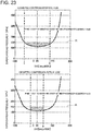
- the control part determines, according to the control logic, the close timing IVC (deg.aBDC) so that the supercharging pressure P (kPa) satisfies the following expression.
- P 8.0 ⁇ 10 ⁇ 11 IVC 6 ⁇ 1.0 ⁇ 10 ⁇ 8 IVC 5 + 3.0 ⁇ 10 ⁇ 7 IVC 4 ⁇ 4.0 ⁇ 10 ⁇ 6 IVC 3 + 0.0068 IVC 2 ⁇ 0.3209 IVC + 116.63
- the ignition part ignites the mixture gas inside the combustion chamber in response to the signal from the control part.
- the combustion starts by flame propagation and then the unburnt mixture gas combusts by self-ignition to complete the combustion. That is, this engine performs the SPCCI (SPark Controlled Compression Ignition) combustion.
- SPCCI Park Controlled Compression Ignition
- the G/F of the mixture gas is made leaner than the stoichiometric air fuel ratio and the A/F is made to be substantially the stoichiometric air fuel ratio or richer than the stoichiometric air fuel ratio.
- the G/F lean fuel efficiency of the engine improves, and by making the A/F substantially the stoichiometric air fuel ratio, emission performance improves by using a catalyst device.
- the boost by the supercharger results in keeping the G/F of the mixture gas leaner than the stoichiometric air fuel ratio. This is advantageous in improving the fuel efficiency of the engine.
- the control part When controlling the engine, the control part first determines the supercharging pressure P by the supercharger. When the supercharging pressure P is set, the control part determines the close timing IVC of the intake valve so that the expression (A) is satisfied. By setting the close timing so as to satisfy the expression (A), the engine can perform a stable SPCCI combustion which is a combination of SI (Spark Ignition) combustion and CI (Compression Ignition) combustion while keeping combustion noise within the allowable range and the G/F lean environment, even under various conditions with different situations of the combustion chamber.
- SI Spark Ignition
- CI Compression Ignition
- the index for determining the close timing IVC of the intake valve, which is available when controlling the engine for performing the SPCCI combustion, has been unknown until now.
- the controlling method defines the relationship between the supercharging pressure P and the close timing IVC of the intake valve in order to achieve a suitable SPCCI combustion.
- the control part can set the close timing IVC of the intake valve within the range in which the relationship is satisfied. Accordingly, the engine for performing the SPCCI combustion can put to practical use.
- the supercharging pressure (kPa) may be determined so as to satisfy the following expression. P ⁇ 150
- the control part may determine a target supercharging pressure corresponding to the operating state of the engine.
- the control part may determine the close timing IVC (deg.aBDC) so that, when the target supercharging pressure is used as the supercharging pressure P (kPa), the supercharging pressure P (kPa) satisfies the expression.
- the G/F of the mixture gas is leaner than the stoichiometric air fuel ratio and the A/F is substantially the stoichiometric air fuel ratio or richer than the stoichiometric air fuel ratio, which is advantageous in improving fuel efficiency.
- the close timing IVC of the intake valve may change as the operating state of the engine changes, and the close timing IVC (deg.aBDC) may be determined for each operating state so that one of the expressions (A) and (B) is satisfied.
- the engine can stably perform the SPCCI combustion in various operating states.
- the engine may operate in a high-load operating state at a given load or higher.
- the engine may operate in a maximum load operating state. That is the engine may perform the SPCCI combustion in the maximum load operating state.
- a geometric compression ratio ⁇ of the engine may be set so as to satisfy about 10 ⁇ about 21. In this way, the geometric compression ratio can be set suitably.
- the engine may be provided with an exhaust gas recirculation (EGR) system configured to introduce exhaust gas into the combustion chamber.
- EGR exhaust gas recirculation
- the control part may output the signal to the EGR system and the ignition part so that a heat amount ratio used as an index related to a ratio of an amount of heat generated when the mixture gas inside the combustion chamber combusts by flame propagation to the entire amount of heat generated when the mixture gas combusts, becomes a target heat amount ratio defined corresponding to the operating state of the engine.
- the heat amount ratio of the SPCCI combustion is less than about 100%.
- the heat amount ratio of the combustion mode where the combustion completes only by flame propagation without the combustion by compression ignition i.e., SI combustion is about 100%.
- the ratio of the SI combustion increases, which is advantageous in reducing combustion noise.
- the ratio of the CI combustion increases, which is advantageous in improving fuel efficiency.
- the heat amount ratio changes by changing the temperature of the combustion chamber and/or the ignition timing. For example, when the temperature inside the combustion chamber is high, the CI combustion starts at an early timing, and the heat amount ratio becomes low. Further, when the ignition timing is advanced, the SI combustion starts at an early timing, and the heat amount ratio becomes high.
- the control part may output a signal to the EGR system and the ignition part so that the heat amount ratio becomes higher when the load of the engine is higher.
- the invention relates to a computer program product comprising computer-readable instructions, which when loaded and executed on a suitable system, can perform the steps of any of the above-mentioned methods.
- a compression-ignition engine comprising a fuel injection part configured to inject fuel to be supplied in a combustion chamber; a variable valve operating mechanism configured to change a valve timing of an intake valve; an ignition part configured to ignite a mixture gas inside the combustion chamber; a supercharger configured to boost gas introduced into the combustion chamber; a measurement part configured to measure a parameter related to an operating state of the engine, and a control part configured to perform a calculation according to a control logic corresponding to the operating state of the engine, in response to the measurement of the measurement part, and output a signal to the fuel injection part, the variable valve operating mechanism, the ignition part, and the supercharger, the control part outputting the signal to the fuel injection part, the variable valve operating mechanism and the supercharger so that a gas-fuel ratio that is a weight ratio of the
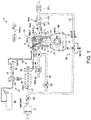
- Fig. 1 is a view illustrating a configuration of the compression-ignition engine.
- Fig. 2 is a view illustrating a configuration of a combustion chamber of the engine.
- Fig. 3 is a view illustrating a configuration of the combustion chamber and an intake system. Note that in Fig. 1 , an intake side is the left side in the drawing, and an exhaust side is the right side in the drawing. In Figs. 2 and 3 , the intake side is the right side in the drawings, and the exhaust side is the left side in the drawings.
- Fig. 4 is a block diagram illustrating a configuration of a control device for the engine.
- An engine 1 is a four-stroke engine which operates by a combustion chamber 17 repeating an intake stroke, a compression stroke, an expansion stroke, and an exhaust stroke.
- the engine 1 is mounted on an automobile with four wheels. The automobile travels by operating the engine 1.
- Fuel of the engine 1 is gasoline in this example.
- the fuel may be a liquid fuel containing at least gasoline.
- the fuel may be gasoline containing, for example, bioethanol.
- the engine 1 includes a cylinder block 12 and a cylinder head 13 placed thereon. A plurality of cylinders 11 are formed inside the cylinder block 12. In Figs. 1 and 2 , only one cylinder 11 is illustrated.
- the engine 1 is a multi-cylinder engine.
- a piston 3 is slidably inserted in each cylinder 11.
- the pistons 3 are connected with a crankshaft 15 through respective connecting rods 14.
- Each piston 3 defines the combustion chamber 17, together with the cylinder 11 and the cylinder head 13.
- combustion chamber may be used in a broad sense. That is, the term “combustion chamber” may refer to a space formed by the piston 3, the cylinder 11, and the cylinder head 13, regardless of the position of the piston 3.
- a lower surface of the cylinder head 13, i.e., a ceiling surface of the combustion chamber 17, is comprised of a slope 1311 and a slope 1312.
- the slope 1311 is a rising gradient from the intake side toward an injection axial center X2 of an injector 6 which will be described later.
- the slope 1312 is a rising gradient from the exhaust side toward the injection axial center X2.
- the ceiling surface of the combustion chamber 17 is a so-called "pent-roof" shape.
- An upper surface of the piston 3 is bulged toward the ceiling surface of the combustion chamber 17.
- a cavity 31 is formed in the upper surface of the piston 3.
- the cavity 31 is a dent in the upper surface of the piston 3.
- the cavity 31 has a shallow pan shape in this example.
- the center of the cavity 31 is offset at the exhaust side with respect to a center axis X1 of the cylinder 11.
- a geometric compression ratio ⁇ of the engine 1 is set so as to satisfy about 10 ⁇ about 30, and preferably satisfy 10 ⁇ 21.
- the engine 1 which will be described later performs SPCCI (SPark Controlled Compression Ignition) combustion that is a combination of SI (Spark Ignition) combustion and CI (Compression Ignition) combustion in a part of operating ranges.
- the SPCCI combustion controls the CI combustion using a heat generation and a pressure buildup by the SI combustion.
- the engine 1 is the compression-ignition engine. However, in this engine 1, temperature of the combustion chamber 17, when the piston 3 is at a compression top dead center (i.e., compression end temperature), does not need to be increased. In the engine 1, the geometric compression ratio can be set comparatively low.
- the low geometric compression ratio becomes advantageous in reduction of cooling loss and mechanical loss.
- the geometric compression ratio of the engine 1 is about 14-about 17, and for those using high octane gasoline (high octane fuel of which octane number is about 96), the geometric compression ratio is about 15-about 18.
- An intake port 18 is formed in the cylinder head 13 for each cylinder 11. As illustrated in Fig. 3 , each intake port 18 has a first intake port 181 and a second intake port 182. The intake port 18 communicates with the corresponding combustion chamber 17. Although the detailed illustration of the intake port 18 is omitted, it is a so-called "tumble port.” That is, the intake port 18 has such a shape that a tumble flow is formed in the combustion chamber 17.
- Each intake valve 21 is disposed in the intake ports 181 and 182.
- the intake valve 21 opens and closes a channel between the combustion chamber 17 and the intake port 181 or 182.
- the intake valves 21 are opened and closed at given timings by a valve operating mechanism.
- the valve operating mechanism may be a variable valve operating mechanism which varies the valve timing and/or valve lift.
- the variable valve operating mechanism has an intake-side electric S-VT (Sequential-Valve Timing) 23.
- the intake-side electric S-VT 23 continuously varies a rotation phase of an intake cam shaft within a given angle range.
- the open timing and the close timing of the intake valve 21 vary continuously.
- the electric S-VT may be replaced with a hydraulic S-VT, as the intake valve operating mechanism.
- each exhaust port 19 is also formed in the cylinder head 13 for each cylinder 11. As illustrated in Fig. 3 , each exhaust port 19 also has a first exhaust port 191 and a second exhaust port 192. The exhaust port 19 communicates with the corresponding combustion chamber 17.
- Each exhaust valve 22 is disposed in the exhaust ports 191 and 192.
- the exhaust valve 22 opens and closes a channel between the combustion chamber 17 and the exhaust port 191 or 192.
- the exhaust valves 22 are opened and closed at a given timing by a valve operating mechanism.
- the valve operating mechanism may be a variable valve operating mechanism which varies the valve timing and/or valve lift.
- the variable valve operating mechanism has an exhaust-side electric SVT 24.
- the exhaust-side electric S-VT 24 continuously varies a rotation phase of an exhaust cam shaft within a given angle range.
- the open timing and the close timing of the exhaust valve 22 change continuously.
- the electric S-VT may be replaced with a hydraulic S-VT, as the exhaust valve operating mechanism.
- the intake-side electric S-VT 23 and the exhaust-side electric S-VT 24 adjust the length of an overlap period where both the intake valve 21 and the exhaust valve 22 are open. If the length of the overlap period is made longer, the residual gas in the combustion chamber 17 can be purged. Moreover, by adjusting the length of the overlap period, internal EGR (Exhaust Gas Recirculation) gas can be introduced into the combustion chamber 17.
- An internal EGR system is comprised of the intake-side electric S-VT 23 and the exhaust-side electric S-VT 24. Note that the internal EGR system may not be comprised of the S-VT.
- the injector 6 is attached to the cylinder head 13 for each cylinder 11. Each injector 6 directly injects fuel into the combustion chamber 17.
- the injector 6 is one example of a fuel injection part.
- the injector 6 is disposed in a valley part of the pent roof where the slope 1311 and the slope 1312 meet.
- the injection axial center X2 of the injector 6 is located at the exhaust side of the center axis X1 of the cylinder 11.
- the injection axial center X2 of the injector 6 is parallel to the center axis X1.
- the injection axial center X2 of the injector 6 and the center of the cavity 31 are in agreement with each other.
- the injector 6 faces the cavity 31.
- injection axial center X2 of the injector 6 may be in agreement with the center axis X1 of the cylinder 11.
- the injection axial center X2 of the injector 6 and the center of the cavity 31 may be in agreement with each other.
- the injector 6 is comprised of a multi nozzle-port type fuel injection valve having a plurality of nozzle ports. As illustrated by two-dot chain lines in Fig. 2 , the injector 6 injects fuel so that the fuel spreads radially from the center of the combustion chamber 17.
- the injector 6 has ten nozzle ports in this example, and the nozzle port is disposed so as to be equally spaced in the circumferential direction.
- the injectors 6 are connected to a fuel supply system 61.
- the fuel supply system 61 includes a fuel tank 63 configured to store fuel, and a fuel supply passage 62 which connects the fuel tank 63 to the injector 6.
- a fuel pump 65 and a common rail 64 are provided in the fuel supply passage 62.
- the fuel pump 65 pumps fuel to the common rail 64.
- the fuel pump 65 is a plunger pump driven by the crankshaft 15 in this example.
- the common rail 64 stores fuel pumped from the fuel pump 65 at a high fuel pressure.
- the fuel supply system 61 can supply fuel to the injectors 6 at a high pressure of about 30 MPa or higher.
- the pressure of fuel supplied to the injector 6 may be changed according to the operating state of the engine 1. Note that the configuration of the fuel supply system 61 is not limited to the configuration described above.
- An ignition plug 25 is attached to the cylinder head 13 for each cylinder 11.
- the ignition plug 25 forcibly ignites a mixture gas inside the combustion chamber 17.
- the ignition plug 25 is disposed at the intake side of the center axis X1 of the cylinder 11 in this example.
- the ignition plug 25 is located between the two intake ports 181 and 182 of each cylinder.
- the ignition plug 25 is attached to the cylinder head 13 so as to incline downwardly toward the center of the combustion chamber 17.
- the electrode of the ignition plug 25 faces to the inside of the combustion chamber 17 and is located near the ceiling surface of the combustion chamber 17.
- the ignition plug 25 may be disposed at the exhaust side of the center axis X1 of the cylinder 11.
- the ignition plug 25 may be disposed on the center axis X1 of the cylinder 11.
- An intake passage 40 is connected to one side surface of the engine 1.
- the intake passage 40 communicates with the intake port 18 of each cylinder 11.
- Gas introduced into the combustion chamber 17 flows through the intake passage 40.
- An air cleaner 41 is disposed in an upstream end part of the intake passage 40.
- the air cleaner 41 filters fresh air.
- a surge tank 42 is disposed near the downstream end of the intake passage 40. Part of the intake passage 40 downstream of the surge tank 42 constitutes independent passages branched from the intake passage 40 for each cylinder 11. The downstream end of each independent passage is connected to the intake port 18 of each cylinder 11.
- a throttle valve 43 is disposed between the air cleaner 41 and the surge tank 42 in the intake passage 40.
- the throttle valve 43 adjusts an introducing amount of the fresh air into the combustion chamber 17 by adjusting an opening of the throttle valve.
- a supercharger 44 is also disposed in the intake passage 40, downstream of the throttle valve 43.
- the supercharger 44 boosts gas to be introduced into the combustion chamber 17.
- the supercharger 44 is a mechanical supercharger driven by the engine 1.
- the mechanical supercharger 44 may be a root, Lysholm, vane, or a centrifugal type.
- An electromagnetic clutch 45 is provided between the supercharger 44 and the engine 1.
- the electromagnetic clutch 45 transmits a driving force from the engine 1 to the supercharger 44 or disengages the transmission of the driving force between the supercharger 44 and the engine 1.
- an ECU 10 switches the disengagement and engagement of the electromagnetic clutch 45 to switch the supercharger 44 between ON and OFF.
- An intercooler 46 is disposed downstream of the supercharger 44 in the intake passage 40.
- the intercooler 46 cools gas compressed by the supercharger 44.
- the intercooler 46 may be of a water cooling type or an oil cooling type, for example.
- a bypass passage 47 is connected to the intake passage 40.
- the bypass passage 47 connects an upstream part of the supercharger 44 to a downstream part of the inter cooler 46 in the intake passage 40 so as to bypass the supercharger 44 and the inter cooler 46.
- An air bypass valve 48 is disposed in the bypass passage 47. The air bypass valve 48 adjusts a flow rate of gas flowing in the bypass passage 47.
- the ECU 10 substantially fully opens the air bypass valve 48 when the supercharger 44 is turned OFF (i.e., when the electromagnetic clutch 45 is disengaged).
- the gas flowing through the intake passage 40 bypasses the supercharger 44 and is introduced into the combustion chamber 17 of the engine 1.
- the engine 1 operates in a non-supercharged state, i.e., a natural aspiration state.
- the engine 1 When the supercharger 44 is turned ON, the engine 1 operates in a supercharged state.
- the ECU 10 adjusts an opening of the air bypass valve 48 when the supercharger 44 is turned ON (i.e., when the electromagnetic clutch 45 is engaged). A portion of the gas which passed through the supercharger 44 flows back toward upstream of the supercharger 44 through the bypass passage 47.
- the ECU 10 adjusts the opening of the air bypass valve 48, a supercharging pressure of gas introduced into the combustion chamber 17 changes.
- supercharging refers to a situation where the pressure inside the surge tank 42 exceeds an atmospheric pressure
- non-supercharging refers to a situation where the pressure inside the surge tank 42 becomes below the atmospheric pressure.
- a supercharging system 49 is comprised of the supercharger 44, the bypass passage 47, and the air bypass valve 48.
- the engine 1 has a swirl generating part which generates a swirl flow inside the combustion chamber 17.
- the swirl generating part has a swirl control valve 56 attached to the intake passage 40.
- the swirl control valve 56 is disposed in the secondary passage 402.
- the swirl control valve 56 is an opening control valve which is configured to choke a cross section of the secondary passage 402.
- An exhaust passage 50 is connected to the other side surface of the engine 1.
- the exhaust passage 50 communicates with the exhaust port 19 of each cylinder 11.
- the exhaust passage 50 is a passage through which exhaust gas discharged from the combustion chambers 17 flows.
- an upstream part of the exhaust passage 50 constitutes independent passages branched from the exhaust passage 50 for each cylinder 11.
- the upper end of the independent passage is connected to the exhaust port 19 of each cylinder 11.
- An exhaust gas purification system having a plurality of catalytic converters is disposed in the exhaust passage 50.
- an upstream catalytic converter is disposed inside an engine room.
- the upstream catalytic converter has a three-way catalyst 511 and a GPF (Gasoline Particulate Filter) 512.
- the downstream catalytic converter is disposed outside the engine room.
- the downstream catalytic converter has a three-way catalyst 513.
- the exhaust gas purification system is not limited to the illustrated configuration.
- the GPF may be omitted.
- the catalytic converter is not limited to those having the three-way catalyst. Further, the order of the three-way catalyst and the GPF may suitably be changed.
- an EGR passage 52 which constitutes an external EGR system is connected.
- the EGR passage 52 is a passage for recirculating part of the exhaust gas to the intake passage 40.
- the upstream end of the EGR passage 52 is connected between the upstream catalytic converter and the downstream catalytic converter in the exhaust passage 50.
- the downstream end of the EGR passage 52 is connected to an upstream part of the supercharger 44 in the intake passage 40. EGR gas flowing through the EGR passage 52 flows into the upstream part of the supercharger 44 in the intake passage 40, without passing through the air bypass valve 48 of the bypass passage 47.
- An EGR cooler 53 of a water cooling type is disposed in the EGR passage 52.
- the EGR cooler 53 cools the exhaust gas.
- An EGR valve 54 is also disposed in the EGR passage 52.
- the EGR valve 54 adjusts a flow rate of the exhaust gas flowing through the EGR passage 52. By adjusting the opening of the EGR valve 54, an amount of the cooled exhaust gas, i.e., a recirculating amount of external EGR gas can be adjusted.
- an EGR system 55 is comprised of the external EGR system and the internal EGR system.
- the external EGR system can supply the exhaust gas to the combustion chamber 17 that is lower in temperature than the internal EGR system.
- the control device of the compression-ignition engine includes the ECU (Engine Control Unit) 10 for operating the engine 1.
- the ECU 10 is a controller based on a well-known microcomputer, and as illustrated in Fig. 4 , includes a central processing unit (CPU) 101 which executes a computer program, memory 102 which, for example, is comprised of a RAM (Random Access Memory) and/or a ROM (Read Only Memory), and stores the program and data, and an input/output bus 103 which inputs and outputs an electrical signal.
- the ECU 10 is one example of the control part.
- sensors SW1-SW17 are connected to the ECU 10.
- the sensors SW1-SW17 output signals to the ECU 10.
- the sensors include the following sensors:
- the ECU 10 determines the operating state of the engine 1 based on the signals of the sensors SW1-SW17, and calculates a control amount of each device according to the control logic defined beforehand.
- the control logic is stored in the memory 102.
- the control logic includes calculating a target amount and/or the control amount by using a map stored in the memory 102.
- the ECU 10 outputs electrical signals according to the calculated control amounts to the injectors 6, the ignition plugs 25, the intake-side electric S-VT 23, the exhaust-side electric S-VT 24, the fuel supply system 61, the throttle valve 43, the EGR valve 54, the electromagnetic clutch 45 of the supercharger 44, the air bypass valve 48, and the swirl control valve 56.
- the ECU 10 sets a target torque of the engine 1 based on the signal of the accelerator opening sensor SW12 and the map, and determines a target supercharging pressure.
- the ECU 10 then performs a feedback control for adjusting the opening of the air bypass valve 48 based on the target supercharging pressure and the pressure difference before and after the supercharger 44 obtained from the signals of the first pressure sensor SW3 and the second pressure sensor SW5 so that the supercharging pressure becomes the target supercharging pressure.
- the ECU 10 sets a target EGR ratio (i.e., a ratio of the EGR gas to the entire gas inside the combustion chamber 17) based on the operating state of the engine 1 and the map.
- the ECU 10 determines a target EGR gas amount based on the target EGR ratio and an intake air amount based on the signal of the accelerator opening sensor SW12, and performs a feedback control for adjusting the opening of the EGR valve 54 based on the pressure difference before and after the EGR valve 54 obtained from the signal of the EGR pressure difference sensor SW15 so that the external EGR gas amount introduced into the combustion chamber 17 becomes the target EGR gas amount.
- the ECU 10 performs an air-fuel ratio feedback control when a given control condition is satisfied. For example, the ECU 10 adjusts the fuel injection amount of the injector 6 based on the oxygen concentration of the exhaust gas which is measured by the linear O 2 sensor SW8 and the lambda O 2 sensor SW9 so that the air-fuel ratio of the mixture gas becomes a desired value.
- the engine 1 performs combustion by compressed self-ignition under a given operating state, mainly to improve fuel consumption and emission performance.
- the combustion by self-ignition varies largely at the timing of the self-ignition, if the temperature inside the combustion chamber 17 before a compression starts is nonuniform.
- the engine 1 performs the SPCCI combustion which is a combination of the SI combustion and the CI combustion.
- the SPCCI combustion is combustion in which the ignition plug 25 forcibly ignites the mixture gas inside the combustion chamber 17 so that the mixture gas carries out the SI combustion by flame propagation, and the temperature inside the combustion chamber 17 increases by the heat generation of the SI combustion and the pressure inside the combustion chamber 17 increases by the flame propagation so that the unburnt mixture gas carries out the CI combustion by self-ignition.
- the mixture gas can be self-ignited at a target timing.
- the heat release of the SI combustion is slower than the heat release in the CI combustion.
- the waveform of the heat release rate of the SI combustion in the SPCCI combustion is smaller in the rising slope than the waveform in the CI combustion.
- the SI combustion is slower in the pressure fluctuation (dp/d ⁇ ) inside the combustion chamber 17 than the CI combustion.
- the waveform slope of the heat release rate may become steeper.
- the waveform of the heat release rate may have an inflection point X at a timing of starting the CI combustion.
- the SI combustion and the CI combustion are performed in parallel. Since the CI combustion has larger heat release than the SI combustion, the heat release rate becomes relatively large. However, since the CI combustion is performed after a compression top dead center, the waveform slope of the heat release rate does not become too steep. The pressure fluctuation in the CI combustion (dp/d ⁇ ) also becomes comparatively slow.
- the pressure fluctuation (dp/d ⁇ ) can be used as an index representing combustion noise. As described above, since the SPCCI combustion can reduce the pressure fluctuation (dp/d ⁇ ), it is possible to avoid excessive combustion noise. Combustion noise of the engine 1 can be kept below the tolerable level.
- the SPCCI combustion is completed when the CI combustion is finished.
- the CI combustion is shorter in the combustion period than the SI combustion.
- the end timing of the SPCCI combustion becomes earlier than the SI combustion.
- the heat release rate waveform of the SPCCI combustion is formed so that a first heat release rate part Q SI formed by the SI combustion and a second heat release rate part Q CI formed by the CI combustion continue in this order.
- a SI ratio is defined as a parameter indicative of a characteristic of the SPCCI combustion.
- the SI ratio is defined as an index related to a ratio of the amount of heat generated by the SI combustion to the entire amount of heat generated by the SPCCI combustion.
- the SI ratio is a ratio of heat amount generated by the two different combustion modes. If the SI ratio is high, the ratio of the SI combustion is high, and if the SI ratio is low, the ratio in the CI combustion is high.
- the engine 1 generates a strong swirl flow inside the combustion chamber 17 when performing the SPCCI combustion.
- strong swirl flow may be defined as a flow having a swirl ratio of about four or higher, for example.
- the swirl ratio can be defined as a value obtained by dividing an integrated value of intake flow lateral angular velocities by an engine angular velocity, where the intake flow lateral angular velocity is measured for every valve lift, and the measured values are integrated to obtain the integrated value.
- the intake flow lateral angular velocity can be obtained based on measurement using known rig test equipment.
- Flame of the SI combustion is carried by the strong swirl flow inside the combustion chamber 17 and propagates in the circumferential direction.
- the CI combustion is performed from the outer circumferential part to the central part in the combustion chamber 17.
- the SI combustion can fully be performed before the start in the CI combustion.
- the generation of combustion noise can be reduced, and the variation in the torque between cycles can be reduced.
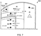
- Figs. 6 and 7 illustrate maps according to the control of the engine 1.
- the maps are stored in the memory 102 of the ECU 10.
- the maps include three kinds of maps, a map 501, a map 502, and a map 503.
- the ECU 10 uses a map selected from the three kinds of maps 501, 502, and 503 according to a wall temperature of the combustion chamber 17 and an intake air temperature, in order to control the engine 1. Note that the details of the selection of the three kinds of maps 501, 502, and 503 will be described later.
- the first map 501 is a map when the engine 1 is warm.
- the second map 502 is a map when the engine 1 is half warm.
- the third map 503 is a map when the engine 1 is cold.
- the maps 501, 502, and 503 are defined based on the load and the engine speed of the engine 1.
- the first map 501 is roughly divided into three areas depending on the load and the engine speed.
- the three areas include a low load area A1, a middle-to-high load area (A2, A3, and A4), and a high speed area A5.
- the low load area A1 includes idle operation, and covers areas of a low engine speed and a middle engine speed.
- the middle-to-high load area (A2, A3, and A4) are higher in the load than the low load area A1.
- the high speed area A5 is higher in the engine speed than the low load area A1 and the middle-to-high load area (A2, A3, and A4).
- the middle-to-high load area (A2, A3, and A4) is divided into a middle load area A2, a high-load middle-speed area A3 where the load is higher than the middle load area A2, and a high-load low-speed area A4 where the engine speed is lower than the high-load middle-speed area A3.
- the second map 502 is roughly divided into two areas.
- the two areas include a low-to-middle speed area (B1, B2, and B3) and a high speed area B4 where the engine speed is higher than the low-to-middle speed area (B1, B2, and B3).
- the low-to-middle speed area (B1, B2, and B3) is divided into a low-to-middle load area B1 corresponding to the low load area A1 and the middle load area A2, a high-load middle-speed area B2, and a high-load low-speed area B3.
- the third map 503 has only one area C1, without being divided into a plurality of areas.
- the low speed area, the middle speed area, and the high speed area may be defined by substantially equally dividing the entire operating range of the engine 1 into three areas in the engine speed direction.
- the engine speed is defined to be a low speed if the engine speed is lower than the engine speed N1, a high speed if the engine speed is higher than or equal to the engine speed N2, and a middle speed if the engine speed is higher than or equal to the engine speed N1 and lower than the engine speed N2.
- the engine speed N1 may be about 1,200 rpm
- the engine speed N2 may be about 4,000 rpm.
- the low load area may be an area including an operating state with the light load
- the high load area may be an area including an operating state with full load
- the middle load area may be an area between the low load area and the high load area.
- the low load area, the middle load area, and the high load area may be defined by substantially equally dividing the entire operating range of the engine 1 into three areas in the load direction.
- the maps 501, 502, and 503 in Fig. 6 illustrate the states and combustion modes of the mixture gas in the respective areas.
- a map 504 in Fig. 7 corresponds to the first map 501, and illustrates the state and combustion mode of the mixture gas in each area of the map, the opening of the swirl control valve 56 in each area, and a driving area and a non-driving area of the supercharger 44.
- the engine 1 performs the SPCCI combustion in the low load area A1, the middle load area A2, the high-load middle-speed area A3, the high-load low-speed area A4, the low-to-middle load area B1, the high-load middle-speed area B2, and the high-load low-speed area B3.
- the engine 1 performs the SI combustion in other areas, specifically, in the high speed area A5, the high speed area B4, and the area C1.
- Fig. 8 The horizontal axis in Fig. 8 is a crank angle. Note that the reference numerals 601, 602, 603, 604, 605, and 606 in Fig. 8 correspond to the operating states of the engine 1 indicated by the reference numerals 601, 602, 603, 604, 605, and 606 in the map 504 of Fig. 7 , respectively.
- the engine 1 performs the SPCCI combustion when the engine 1 operates in the low load area A1.
- the reference numeral 601 in Fig. 8 indicates fuel injection timings (reference numerals 6011 and 6012), an ignition timing (reference numeral 6013), and a combustion waveform (i.e., a waveform indicating a change in the heat release rate with respect to the crank angle: reference numeral 6014), when the engine 1 operates in the operating state 601 in the low load area A1.
- the reference numeral 602 indicates fuel injection timings (reference numerals 6021 and 6022), an ignition timing (reference numeral 6023), and a combustion waveform (reference numeral 6024), when the engine 1 operates in the operating state 602 in the low load area A1.
- the reference numeral 603 indicates fuel injection timings (reference numerals 6031 and 6032), an ignition timing (reference numeral 6033), and a combustion waveform (reference numeral 6034), when the engine 1 operates in the operating state 603 in the low load area A1.
- the operating states 601, 602, and 603 have the same engine speed, but different loads.
- the operating state 601 has the lowest load (i.e., light load)
- the operating state 602 has the second lowest load (i.e., low load)
- the operating state 603 has the maximum load among these states.
- the EGR system 55 introduces the EGR gas into the combustion chamber 17.
- the intake-side electric S-VT 23 and the exhaust-side electric S-VT 24 are provided with a positive overlap period where both the intake valve 21 and the exhaust valve 22 are opened near an exhaust top dead center. Part of the exhaust gas discharged from the combustion chamber 17 into the intake port 18 and the exhaust port 19 is re-introduced into the combustion chamber 17. Since the hot exhaust gas is introduced into the combustion chamber 17, the temperature inside the combustion chamber 17 increases. Thus, it becomes advantageous to stabilize the SPCCI combustion.
- the intake-side electric S-VT 23 and the exhaust-side electric S-VT 24 may be provided with a negative overlap period where both the intake valve 21 and the exhaust valve 22 are closed.
- the swirl generating part forms the strong swirl flow inside the combustion chamber 17.
- the swirl ratio is about four or higher, for example.
- the swirl control valve 56 is fully closed or at a given opening (closed to some extent). As described above, since the intake port 18 is the tumble port, an inclined swirl flow having a tumble component and a swirl component is formed in the combustion chamber 17.
- the injector 6 injects fuel into the combustion chamber 17 a plurality of times during the intake stroke (reference numerals 6011, 6012, 6021, 6022, 6031, and 6032).
- the mixture gas is stratified by the multiple fuel injections and the swirl flow inside the combustion chamber 17.
- the fuel concentration of the mixture gas in the central part of the combustion chamber 17 is denser or richer than the fuel concentration in the outer circumferential part.
- the air-fuel ratio (A/F) of the mixture gas in the central part is about 20 or higher and about 30 or lower, and the A/F of the mixture gas in the outer circumferential part is about 35 or higher.
- the value of the A/F is a value when the mixture gas is ignited, and the same applies to the following description. Since the A/F of the mixture gas near the ignition plug 25 is set to about 20 or higher and about 30 or lower, generation of raw NO x during the SI combustion can be reduced. Moreover, since the A/F of the mixture gas in the outer circumferential part is set to about 35 or higher, the CI combustion stabilizes.
- the A/F of the mixture gas is leaner than the stoichiometric air fuel ratio throughout the combustion chamber 17 (i.e., excess air ratio ⁇ >1).
- the A/F of the mixture gas is about 30 or higher throughout the combustion chamber 17.
- the injector 6 When the engine load is low (i.e., in the operating state 601), the injector 6 performs the first injection 6011 in the first half of an intake stroke, and performs the second injection 6012 in the second half of the intake stroke.
- the first half of the intake stroke may be a first half of an intake stroke when the intake stroke is substantially equally divided into two, and the second half of the intake stroke may be the rest.
- an injection amount ratio of the first injection 6011 to the second injection 6012 may be about 9:1, for example.
- the injector 6 initiates the second injection 6022 which is performed in the second half of an intake stroke at a timing advanced from the second injection 6012 in the operating state 601.
- the injection amount ratio of the first injection 6021 to the second injection 6022 may be about 7:3 to about 8:2, for example.
- the injector 6 initiates the second injection 6032 which is performed in the second half of an intake stroke at a timing further advanced from the second injection 6022 in the operating state 602.
- the injection amount ratio of the first injection 6031 to the second injection 6032 may be about 6:4, for example.
- the ignition plug 25 ignites the mixture gas in the central part of the combustion chamber 17 at a given timing before a compression top dead center (reference numerals 6013, 6023, and 6033).
- the ignition timing may be during a final stage of the compression stroke.
- the compression stroke may be substantially equally divided into three, an initial stage, a middle stage, and a final stage, and this finale stage may be used as the final stage of the compression stroke described above.
- the mixture gas in the central part has the relatively high fuel concentration, the ignitability improves and the SI combustion by flame propagation stabilizes.
- the CI combustion begins at a suitable timing.
- the controllability in the CI combustion improves in the SPCCI combustion.
- the generation of combustion noise is reduced.
- the A/F of the mixture gas is made leaner than the stoichiometric air fuel ratio to perform the SPCCI combustion, fuel efficiency of the engine 1 can be significantly improved.
- the low load area A1 corresponds to Layer 3 described later. Layer 3 extends to the light load operating range and includes a minimum load operating state.
- the engine 1 When the engine 1 operates in the middle-to-high load area, the engine 1 also performs the SPCCI combustion, similar to the low load area.
- the reference numeral 604 in Fig. 8 indicates, in the middle-to-high load area, fuel injection timings (reference numerals 6041 and 6042), an ignition timing (reference numeral 6043), and a combustion waveform (reference numeral 6044), when the engine 1 operates in the operating state 604 in the middle load area A2.
- the reference numeral 605 indicates a fuel injection timing (reference numeral 6051), an ignition timing (reference numeral 6052), and a combustion waveform (reference numeral 6053), when the engine 1 operates in the operating state 605 in the high-load low-speed area A4.
- the EGR system 55 introduces the EGR gas into the combustion chamber 17.
- the intake-side electric S-VT 23 and the exhaust-side electric S-VT 24 are provided with a positive overlap period where both the intake valve 21 and the exhaust valve 22 are opened near an exhaust top dead center.
- Internal EGR gas is introduced into the combustion chamber 17.
- the EGR system 55 introduces the exhaust gas cooled by the EGR cooler 53 into the combustion chamber 17 through the EGR passage 52. That is, the external EGR gas with a lower temperature than the internal EGR gas is introduced into the combustion chamber 17.
- the external EGR gas adjusts the temperature inside the combustion chamber 17 to a suitable temperature.
- the EGR system 55 reduces the amount of the EGR gas as the engine load increases.
- the EGR system 55 may not recirculate the EGR gas containing the internal EGR gas and the external EGR gas during the full load.
- the swirl control valve 56 is fully closed or at a given opening (closed to some extent). In the combustion chamber 17, the strong swirl flow with the swirl ratio of four or higher is formed. On the other hand, in the high-load low-speed area A4, the swirl control valve 56 is open.
- the air-fuel ratio (A/F) of the mixture gas is about the stoichiometric air fuel ratio (A/F ⁇ 14.7:1) throughout the combustion chamber 17. Since the three-way catalysts 511 and 513 purify the exhaust gas discharged from the combustion chamber 17, the emission performance of the engine 1 is improved.
- the A/F of the mixture gas may be set within a purification window of the three-way catalyst.
- the excess air ratio ⁇ of the mixture gas may be about 1.0 ⁇ about 0.2.
- the A/F of the mixture gas may be set substantially at the stoichiometric air fuel ratio or richer than the stoichiometric air fuel ratio (i.e., the excess air ratio ⁇ of the mixture gas is ⁇ 1) throughout the combustion chamber 17.
- the G/F which is a weight ratio of the entire gas to the fuel in the combustion chamber 17 becomes leaner than the stoichiometric air fuel ratio.
- the G/F of the mixture gas may be about 18:1 or higher. Thus, a generation of a so-called "knock" is avoided.
- the G/F may be set to about 18:1 or higher and about 30:1 or lower. Alternatively, the G/F may be set to about 18:1 or higher and about 50:1 or lower.
- the injector 6 When the engine 1 operates in the operating state 604, the injector 6 performs a plurality of fuel injections (reference numerals 6041 and 6042) during an intake stroke.
- the injector 6 may perform the first injection 6041 in the first half of the intake stroke and the second injection 6042 in the second half of the intake stroke.
- the injector 6 injects fuel in an intake stroke (reference numeral 6051).
- the ignition plug 25 ignites the mixture gas at a given timing near a compression top dead center after the fuel is injected (reference numerals 6043 and 6052).
- the ignition plug 25 may ignite the mixture gas before the compression top dead center when the engine 1 operates in the operating state 604 (reference numeral 6043).
- the ignition plug 25 may ignite the mixture gas after the compression top dead center when the engine 1 operates in the operating state 605 (reference numeral 6052).
- the exhaust gas discharged from the combustion chamber 17 can be purified using the three-way catalysts 511 and 513. Moreover, the fuel efficiency of the engine 1 improves by introducing the EGR gas into the combustion chamber 17 and making the mixture gas leaner.
- the middle-to-high load areas A2, A3, and A4 correspond to Layer 2 described later. Layer 2 extends to the high load area and includes the maximum load operating state.
- the supercharger 44 is OFF in part of the low load area A1 and part of the middle load area A2 (see S/C OFF).
- the supercharger 44 is OFF in an area on the lower engine speed side in the low load area A1.
- the supercharger 44 is ON in order to secure a required intake filling amount for the increased speed of the engine 1.
- the supercharger 44 is OFF in a partial area on the lower load and lower engine speed side in the middle load area A2.
- the supercharger 44 is ON in order to secure a required intake filling amount for the increased fuel injection amount.
- the supercharger 44 is ON also in the area on the higher speed side in the middle load area A2.
- the supercharger 44 is entirely ON (see S/C ON).
- the engine 1 performs not the SPCCI combustion but the SI combustion when the engine 1 operates in the high speed area A5.
- the high speed area A5 extends entirely in the load direction from the low load to the high load.
- the reference numeral 606 of Fig. 8 indicates a fuel injection timing (reference numeral 6061), an ignition timing (reference numeral 6062), and a combustion waveform (reference numeral 6063), when the engine 1 operates in the high speed area A5 in the operating state 606 where the load is high.
- the EGR system 55 introduces the EGR gas into the combustion chamber 17.
- the EGR system 55 reduces the amount of the EGR gas as the load increases.
- the EGR system 55 may not recirculate the EGR gas during full load.
- the swirl control valve 56 is substantially fully opened. No swirl flow occurs in the combustion chamber 17, but only a tumble flow occurs. By substantially fully opening the swirl control valve 56, it is possible to increase the filling efficiency, and reduce the pumping loss.
- the air-fuel ratio (A/F) of the mixture gas is substantially the stoichiometric air fuel ratio (A/F ⁇ 14.7:1) throughout the combustion chamber 17.
- the excess air ratio ⁇ of the mixture gas may be set to about 1.0 ⁇ about 0.2. Note that the excess air ratio ⁇ of the mixture gas may be lower than about 1 when the engine 1 operates near full load.
- the injector 6 starts the fuel injection during an intake stroke.
- the injector 6 injects the fuel all at once (reference numeral 6061).
- the homogeneous or substantially homogeneous mixture gas is formed inside the combustion chamber 17. Moreover, since a longer vaporizing time of the fuel can be secured, unburnt fuel loss can also be reduced.
- the ignition plug 25 ignites the mixture gas at a suitable timing before a compression top dead center (reference numeral 6062).
- the maps 501, 502, and 503 of the engine 1 illustrated in Fig. 6 are comprised of a combination of three layers, Layer 1, Layer 2, and Layer 3.
- Layer 1 is a layer used as a base layer. Layer 1 extends throughout the operating range of the engine 1. Layer 1 corresponds to the entire third map 503.
- Layer 2 is a layer which is superimposed on Layer 1.
- Layer 2 corresponds to part of the operating range of the engine 1.
- Layer 2 corresponds to the low-to-middle speed area B1, B2, and B3 of the second map 502.
- Layer 3 is a layer which is superimposed on Layer 2. Layer 3 corresponds to the low load area A1 of the first map 501.
- Layer 1, Layer 2, and Layer 3 are selected according to the wall temperature of the combustion chamber 17 and the intake air temperature.
- the wall temperature of the combustion chamber 17 is higher than a given first wall temperature (e.g., about 80 °C) and the intake air temperature is higher than a given first intake air temperature (e.g., about 50 °C)
- a given first intake air temperature e.g., about 50 °C
- Layer 1, Layer 2, and Layer 3 are selected, and the first map 501 is formed by piling up Layer 1, Layer 2, and Layer 3.
- the top Layer 3 therein becomes effective, in the middle-to-high load areas A2, A3, and A4, the top Layer 2 therein becomes effective, and in the high speed area A5, Layer 1 becomes effective.
- Layer 1 and Layer 2 are selected.
- the second map 502 is formed.
- the wall temperature of the combustion chamber 17 may be replaced, for example, by temperature of the coolant of the engine 1 measured by the water temperature sensor SW10. Alternatively, the wall temperature of the combustion chamber 17 may be estimated based on the temperature of the coolant, or other measurements.
- the intake air temperature is measurable, for example, by the third intake-air temperature sensor SW17 which measures the temperature inside the surge tank 42. Alternatively, the temperature of the intake air introduced into the combustion chamber 17 may be estimated based on various kinds of measurements.
- the SPCCI combustion is performed by generating the strong swirl flow inside the combustion chamber 17. Since the flame propagates along the wall of the combustion chamber 17 during the SI combustion, the flame propagation of the SI combustion is influenced by the wall temperature. If the wall temperature is low, the flame of the SI combustion is cooled to delay the timing of compression-ignition.
- the CI combustion of the SPCCI combustion is performed in the area from the outer circumferential part to the central part of the combustion chamber 17, it is influenced by the temperature in the central part of the combustion chamber 17. If the temperature in the central part is low, the CI combustion becomes unstable.
- the temperature in the central part of the combustion chamber 17 depends on the temperature of the intake air introduced into the combustion chamber 17. That is, when the intake air temperature is higher, the temperature in the central part of the combustion chamber 17 becomes higher, and when the intake air temperature is lower, the temperature in the central part becomes lower.
- the stable SPCCI combustion of the mixture gas having substantially stoichiometric air fuel ratio (i.e., ⁇ 1) can be carried out.
- Layer 2 is selected, and the ECU 10 operates the engine 1 based on the second map 502.
- the stable SPCCI combustion of the mixture gas leaner than the stoichiometric air fuel ratio can be carried out.
- Layer 3 is selected, and the ECU 10 operates the engine 1 based on the first map 501.
- Step S1 the ECU 10 reads the signals of the sensors SW1-SW17.
- Step S2 the ECU 10 determines whether the wall temperature of the combustion chamber 17 is about 30 °C or higher and the intake air temperature is about 25 °C or higher. If the determination at Step S2 is YES, the control shifts the process to Step S3, and on the other hand, if NO, the control shifts the process to Step S5.
- the ECU 10 selects only Layer 1 at Step S5.
- the ECU 10 operates the engine 1 based on the third map 503. The control then returns the process.
- Step S3 the ECU 10 determines whether the wall temperature of the combustion chamber 17 is about 80 °C or higher and the intake air temperature is about 50 °C or higher. If the determination at Step S3 is YES, the control shifts the process to Step S4, and on the other hand, if NO, the control shifts the process to Step S6.
- the ECU 10 selects Layer 1 and Layer 2 at Step S6.
- the ECU 10 operates the engine 1 based on the second map 502.
- the control then returns the process.
- the ECU 10 selects Layer 1, Layer 2, and Layer 3 at Step S4.
- the ECU 10 operates the engine 1 based on the first map 501.
- the control then returns the process.
- Fig. 11 illustrates one example of a change in an open timing IVO of the intake valve 21 when the ECU 10 controls the intake-side electric S-VT 23 according to the control logic set for Layer 2.
- An upper figure of Fig. 11 i.e., a graph 1101 illustrates a change of the open timing IVO of the intake valve 21 (vertical axis) versus the engine load (horizontal axis).
- the solid line corresponds to a case where the speed of the engine 1 is a relatively low first engine speed
- a broken line corresponds to a case where the speed of the engine 1 is a relatively high second engine speed (first engine speed ⁇ second engine speed).
- FIG. 11 A lower figure of Fig. 11 (i.e., a graph 1102) illustrates a change of the open timing IVO of the intake valve 21 (vertical axis) versus the speed of the engine 1 (horizontal axis).
- the solid line corresponds to a case where the engine load is a relatively low first load
- the broken line corresponds to a case where the engine load is a relatively high second load (first load ⁇ second load).
- the open timing IVO of the intake valve 21 is advanced as it goes upward and the positive overlap period where both the intake valve 21 and the exhaust valve 22 open becomes longer. Therefore, the amount of the EGR gas introduced into the combustion chamber 17 increases.
- the engine 1 operates with the A/F of the mixture gas at the stoichiometric air fuel ratio or the substantially stoichiometric air fuel ratio, and the G/F leaner than the stoichiometric air fuel ratio.
- the fuel supply amount decreases.
- the ECU 10 sets the open timing IVO of the intake valve 21 at a timing on the retard side.
- the amount of the EGR gas introduced into the combustion chamber 17 is regulated to secure the combustion stability.
- the ECU 10 sets the open timing of the intake valve 21 at a timing on the advance side.
- the pumping loss of the engine 1 can be lowered by increasing the amount of the EGR gas introduced into the combustion chamber 17.
- the ECU 10 sets the open timing of the intake valve 21 again at a timing on the retard side.
- the ECU 10 sets the open timing of the intake valve 21 again at a timing on the advance side. Since the positive overlap period where both the intake valve 21 and the exhaust valve 22 open is provided, the residual gas in the combustion chamber 17 can be purged.
- the flow inside the combustion chamber 17 becomes weaker. Since the combustion stability falls, the amount of the EGR gas introduced into the combustion chamber 17 is regulated.
- the ECU 10 sets the open timing of the intake valve 21 at a timing on the retard side.
- the ECU 10 sets the open timing of the intake valve 21 at a timing on the advance side.
- the ECU 10 sets the open timing of the intake valve 21 at a timing on the retard side according to the engine speed. Thus, the amount of gas introduced into the combustion chamber 17 is maximized.
- Fig. 12 illustrates one example of a change in the open timing IVO of the intake valve 21, a close timing EVC of the exhaust valve 22, and an overlap period O/L of the intake valve 21 and the exhaust valve 22, when the ECU 10 controls the intake-side electric S-VT 23 and the exhaust-side electric S-VT 24 according to the control logic set for Layer 3.
- FIG. 12 An upper figure of Fig. 12 (i.e., a graph 1201) illustrates a change in the open timing IVO of the intake valve 21 (vertical axis) versus the engine load (horizontal axis).
- the solid line corresponds to a case where the engine speed is a relatively low third engine speed
- the broken line corresponds to a case where the engine speed is relatively high fourth engine speed (third engine speed ⁇ fourth engine speed).
- a middle figure of Fig. 12 illustrates a change in the close timing EVC of the exhaust valve 22 (vertical axis) versus the engine load (horizontal axis).
- the solid line corresponds to a case where the engine speed is at the third engine speed
- the broken line corresponds to a case where the engine speed is at the fourth engine speed.
- FIG. 12 A lower figure of Fig. 12 (i.e., graph 1203) illustrates a change in the overlap period O/L of the intake valve 21 and the exhaust valve 22 (vertical axis) versus the engine load (horizontal axis).
- the solid line corresponds to a case where the engine speed is at the third engine speed
- the broken line corresponds to a case where the engine speed is at the fourth engine speed.
- the engine 1 operates by carrying out the SPCCI combustion of the mixture gas with the A/F leaner than the stoichiometric air fuel ratio.
- the ECU 10 regulates the amount of gas introduced into the combustion chamber 17 so that the A/F of the mixture gas does not become too low.
- the ECU 10 sets the open timing IVO of the intake valve 21 at a timing on the retard side of an exhaust top dead center.
- the close timing of the intake valve 21 becomes after an intake bottom dead center, so-called "late close”.
- the ECU 10 regulates the amount of the internal EGR gas introduced into the combustion chamber 17.
- the ECU 10 sets the close timing EVC of the exhaust valve 22 at a timing on the advance side.
- the close timing EVC of the exhaust valve 22 approaches an exhaust top dead center.
- the ECU 10 Since the fuel supply amount increases when the engine load increases, the ECU 10 does not regulate the amount of gas introduced into the combustion chamber 17. Moreover, in order to stabilize the SPCCI combustion of the mixture gas leaner than the stoichiometric air fuel ratio, the ECU 10 increases the amount of the internal EGR gas introduced into the combustion chamber 17.
- the ECU 10 sets the open timing IVO of the intake valve 21 at a timing on the advance side of an exhaust top dead center.
- the ECU 10 sets the close timing EVC of the exhaust valve 22 at a timing on the retard side of the exhaust top dead center. As a result, as illustrated in the graph 1203, when the engine load increases, the overlap period where both the intake valve 21 and the exhaust valve 22 open becomes longer.
- the ECU 10 When the engine load further increases, the ECU 10 reduces the amount of the internal EGR gas introduced into the combustion chamber 17 so that the temperature inside the combustion chamber 17 does not become too high.
- the ECU 10 brings the close timing EVC of the exhaust valve 22 closer to an exhaust top dead center.
- the overlap period of the intake valve 21 and the exhaust valve 22 becomes shorter.
- the ECU 10 sets the open timing of the intake valve 21 on the retard side more than when the engine speed is low.
- the amount of gas introduced into the combustion chamber 17 is maximized.
- the engine 1 may perform a reduced-cylinder operation in order to improve fuel efficiency.
- the amount of gas and the internal EGR gas introduced into the combustion chamber 17 are not regulated.
- the ECU 10 may set the open timing of the intake valve 21 at a timing on the advance side and the close timing of the exhaust valve 22 at a timing on the retard side.
- Fig. 13 is a flowchart illustrating the control logic of the engine 1.
- the ECU 10 operates the engine 1 according to the control logic stored in the memory 102.
- the ECU 10 determines the operating state of the engine 1 based on the signals of the sensors SW1-SW17, and performs calculations for adjusting properties in the combustion chamber 17, the injection amount, the injection timing, and the ignition timing so that the combustion in the combustion chamber 17 becomes combustion at the SI ratio according to the operating state.
- the ECU 10 first reads the signals of the sensors SW1-SW17 at Step S131. Subsequently, at Step S132, the ECU 10 determines the operating state of the engine 1 based on the signals of the sensors SW1-SW17, and sets a target SI ratio (i.e., a target heat amount ratio). The target SI ratio is set according to the operating state of the engine 1.
- Fig. 14 schematically illustrates one example of a setting of the target SI ratio.
- the ECU 10 sets the target SI ratio low, and on the other hand, when the engine load is high, it sets the target SI ratio high.
- the engine load is low, both the reduction of combustion noise and the improvement in fuel efficiency can be achieved by increasing the ratio in the CI combustion to the SPCCI combustion.
- the engine load is high, it becomes advantageous for the reduction of the combustion noise by increasing the ratio of the SI combustion to the SPCCI combustion.
- the ECU 10 sets the target in-cylinder properties for achieving the target SI ratio setting based on the combustion model stored in the memory 102 at the following Step S133.
- the ECU 10 sets a target temperature, a target pressure, and target properties in the combustion chamber 17.
- the ECU 10 sets an opening of the EGR valve 54, an opening of the throttle valve 43, an opening of the air bypass valve 48, an opening of the swirl control valve 56, and phase angles of the intake-side electric S-VT 23, and the exhaust-side electric S-VT 24 (i.e., a valve timing of the intake valve 21 and a valve timing of the exhaust valve 22), which are required for achieving the target in-cylinder properties.
- the ECU 10 sets the control amounts of these devices based on the map stored in the memory 102.
- the ECU 10 outputs signals to the EGR valve 54, the throttle valve 43, the air bypass valve 48, the swirl control valve (SCV) 56, the intake-side electric S-VT 23, and the exhaust-side electric S-VT 24 based on the control amount setting.
- SCV swirl control valve
- the ECU 10 further calculates predicted values or estimated values of the properties in the combustion chamber 17 based on the control amount setting of each device.
- the predicted property value is a predicted value of the property in the combustion chamber 17 before the intake valve 21 is closed.
- the predicted property value is used for setting of the fuel injection amount during the intake stroke as will be described later.
- the estimated property value is an estimated value of the property in the combustion chamber 17 after the intake valve 21 is closed.
- the estimated property value is used for setting of the fuel injection amount during a compression stroke, and setting of the ignition timing, as will be described later.
- the estimated property value is also used for calculation of a property error of comparison with an actual combustion state.
- the ECU 10 sets a fuel injection amount in the intake stroke based on the predicted property value. When performing a divided injection during the intake stroke, the ECU 10 sets the injection amount of each injection. Note that when fuel is not injected in the intake stroke, the injection amount of fuel is zero.
- the ECU 10 outputs a signal to the injector 6 so that the injector 6 injects fuel into the combustion chamber 17 at given injection timing(s).
- the ECU 10 sets a fuel injection amount in a compression stroke based on the estimated property value and the injection result of the fuel in the intake stroke. Note that when fuel is not injected in the compression stroke, the injection amount of fuel is zero.
- the ECU 10 outputs a signal to the injector 6 so that the injector 6 injects fuel into the combustion chamber 17 at an injection timing based on the preset map.
- the ECU 10 sets an ignition timing based on the estimated property value and the injection result of the fuel in the compression stroke.
- the ECU 10 outputs a signal to the ignition plug 25 so that the ignition plug 25 ignites the mixture gas inside the combustion chamber 17 at the set ignition timing.
- the SI combustion or the SPCCI combustion is performed inside the combustion chamber 17.
- the ECU 10 reads the change in the pressure inside the combustion chamber 17 measured by the pressure indicating sensor SW6, and based on the change, the ECU 10 determines a combustion state of the mixture gas inside the combustion chamber 17.
- the ECU 10 compares the measurement result of the combustion state with the estimated property values estimated at Step S134, and calculates an error between the estimated properties value and the actual properties. The calculated error is used for the estimation at Step S134 in the subsequent cycles.
- the ECU 10 adjusts the openings of the throttle valve 43, the EGR valve 54, the swirl control valve 56, and/or the air bypass valve 48, and the phase angles of the intake-side electric S-VT 23 and the exhaust-side electric S-VT 24 so as to eliminate the property error.
- the amount of the fresh air and the EGR gas introduced into the combustion chamber 17 are adjusted.
- the ECU 10 estimates that the temperature inside the combustion chamber 17 will be lower than the target temperature again based on the estimated property values, it advances, at Step S138, the injection timing in the compression stroke more than the injection timing based on the map so that the advancing of the ignition timing becomes possible.
- the ECU 10 estimates that the temperature inside the combustion chamber 17 will be higher than the target temperature based on the estimated property values, it retards, at Step S138, the injection timing in the compression stroke more than the injection timing based on the map so that the retarding of the ignition timing becomes possible.
- a self-ignition timing ⁇ CI (see Fig. 5 ) of the unburnt mixture gas is delayed after the SI combustion begins by jump-spark ignition, which deviates the SI ratio from the target SI ratio. In this case, an increase in the unburnt fuel and a fall in emission performance will be caused.
- the ECU 10 estimates that the temperature inside the combustion chamber 17 will be lower than the target temperature, it advances the injection timing, and advances the ignition timing at Step S1310. Since the heat release which is sufficient for the SI combustion becomes possible by an earlier start of the SI combustion, it can prevent that the self-ignition timing ⁇ CI of the unburnt mixture gas is delayed when the temperature inside the combustion chamber 17 is low. As a result, the SI ratio approaches the target SI ratio.
- the ECU 10 estimates that the temperature inside the combustion chamber 17 will be higher than the target temperature, it retards the injection timing, and retards the ignition timing at Step S1310. Since the start of the SI combustion is delayed, when the temperature inside the combustion chamber 17 is high, the self-ignition timing ⁇ CI of the unburnt mixture gas becoming early can be prevented. As a result, the SI ratio approaches the target SI ratio.
- the control logic of the engine 1 is configured to adjust the SI ratio by using a property setting device including the throttle valve 43, the EGR valve 54, the air bypass valve 48, the swirl control valve 56, the intake-side electric S-VT 23, and the exhaust-side electric S-VT 24. By adjusting the properties in the combustion chamber 17, a rough adjustment of the SI ratio is possible.
- the control logic of the engine 1 is also configured to adjust the SI ratio by adjusting the injection timing and the ignition timing of the fuel. By adjusting the injection timing and the ignition timing, a difference between the cylinders can be corrected, and a fine adjustment of the self-ignition timing can be performed, for example. By adjusting the SI ratio by two steps, the engine 1 can achieve the target SPCCI combustion accurately corresponding to the operating state.
- the ECU 10 also outputs signals to at least the EGR system 55 and the ignition plug 25 so that the actual SI ratio by combustion becomes the target SI ratio. Moreover, as described above, when the engine load is high, since the ECU 10 makes the target SI ratio higher than when the load is low, it then outputs the signals to at least the EGR system 55 and the ignition plug 25 when the engine load is high so that the SI ratio becomes higher than when the load is low.
- control of the engine 1 executed by the ECU 10 is not limited to the control logic based on the combustion model described above.
- the parameter related to the control amount of each device is set. For example, if the device is the ignition plug 25, ignition energy and the ignition timing corresponding to the operating state of the engine 1 are set. If the device is the intake-side electric S-VT 23, the valve timing of the intake valve 21 corresponding to the operating state of the engine 1 is set. Below, the setting of the valve timing of the intake valve 21 in the method of controlling the engine 1 will be described with reference to the drawings.
- the present inventors found out that it was necessary to adjust the temperature inside the combustion chamber 17 to a suitable temperature at a start timing in the CI combustion ( ⁇ CI : see Fig. 5 ). That is, when the temperature inside the combustion chamber 17 is low, the ignitability in the CI combustion decreases. When the temperature inside the combustion chamber 17 is high, combustion noise increases.
- the temperature inside the combustion chamber 17 at the start timing ⁇ CI in the CI combustion is mainly related to the effective compression ratio of the engine 1.
- the effective compression ratio of the engine 1 is determined by the geometric compression ratio ⁇ and the close timing IVC of the intake valve 21.
- the present inventors newly found that a suitable IVC range existed within a range of the geometric compression ratio ⁇ where the SPCCI combustion may occur.
- the technology disclosed herein is novel in that a given relation was found out between the geometric compression ratio ⁇ and the close timing IVC of the intake valve 21, where the given relation is required in order to put in practical use the engine which performs the unique combustion mode that is the SPCCI combustion.
- a relational expression between the geometric compression ratio ⁇ and the close timing IVC of the intake valve 21, which will be described later, is also novel.
- the technology disclosed herein is also novel in that, when controlling the engine 1 for performing the SPCCI combustion, the close timing IVC of the intake valve 21 is set based on the relation between the geometric compression ratio ⁇ and the close timing IVC of the intake valve 21.
- the engine 1 switches between "Layer 2" where the SPCCI combustion is performed with the A/F of the mixture gas being made at the stoichiometric air fuel ratio or richer than the stoichiometric air fuel ratio and the G/F being made leaner than the stoichiometric air fuel ratio, and "Layer 3" where the SPCCI combustion is performed with the A/F of the mixture gas being made leaner than the stoichiometric air fuel ratio.
- the relation between the geometric compression ratio ⁇ and the close timing IVC of the intake valve 21 in Layer 2 differs from the relation between the geometric compression ratio ⁇ and the close timing IVC of the intake valve 21 in Layer 3.
- Fig. 15 illustrates the characteristic of the SPCCI combustion.
- Fig. 15 illustrates the occurring range of the SPCCI combustion against the EGR ratio (horizontal axis) in a case where the engine 1 carries out the SPCCI combustion of the mixture gas of which the A/F is substantially the stoichiometric air fuel ratio and the G/F is leaner than the stoichiometric air fuel ratio, similar to Layer 2.
- the vertical axis in this graph is a crank angle corresponding to a combustion center of gravity, where the combustion center of gravity advances as it goes upward in this graph.
- the occurring range of the SPCCI combustion is illustrated by a hatched range in this graph.
- the occurring range of the SPCCI combustion is located between a line of "advancing limit” and a line of "retarding limit.” If the combustion center of gravity advances beyond the "advancing limit” line, combustion becomes abnormal, which means that the SPCCI combustion does not occur. Similarly, if the combustion center of gravity retards beyond the "retarding limit” line, self-ignition does not occur, which means that the SPCCI combustion does not occur.
- the one-dot chain line in this graph illustrates the combustion center of gravity of combustion corresponding to a MBT (Minimum advance for Best Torque).
- MBT Minimum advance for Best Torque
- the MBT is advanced as the EGR ratio increases.
- the SPCCI combustion corresponding to the MBT can be achieved by adjusting the EGR ratio within a certain width, and adjusting the combustion center of gravity to the advance side or the retard side.
- the point Y corresponds to the operating state of the engine 1 with the maximum load where the SPCCI combustion of the mixture gas with the A/F being at the stoichiometric air fuel ratio is possible.
- the engine 1 operates with the maximum load, it is difficult to achieve the SPCCI combustion corresponding to the MBT by adjusting the EGR ratio or the combustion center of gravity.
- the engine 1 operates over a wide operating range from the low load to the high load in Layer 2.
- the state where the engine 1 operates with the maximum load corresponds to the operating state at the limit where the SPCCI combustion can occur.
- the relation between ⁇ and IVC so that the temperature of the combustion chamber 17 at the start timing ( ⁇ CI ) in the CI combustion becomes the given temperature, it is necessary to set the relation based on the temperature inside the combustion chamber 17 when the engine 1 operates with the maximum load.
- the present inventors performed the SPCCI combustion in an actual engine 1, and used measurements acquired from the engine 1. For example, the present inventors measured various parameters when the engine 1 operates with the maximum load in Layer 2, and estimated an actual temperature inside the combustion chamber 17 at ⁇ CI based on the measured parameter. The present inventors used an average value of a plurality of estimated temperatures as a reference temperature Tth1. If the temperature of the combustion chamber 17 at ⁇ CI is the reference temperature Tth1, the SPCCI combustion can be achieved in Layer 2.
- ⁇ CI can be adjusted by adjusting the ignition timing in the SPCCI combustion.
- the ignition timing is adjusted (e.g., the ignition timing is advanced) to raise the temperature inside the combustion chamber 17 at ⁇ CI to the reference temperature Tth1, thereby achieving the SPCCI combustion.
- the relation between ⁇ and IVC is required so that the temperature of the combustion chamber 17 at ⁇ CI does not exceed the reference temperature Tth1.
- the present inventors performed an estimation of the temperature of the combustion chamber 17 at ⁇ CI by using a model of the engine 1, while changing the values of the geometric compression ratio ⁇ and the close timing IVC of the intake valve 21 in a matrix comprised of the two parameters of ⁇ and IVC.
- a combination of ⁇ and IVC where the temperature of the combustion chamber 17 becomes the reference temperature Tth1 or lower can achieve the SPCCI combustion in Layer 2.
- the geometric compression ratio ⁇ is high and the close timing IVC of the intake valve 21 approaches an intake bottom dead center, the temperature of the combustion chamber 17 during the CI combustion exceeds the reference temperature Tth1.
- Fig. 16 illustrates the matrix where IVC is set after the intake bottom dead center. Although illustration is omitted, the present inventors also acquired a combination of ⁇ and IVC where the temperature becomes the reference temperature Tth1 or lower, by performing an estimation of the temperature of the combustion chamber 17 at ⁇ CI , similarly for the matrix where IVC is set before the intake bottom dead center.
- a graph 1701 of the upper figure in Fig. 17 illustrates approximations (I) and (II) calculated based on the combination of ⁇ and IVC.
- the horizontal axis of the graph 1701 is the geometric compression ratio ⁇ , and the vertical axis is the close timing IVC (deg.aBDC) of the intake valve 21.
- IVC deg.aBDC
- the present inventors plotted on the graph 1701 the combination of ⁇ and IVC where the temperature becomes the reference temperature Tth1 or lower, and determined the approximations (I) and (II) based on the plots.
- the graph 1701 corresponds to a case where the engine speed is 2,000 rpm.
- the temperature of the combustion chamber 17 during the CI combustion becomes the reference temperature Tth1 or lower.
- the SPCCI combustion of the mixture gas with the A/F being substantially the stoichiometric air fuel ratio and the G/F being leaner than the stoichiometric air fuel ratio.
- ⁇ and IVC are a relation based on the maximum temperature of the combustion chamber 17 in Layer 2.
- the temperature of the combustion chamber 17 when the SPCCI combustion is performed is a result of two pressure buildups of a pressure buildup by the compression work of the piston 3 in a compression stroke, and the pressure buildup caused by the heat generation of the SI combustion.
- the compression work of the piston 3 is determined by the effective compression ratio. If the effective compression ratio is too low, the pressure buildup by the compression work of the piston 3 decreases. Unless the pressure buildup, which is caused by the heat generation of the SI combustion after the flame propagation in the SPCCI combustion progresses, increases considerably, the in-cylinder temperature cannot be raised to an ignition temperature.
- the present inventors measured various parameters when the actual engine 1 operates with the light load, and estimated an actual temperature inside the combustion chamber 17 at ⁇ CI based on the measured parameters.
- the present inventors used an average value of a plurality of estimated temperatures as a reference temperature Tth2.
- the SPCCI combustion can be achieved by delaying the ignition timing.
- the temperature of the combustion chamber 17 is too low if the temperature at ⁇ CI is lower than the reference temperature Tth2, the SPCCI combustion cannot be achieved even if the ignition timing is advanced.
- the present inventors performed an estimation of the temperature of the combustion chamber 17 during the CI combustion by using a model of the engine 1, while changing the values of the geometric compression ratio ⁇ and the close timing IVC of the intake valve 21 in a matrix comprised of two parameters of ⁇ and IVC, similarly to the matrix illustrated in Fig. 16 .
- the combination of ⁇ and IVC where the temperature of the combustion chamber 17 becomes the reference temperature Tth2 or higher can achieve the SPCCI combustion in Layer 2.
- approximations (III) and (IV) calculated based on the combination of ⁇ and IVC where the temperature becomes the reference temperature Tth2 or higher are also illustrated.
- the temperature of the combustion chamber 17 during the CI combustion becomes the reference temperature Tth2 or higher.
- the SPCCI combustion of the mixture gas with the A/F being the stoichiometric air fuel ratio and the G/F being leaner than the stoichiometric air fuel ratio is possible.
- the combination of ⁇ and IVC within a range surrounded by the approximations (I), (II), (III), and (IV) in Fig. 17 is a combination which can put in practical use the engine 1 for performing the SPCCI combustion in Layer 2.
- the combination of ⁇ and IVC outside this range cannot put in practical use the engine 1 for performing the SPCCI combustion in Layer 2.
- the ECU 10 has to determine IVC within the ⁇ -IVC valid range hatched in Fig. 17 , upon determining the close timing IVC of the intake valve 21 when the engine 1 operates in Layer 2.
- the ECU 10 determines the close timing IVC (deg.aBDC) so that the following expression is satisfied. 0.4234 ⁇ 2 ⁇ 22.926 ⁇ + 207.84 ⁇ IVC ⁇ ⁇ 0.4234 ⁇ 2 + 22.926 ⁇ ⁇ 167.84
- the ECU 10 determines the close timing IVC (deg.aBDC) so that the following expression is satisfied. ⁇ 0.4288 ⁇ 2 + 31.518 ⁇ ⁇ 379.88 ⁇ IVC ⁇ ⁇ 0.4234 ⁇ 2 + 22.926 ⁇ ⁇ 167.84 or 0.4234 ⁇ 2 ⁇ 22.926 ⁇ + 207.84 ⁇ IVC ⁇ 1.9163 ⁇ 2 ⁇ 89.935 ⁇ + 974.94
- the ECU 10 determines the close timing IVC (deg.aBDC) so that the following expression is satisfied. ⁇ 0.4288 ⁇ 2 + 31.518 ⁇ ⁇ 379.88 ⁇ IVC ⁇ 120 or ⁇ 80 ⁇ IVC ⁇ 1.9163 ⁇ 2 ⁇ 89.935 ⁇ + 974.94
- the close timing IVC of the intake valve 21 By setting the close timing IVC of the intake valve 21 based on the relational expressions (1) to (5), the SPCCI combustion of the mixture gas with the A/F being the stoichiometric air fuel ratio or richer than the stoichiometric air fuel ratio and the G/F being leaner than the stoichiometric air fuel ratio is achieved.
- the close timing IVC is set for each operating state which is determined by the load and the engine speed in Layer 2.
- the example illustrated by the solid line in Fig. 17 is the ⁇ -IVC valid range when the engine speed is about 2,000 rpm, as described above. If the engine speed changes, the ⁇ -IVC valid range also changes. As the engine speed increases, the best IVC is retarded.
- the best IVC is about 22 deg.aBDC.
- the ⁇ -IVC valid range when the engine speed is about 3,000 rpm can be obtained by parallelly translating the ⁇ -IVC valid range when the engine speed is about 2,000 rpm to the retard side by about 2 degrees.
- the ECU 10 determines the close timing IVC (deg.aBDC) so that the following expression is satisfied. 0.4234 ⁇ 2 ⁇ 22.926 ⁇ + 209.84 ⁇ IVC ⁇ ⁇ 0.4234 ⁇ 2 + 22.926 ⁇ ⁇ 165.84
- the ECU 10 determines the close timing IVC (deg.aBDC) so that the following expression is satisfied. ⁇ 0.4288 ⁇ 2 + 31.518 ⁇ ⁇ 377.88 ⁇ IVC ⁇ ⁇ 0.4234 ⁇ 2 + 22.926 ⁇ ⁇ 165.84 or 0.4234 ⁇ 2 ⁇ 22.926 ⁇ + 209.84 ⁇ IVC ⁇ 1.9163 ⁇ 2 ⁇ 89.935 ⁇ + 976.94
- the ECU 10 determines the close timing IVC (deg.aBDC) so that the following expression is satisfied. ⁇ 1.4288 ⁇ 2 + 31.518 ⁇ ⁇ 377.88 ⁇ IVC ⁇ 120 or ⁇ 80 ⁇ IVC ⁇ 1.9163 ⁇ 2 ⁇ 87.935 ⁇ + 976.94
- the best IVC is about 28 deg.aBDC.
- the ⁇ -IVC valid range when the engine speed is about 4,000 rpm is obtained by parallelly translating the ⁇ -IVC valid range when the engine speed is about 2,000 rpm to the retard side by about 8 degrees.
- the ECU 10 determines the close timing IVC (deg.aBDC) so that the following expression is satisfied. 0.4234 ⁇ 2 ⁇ 22.926 ⁇ + 215.84 ⁇ IVC ⁇ ⁇ 0.4234 ⁇ 2 + 22.926 ⁇ ⁇ 159.84
- the ECU 10 determines the close timing IVC (deg.aBDC) so that the following expression is satisfied. ⁇ 0.4288 ⁇ 2 + 31.518 ⁇ ⁇ 371.88 ⁇ IVC ⁇ ⁇ 0.4234 ⁇ 2 + 22.926 ⁇ ⁇ 159.84 or 0.4234 ⁇ 2 ⁇ 22.926 ⁇ + 215.84 ⁇ IVC ⁇ 1.9163 ⁇ 2 ⁇ 89.935 ⁇ + 982.94
- the ECU 10 determines the close timing IVC (deg.aBDC) so that the following expression is satisfied. ⁇ 0.4288 ⁇ 2 + 31.518 ⁇ ⁇ 371.88 ⁇ IVC ⁇ 120 or ⁇ 80 ⁇ IVC ⁇ 1.9163 ⁇ 2 ⁇ 89.935 ⁇ + 982.94
- the ECU 10 determines the close timing IVC based on the ⁇ -IVC valid range determined for every engine speed of the engine 1. As a result, the ECU 10 can set the valve timing of the intake valve 21 in Layer 2 as illustrated in Fig. 11 .
- the graph 1701 in Fig. 17 is a relation between ⁇ and IVC when the fuel is high octane fuel (octane number is about 96).
- a graph 1702 illustrated in the lower figure is a relation between ⁇ and IVC when the fuel is low octane fuel (octane number is about 91).
- the ⁇ -IVC valid range shifts by about 1.3 compression ratios toward the lower compression ratio from the ⁇ -IVC valid range of the high octane fuel.
- the ECU 10 determines the close timing IVC (deg.aBDC) so that the following expression is satisfied. 0.4234 ⁇ 2 ⁇ 21.826 ⁇ + 178.75 ⁇ IVC ⁇ ⁇ 0.4234 ⁇ 2 + 21.826 ⁇ ⁇ 138.75
- the ECU 10 determines the close timing IVC (deg.aBDC) so that the following expression is satisfied. ⁇ 0.5603 ⁇ 3 + 34.859 ⁇ ⁇ 377.22 ⁇ IVC ⁇ ⁇ 0.4234 ⁇ 2 + 21.826 ⁇ ⁇ 138.75 or 0.4234 ⁇ 2 ⁇ 21.826 ⁇ + 178.75 ⁇ IVC ⁇ 1.9211 ⁇ 2 ⁇ 85.076 ⁇ + 862.01
- the ECU 10 determines the close timing IVC (deg.aBDC) so that the following expression is satisfied. ⁇ 0.5603 ⁇ 2 + 34.859 ⁇ ⁇ 377.22 ⁇ IVC ⁇ 120 or ⁇ 80 ⁇ IVC ⁇ 1.9211 ⁇ 2 ⁇ 85.076 ⁇ + 862.01
- the cross-hatched range in the graph 1702 of Fig. 17 is an overlapping range of the ⁇ -IVC valid range of the high octane fuel and the ⁇ -IVC valid range of the low octane fuel.
- the ECU 10 can set the control logic which suits both the engine 1 using the high octane fuel and the engine 1 using the low octane fuel, if IVC is determined within the overlapping range of the two valid ranges. Even if the octane number of the fuel differs for every destination of this product, the ECU 10 can collectively use the engine control logic.
- the ECU 10 determines the close timing IVC (deg.aBDC) so that the following expression is satisfied. 0.4234 ⁇ 2 ⁇ 21.826 ⁇ + 180.75 ⁇ IVC ⁇ ⁇ 0.4234 ⁇ 2 + 21.826 ⁇ ⁇ 136.75
- the ECU 10 determines the close timing IVC (deg.aBDC) so that the following expression is satisfied. ⁇ 0.5603 ⁇ 2 + 34.859 ⁇ ⁇ 375.22 ⁇ IVC ⁇ ⁇ 04234 ⁇ 2 + 21.826 ⁇ ⁇ 136.75 or 0.4234 ⁇ 2 ⁇ 21.826 ⁇ + 180.75 ⁇ IVC ⁇ 1.9211 ⁇ 2 ⁇ 85.076 ⁇ + 864.01
- the ECU 10 determines the close timing IVC (deg.aBDC) so that the following expression is satisfied. ⁇ 0.5603 ⁇ 2 + 34.859 ⁇ ⁇ 375.22 ⁇ IVC ⁇ 120 or ⁇ 80 ⁇ IVC ⁇ 1.9211 ⁇ 2 ⁇ 85.076 ⁇ + 864.01
- the ECU 10 determines the close timing IVC (deg.aBDC) so that the following expression is satisfied. 0.4234 ⁇ 2 ⁇ 21.826 ⁇ + 186.75 ⁇ IVC ⁇ ⁇ 0.4234 ⁇ 2 + 21.826 ⁇ ⁇ 130.75
- the ECU 10 determines the close timing IVC (deg.aBDC) so that the following expression is satisfied. ⁇ 0.5603 ⁇ 2 + 34.859 ⁇ ⁇ 369.22 ⁇ IVC ⁇ ⁇ 0.4234 ⁇ 2 + 21.826 ⁇ ⁇ 130.75 or 0.4234 ⁇ 2 ⁇ 21.826 ⁇ + 186.75 ⁇ IVC ⁇ 1.9211 ⁇ 2 ⁇ 85.076 ⁇ + 870.01
- the ECU 10 determines the close timing IVC (deg.aBDC) so that the following expression is satisfied. ⁇ 0.5603 ⁇ 2 + 34.859 ⁇ ⁇ 369.22 ⁇ IVC ⁇ 120 or ⁇ 80 ⁇ IVC ⁇ 1.9211 ⁇ 2 ⁇ 77.076 ⁇ + 870.01
- Fig. 18 illustrates the characteristic of the SPCCI combustion when the engine 1 carries out the SPCCI combustion of the mixture gas where the A/F is leaner than the stoichiometric air fuel ratio, similar to Layer 3.
- Fig. 18 illustrates a range where the SPCCI combustion is stable with respect to the G/F (horizontal axis).
- the vertical axis in this graph is a crank angle corresponding to a combustion center of gravity, and the combustion center of gravity is advanced as it goes upward in this graph.
- the range where the SPCCI combustion is stabilized is a range surrounded by a curve in this graph.
- the range where the SPCCI combustion is stabilized is located at upper left in Fig. 18 .
- the range where the SPCCI combustion is stabilized moves downwardly in Fig. 18 .
- Fig. 18 also illustrates a range where discharge of raw NO x can be reduced.
- the range where the discharge of raw NO x can be reduced is located at lower right in Fig. 18 . This range has a triangular shape in Fig. 18 . If the A/F is leaner than the stoichiometric air fuel ratio, raw NO x cannot be purified by the three-way catalyst. In Layer 3, the engine 1 must satisfy both securing of the stability of the SPCCI combustion and reduction of the discharge of raw NO x .
- the state where the engine 1 operates with the light load corresponds to a limit of the operating state where the SPCCI combustion can occur.
- the state where the engine 1 operates with the light load corresponds to a limit of the operating state where the SPCCI combustion can occur.
- the temperature of the combustion chamber 17 at the start timing ( ⁇ CI ) of the CI combustion becomes the given temperature, it is necessary to be set based on the temperature inside the combustion chamber 17 when the engine 1 operates with the light load.
- the present inventors measured various parameters when operating the engine 1 with the light load in Layer 3, and estimated an actual temperature inside the combustion chamber 17 at ⁇ CI based on the measured parameters. Then, an average value of a plurality of estimated temperatures was determined as a reference temperature Tth3. If the temperature of the combustion chamber 17 at ⁇ CI is the reference temperature Tth3, the SPCCI combustion can be achieved in Layer 3. This reference temperature Tth3 corresponds to the minimum temperature. If the temperature inside the combustion chamber 17 at ⁇ CI is the reference temperature Tth3 or higher while the engine 1 operates with the light load, the SPCCI combustion can be achieved by delaying the ignition timing. However, if the temperature inside the combustion chamber 17 at ⁇ CI is lower than the reference temperature Tth3, SPCCI combustion cannot be achieved even if the ignition timing is advanced.
- the relation between ⁇ and IVC is required so that the temperature inside the combustion chamber 17 at ⁇ CI becomes the reference temperature Tth3 or higher.
- the present inventors estimated the temperature of the combustion chamber 17 during the CI combustion by using the model of the engine 1, while changing the values of IVC and O/L in a matrix of the close timing IVC of the intake valve 21 and the overlap period O/L of the intake valve 21 and the exhaust valve 22, for every geometric compression ratio ⁇ ( ⁇ 1, ⁇ 2...) (a reference numeral 1901).
- a combination of IVC and O/L where the temperature becomes the reference temperature Tth3 or higher can achieve the SPCCI combustion in Layer 3.
- the G/F of the mixture gas must be made a given value or higher.
- the present inventors estimated the G/F by using the model of the engine 1, while changing the values of the close timing IVC and the overlap period O/L in the matrix comprised of the two parameters of IVC and O/L.
- the combination of IVC and O/L where the G/F becomes the given value or higher can reduce the discharge of raw NO x .
- the present inventors determined the relation between ⁇ and IVC which can achieve both the stability of the SPCCI combustion and the reduction of raw NO x discharge, by overlapping the combination of IVC and O/L where the temperature becomes the reference temperature Tth3 or higher which is illustrated by the reference numeral 1901, and the combination of IVC and O/L where the G/F becomes the given value or higher which is illustrated by the reference numeral 1902. That is, in the matrix of a reference numeral 1903, a cross-hatched range is the combination of ⁇ and IVC which can achieve both the stability of the SPCCI combustion and the reduction of NO x discharge.
- the present inventors acquired a combination of IVC and O/L where the temperature becomes the reference temperature Tth3 or higher and a combination of IVC and O/L where the G/F becomes the given value or higher by estimating the temperature of the combustion chamber 17 and the G/F during the CI combustion, similarly for the matrix where the close timing of the intake valve 21 is set before the intake bottom dead center.
- Fig. 20 illustrates approximations (V) and (VI) calculated based on the combinations of ⁇ and IVC.
- the horizontal axis in Fig. 20 is the geometric compression ratio ⁇ , and the vertical axis is the close timing IVC (deg. aBDC) of the intake valve 21.
- FIG. 20 An upper figure 2001 of Fig. 20 corresponds to a case when the engine speed is about 2,000 rpm.
- the relation between ⁇ and IVC described above is a relation based on the minimum temperature of the combustion chamber 17 which can achieve the SPCCI combustion when the engine 1 operates with the light load.
- the concept of the SPCCI combustion is such that, as described above, when the ignition plug 25 ignites the mixture gas, the mixture gas around the ignition plug 25 starts the SI combustion, and, after that, the surrounding mixture gas carries out the CI combustion. From examinations by experiments, etc. which the present inventors conducted until now, it was found that the self-ignition of the mixture gas occurred when the surrounding temperature of the mixture gas which self-ignites exceeds a given reference temperature Tth4, and this reference temperature Tth4 was not necessarily in agreement with a mean temperature of the entire combustion chamber 17. From this knowledge, if the mean temperature inside the combustion chamber 17 at a compression top dead center reaches the reference temperature Tth4, it is thought that the CI combustion will begin before the SI combustion begins, and in this case, the SPCCI combustion cannot be performed.
- the present inventors estimated the temperature of the combustion chamber 17 at the compression top dead center by using the model of the engine 1, while changing the values of the close timing IVC and the overlap period O/L in the matrix of the close timing IVC of the intake valve 21, and the overlap period O/L of the intake valve 21 and the exhaust valve 22, for every geometric compression ratio ⁇ ( ⁇ 1, ⁇ 2...), similar to the matrix of the reference numeral 1901 of Fig. 19 .
- the combination of IVC and O/L where the temperature inside the combustion chamber 17 at the compression top dead center exceeds the reference temperature Tth4 cannot achieve the SPCCI combustion, but the combination of IVC and O/L being the reference temperature Tth4 or lower can achieve the SPCCI combustion.
- Fig. 20 illustrates approximations (VII) and (VIII) calculated based on the combination of ⁇ and IVC where the temperature inside the combustion chamber 17 at the compression top dead center becomes the reference temperature Tth4 or lower.
- the ECU 10 When determining the close timing IVC of the intake valve 21 in the case where the engine 1 operates in Layer 3, the ECU 10 must determine IVC within the ⁇ -IVC valid range surrounded by the approximations (V), (VI), (VII), and (VIII) in Fig. 20 (the hatched range in Fig. 20 ).
- the ECU 10 determines the close timing IVC (deg.aBDC) so that the following expression is satisfied. 0.9949 ⁇ 2 ⁇ 41.736 ⁇ + 401.16 ⁇ IVC ⁇ ⁇ 0.9949 ⁇ 2 + 41.736 ⁇ ⁇ 361.16
- the ECU 10 determines the close timing IVC (deg.aBDC) so that the following expression is satisfied. ⁇ 35 ⁇ IVC ⁇ 75
- the ECU 10 determines the close timing IVC (deg.aBDC) so that the following expression is satisfied. ⁇ 4.7481 ⁇ 2 + 266.75 ⁇ ⁇ 3671.2 ⁇ IVC ⁇ 75 or ⁇ 35 ⁇ IVC ⁇ 4.7481 ⁇ 2 ⁇ 266.75 ⁇ + 3711.2
- the close timing IVC of the intake valve 21 By setting the close timing IVC of the intake valve 21 based on the relational expressions (11) to (14), the SPCCI combustion is achieved of the mixture gas with a A/F leaner than the stoichiometric air fuel ratio. Note that the close timing IVC is set for each operating state which is determined by the load and the engine speed in Layer 3.
- the example illustrated by a solid line in Fig. 20 is the ⁇ -IVC valid range when the engine speed is about 2,000 rpm, as described above. If the engine speed changes, the ⁇ -IVC valid range also changes. When the engine speed increases, the ⁇ -IVC valid range is also parallelly translated to the retard side, similarly in Fig. 20 . Therefore, if the geometric compression ratio ⁇ is set as about 10 ⁇ about 20, when the engine speed is about 3,000 rpm (see a broken line), the ECU 10 determines the close timing IVC (deg.aBDC) so that the following expression is satisfied. 0.9949 ⁇ 2 ⁇ 41.736 ⁇ + 403.16 ⁇ IVC ⁇ ⁇ 0.9949 ⁇ 2 + 41.736 ⁇ ⁇ 359.16
- the ECU 10 determines the close timing IVC (deg.aBDC) so that the following expression is satisfied. ⁇ 33 ⁇ IVC ⁇ 77
- the ECU 10 determines the close timing IVC (deg.aBDC) so that the following expression is satisfied. ⁇ 4.7481 ⁇ 2 + 266.75 ⁇ ⁇ 3669.2 ⁇ IVC ⁇ 77 or ⁇ 33 ⁇ IVC ⁇ 4.7481 ⁇ 2 ⁇ 266.75 ⁇ + 3713.2
- the ECU 10 determines the close timing IVC (deg.aBDC) so that the following expression is satisfied. 0.9949 ⁇ 2 ⁇ 41.736 ⁇ + 409.16 ⁇ IVC ⁇ ⁇ 0.9949 ⁇ 2 + 41.736 ⁇ ⁇ 353.16
- the ECU 10 determines the close timing IVC (deg.aBDC) so that the following expression is satisfied. ⁇ 27 ⁇ IVC ⁇ 83
- the ECU 10 determines the close timing IVC (deg.aBDC) so that the following expression is satisfied. ⁇ 4.7481 ⁇ 2 + 266.75 ⁇ ⁇ 3663.2 ⁇ IVC ⁇ 83 or ⁇ 27 ⁇ IVC ⁇ 4.7481 ⁇ 2 ⁇ 266.75 ⁇ + 3719.2
- the relational expression of ⁇ and IVC in Layer 3 can be expressed as follows. If the geometric compression ratio ⁇ is about 10 ⁇ about 20, 0.9949 ⁇ 2 ⁇ 41.736 ⁇ + 401.16 + C ⁇ IVC ⁇ ⁇ 0.9949 ⁇ 2 + 41.736 ⁇ ⁇ 361.16 + C
- the ECU 10 determines the close timing IVC based on the ⁇ -IVC valid range determined for every engine speed of the engine 1. As a result, the ECU 10 can set the valve timing of the intake valve 21 in Layer 3 as illustrated in Fig. 12 .
- a lower figure 2002 of Fig. 20 is a relation between ⁇ and IVC when the fuel is the low octane fuel.
- the ECU 10 determines the close timing IVC (deg.aBDC) so that the following expression is satisfied. 0.9949 ⁇ 2 ⁇ 39.149 ⁇ + 348.49 ⁇ IVC ⁇ ⁇ 0.9949 ⁇ 2 + 39.149 ⁇ ⁇ 308.59
- the ECU 10 determines the close timing IVC (deg.aBDC) so that the following expression is satisfied. ⁇ 35 ⁇ IVC ⁇ 75
- the ECU 10 determines the close timing IVC (deg.aBDC) so that the following expression is satisfied. ⁇ 3.1298 ⁇ 2 + 172.48 ⁇ ⁇ 2300 ⁇ IVC ⁇ 75 or ⁇ 35 ⁇ IVC ⁇ 3.1298 ⁇ 2 ⁇ 172.48 ⁇ + 2340
- the cross-hatched range in the lower figure 2002 of Fig. 20 is an overlapping range of the ⁇ -IVC valid range of the high octane fuel and the ⁇ -IVC valid range of the low octane fuel. Similar to the above, the control logic which suits both the engine 1 using the high octane fuel and the engine 1 using the low octane fuel is set by determining IVC within the overlapping range of the two occurring ranges.
- the ECU 10 determines the close timing IVC (deg.aBDC) so that the following expression is satisfied. 0.9949 ⁇ 2 ⁇ 39.149 ⁇ + 350.59 ⁇ IVC ⁇ ⁇ 0.9949 ⁇ 2 + 39.149 ⁇ ⁇ 306.59
- the ECU 10 determines the close timing IVC (deg.aBDC) so that the following expression is satisfied. ⁇ 33 ⁇ IVC ⁇ 77
- the ECU 10 determines the close timing IVC (deg.aBDC) so that the following expression is satisfied. ⁇ 3.1298 ⁇ 2 + 172.48 ⁇ ⁇ 2298 ⁇ IVC ⁇ 77 or ⁇ 33 ⁇ IVC ⁇ 3.1298 ⁇ 2 ⁇ 172.48 ⁇ + 2342
- the ECU 10 determines the close timing IVC (deg.aBDC) so that the following expression is satisfied. 0.9949 ⁇ 2 ⁇ 39.149 ⁇ + 356.59 ⁇ IVC ⁇ ⁇ 0.9949 ⁇ 2 + 39.149 ⁇ ⁇ 300.59
- the ECU 10 determines the close timing IVC (deg.aBDC) so that the following expression is satisfied. ⁇ 27 ⁇ IVC ⁇ 83
- the ECU 10 determines the close timing IVC (deg.aBDC) so that the following expression is satisfied. ⁇ 3.1298 ⁇ 2 + 172.48 ⁇ ⁇ 2292 ⁇ IVC ⁇ 83 or ⁇ 27 ⁇ IVC ⁇ 3.1298 ⁇ 2 ⁇ 172.48 ⁇ + 2348
- the relational expression of ⁇ and IVC in Layer 3, in the engine 1 of the low octane fuel can be expressed as follows. If the geometric compression ratio ⁇ is about 10 ⁇ about 18.7, 0.9949 ⁇ 2 ⁇ 39.149 ⁇ + 348.59 + C ⁇ IVC ⁇ ⁇ 0.9949 ⁇ 2 + 39.149 ⁇ ⁇ 308.59 + C
- Fig. 21 illustrates a relation between the geometric compression ratio ⁇ and the close timing IVC of the intake valve 21 where the SPCCI combustion is possible in both Layer 2 and Layer 3. This relational expression is obtained from the ⁇ -IVC valid range of Fig. 17 and the ⁇ -IVC valid range of Fig. 20 .
- the ECU 10 selects Layer 3 according to the temperature, etc. of the engine 1, the low-load operating range of the engine 1 is switched from Layer 2 to Layer 3. If the close timing IVC of the intake valve 21 is set so that the SPCCI combustion is possible in both Layer 2 and Layer 3, it is possible to continuously perform the SPCCI combustion even when the map of the engine 1 is switched from Layer 2 to Layer 3.
- An upper figure 2101 of Fig. 21 is a relation between ⁇ and IVC when the fuel is the high octane fuel.
- a lower figure 2102 is a relation between ⁇ and IVC when the fuel is the low octane fuel.
- the ECU 10 determines the close timing IVC (deg.aBDC) so that the following expression is satisfied. 0.9949 ⁇ 2 ⁇ 41.736 ⁇ + 401.16 ⁇ IVC ⁇ ⁇ 0.9949 ⁇ 2 + 41.736 ⁇ ⁇ 361.16
- the ECU 10 determines the close timing IVC (deg.aBDC) so that the following expression is satisfied. ⁇ 0.4288 ⁇ 2 + 31.518 ⁇ ⁇ 379.88 ⁇ IVC ⁇ ⁇ 0.9949 ⁇ 2 + 41.736 ⁇ ⁇ 361.16 or 0.9949 ⁇ 2 ⁇ 41.736 ⁇ + 401.16 ⁇ IVC ⁇ 1.9163 ⁇ 2 ⁇ 289.935 ⁇ + 974.94
- the SPCCI combustion of the mixture gas with the A/F being leaner than the stoichiometric air fuel ratio can be carried out, and the SPCCI combustion of the mixture gas with the A/F being substantially the stoichiometric air fuel ratio or richer than the stoichiometric air fuel ratio, and the G/F being leaner than the stoichiometric air fuel ratio can be carried out.
- close timing IVC is set for each operating state which is determined by the load and the engine speed in Layer 2 and Layer 3.
- the ECU 10 determines the close timing IVC (deg.aBDC) so that the following expression is satisfied. 0.9949 ⁇ 2 ⁇ 41.736 ⁇ + 403.16 ⁇ IVC ⁇ ⁇ 0.9949 ⁇ 2 + 41.736 ⁇ ⁇ 359.16
- the ECU 10 determines the close timing IVC (deg.aBDC) so that the following expression is satisfied. ⁇ 0.4288 ⁇ 2 + 31.518 ⁇ ⁇ 377.88 ⁇ IVC ⁇ ⁇ 0.9949 ⁇ 2 + 41.736 ⁇ ⁇ 359.16 or 0.9949 ⁇ 2 ⁇ 41.736 ⁇ + 403.16 ⁇ IVC ⁇ 1.9163 ⁇ 2 ⁇ 89.935 ⁇ + 976.94
- the ECU 10 determines the close timing IVC (deg.aBDC) so that the following expression is satisfied. 0.9949 ⁇ 2 ⁇ 41.736 ⁇ + 409.16 ⁇ IVC ⁇ ⁇ 0.9949 ⁇ 2 + 41.736 ⁇ ⁇ 353.16
- the ECU 10 determines the close timing IVC (deg.aBDC) so that the following expression is satisfied. ⁇ 0.4288 ⁇ 2 + 31.518 ⁇ ⁇ 371.88 ⁇ IVC ⁇ ⁇ 0.9949 ⁇ 2 + 41.736 ⁇ ⁇ 353.16 or 0.9949 ⁇ 2 ⁇ 41.736 ⁇ + 409.16 ⁇ IVC ⁇ 1.9163 ⁇ 2 ⁇ 89.935 ⁇ + 982.94
- the ECU 10 can determine IVC based on the relational expression (19 -3 ). Since the selection range of IVC is wide, a degree of freedom in the design becomes high.
- the ECU 10 determines the close timing IVC (deg.aBDC) so that the following expression is satisfied. 0.9949 ⁇ 2 ⁇ 39.149 ⁇ + 348.59 ⁇ IVC ⁇ ⁇ 0.9949 ⁇ 2 + 39.149 ⁇ ⁇ 308.59
- the ECU 10 determines the close timing IVC (deg.aBDC) so that the following expression is satisfied. ⁇ 0.5603 ⁇ 2 + 34.859 ⁇ ⁇ 377.22 ⁇ IVC ⁇ ⁇ 0.9949 ⁇ 2 + 39.149 ⁇ ⁇ 308.59 or 0.9949 ⁇ 2 ⁇ 39.149 ⁇ + 348.59 ⁇ IVC ⁇ 1.9211 ⁇ 2 ⁇ 85.076 ⁇ + 862.01
- the ECU 10 determines the close timing IVC (deg.aBDC) so that the following expression is satisfied. 0.9949 ⁇ 2 ⁇ 39.149 ⁇ + 350.59 ⁇ IVC ⁇ ⁇ 0.9949 ⁇ 2 + 39.149 ⁇ ⁇ 306.59
- the ECU 10 determines the close timing IVC (deg.aBDC) so that the following expression is satisfied. ⁇ 0.5603 ⁇ 2 + 34.859 ⁇ ⁇ 375.22 ⁇ IVC ⁇ ⁇ 0.9949 ⁇ 2 + 39.149 ⁇ ⁇ 306.59 or 0.9949 ⁇ 2 ⁇ 39.149 ⁇ + 350.59 ⁇ IVC ⁇ 1.9211 ⁇ 2 ⁇ 85.076 ⁇ + 864.01
- the ECU 10 determines the close timing IVC (deg.aBDC) so that the following expression is satisfied. 0.9949 ⁇ 2 ⁇ 39.149 ⁇ + 356.59 ⁇ IVC ⁇ ⁇ 0.9949 ⁇ 2 + 39.149 ⁇ ⁇ 300.59
- the ECU 10 determines the close timing IVC (deg.aBDC) so that the following expression is satisfied. ⁇ 0.5603 ⁇ 2 + 34.859 ⁇ ⁇ 369.22 ⁇ IVC ⁇ ⁇ 0.9949 ⁇ 2 + 39.149 ⁇ ⁇ 300.59 or 0.9949 ⁇ 2 ⁇ 39.149 ⁇ + 356.59 ⁇ IVC ⁇ 1.9211 ⁇ 2 ⁇ 85.076 ⁇ + 870.01
- the relational expression of ⁇ and IVC in Layer 2 and Layer 3 in the engine 1 of the low octane fuel can be expressed as follows. If the geometric compression ratio ⁇ is about 10 ⁇ about 15.7, 0.9949 ⁇ 2 ⁇ 39.149 ⁇ + 348.59 + C ⁇ IVC ⁇ ⁇ 0.9949 ⁇ 2 + 39.149 ⁇ ⁇ 308.59 + C
- the ECU 10 may determine IVC within an overlapping range of the ⁇ -IVC valid range of the upper figure 2101 and the ⁇ -IVC valid range of the lower figure 2102 of Fig. 21 . Similar to the above, the ECU 10 can set the control logic which suits both the engine 1 using the high octane fuel and the engine 1 using the low octane fuel by determining IVC within the overlapping range of the two occurring ranges.
- the ECU 10 can execute each step and stores information on the ⁇ -IVC valid range illustrated in Figs. 17 , 20 , and 21 .
- the ECU 10 first sets the geometric compression ratio ⁇ .
- the set value of the geometric compression ratio ⁇ may be inputted from an exterior device into the ECU 10.
- Step S222 the ECU 10 sets the valve opening angle of the intake valve 21, and the valve opening angle of the exhaust valve 22. This corresponds to determining the cam shapes of the intake valve 21 and the exhaust valve 22.
- the set values of the valve opening angles of the intake valve 21 and the exhaust valve 22 may be inputted from an exterior device into the ECU 10.
- a hardware configuration of the engine 1 can be identified at Steps S221 and S222.
- Step S223 the ECU 10 sets the operating state comprised of the load and the engine speed, and at the following Step S224, the ECU 10 selects IVC based on the stored ⁇ -IVC valid range ( Figs. 17 , 20 , and 21 ).
- Step S225 the computer determines whether the SPCCI combustion can be achieved based on IVC set at Step S224. If the determination at Step S225 is YES, this procedure shifts to Step S226, and the ECU 10 controls the engine 1 according to the control logic corresponding to the engine operating state so that the SPCCI combustion is performed in the operating state set at Step S223. On the other hand, if the determination at Step S225 is NO, this procedure shifts to Step S227, and the ECU 10 controls the engine 1 according to the control logic corresponding to the engine operating state so that the SI combustion is performed in the operating state set at Step S223. Note that at Step S227, the ECU 10 may again set the close timing IVC of the intake valve 21 in consideration of performing the SI combustion.
- control device of the compression-ignition engine disclosed herein can set the close timing IVC of the intake valve 21 within the range where the relation between the engine geometric compression ratio ⁇ and the close timing IVC of the intake valve 21 is satisfied.
- the close timing IVC of the intake valve 21 can be set based on the relation between the geometric compression ratio ⁇ and the close timing IVC of the intake valve 21.
- the present inventors further found that, in order to put in practical use the engine 1 for performing the SPCCI combustion with a lean G/F in Layer 2, another relation was required between a supercharging pressure P of the engine 1 and the close timing IVC of the intake valve 21.
- the present inventors further found a control method based on such another relation, after the implementing method was utilized.
- the engine 1 operates, while making the A/F of the mixture gas the stoichiometric air fuel ratio or a substantially stoichiometric air fuel ratio in Layer 2, and making the G/F leaner than the stoichiometric air fuel ratio.
- the G/F can be controlled through the amount of gas supplied into the combustion chamber 17, and a control factor for controlling the amount of gas includes the supercharging pressure P of the supercharger 44, in addition to an overlap period O/V.
- the fuel supply amount is large when operating the engine 1 in the high-load operating state including the maximum load operating state, a larger amount of gas is required to be supplied into the combustion chamber 17. Therefore, in order to maintain the G/F lean in Layer 2, it may be necessary to set the supercharging pressure P (especially, a target supercharging pressure of the supercharger 44) at a given pressure or higher. That is, in Layer 2, a lower limit of the supercharging pressure P can be determined.
- an actual amount of gas sent into the combustion chamber 17 from the intake passage 40 among the gas supercharged by the supercharger 44 depends also on the close timing IVC of the intake valve 21.
- the present inventors estimated the G/F by using the model of the engine 1 also in consideration of an inertia effect of air, while changing the values of the two parameters of the supercharging pressure P and the close timing IVC. Then, the present inventors acquired a combination of the lower limit of the supercharging pressure P and the close timing IVC so that the G/F becomes the given value or higher.
- Fig. 23 illustrates an approximation (A) calculated from the combination of the lower limit of P and IVC.
- the horizontal axis of Fig. 23 is the close timing IVC (deg. aBDC) of the intake valve 21, and the vertical axis is the supercharging pressure P (kPa) of the engine 1.
- IVC deg. aBDC
- P supercharging pressure
- FIG. 23 An upper figure of Fig. 23 corresponds to a case where the engine speed of the engine 1 is about 2000 rpm or higher.
- the approximation (A) corresponds to a solid line in Fig. 23 .
- P 8.0 ⁇ 10 ⁇ 11 IVC ⁇ 6 ⁇ 1.0 ⁇ 10 ⁇ 8 IVC 5 + 3.0 ⁇ 10 ⁇ 7 IVC 4 ⁇ 4.0 ⁇ 10 ⁇ 6 IVC 3 + 0.0068 IVC 2 ⁇ 0.3209 IVC + 116.63
- the supercharging pressure P in order to maintain the G/F at a given value or higher, it is required to set the supercharging pressure P relatively high as the G/F deviates from this minimum. Therefore, as IVC deviates from about 20 deg.aBDC, it is necessary to increase the supercharging pressure P.
- the close timing IVC is set for each operating state which is defined by the load and the engine speed in Layer 2.
- the example of Fig. 23 is a P-IVC valid range when the engine speed of the engine 1 is about 2000 rpm, as described above. If the engine speed of the engine 1 changes, the P-IVC valid range also changes.
- the ECU 10 determines the close timing IVC based on the P-IVC valid range defined for every engine speed of the engine 1.
- the supercharging pressure P described above may also be a target supercharging pressure of the supercharger 44 in Layer 2.
- Fig. 23 also illustrates the approximation (B) indicative of the upper limit of P.
- the combination of P and IVC below the approximation (B) permits the supercharging pressure P to be set within a range without exceeding the supercharger limit.
- the supercharger limit indicated by the approximation (B) varies according to the hardware configuration of the supercharger 44, the limit may be set so as to at least exceed the minimum of the supercharging pressure P in the approximation (A).
- an upper limit (second upper limit) of P in consideration of the fuel efficiency may be provided.
- this second upper limit can be set to, for example,
- the second upper limit can be set higher than the upper limit illustrated in the approximation (B).
- the relation between ⁇ and IVC is required in the first place so that the temperature of the combustion chamber 17 at ⁇ CI becomes the reference temperature Tth2 or higher.
- Tth2 the reference temperature
- Such a requirement is satisfied by, for example, the combination of ⁇ and IVC on the right side of the approximations (III) and (IV) in Fig. 17 .
- IVC in order to achieve the SPCCI combustion in Layer 2, IVC needs to fall within a given range. That is, an upper limit and a lower limit can be set to IVC.
- the present inventors when estimating the G/F, set the upper limit and the lower limit of IVC according to the value of the geometric compression ratio ⁇ .
- an approximation (C) indicative of the upper limit of IVC and an approximation (D) indicative of the lower limit of IVC are also illustrated.
- the approximation (C) is determined based on the approximation (III) in Fig. 17 , and corresponds to a reference character Ir in Fig. 23 .
- the approximation (D) is determined based on the approximation (IV) in Fig. 17 , and corresponds to a reference character II in Fig. 23 .
- the combination of P and IVC within a range surrounded by the approximations (A), (B), (C), and (D) in Fig. 23 is the combination which can achieve the SPCCI combustion, while maintaining the G/F in Layer 2 at the given value or higher.
- the combination of P and IVC outside this range cannot achieve the G/F-lean SPCCI combustion in Layer 2.
- the ECU 10 must determine IVC within the P-IVC valid range which is hatched in Fig. 23 , when operating the engine 1 in Layer 2 and determining the close timing IVC of the intake valve 21.
- the ECU 10 determines the close timing IVC (deg.aBDC) so that the supercharging pressure P (kPa) satisfies the following expression.
- P 8.0 ⁇ 10 ⁇ 11 IVC ⁇ 6 ⁇ 1.0 ⁇ 10 ⁇ 8 IVC 5 + 3.0 ⁇ 10 ⁇ 7 IVC 4 ⁇ 4.0 ⁇ 10 ⁇ 6 IVC 3 + 0.0068 IVC 2 ⁇ 0.3209 IVC + 116.63
- the ECU 10 determines the close timing IVC (deg.aBDC) so that the supercharging pressure P (kPa) satisfies the following expression. P ⁇ 150
- the ECU 10 determines the close timing IVC (deg.aBDC) so as to satisfy the following expression. ⁇ 50 ⁇ IVC ⁇ 90
- the ECU 10 can execute each of the following steps.
- the ECU 10 stores information on the P-IVC valid range illustrated in Fig. 23 .
- the ECU 10 first sets the geometric compression ratio ⁇ .
- a preset value of the geometric compression ratio ⁇ may be inputted into the ECU 10 from an exterior device.
- the ECU 10 sets a valve opening angle of the intake valve 21, and a valve opening angle of the exhaust valve 22. This corresponds to determining cam shapes of the intake valve 21 and the exhaust valve 22.
- the preset values of the valve opening angles of the intake valve 21 and the exhaust valve 22 may be inputted into the ECU 10 from an exterior device.
- a hardware configuration of the engine 1 can be specified at Steps S241 and S242.
- Step S243 the ECU 10 sets the operating state comprised of the load and the engine speed of the engine 1, and at the subsequent Step S244, the ECU 10 sets a target supercharging pressure as the supercharging pressure P based on the operating state set at Step S243.
- the ECU 10 determines IVC based on the prestored P-IVC valid range ( Fig. 23 ).
- Step S246 the ECU 10 determines whether SPCCI combustion can be achieved based on IVC set at Step S245. If the determination of Step S246 is YES, the procedure shifts to Step S247, where the ECU 10 controls the engine 1 according to the control logic corresponding to this operating state so that the SPCCI combustion is performed in the operating state set at Step S243. On the other hand, if the determination of Step S246 is NO, the procedure shifts to Step S248, where the ECU 10 controls the engine 1 according to the control logic corresponding to this operating state so that the SI combustion is performed in the operating state set at Step S243. Note that at Step S245, the ECU 10 may again set the close timing IVC of the intake valve 21 in consideration of performing the SI combustion.
- the relation between the supercharging pressure P of the engine 1 and the close timing IVC of the intake valve 21 is defined beforehand, and the ECU 10 can set the close timing IVC of the intake valve 21 within a range where this relation is satisfied.
- the engine 1 may be provided with a turbocharger, instead of the mechanical supercharger 44.
Landscapes
- Engineering & Computer Science (AREA)
- Mechanical Engineering (AREA)
- General Engineering & Computer Science (AREA)
- Chemical & Material Sciences (AREA)
- Combustion & Propulsion (AREA)
- Theoretical Computer Science (AREA)
- Signal Processing (AREA)
- Output Control And Ontrol Of Special Type Engine (AREA)
- Combined Controls Of Internal Combustion Engines (AREA)
- Electrical Control Of Air Or Fuel Supplied To Internal-Combustion Engine (AREA)
- Combustion Methods Of Internal-Combustion Engines (AREA)
- Electrical Control Of Ignition Timing (AREA)
Abstract
Description
- The technology disclosed herein relates to a method of controlling a compression-ignitioin engine, a control device for a compression-ignition engine, a computer program product and to a compression-ignition engine.
- It is known that combustion by compressed self-ignition, in which a mixture gas combusts instantly without flame propagation, maximizes fuel efficiency since the combustion period is minimal. However, various problems must be solved for automobile engines with regard to combustion by compressed self-ignition. For example, since the operating states and the environmental conditions vary greatly in automotive applications, stabilizing compressed self-ignition is a major problem. The combustion by compressed self-ignition has not been put to practical use for the automobile engine yet. In order to solve the problem, for example,
JP 4,082,292 B2 - Unlike the technology disclosed in
JP 4,082,292 B2 - The CI combustion takes place, when the in-cylinder temperature reaches an ignition temperature defined by the composition of the mixture gas. Fuel efficiency can be maximized, if the in-cylinder temperature reaches the ignition temperature near a compression top dead center and the CI combustion takes place. The in-cylinder temperature increases according to the increase in the in-cylinder pressure. The in-cylinder pressure in the SPCCI combustion is a result of two pressure buildups of a pressure buildup by the compression work of the piston in a compression stroke, and a pressure buildup caused by the heat generation of the SI combustion.
- Here, if the CI combustion takes place near a compression top dead center because of a high in-cylinder temperature at a compression starting timing due to a high ambient temperature, etc., the in-cylinder pressure excessively increases to create excessive combustion noise. In this case, combustion noise can be reduced if the ignition timing is retarded. However, if the ignition timing is retarded, since the CI combustion takes place when the piston falls considerably in the expansion stroke, fuel efficiency is decreased. Since the pressure buildup caused by the heat generation of the SI combustion can be utilized in the SPCCI combustion, for example, it is effective to lower the effective compression ratio and to reduce the pressure buildup by the compression work of the piston in order to achieve both the reduction of combustion noise and improvement in fuel efficiency. Thus, combustion noise can be kept suitable, without decreasing fuel efficiency.
- In order to put to practical use the engine which performs the SPCCI combustion, it is necessary to take into consideration other control factors relevant to the in-cylinder temperature, other than effective compression ratio. However, since the SPCCI combustion is a new combustion system, no one has found other control factors until now.
- Since the SPCCI combustion is compression-ignition combustion, combustion noise tends to be increased. The present inventors found that it was necessary to adjust the temperature inside the combustion chamber at the start timing of the CI combustion to a suitable temperature, in order to achieve a stable SPCCI combustion, while reducing combustion noise. If the temperature inside the combustion chamber is low, the ignitability of the CI combustion falls. Combustion noise increases as the temperature inside the combustion chamber goes up.
- The temperature inside the combustion chamber mainly depends on the geometric compression ratio of the engine, and the temperature and/or amount of gas introduced into the combustion chamber. Properties related to the gas introduced into the combustion chamber depend on the supercharging pressure of the supercharger, and the valve timing of the intake valve, especially when boosting. The optimal supercharging pressure was unknown so far.
- The present inventors succeeded in finding a relation between the supercharging pressure and the close timing of the intake valve, which appropriately causes SPCCI combustion, as a result of repeated and diligent examinations of SPCCI combustion. The present inventors came to invent a control device for a compression-ignition engine based on this knowledge.
- Specifically, the technology disclosed herein relates to a method of implementing control logic of a compression-ignition engine and to a control device for a compression-ignition engine.
- The engine includes a fuel injection part configured to inject fuel to be supplied in a combustion chamber, a variable valve operating mechanism configured to change a valve timing of an intake valve, an ignition part configured to ignite a mixture gas inside the combustion chamber, a supercharger configured to boost gas introduced into the combustion chamber, a measurement part configured to measure a parameter related to an operating state of the engine, and a control part configured to perform a calculation according to a control logic corresponding to the operating state of the engine, in response to the measurement of the measurement part, and output a signal to the fuel injection part, the variable valve operating mechanism, the ignition part, and the supercharger.
- The control part outputs the signal to the fuel injection part, the variable valve operating mechanism and the supercharger so that a gas-fuel ratio (G/F) that is a weight ratio of the entire gas of the mixture gas inside the combustion chamber to the fuel becomes leaner than a stoichiometric air fuel ratio, and an air-fuel ratio (A/F) that is a weight ratio of air contained in the mixture gas to the fuel becomes substantially the stoichiometric air fuel ratio or richer than the stoichiometric air fuel ratio, while causing the supercharger to boost, and outputs the signal to the ignition part so that the unburnt mixture gas combusts by self-ignition after the ignition part ignites the mixture gas inside the combustion chamber.
- The control part determines a supercharging pressure P by the supercharger, and determines a close timing IVC of the intake valve. The control part determines, according to the control logic, the close timing IVC (deg.aBDC) so that the supercharging pressure P (kPa) satisfies the following expression.

- The ignition part ignites the mixture gas inside the combustion chamber in response to the signal from the control part. The combustion starts by flame propagation and then the unburnt mixture gas combusts by self-ignition to complete the combustion. That is, this engine performs the SPCCI (SPark Controlled Compression Ignition) combustion.
- With this engine, the G/F of the mixture gas is made leaner than the stoichiometric air fuel ratio and the A/F is made to be substantially the stoichiometric air fuel ratio or richer than the stoichiometric air fuel ratio. By making the G/F lean, fuel efficiency of the engine improves, and by making the A/F substantially the stoichiometric air fuel ratio, emission performance improves by using a catalyst device.
- In addition, the boost by the supercharger results in keeping the G/F of the mixture gas leaner than the stoichiometric air fuel ratio. This is advantageous in improving the fuel efficiency of the engine.
- When controlling the engine, the control part first determines the supercharging pressure P by the supercharger. When the supercharging pressure P is set, the control part determines the close timing IVC of the intake valve so that the expression (A) is satisfied. By setting the close timing so as to satisfy the expression (A), the engine can perform a stable SPCCI combustion which is a combination of SI (Spark Ignition) combustion and CI (Compression Ignition) combustion while keeping combustion noise within the allowable range and the G/F lean environment, even under various conditions with different situations of the combustion chamber.
- The index for determining the close timing IVC of the intake valve, which is available when controlling the engine for performing the SPCCI combustion, has been unknown until now.
- The controlling method defines the relationship between the supercharging pressure P and the close timing IVC of the intake valve in order to achieve a suitable SPCCI combustion. When operating the engine, the control part can set the close timing IVC of the intake valve within the range in which the relationship is satisfied. Accordingly, the engine for performing the SPCCI combustion can put to practical use.
- The supercharging pressure (kPa) may be determined so as to satisfy the following expression.

- This is advantageous in using a comparatively small sized supercharger.
- The control part may determine a target supercharging pressure corresponding to the operating state of the engine. The control part may determine the close timing IVC (deg.aBDC) so that, when the target supercharging pressure is used as the supercharging pressure P (kPa), the supercharging pressure P (kPa) satisfies the expression.
- For example, when the engine load increases and the fuel amount supplied into the combustion chamber increases, by performing the boost by the supercharger, the G/F of the mixture gas is leaner than the stoichiometric air fuel ratio and the A/F is substantially the stoichiometric air fuel ratio or richer than the stoichiometric air fuel ratio, which is advantageous in improving fuel efficiency.
- The close timing IVC of the intake valve may change as the operating state of the engine changes, and the close timing IVC (deg.aBDC) may be determined for each operating state so that one of the expressions (A) and (B) is satisfied.
- Thus, the engine can stably perform the SPCCI combustion in various operating states.
- The engine may operate in a high-load operating state at a given load or higher.
- In general CI combustion, since the pressure fluctuation at the ignition is relatively large, the combustion noise becomes too large when the engine load is high, and may exceed the allowable range. In this regard, in the SPCCI combustion, the SI combustion is performed at the start of the combustion and the pressure fluctuation at the ignition in the SI combustion is small. Thus, combustion noise can be reduced even when the engine load is high.
- The engine may operate in a maximum load operating state. That is the engine may perform the SPCCI combustion in the maximum load operating state.
- A geometric compression ratio ε of the engine may be set so as to satisfy about 10≤ε<about 21. In this way, the geometric compression ratio can be set suitably.
- The engine may be provided with an exhaust gas recirculation (EGR) system configured to introduce exhaust gas into the combustion chamber. The control part may output the signal to the EGR system and the ignition part so that a heat amount ratio used as an index related to a ratio of an amount of heat generated when the mixture gas inside the combustion chamber combusts by flame propagation to the entire amount of heat generated when the mixture gas combusts, becomes a target heat amount ratio defined corresponding to the operating state of the engine.
- The heat amount ratio of the SPCCI combustion is less than about 100%. The heat amount ratio of the combustion mode where the combustion completes only by flame propagation without the combustion by compression ignition (i.e., SI combustion) is about 100%.
- If the heat amount ratio is increased in the SPCCI combustion, the ratio of the SI combustion increases, which is advantageous in reducing combustion noise. Whereas, if the heat amount ratio is lowered in the SPCCI combustion, the ratio of the CI combustion increases, which is advantageous in improving fuel efficiency. The heat amount ratio changes by changing the temperature of the combustion chamber and/or the ignition timing. For example, when the temperature inside the combustion chamber is high, the CI combustion starts at an early timing, and the heat amount ratio becomes low. Further, when the ignition timing is advanced, the SI combustion starts at an early timing, and the heat amount ratio becomes high. By the control part outputting signals to the EGR system and the ignition part so that the heat amount ratio becomes the target heat amount ratio defined in accordance with the operating state of the engine, both the reduction of combustion noise and the improvement of fuel efficiency can be achieved.
- The control part may output a signal to the EGR system and the ignition part so that the heat amount ratio becomes higher when the load of the engine is higher.
- When the engine load increases, the amount of fuel supplied into the combustion chamber increases and the temperature inside the combustion chamber becomes high. By increasing the heat amount ratio of the SPCCI combustion when the engine load is high, the combustion noise is reduced.
- Further, the invention relates to a computer program product comprising computer-readable instructions, which when loaded and executed on a suitable system, can perform the steps of any of the above-mentioned methods. According to a further aspect, the invention relates to a compression-ignition engine comprising a fuel injection part configured to inject fuel to be supplied in a combustion chamber; a variable valve operating mechanism configured to change a valve timing of an intake valve; an ignition part configured to ignite a mixture gas inside the combustion chamber; a supercharger configured to boost gas introduced into the combustion chamber; a measurement part configured to measure a parameter related to an operating state of the engine, and a control part configured to perform a calculation according to a control logic corresponding to the operating state of the engine, in response to the measurement of the measurement part, and output a signal to the fuel injection part, the variable valve operating mechanism, the ignition part, and the supercharger, the control part outputting the signal to the fuel injection part, the variable valve operating mechanism and the supercharger so that a gas-fuel ratio that is a weight ratio of the entire gas of the mixture gas inside the combustion chamber to the fuel becomes leaner than a stoichiometric air fuel ratio, and an air-fuel ratio that is a weight ratio of air contained in the mixture gas to the fuel becomes the stoichiometric air fuel ratio or richer than the stoichiometric air fuel ratio, while causing the supercharger to boost, and outputting the signal to the ignition part so that an unburnt mixture gas combusts by self-ignition after the ignition part ignites the mixture gas inside the combustion chamber, wherein the control part determines a supercharging pressure P by the supercharger, and determines a close timing IVC of the intake valve, and wherein the control part determines, according to the control logic, the close timing IVC (deg.aBDC) so that the supercharging pressure P satisfies the following expression:

-
-
Fig. 1 is a view illustrating a configuration of an engine. -
Fig. 2 is a view illustrating a configuration of a combustion chamber, where an upper figure corresponds to a plan view of the combustion chamber, and a lower figure is a cross-sectional view taken along a line II-II. -
Fig. 3 is a plan view illustrating a configuration of the combustion chamber and an intake system. -
Fig. 4 is a block diagram illustrating a configuration of an engine control device. -
Fig. 5 is a graph illustrating a waveform of SPCCI combustion. -
Fig. 6 illustrates maps of the engine, where an upper figure is a map when the engine is warm, a middle figure is a map when the engine is half warm, and a lower figure is a map when the engine is cold. -
Fig. 7 illustrates the details of the map when the engine is warm. -
Fig. 8 illustrates charts of a fuel injection timing, an ignition timing, and a combustion waveform in each operating range of the map ofFig. 7 . -
Fig. 9 illustrates a layer structure of the engine map. -
Fig. 10 is a flowchart illustrating a control process according to a layer selection of the map. - An upper figure of
Fig. 11 is a graph illustrating a relation between an engine load and an open timing of an intake valve inLayer 2, and a lower figure thereof is a graph illustrating a relation between an engine speed and the open timing of the intake valve inLayer 2. - An upper figure of
Fig. 12 is a graph illustrating a relation between the engine load and the open timing of the intake valve inLayer 3, a middle figure thereof is a graph illustrating a relation between the engine load and a close timing of an exhaust valve inLayer 3, and a lower figure thereof is a graph illustrating a relation between the engine load, and an overlap period of the intake valve and the exhaust valve inLayer 3. -
Fig. 13 is a flowchart illustrating a process of an operation control of the engine executed by an ECU. -
Fig. 14 illustrates a relation between the engine load and a target SI ratio. -
Fig. 15 is a graph illustrating an occurring range of the SPCCI combustion versus an exhaust gas recirculation (EGR) rate inLayer 2. -
Fig. 16 is one example of a matrix image utilized in order to determine a relation between a geometric compression ratio and a close timing of the intake valve where the SPCCI combustion is possible inLayer 2. - An upper figure of
Fig. 17 illustrates a relation between the geometric compression ratio and the close timing of the intake valve where the SPCCI combustion is possible inLayer 2 when high octane fuel is used, and a lower figure thereof illustrates a relation between the geometric compression ratio and the close timing of the intake valve where the SPCCI combustion is possible inLayer 2 when low octane fuel is used. -
Fig. 18 is a graph illustrating a range where the SPCCI combustion is stabilized versus a gas-fuel ratio (G/F) inLayer 3. -
Fig. 19 is one example of a matrix image utilized in order to determine the relation between the geometric compression ratio and the close timing of the intake valve where the SPCCI combustion is possible inLayer 3. - An upper figure of
Fig. 20 illustrates a relation between the geometric compression ratio and the close timing of the intake valve where the SPCCI combustion is possible inLayer 3 when high octane fuel is used, and a lower figure thereof illustrates a relation between the geometric compression ratio and the close timing of the intake valve where the SPCCI combustion is possible inLayer 3 when low octane fuel is used. - An upper figure of
Fig. 21 illustrates a relation between the geometric compression ratio and the close timing of the intake valve where the SPCCI combustion is possible inLayer 2 andLayer 3 when high octane fuel is used, and a lower figure thereof illustrates a relation between the geometric compression ratio and the close timing of the intake valve where the SPCCI combustion is possible inLayer 2 andLayer 3 when low octane fuel is used. -
Fig. 22 is a flowchart illustrating a procedure of controlling a compression-ignition engine. - An upper figure of
Fig. 23 illustrates a relation between a supercharging pressure and the close timing of the intake valve where a G/F lean SPCCI combustion is possible inLayer 2 when the geometric compression ratio is set relatively high, and a lower figure thereof illustrates a relation between a supercharging pressure and the close timing of the intake valve where the G/F lean SPCCI combustion is possible inLayer 2 when the geometric compression ratio is set relatively low. -
Fig. 24 is a flowchart illustrating a procedure of controlling the compression-ignition engine. - Hereinafter, one embodiment of a method of implementing control logic of a compression-ignition engine will be described in detail with reference to the accompanying drawings. The following description is one example of the engine and the method of implementing the control logic.
-
Fig. 1 is a view illustrating a configuration of the compression-ignition engine.Fig. 2 is a view illustrating a configuration of a combustion chamber of the engine.Fig. 3 is a view illustrating a configuration of the combustion chamber and an intake system. Note that inFig. 1 , an intake side is the left side in the drawing, and an exhaust side is the right side in the drawing. InFigs. 2 and3 , the intake side is the right side in the drawings, and the exhaust side is the left side in the drawings.Fig. 4 is a block diagram illustrating a configuration of a control device for the engine. - An
engine 1 is a four-stroke engine which operates by acombustion chamber 17 repeating an intake stroke, a compression stroke, an expansion stroke, and an exhaust stroke. Theengine 1 is mounted on an automobile with four wheels. The automobile travels by operating theengine 1. Fuel of theengine 1 is gasoline in this example. The fuel may be a liquid fuel containing at least gasoline. The fuel may be gasoline containing, for example, bioethanol. - The
engine 1 includes acylinder block 12 and acylinder head 13 placed thereon. A plurality ofcylinders 11 are formed inside thecylinder block 12. InFigs. 1 and2 , only onecylinder 11 is illustrated. Theengine 1 is a multi-cylinder engine. - A
piston 3 is slidably inserted in eachcylinder 11. Thepistons 3 are connected with acrankshaft 15 through respective connectingrods 14. Eachpiston 3 defines thecombustion chamber 17, together with thecylinder 11 and thecylinder head 13. Note that the term "combustion chamber" may be used in a broad sense. That is, the term "combustion chamber" may refer to a space formed by thepiston 3, thecylinder 11, and thecylinder head 13, regardless of the position of thepiston 3. - As illustrated in the lower figure of
Fig. 2 , a lower surface of thecylinder head 13, i.e., a ceiling surface of thecombustion chamber 17, is comprised of aslope 1311 and aslope 1312. Theslope 1311 is a rising gradient from the intake side toward an injection axial center X2 of aninjector 6 which will be described later. Theslope 1312 is a rising gradient from the exhaust side toward the injection axial center X2. The ceiling surface of thecombustion chamber 17 is a so-called "pent-roof" shape. - An upper surface of the
piston 3 is bulged toward the ceiling surface of thecombustion chamber 17. Acavity 31 is formed in the upper surface of thepiston 3. Thecavity 31 is a dent in the upper surface of thepiston 3. Thecavity 31 has a shallow pan shape in this example. The center of thecavity 31 is offset at the exhaust side with respect to a center axis X1 of thecylinder 11. - A geometric compression ratio ε of the
engine 1 is set so as to satisfy about 10≤ε≤about 30, and preferably satisfy 10≤ε≤21. Theengine 1 which will be described later performs SPCCI (SPark Controlled Compression Ignition) combustion that is a combination of SI (Spark Ignition) combustion and CI (Compression Ignition) combustion in a part of operating ranges. The SPCCI combustion controls the CI combustion using a heat generation and a pressure buildup by the SI combustion. Theengine 1 is the compression-ignition engine. However, in thisengine 1, temperature of thecombustion chamber 17, when thepiston 3 is at a compression top dead center (i.e., compression end temperature), does not need to be increased. In theengine 1, the geometric compression ratio can be set comparatively low. The low geometric compression ratio becomes advantageous in reduction of cooling loss and mechanical loss. For engines using regular gasoline (a low octane fuel of which octane number is about 91), the geometric compression ratio of theengine 1 is about 14-about 17, and for those using high octane gasoline (high octane fuel of which octane number is about 96), the geometric compression ratio is about 15-about 18. - An
intake port 18 is formed in thecylinder head 13 for eachcylinder 11. As illustrated inFig. 3 , eachintake port 18 has afirst intake port 181 and a second intake port 182. Theintake port 18 communicates with the correspondingcombustion chamber 17. Although the detailed illustration of theintake port 18 is omitted, it is a so-called "tumble port." That is, theintake port 18 has such a shape that a tumble flow is formed in thecombustion chamber 17. - Each
intake valve 21 is disposed in theintake ports 181 and 182. Theintake valve 21 opens and closes a channel between thecombustion chamber 17 and theintake port 181 or 182. Theintake valves 21 are opened and closed at given timings by a valve operating mechanism. The valve operating mechanism may be a variable valve operating mechanism which varies the valve timing and/or valve lift. In this example, as illustrated inFig. 4 , the variable valve operating mechanism has an intake-side electric S-VT (Sequential-Valve Timing) 23. The intake-side electric S-VT 23 continuously varies a rotation phase of an intake cam shaft within a given angle range. The open timing and the close timing of theintake valve 21 vary continuously. Note that the electric S-VT may be replaced with a hydraulic S-VT, as the intake valve operating mechanism. - An
exhaust port 19 is also formed in thecylinder head 13 for eachcylinder 11. As illustrated inFig. 3 , eachexhaust port 19 also has afirst exhaust port 191 and asecond exhaust port 192. Theexhaust port 19 communicates with the correspondingcombustion chamber 17. - Each
exhaust valve 22 is disposed in theexhaust ports exhaust valve 22 opens and closes a channel between thecombustion chamber 17 and theexhaust port exhaust valves 22 are opened and closed at a given timing by a valve operating mechanism. The valve operating mechanism may be a variable valve operating mechanism which varies the valve timing and/or valve lift. In this example, as illustrated inFig. 4 , the variable valve operating mechanism has an exhaust-sideelectric SVT 24. The exhaust-side electric S-VT 24 continuously varies a rotation phase of an exhaust cam shaft within a given angle range. The open timing and the close timing of theexhaust valve 22 change continuously. Note that the electric S-VT may be replaced with a hydraulic S-VT, as the exhaust valve operating mechanism. - The intake-side electric S-
VT 23 and the exhaust-side electric S-VT 24 adjust the length of an overlap period where both theintake valve 21 and theexhaust valve 22 are open. If the length of the overlap period is made longer, the residual gas in thecombustion chamber 17 can be purged. Moreover, by adjusting the length of the overlap period, internal EGR (Exhaust Gas Recirculation) gas can be introduced into thecombustion chamber 17. An internal EGR system is comprised of the intake-side electric S-VT 23 and the exhaust-side electric S-VT 24. Note that the internal EGR system may not be comprised of the S-VT. - The
injector 6 is attached to thecylinder head 13 for eachcylinder 11. Eachinjector 6 directly injects fuel into thecombustion chamber 17. Theinjector 6 is one example of a fuel injection part. Theinjector 6 is disposed in a valley part of the pent roof where theslope 1311 and theslope 1312 meet. As illustrated inFig. 2 , the injection axial center X2 of theinjector 6 is located at the exhaust side of the center axis X1 of thecylinder 11. The injection axial center X2 of theinjector 6 is parallel to the center axis X1. The injection axial center X2 of theinjector 6 and the center of thecavity 31 are in agreement with each other. Theinjector 6 faces thecavity 31. Note that the injection axial center X2 of theinjector 6 may be in agreement with the center axis X1 of thecylinder 11. In such a configuration, the injection axial center X2 of theinjector 6 and the center of thecavity 31 may be in agreement with each other. - Although detailed illustration is omitted, the
injector 6 is comprised of a multi nozzle-port type fuel injection valve having a plurality of nozzle ports. As illustrated by two-dot chain lines inFig. 2 , theinjector 6 injects fuel so that the fuel spreads radially from the center of thecombustion chamber 17. Theinjector 6 has ten nozzle ports in this example, and the nozzle port is disposed so as to be equally spaced in the circumferential direction. - The
injectors 6 are connected to afuel supply system 61. Thefuel supply system 61 includes afuel tank 63 configured to store fuel, and afuel supply passage 62 which connects thefuel tank 63 to theinjector 6. In thefuel supply passage 62, afuel pump 65 and acommon rail 64 are provided. Thefuel pump 65 pumps fuel to thecommon rail 64. Thefuel pump 65 is a plunger pump driven by thecrankshaft 15 in this example. Thecommon rail 64 stores fuel pumped from thefuel pump 65 at a high fuel pressure. When theinjector 6 is opened, the fuel stored in thecommon rail 64 is injected into thecombustion chamber 17 from the nozzle ports of theinjector 6. Thefuel supply system 61 can supply fuel to theinjectors 6 at a high pressure of about 30 MPa or higher. The pressure of fuel supplied to theinjector 6 may be changed according to the operating state of theengine 1. Note that the configuration of thefuel supply system 61 is not limited to the configuration described above. - An ignition plug 25 is attached to the
cylinder head 13 for eachcylinder 11. The ignition plug 25 forcibly ignites a mixture gas inside thecombustion chamber 17. The ignition plug 25 is disposed at the intake side of the center axis X1 of thecylinder 11 in this example. The ignition plug 25 is located between the twointake ports 181 and 182 of each cylinder. The ignition plug 25 is attached to thecylinder head 13 so as to incline downwardly toward the center of thecombustion chamber 17. As illustrated inFig. 2 , the electrode of theignition plug 25 faces to the inside of thecombustion chamber 17 and is located near the ceiling surface of thecombustion chamber 17. Note that theignition plug 25 may be disposed at the exhaust side of the center axis X1 of thecylinder 11. Moreover, theignition plug 25 may be disposed on the center axis X1 of thecylinder 11. - An
intake passage 40 is connected to one side surface of theengine 1. Theintake passage 40 communicates with theintake port 18 of eachcylinder 11. Gas introduced into thecombustion chamber 17 flows through theintake passage 40. Anair cleaner 41 is disposed in an upstream end part of theintake passage 40. Theair cleaner 41 filters fresh air. Asurge tank 42 is disposed near the downstream end of theintake passage 40. Part of theintake passage 40 downstream of thesurge tank 42 constitutes independent passages branched from theintake passage 40 for eachcylinder 11. The downstream end of each independent passage is connected to theintake port 18 of eachcylinder 11. - A
throttle valve 43 is disposed between theair cleaner 41 and thesurge tank 42 in theintake passage 40. Thethrottle valve 43 adjusts an introducing amount of the fresh air into thecombustion chamber 17 by adjusting an opening of the throttle valve. - A
supercharger 44 is also disposed in theintake passage 40, downstream of thethrottle valve 43. Thesupercharger 44 boosts gas to be introduced into thecombustion chamber 17. In this example, thesupercharger 44 is a mechanical supercharger driven by theengine 1. Themechanical supercharger 44 may be a root, Lysholm, vane, or a centrifugal type. - An electromagnetic clutch 45 is provided between the
supercharger 44 and theengine 1. The electromagnetic clutch 45 transmits a driving force from theengine 1 to thesupercharger 44 or disengages the transmission of the driving force between thesupercharger 44 and theengine 1. As will be described later, anECU 10 switches the disengagement and engagement of the electromagnetic clutch 45 to switch thesupercharger 44 between ON and OFF. - An
intercooler 46 is disposed downstream of thesupercharger 44 in theintake passage 40. Theintercooler 46 cools gas compressed by thesupercharger 44. Theintercooler 46 may be of a water cooling type or an oil cooling type, for example. - A
bypass passage 47 is connected to theintake passage 40. Thebypass passage 47 connects an upstream part of thesupercharger 44 to a downstream part of the inter cooler 46 in theintake passage 40 so as to bypass thesupercharger 44 and theinter cooler 46. Anair bypass valve 48 is disposed in thebypass passage 47. Theair bypass valve 48 adjusts a flow rate of gas flowing in thebypass passage 47. - The
ECU 10 substantially fully opens theair bypass valve 48 when thesupercharger 44 is turned OFF (i.e., when theelectromagnetic clutch 45 is disengaged). The gas flowing through theintake passage 40 bypasses thesupercharger 44 and is introduced into thecombustion chamber 17 of theengine 1. Theengine 1 operates in a non-supercharged state, i.e., a natural aspiration state. - When the
supercharger 44 is turned ON, theengine 1 operates in a supercharged state. TheECU 10 adjusts an opening of theair bypass valve 48 when thesupercharger 44 is turned ON (i.e., when theelectromagnetic clutch 45 is engaged). A portion of the gas which passed through thesupercharger 44 flows back toward upstream of thesupercharger 44 through thebypass passage 47. When theECU 10 adjusts the opening of theair bypass valve 48, a supercharging pressure of gas introduced into thecombustion chamber 17 changes. Note that the term "supercharging" as used herein refers to a situation where the pressure inside thesurge tank 42 exceeds an atmospheric pressure, and "non-supercharging" refers to a situation where the pressure inside thesurge tank 42 becomes below the atmospheric pressure. - In this example, a supercharging
system 49 is comprised of thesupercharger 44, thebypass passage 47, and theair bypass valve 48. - The
engine 1 has a swirl generating part which generates a swirl flow inside thecombustion chamber 17. As illustrated inFig. 3 , the swirl generating part has aswirl control valve 56 attached to theintake passage 40. Among aprimary passage 401 coupled to thefirst intake port 181 and asecondary passage 402 coupled to the second intake port 182, theswirl control valve 56 is disposed in thesecondary passage 402. Theswirl control valve 56 is an opening control valve which is configured to choke a cross section of thesecondary passage 402. When the opening of theswirl control valve 56 is small, since an intake flow rate of air flowing into thecombustion chamber 17 from thefirst intake port 181 is relatively large, and an intake flow rate of air flowing into thecombustion chamber 17 from the second intake port 182 is relatively small, the swirl flow inside thecombustion chamber 17 becomes stronger. On the other hand, when the opening of theswirl control valve 56 is large, since the intake flow rates of air flowing into thecombustion chamber 17 from thefirst intake port 181 and the second intake port 182 become substantially equal, the swirl flow inside thecombustion chamber 17 becomes weaker. When theswirl control valve 56 is substantially fully opened, the swirl flow will not occur. Note that the swirl flow circulates counterclockwise inFig. 3 , as illustrated by white arrows (also see white arrows inFig. 2 ). - An
exhaust passage 50 is connected to the other side surface of theengine 1. Theexhaust passage 50 communicates with theexhaust port 19 of eachcylinder 11. Theexhaust passage 50 is a passage through which exhaust gas discharged from thecombustion chambers 17 flows. Although detailed illustration is omitted, an upstream part of theexhaust passage 50 constitutes independent passages branched from theexhaust passage 50 for eachcylinder 11. The upper end of the independent passage is connected to theexhaust port 19 of eachcylinder 11. - An exhaust gas purification system having a plurality of catalytic converters is disposed in the
exhaust passage 50. Although illustration is omitted, an upstream catalytic converter is disposed inside an engine room. The upstream catalytic converter has a three-way catalyst 511 and a GPF (Gasoline Particulate Filter) 512. The downstream catalytic converter is disposed outside the engine room. The downstream catalytic converter has a three-way catalyst 513. Note that the exhaust gas purification system is not limited to the illustrated configuration. For example, the GPF may be omitted. Moreover, the catalytic converter is not limited to those having the three-way catalyst. Further, the order of the three-way catalyst and the GPF may suitably be changed. - Between the
intake passage 40 and theexhaust passage 50, anEGR passage 52 which constitutes an external EGR system is connected. TheEGR passage 52 is a passage for recirculating part of the exhaust gas to theintake passage 40. The upstream end of theEGR passage 52 is connected between the upstream catalytic converter and the downstream catalytic converter in theexhaust passage 50. The downstream end of theEGR passage 52 is connected to an upstream part of thesupercharger 44 in theintake passage 40. EGR gas flowing through theEGR passage 52 flows into the upstream part of thesupercharger 44 in theintake passage 40, without passing through theair bypass valve 48 of thebypass passage 47. - An
EGR cooler 53 of a water cooling type is disposed in theEGR passage 52. TheEGR cooler 53 cools the exhaust gas. AnEGR valve 54 is also disposed in theEGR passage 52. TheEGR valve 54 adjusts a flow rate of the exhaust gas flowing through theEGR passage 52. By adjusting the opening of theEGR valve 54, an amount of the cooled exhaust gas, i.e., a recirculating amount of external EGR gas can be adjusted. - In this example, an
EGR system 55 is comprised of the external EGR system and the internal EGR system. The external EGR system can supply the exhaust gas to thecombustion chamber 17 that is lower in temperature than the internal EGR system. - The control device of the compression-ignition engine includes the ECU (Engine Control Unit) 10 for operating the
engine 1. TheECU 10 is a controller based on a well-known microcomputer, and as illustrated inFig. 4 , includes a central processing unit (CPU) 101 which executes a computer program,memory 102 which, for example, is comprised of a RAM (Random Access Memory) and/or a ROM (Read Only Memory), and stores the program and data, and an input/output bus 103 which inputs and outputs an electrical signal. TheECU 10 is one example of the control part. - As illustrated in
Figs. 1 and4 , various kinds of sensors SW1-SW17 are connected to theECU 10. The sensors SW1-SW17 output signals to theECU 10. The sensors include the following sensors: - Airflow sensor SW1: Disposed downstream of the
air cleaner 41 in theintake passage 40, and measures a flow rate of fresh air flowing through theintake passage 40; - First intake-air temperature sensor SW2: Disposed downstream of the
air cleaner 41 in theintake passage 40, and measures the temperature of fresh air flowing through theintake passage 40; - First pressure sensor SW3: Disposed downstream of the connected position of the
EGR passage 52 in theintake passage 40 and upstream of thesupercharger 44, and measures the pressure of gas flowing into thesupercharger 44; - Second intake-air temperature sensor SW4: Disposed downstream of the
supercharger 44 in theintake passage 40 and upstream of the connected position of thebypass passage 47, and measures the temperature of gas flowed out of thesupercharger 44; - Second pressure sensor SW5: Attached to the
surge tank 42, and measures the pressure of gas downstream of thesupercharger 44; - Pressure indicating sensors SW6: Attached to the
cylinder head 13 corresponding to eachcylinder 11, and measures the pressure inside eachcombustion chamber 17; - Exhaust temperature sensor SW7: Disposed in the
exhaust passage 50, and measures the temperature of the exhaust gas discharged from thecombustion chamber 17; - Linear O2 sensor SW8: Disposed upstream of the upstream catalytic converter in the
exhaust passage 50, and measures the oxygen concentration of the exhaust gas; - Lambda O2 sensor SW9: Disposed downstream of the three-
way catalyst 511 in the upstream catalytic converter, and measures the oxygen concentration of the exhaust gas; - Water temperature sensor SW10: Attached to the
engine 1 and measures the temperature of coolant; - Crank angle sensor SW11: Attached to the
engine 1 and measures the rotation angle of thecrankshaft 15; - Accelerator opening sensor SW12: Attached to an accelerator pedal mechanism and measures the accelerator opening corresponding to an operating amount of the accelerator pedal;
- Intake cam angle sensor SW13: Attached to the
engine 1 and measures the rotation angle of an intake cam shaft; - Exhaust cam angle sensor SW14: Attached to the
engine 1 and measures the rotation angle of an exhaust cam shaft; - EGR pressure difference sensor SW15: Disposed in the
EGR passage 52 and measures a pressure difference between the upstream and the downstream of theEGR valve 54; - Fuel pressure sensor SW16: Attached to the
common rail 64 of thefuel supply system 61, and measures the pressure of fuel supplied to theinjector 6; and - Third intake-air temperature sensor SW17: Attached to the
surge tank 42, and measures the temperature of gas inside thesurge tank 42, i.e., the temperature of intake air introduced into thecombustion chamber 17. - The
ECU 10 determines the operating state of theengine 1 based on the signals of the sensors SW1-SW17, and calculates a control amount of each device according to the control logic defined beforehand. The control logic is stored in thememory 102. The control logic includes calculating a target amount and/or the control amount by using a map stored in thememory 102. - The
ECU 10 outputs electrical signals according to the calculated control amounts to theinjectors 6, the ignition plugs 25, the intake-side electric S-VT 23, the exhaust-side electric S-VT 24, thefuel supply system 61, thethrottle valve 43, theEGR valve 54, theelectromagnetic clutch 45 of thesupercharger 44, theair bypass valve 48, and theswirl control valve 56. - For example, the
ECU 10 sets a target torque of theengine 1 based on the signal of the accelerator opening sensor SW12 and the map, and determines a target supercharging pressure. TheECU 10 then performs a feedback control for adjusting the opening of theair bypass valve 48 based on the target supercharging pressure and the pressure difference before and after thesupercharger 44 obtained from the signals of the first pressure sensor SW3 and the second pressure sensor SW5 so that the supercharging pressure becomes the target supercharging pressure. - Moreover, the
ECU 10 sets a target EGR ratio (i.e., a ratio of the EGR gas to the entire gas inside the combustion chamber 17) based on the operating state of theengine 1 and the map. TheECU 10 then determines a target EGR gas amount based on the target EGR ratio and an intake air amount based on the signal of the accelerator opening sensor SW12, and performs a feedback control for adjusting the opening of theEGR valve 54 based on the pressure difference before and after theEGR valve 54 obtained from the signal of the EGR pressure difference sensor SW15 so that the external EGR gas amount introduced into thecombustion chamber 17 becomes the target EGR gas amount. - Further, the
ECU 10 performs an air-fuel ratio feedback control when a given control condition is satisfied. For example, theECU 10 adjusts the fuel injection amount of theinjector 6 based on the oxygen concentration of the exhaust gas which is measured by the linear O2 sensor SW8 and the lambda O2 sensor SW9 so that the air-fuel ratio of the mixture gas becomes a desired value. - Note that the details of other controls of the
engine 1 executed by theECU 10 will be described later. - The
engine 1 performs combustion by compressed self-ignition under a given operating state, mainly to improve fuel consumption and emission performance. The combustion by self-ignition varies largely at the timing of the self-ignition, if the temperature inside thecombustion chamber 17 before a compression starts is nonuniform. Thus, theengine 1 performs the SPCCI combustion which is a combination of the SI combustion and the CI combustion. - The SPCCI combustion is combustion in which the
ignition plug 25 forcibly ignites the mixture gas inside thecombustion chamber 17 so that the mixture gas carries out the SI combustion by flame propagation, and the temperature inside thecombustion chamber 17 increases by the heat generation of the SI combustion and the pressure inside thecombustion chamber 17 increases by the flame propagation so that the unburnt mixture gas carries out the CI combustion by self-ignition. - By adjusting the heat amount of the SI combustion, the variation in the temperature inside the
combustion chamber 17 before a compression starts can be absorbed. By theECU 10 adjusting the ignition timing, the mixture gas can be self-ignited at a target timing. - In the SPCCI combustion, the heat release of the SI combustion is slower than the heat release in the CI combustion. As illustrated in
Fig. 5 , the waveform of the heat release rate of the SI combustion in the SPCCI combustion is smaller in the rising slope than the waveform in the CI combustion. In addition, the SI combustion is slower in the pressure fluctuation (dp/dθ) inside thecombustion chamber 17 than the CI combustion. - When the unburnt mixture gas self-ignites after the SI combustion is started, the waveform slope of the heat release rate may become steeper. The waveform of the heat release rate may have an inflection point X at a timing of starting the CI combustion.
- After the start in the CI combustion, the SI combustion and the CI combustion are performed in parallel. Since the CI combustion has larger heat release than the SI combustion, the heat release rate becomes relatively large. However, since the CI combustion is performed after a compression top dead center, the waveform slope of the heat release rate does not become too steep. The pressure fluctuation in the CI combustion (dp/dθ) also becomes comparatively slow.
- The pressure fluctuation (dp/dθ) can be used as an index representing combustion noise. As described above, since the SPCCI combustion can reduce the pressure fluctuation (dp/dθ), it is possible to avoid excessive combustion noise. Combustion noise of the
engine 1 can be kept below the tolerable level. - The SPCCI combustion is completed when the CI combustion is finished. The CI combustion is shorter in the combustion period than the SI combustion. The end timing of the SPCCI combustion becomes earlier than the SI combustion.
- The heat release rate waveform of the SPCCI combustion is formed so that a first heat release rate part QSI formed by the SI combustion and a second heat release rate part QCI formed by the CI combustion continue in this order.
- Here, a SI ratio is defined as a parameter indicative of a characteristic of the SPCCI combustion. The SI ratio is defined as an index related to a ratio of the amount of heat generated by the SI combustion to the entire amount of heat generated by the SPCCI combustion. The SI ratio is a ratio of heat amount generated by the two different combustion modes. If the SI ratio is high, the ratio of the SI combustion is high, and if the SI ratio is low, the ratio in the CI combustion is high. Alternatively, the SI ratio may be defined as a ratio of the amount of heat generated by the SI combustion to the amount of heat generated by the CI combustion. That is, in a
waveform 801 illustrated inFig. 5 ,
- QSI: Area of SI combustion; and
- QCI: Area of CI combustion.
- The
engine 1 generates a strong swirl flow inside thecombustion chamber 17 when performing the SPCCI combustion. The term "strong swirl flow" may be defined as a flow having a swirl ratio of about four or higher, for example. The swirl ratio can be defined as a value obtained by dividing an integrated value of intake flow lateral angular velocities by an engine angular velocity, where the intake flow lateral angular velocity is measured for every valve lift, and the measured values are integrated to obtain the integrated value. Although illustration is omitted, the intake flow lateral angular velocity can be obtained based on measurement using known rig test equipment. - When the strong swirl flow is generated in the
combustion chamber 17, the swirl flow is stronger in an outer circumferential part of thecombustion chamber 17 and is relatively weaker in a central part. By the whirlpool resulting from a velocity gradient at the boundary between the central part and the outer circumferential part, turbulence energy becomes higher in the central part. When theignition plug 25 ignites the mixture gas in the central part, the combustion speed of the SI combustion becomes higher by the high turbulence energy. - Flame of the SI combustion is carried by the strong swirl flow inside the
combustion chamber 17 and propagates in the circumferential direction. The CI combustion is performed from the outer circumferential part to the central part in thecombustion chamber 17. - When the strong swirl flow is generated in the
combustion chamber 17, the SI combustion can fully be performed before the start in the CI combustion. Thus, the generation of combustion noise can be reduced, and the variation in the torque between cycles can be reduced. -
Figs. 6 and7 illustrate maps according to the control of theengine 1. The maps are stored in thememory 102 of theECU 10. The maps include three kinds of maps, amap 501, amap 502, and amap 503. TheECU 10 uses a map selected from the three kinds ofmaps combustion chamber 17 and an intake air temperature, in order to control theengine 1. Note that the details of the selection of the three kinds ofmaps - The
first map 501 is a map when theengine 1 is warm. Thesecond map 502 is a map when theengine 1 is half warm. Thethird map 503 is a map when theengine 1 is cold. - The
maps engine 1. Thefirst map 501 is roughly divided into three areas depending on the load and the engine speed. For example, the three areas include a low load area A1, a middle-to-high load area (A2, A3, and A4), and a high speed area A5. The low load area A1 includes idle operation, and covers areas of a low engine speed and a middle engine speed. The middle-to-high load area (A2, A3, and A4) are higher in the load than the low load area A1. The high speed area A5 is higher in the engine speed than the low load area A1 and the middle-to-high load area (A2, A3, and A4). The middle-to-high load area (A2, A3, and A4) is divided into a middle load area A2, a high-load middle-speed area A3 where the load is higher than the middle load area A2, and a high-load low-speed area A4 where the engine speed is lower than the high-load middle-speed area A3. - The
second map 502 is roughly divided into two areas. For example, the two areas include a low-to-middle speed area (B1, B2, and B3) and a high speed area B4 where the engine speed is higher than the low-to-middle speed area (B1, B2, and B3). The low-to-middle speed area (B1, B2, and B3) is divided into a low-to-middle load area B1 corresponding to the low load area A1 and the middle load area A2, a high-load middle-speed area B2, and a high-load low-speed area B3. - The
third map 503 has only one area C1, without being divided into a plurality of areas. - Here, the low speed area, the middle speed area, and the high speed area may be defined by substantially equally dividing the entire operating range of the
engine 1 into three areas in the engine speed direction. In the example ofFigs. 6 and7 , the engine speed is defined to be a low speed if the engine speed is lower than the engine speed N1, a high speed if the engine speed is higher than or equal to the engine speed N2, and a middle speed if the engine speed is higher than or equal to the engine speed N1 and lower than the engine speed N2. For example, the engine speed N1 may be about 1,200 rpm, and the engine speed N2 may be about 4,000 rpm. - Moreover, the low load area may be an area including an operating state with the light load, the high load area may be an area including an operating state with full load, and the middle load area may be an area between the low load area and the high load area. Moreover, the low load area, the middle load area, and the high load area may be defined by substantially equally dividing the entire operating range of the
engine 1 into three areas in the load direction. - The
maps Fig. 6 illustrate the states and combustion modes of the mixture gas in the respective areas. Amap 504 inFig. 7 corresponds to thefirst map 501, and illustrates the state and combustion mode of the mixture gas in each area of the map, the opening of theswirl control valve 56 in each area, and a driving area and a non-driving area of thesupercharger 44. Theengine 1 performs the SPCCI combustion in the low load area A1, the middle load area A2, the high-load middle-speed area A3, the high-load low-speed area A4, the low-to-middle load area B1, the high-load middle-speed area B2, and the high-load low-speed area B3. Theengine 1 performs the SI combustion in other areas, specifically, in the high speed area A5, the high speed area B4, and the area C1. - Below, the operation of the
engine 1 in each area of themap 504 inFig. 7 will be described in detail with reference to the fuel injection timing and the ignition timing which are illustrated inFig. 8 . The horizontal axis inFig. 8 is a crank angle. Note that thereference numerals Fig. 8 correspond to the operating states of theengine 1 indicated by thereference numerals map 504 ofFig. 7 , respectively. - The
engine 1 performs the SPCCI combustion when theengine 1 operates in the low load area A1. - The
reference numeral 601 inFig. 8 indicates fuel injection timings (reference numerals 6011 and 6012), an ignition timing (reference numeral 6013), and a combustion waveform (i.e., a waveform indicating a change in the heat release rate with respect to the crank angle: reference numeral 6014), when theengine 1 operates in theoperating state 601 in the low load area A1. Thereference numeral 602 indicates fuel injection timings (reference numerals 6021 and 6022), an ignition timing (reference numeral 6023), and a combustion waveform (reference numeral 6024), when theengine 1 operates in theoperating state 602 in the low load area A1. Thereference numeral 603 indicates fuel injection timings (reference numerals 6031 and 6032), an ignition timing (reference numeral 6033), and a combustion waveform (reference numeral 6034), when theengine 1 operates in theoperating state 603 in the low load area A1. The operating states 601, 602, and 603 have the same engine speed, but different loads. The operatingstate 601 has the lowest load (i.e., light load), the operatingstate 602 has the second lowest load (i.e., low load), and the operatingstate 603 has the maximum load among these states. - In order to improve the fuel efficiency of the
engine 1, theEGR system 55 introduces the EGR gas into thecombustion chamber 17. For example, the intake-side electric S-VT 23 and the exhaust-side electric S-VT 24 are provided with a positive overlap period where both theintake valve 21 and theexhaust valve 22 are opened near an exhaust top dead center. Part of the exhaust gas discharged from thecombustion chamber 17 into theintake port 18 and theexhaust port 19 is re-introduced into thecombustion chamber 17. Since the hot exhaust gas is introduced into thecombustion chamber 17, the temperature inside thecombustion chamber 17 increases. Thus, it becomes advantageous to stabilize the SPCCI combustion. Note that the intake-side electric S-VT 23 and the exhaust-side electric S-VT 24 may be provided with a negative overlap period where both theintake valve 21 and theexhaust valve 22 are closed. - Moreover, the swirl generating part forms the strong swirl flow inside the
combustion chamber 17. The swirl ratio is about four or higher, for example. Theswirl control valve 56 is fully closed or at a given opening (closed to some extent). As described above, since theintake port 18 is the tumble port, an inclined swirl flow having a tumble component and a swirl component is formed in thecombustion chamber 17. - The
injector 6 injects fuel into the combustion chamber 17 a plurality of times during the intake stroke (reference numerals combustion chamber 17. - The fuel concentration of the mixture gas in the central part of the
combustion chamber 17 is denser or richer than the fuel concentration in the outer circumferential part. For example, the air-fuel ratio (A/F) of the mixture gas in the central part is about 20 or higher and about 30 or lower, and the A/F of the mixture gas in the outer circumferential part is about 35 or higher. Note that the value of the A/F is a value when the mixture gas is ignited, and the same applies to the following description. Since the A/F of the mixture gas near theignition plug 25 is set to about 20 or higher and about 30 or lower, generation of raw NOx during the SI combustion can be reduced. Moreover, since the A/F of the mixture gas in the outer circumferential part is set to about 35 or higher, the CI combustion stabilizes. - The A/F of the mixture gas is leaner than the stoichiometric air fuel ratio throughout the combustion chamber 17 (i.e., excess air ratio λ>1). For example, the A/F of the mixture gas is about 30 or higher throughout the
combustion chamber 17. Thus, the generation of raw NOx can be reduced to improve the emission performance. - When the engine load is low (i.e., in the operating state 601), the
injector 6 performs thefirst injection 6011 in the first half of an intake stroke, and performs thesecond injection 6012 in the second half of the intake stroke. The first half of the intake stroke may be a first half of an intake stroke when the intake stroke is substantially equally divided into two, and the second half of the intake stroke may be the rest. Moreover, an injection amount ratio of thefirst injection 6011 to thesecond injection 6012 may be about 9:1, for example. - In the
operating state 602 where the engine load is higher, theinjector 6 initiates thesecond injection 6022 which is performed in the second half of an intake stroke at a timing advanced from thesecond injection 6012 in theoperating state 601. By advancing thesecond injection 6022, the mixture gas inside thecombustion chamber 17 becomes more homogeneous. The injection amount ratio of thefirst injection 6021 to thesecond injection 6022 may be about 7:3 to about 8:2, for example. - In the
operating state 603 where the engine load is even higher, theinjector 6 initiates thesecond injection 6032 which is performed in the second half of an intake stroke at a timing further advanced from thesecond injection 6022 in theoperating state 602. By further advancing thesecond injection 6032, the mixture gas inside thecombustion chamber 17 becomes further homogeneous. The injection amount ratio of thefirst injection 6031 to thesecond injection 6032 may be about 6:4, for example. - After the fuel injection is finished, the
ignition plug 25 ignites the mixture gas in the central part of thecombustion chamber 17 at a given timing before a compression top dead center (reference numerals - As described above, since the mixture gas in the central part has the relatively high fuel concentration, the ignitability improves and the SI combustion by flame propagation stabilizes. By the SI combustion being stabilized, the CI combustion begins at a suitable timing. Thus, the controllability in the CI combustion improves in the SPCCI combustion. Further, the generation of combustion noise is reduced. Moreover, since the A/F of the mixture gas is made leaner than the stoichiometric air fuel ratio to perform the SPCCI combustion, fuel efficiency of the
engine 1 can be significantly improved. Note that the low load area A1 corresponds to Layer 3 described later.Layer 3 extends to the light load operating range and includes a minimum load operating state. - When the
engine 1 operates in the middle-to-high load area, theengine 1 also performs the SPCCI combustion, similar to the low load area. - The
reference numeral 604 inFig. 8 indicates, in the middle-to-high load area, fuel injection timings (reference numerals 6041 and 6042), an ignition timing (reference numeral 6043), and a combustion waveform (reference numeral 6044), when theengine 1 operates in theoperating state 604 in the middle load area A2. Thereference numeral 605 indicates a fuel injection timing (reference numeral 6051), an ignition timing (reference numeral 6052), and a combustion waveform (reference numeral 6053), when theengine 1 operates in theoperating state 605 in the high-load low-speed area A4. - The
EGR system 55 introduces the EGR gas into thecombustion chamber 17. For example, the intake-side electric S-VT 23 and the exhaust-side electric S-VT 24 are provided with a positive overlap period where both theintake valve 21 and theexhaust valve 22 are opened near an exhaust top dead center. Internal EGR gas is introduced into thecombustion chamber 17. Moreover, theEGR system 55 introduces the exhaust gas cooled by theEGR cooler 53 into thecombustion chamber 17 through theEGR passage 52. That is, the external EGR gas with a lower temperature than the internal EGR gas is introduced into thecombustion chamber 17. The external EGR gas adjusts the temperature inside thecombustion chamber 17 to a suitable temperature. TheEGR system 55 reduces the amount of the EGR gas as the engine load increases. TheEGR system 55 may not recirculate the EGR gas containing the internal EGR gas and the external EGR gas during the full load. - Moreover, in the middle load area A2 and the high-load middle-speed area A3, the
swirl control valve 56 is fully closed or at a given opening (closed to some extent). In thecombustion chamber 17, the strong swirl flow with the swirl ratio of four or higher is formed. On the other hand, in the high-load low-speed area A4, theswirl control valve 56 is open. - The air-fuel ratio (A/F) of the mixture gas is about the stoichiometric air fuel ratio (A/F≈14.7:1) throughout the
combustion chamber 17. Since the three-way catalysts combustion chamber 17, the emission performance of theengine 1 is improved. The A/F of the mixture gas may be set within a purification window of the three-way catalyst. The excess air ratio λ of the mixture gas may be about 1.0±about 0.2. Note that when theengine 1 operates in the high-load middle-speed area A3 including the full load (i.e., the maximum load), the A/F of the mixture gas may be set substantially at the stoichiometric air fuel ratio or richer than the stoichiometric air fuel ratio (i.e., the excess air ratio λ of the mixture gas is λ≤1) throughout thecombustion chamber 17. - Since the EGR gas is introduced into the
combustion chamber 17, the G/F which is a weight ratio of the entire gas to the fuel in thecombustion chamber 17 becomes leaner than the stoichiometric air fuel ratio. The G/F of the mixture gas may be about 18:1 or higher. Thus, a generation of a so-called "knock" is avoided. The G/F may be set to about 18:1 or higher and about 30:1 or lower. Alternatively, the G/F may be set to about 18:1 or higher and about 50:1 or lower. - When the
engine 1 operates in theoperating state 604, theinjector 6 performs a plurality of fuel injections (reference numerals 6041 and 6042) during an intake stroke. Theinjector 6 may perform thefirst injection 6041 in the first half of the intake stroke and thesecond injection 6042 in the second half of the intake stroke. - Moreover, when the
engine 1 operates in theoperating state 605, theinjector 6 injects fuel in an intake stroke (reference numeral 6051). - The ignition plug 25 ignites the mixture gas at a given timing near a compression top dead center after the fuel is injected (
reference numerals 6043 and 6052). The ignition plug 25 may ignite the mixture gas before the compression top dead center when theengine 1 operates in the operating state 604 (reference numeral 6043). The ignition plug 25 may ignite the mixture gas after the compression top dead center when theengine 1 operates in the operating state 605 (reference numeral 6052). - Since the A/F of the mixture gas is set substantially to the stoichiometric air fuel ratio and the SPCCI combustion is performed, the exhaust gas discharged from the
combustion chamber 17 can be purified using the three-way catalysts engine 1 improves by introducing the EGR gas into thecombustion chamber 17 and making the mixture gas leaner. Note that the middle-to-high load areas A2, A3, and A4 correspond to Layer 2 described later.Layer 2 extends to the high load area and includes the maximum load operating state. - Here, as illustrated in the
map 504 ofFig. 7 , thesupercharger 44 is OFF in part of the low load area A1 and part of the middle load area A2 (see S/C OFF). In detail, thesupercharger 44 is OFF in an area on the lower engine speed side in the low load area A1. In an area on the higher speed side in the low load area A1, thesupercharger 44 is ON in order to secure a required intake filling amount for the increased speed of theengine 1. Moreover, thesupercharger 44 is OFF in a partial area on the lower load and lower engine speed side in the middle load area A2. In the area on the higher load side in the middle load area A2, thesupercharger 44 is ON in order to secure a required intake filling amount for the increased fuel injection amount. Moreover, thesupercharger 44 is ON also in the area on the higher speed side in the middle load area A2. - Note that in each area of the high-load middle-speed area A3, the high-load low-speed area A4, and the high speed area A5, the
supercharger 44 is entirely ON (see S/C ON). - When the speed of the
engine 1 increases, a time required for changing the crank angle by about 1° becomes shorter. Thus, it becomes difficult to stratify the mixture gas inside thecombustion chamber 17. When the speed of theengine 1 increases, it also becomes difficult to perform the SPCCI combustion. - Therefore, the
engine 1 performs not the SPCCI combustion but the SI combustion when theengine 1 operates in the high speed area A5. Note that the high speed area A5 extends entirely in the load direction from the low load to the high load. - The
reference numeral 606 ofFig. 8 indicates a fuel injection timing (reference numeral 6061), an ignition timing (reference numeral 6062), and a combustion waveform (reference numeral 6063), when theengine 1 operates in the high speed area A5 in theoperating state 606 where the load is high. - The
EGR system 55 introduces the EGR gas into thecombustion chamber 17. TheEGR system 55 reduces the amount of the EGR gas as the load increases. TheEGR system 55 may not recirculate the EGR gas during full load. - The
swirl control valve 56 is substantially fully opened. No swirl flow occurs in thecombustion chamber 17, but only a tumble flow occurs. By substantially fully opening theswirl control valve 56, it is possible to increase the filling efficiency, and reduce the pumping loss. - Fundamentally, the air-fuel ratio (A/F) of the mixture gas is substantially the stoichiometric air fuel ratio (A/F≈14.7:1) throughout the
combustion chamber 17. The excess air ratio λ of the mixture gas may be set to about 1.0±about 0.2. Note that the excess air ratio λ of the mixture gas may be lower than about 1 when theengine 1 operates near full load. - The
injector 6 starts the fuel injection during an intake stroke. Theinjector 6 injects the fuel all at once (reference numeral 6061). By starting the fuel injection in the intake stroke, the homogeneous or substantially homogeneous mixture gas is formed inside thecombustion chamber 17. Moreover, since a longer vaporizing time of the fuel can be secured, unburnt fuel loss can also be reduced. - After the fuel injection is finished, the
ignition plug 25 ignites the mixture gas at a suitable timing before a compression top dead center (reference numeral 6062). - As illustrated in
Fig. 9 , themaps engine 1 illustrated inFig. 6 are comprised of a combination of three layers,Layer 1,Layer 2, andLayer 3. -
Layer 1 is a layer used as a base layer.Layer 1 extends throughout the operating range of theengine 1.Layer 1 corresponds to the entirethird map 503. -
Layer 2 is a layer which is superimposed onLayer 1.Layer 2 corresponds to part of the operating range of theengine 1. For example,Layer 2 corresponds to the low-to-middle speed area B1, B2, and B3 of thesecond map 502. -
Layer 3 is a layer which is superimposed onLayer 2.Layer 3 corresponds to the low load area A1 of thefirst map 501. -
Layer 1,Layer 2, andLayer 3 are selected according to the wall temperature of thecombustion chamber 17 and the intake air temperature. - When the wall temperature of the
combustion chamber 17 is higher than a given first wall temperature (e.g., about 80 °C) and the intake air temperature is higher than a given first intake air temperature (e.g., about 50 °C),Layer 1,Layer 2, andLayer 3 are selected, and thefirst map 501 is formed by piling upLayer 1,Layer 2, andLayer 3. In the low load area A1 in thefirst map 501, thetop Layer 3 therein becomes effective, in the middle-to-high load areas A2, A3, and A4, thetop Layer 2 therein becomes effective, and in the high speed area A5,Layer 1 becomes effective. - When the wall temperature of the
combustion chamber 17 is lower than the given first wall temperature and higher than a given second wall temperature (e.g., about 30 °C), and the intake air temperature is lower than the given first intake air temperature and higher than a given second intake air temperature (e.g., about 25 °C),Layer 1 andLayer 2 are selected. By superimposing theLayer 1 andLayer 2, thesecond map 502 is formed. The low-to-middle speed area B1, B2, and B3 insecond map 502, thetop Layer 2 therein becomes effective, and in the high speed area B4,Layer 1 becomes effective. - When the wall temperature of the
combustion chamber 17 is lower than the given second wall temperature and the intake air temperature is lower than the given second intake air temperature, onlyLayer 1 is selected to form thethird map 503. - Note that the wall temperature of the
combustion chamber 17 may be replaced, for example, by temperature of the coolant of theengine 1 measured by the water temperature sensor SW10. Alternatively, the wall temperature of thecombustion chamber 17 may be estimated based on the temperature of the coolant, or other measurements. The intake air temperature is measurable, for example, by the third intake-air temperature sensor SW17 which measures the temperature inside thesurge tank 42. Alternatively, the temperature of the intake air introduced into thecombustion chamber 17 may be estimated based on various kinds of measurements. - As described above, the SPCCI combustion is performed by generating the strong swirl flow inside the
combustion chamber 17. Since the flame propagates along the wall of thecombustion chamber 17 during the SI combustion, the flame propagation of the SI combustion is influenced by the wall temperature. If the wall temperature is low, the flame of the SI combustion is cooled to delay the timing of compression-ignition. - Since the CI combustion of the SPCCI combustion is performed in the area from the outer circumferential part to the central part of the
combustion chamber 17, it is influenced by the temperature in the central part of thecombustion chamber 17. If the temperature in the central part is low, the CI combustion becomes unstable. The temperature in the central part of thecombustion chamber 17 depends on the temperature of the intake air introduced into thecombustion chamber 17. That is, when the intake air temperature is higher, the temperature in the central part of thecombustion chamber 17 becomes higher, and when the intake air temperature is lower, the temperature in the central part becomes lower. - When the wall temperature of the
combustion chamber 17 is lower than the given second wall temperature and the intake air temperature is lower than the given second intake air temperature, a stable SPCCI combustion cannot be performed. Thus, onlyLayer 1 which performs the SI combustion is selected, and theECU 10 operates theengine 1 based on thethird map 503. By theengine 1 performing the SI combustion in the entire operating range, the combustion stability can be secured. - When the wall temperature of the
combustion chamber 17 is higher than the given second wall temperature and the intake air temperature is higher than the given second intake air temperature, the stable SPCCI combustion of the mixture gas having substantially stoichiometric air fuel ratio (i.e., λ≈1) can be carried out. Thus, in addition toLayer 1,Layer 2 is selected, and theECU 10 operates theengine 1 based on thesecond map 502. By theengine 1 performing the SPCCI combustion in the part of the operating ranges, the fuel efficiency of theengine 1 improves. - When the wall temperature of the
combustion chamber 17 is higher than the given first wall temperature and the intake air temperature is higher than the given first the intake air temperature, the stable SPCCI combustion of the mixture gas leaner than the stoichiometric air fuel ratio can be carried out. Thus, in addition toLayer 1 andLayer 2,Layer 3 is selected, and theECU 10 operates theengine 1 based on thefirst map 501. By theengine 1 performing the SPCCI combustion of the lean mixture gas in the part of the operating ranges, the fuel efficiency of theengine 1 further improves. - Next, one example of control related to the layer selection of the map executed by the
ECU 10 will be described with reference to a flowchart ofFig. 10 . First, at Step S1 after the control is started, theECU 10 reads the signals of the sensors SW1-SW17. At the following Step S2, theECU 10 determines whether the wall temperature of thecombustion chamber 17 is about 30 °C or higher and the intake air temperature is about 25 °C or higher. If the determination at Step S2 is YES, the control shifts the process to Step S3, and on the other hand, if NO, the control shifts the process to Step S5. TheECU 10 selects onlyLayer 1 at Step S5. TheECU 10 operates theengine 1 based on thethird map 503. The control then returns the process. - At Step S3, the
ECU 10 determines whether the wall temperature of thecombustion chamber 17 is about 80 °C or higher and the intake air temperature is about 50 °C or higher. If the determination at Step S3 is YES, the control shifts the process to Step S4, and on the other hand, if NO, the control shifts the process to Step S6. - The
ECU 10 selectsLayer 1 andLayer 2 at Step S6. TheECU 10 operates theengine 1 based on thesecond map 502. The control then returns the process. - The
ECU 10 selectsLayer 1,Layer 2, andLayer 3 at Step S4. TheECU 10 operates theengine 1 based on thefirst map 501. The control then returns the process. -
Fig. 11 illustrates one example of a change in an open timing IVO of theintake valve 21 when theECU 10 controls the intake-side electric S-VT 23 according to the control logic set forLayer 2. An upper figure ofFig. 11 (i.e., a graph 1101) illustrates a change of the open timing IVO of the intake valve 21 (vertical axis) versus the engine load (horizontal axis). The solid line corresponds to a case where the speed of theengine 1 is a relatively low first engine speed, and a broken line corresponds to a case where the speed of theengine 1 is a relatively high second engine speed (first engine speed < second engine speed). - A lower figure of
Fig. 11 (i.e., a graph 1102) illustrates a change of the open timing IVO of the intake valve 21 (vertical axis) versus the speed of the engine 1 (horizontal axis). The solid line corresponds to a case where the engine load is a relatively low first load, and the broken line corresponds to a case where the engine load is a relatively high second load (first load < second load). - In the
graph 1101 and thegraph 1102, the open timing IVO of theintake valve 21 is advanced as it goes upward and the positive overlap period where both theintake valve 21 and theexhaust valve 22 open becomes longer. Therefore, the amount of the EGR gas introduced into thecombustion chamber 17 increases. - In
Layer 2, theengine 1 operates with the A/F of the mixture gas at the stoichiometric air fuel ratio or the substantially stoichiometric air fuel ratio, and the G/F leaner than the stoichiometric air fuel ratio. When the engine load is low, the fuel supply amount decreases. As illustrated in thegraph 1101, when the engine load is low, theECU 10 sets the open timing IVO of theintake valve 21 at a timing on the retard side. Thus, the amount of the EGR gas introduced into thecombustion chamber 17 is regulated to secure the combustion stability. - Since the fuel supply amount increases when the engine load increases, the combustion stability improves. The
ECU 10 sets the open timing of theintake valve 21 at a timing on the advance side. The pumping loss of theengine 1 can be lowered by increasing the amount of the EGR gas introduced into thecombustion chamber 17. - When the engine load further increases, the temperature inside the
combustion chamber 17 further increases. Then, the amount of the internal EGR gas is reduced and the amount of the external EGR gas is increased so that the temperature inside thecombustion chamber 17 does not become too high. Therefore, theECU 10 sets the open timing of theintake valve 21 again at a timing on the retard side. - When the engine load further increases and the
supercharger 44 starts boosting, theECU 10 sets the open timing of theintake valve 21 again at a timing on the advance side. Since the positive overlap period where both theintake valve 21 and theexhaust valve 22 open is provided, the residual gas in thecombustion chamber 17 can be purged. - Note that when the engine speed is high and low, the tendency of the change in the open timing of the
intake valve 21 is almost the same. - As illustrated in the
graph 1102, when the engine speed is low, the flow inside thecombustion chamber 17 becomes weaker. Since the combustion stability falls, the amount of the EGR gas introduced into thecombustion chamber 17 is regulated. TheECU 10 sets the open timing of theintake valve 21 at a timing on the retard side. - Since the flow inside the
combustion chamber 17 becomes strong when the engine speed increases, the amount of the EGR gas introduced into thecombustion chamber 17 can be increased. TheECU 10 sets the open timing of theintake valve 21 at a timing on the advance side. - When the engine speed further increases, the
ECU 10 sets the open timing of theintake valve 21 at a timing on the retard side according to the engine speed. Thus, the amount of gas introduced into thecombustion chamber 17 is maximized. -
Fig. 12 illustrates one example of a change in the open timing IVO of theintake valve 21, a close timing EVC of theexhaust valve 22, and an overlap period O/L of theintake valve 21 and theexhaust valve 22, when theECU 10 controls the intake-side electric S-VT 23 and the exhaust-side electric S-VT 24 according to the control logic set forLayer 3. - An upper figure of
Fig. 12 (i.e., a graph 1201) illustrates a change in the open timing IVO of the intake valve 21 (vertical axis) versus the engine load (horizontal axis). The solid line corresponds to a case where the engine speed is a relatively low third engine speed, and the broken line corresponds to a case where the engine speed is relatively high fourth engine speed (third engine speed < fourth engine speed). - A middle figure of
Fig. 12 (i.e., graph 1202) illustrates a change in the close timing EVC of the exhaust valve 22 (vertical axis) versus the engine load (horizontal axis). The solid line corresponds to a case where the engine speed is at the third engine speed, and the broken line corresponds to a case where the engine speed is at the fourth engine speed. - A lower figure of
Fig. 12 (i.e., graph 1203) illustrates a change in the overlap period O/L of theintake valve 21 and the exhaust valve 22 (vertical axis) versus the engine load (horizontal axis). The solid line corresponds to a case where the engine speed is at the third engine speed, and the broken line corresponds to a case where the engine speed is at the fourth engine speed. - In
Layer 3, theengine 1 operates by carrying out the SPCCI combustion of the mixture gas with the A/F leaner than the stoichiometric air fuel ratio. When the engine load is low, the fuel supply amount decreases. Thus, theECU 10 regulates the amount of gas introduced into thecombustion chamber 17 so that the A/F of the mixture gas does not become too low. As illustrated in thegraph 1201, theECU 10 sets the open timing IVO of theintake valve 21 at a timing on the retard side of an exhaust top dead center. The close timing of theintake valve 21 becomes after an intake bottom dead center, so-called "late close". Moreover, when the engine load is low, theECU 10 regulates the amount of the internal EGR gas introduced into thecombustion chamber 17. As illustrated in thegraph 1202, theECU 10 sets the close timing EVC of theexhaust valve 22 at a timing on the advance side. The close timing EVC of theexhaust valve 22 approaches an exhaust top dead center. - Since the fuel supply amount increases when the engine load increases, the
ECU 10 does not regulate the amount of gas introduced into thecombustion chamber 17. Moreover, in order to stabilize the SPCCI combustion of the mixture gas leaner than the stoichiometric air fuel ratio, theECU 10 increases the amount of the internal EGR gas introduced into thecombustion chamber 17. TheECU 10 sets the open timing IVO of theintake valve 21 at a timing on the advance side of an exhaust top dead center. Moreover, theECU 10 sets the close timing EVC of theexhaust valve 22 at a timing on the retard side of the exhaust top dead center. As a result, as illustrated in thegraph 1203, when the engine load increases, the overlap period where both theintake valve 21 and theexhaust valve 22 open becomes longer. - When the engine load further increases, the
ECU 10 reduces the amount of the internal EGR gas introduced into thecombustion chamber 17 so that the temperature inside thecombustion chamber 17 does not become too high. TheECU 10 brings the close timing EVC of theexhaust valve 22 closer to an exhaust top dead center. Thus, the overlap period of theintake valve 21 and theexhaust valve 22 becomes shorter. Moreover, when the engine load is high and the engine speed is high, theECU 10 sets the open timing of theintake valve 21 on the retard side more than when the engine speed is low. Thus, the amount of gas introduced into thecombustion chamber 17 is maximized. - Note that in the low load area surrounded by a one-dot chain line in
Fig. 12 , theengine 1 may perform a reduced-cylinder operation in order to improve fuel efficiency. When performing the reduced-cylinder operation, the amount of gas and the internal EGR gas introduced into thecombustion chamber 17 are not regulated. As illustrated by a two-dot chain line in thegraphs ECU 10 may set the open timing of theintake valve 21 at a timing on the advance side and the close timing of theexhaust valve 22 at a timing on the retard side. -
Fig. 13 is a flowchart illustrating the control logic of theengine 1. TheECU 10 operates theengine 1 according to the control logic stored in thememory 102. For example, theECU 10 determines the operating state of theengine 1 based on the signals of the sensors SW1-SW17, and performs calculations for adjusting properties in thecombustion chamber 17, the injection amount, the injection timing, and the ignition timing so that the combustion in thecombustion chamber 17 becomes combustion at the SI ratio according to the operating state. - The
ECU 10 first reads the signals of the sensors SW1-SW17 at Step S131. Subsequently, at Step S132, theECU 10 determines the operating state of theengine 1 based on the signals of the sensors SW1-SW17, and sets a target SI ratio (i.e., a target heat amount ratio). The target SI ratio is set according to the operating state of theengine 1. -
Fig. 14 schematically illustrates one example of a setting of the target SI ratio. When the engine load is low, theECU 10 sets the target SI ratio low, and on the other hand, when the engine load is high, it sets the target SI ratio high. When the engine load is low, both the reduction of combustion noise and the improvement in fuel efficiency can be achieved by increasing the ratio in the CI combustion to the SPCCI combustion. When the engine load is high, it becomes advantageous for the reduction of the combustion noise by increasing the ratio of the SI combustion to the SPCCI combustion. - Returning to the flowchart of
Fig. 13 , theECU 10 sets the target in-cylinder properties for achieving the target SI ratio setting based on the combustion model stored in thememory 102 at the following Step S133. For example, theECU 10 sets a target temperature, a target pressure, and target properties in thecombustion chamber 17. At Step S134, theECU 10 sets an opening of theEGR valve 54, an opening of thethrottle valve 43, an opening of theair bypass valve 48, an opening of theswirl control valve 56, and phase angles of the intake-side electric S-VT 23, and the exhaust-side electric S-VT 24 (i.e., a valve timing of theintake valve 21 and a valve timing of the exhaust valve 22), which are required for achieving the target in-cylinder properties. TheECU 10 sets the control amounts of these devices based on the map stored in thememory 102. TheECU 10 outputs signals to theEGR valve 54, thethrottle valve 43, theair bypass valve 48, the swirl control valve (SCV) 56, the intake-side electric S-VT 23, and the exhaust-side electric S-VT 24 based on the control amount setting. By each device operating based on the signal of theECU 10, the properties in thecombustion chamber 17 become the target properties. - The
ECU 10 further calculates predicted values or estimated values of the properties in thecombustion chamber 17 based on the control amount setting of each device. The predicted property value is a predicted value of the property in thecombustion chamber 17 before theintake valve 21 is closed. The predicted property value is used for setting of the fuel injection amount during the intake stroke as will be described later. The estimated property value is an estimated value of the property in thecombustion chamber 17 after theintake valve 21 is closed. The estimated property value is used for setting of the fuel injection amount during a compression stroke, and setting of the ignition timing, as will be described later. The estimated property value is also used for calculation of a property error of comparison with an actual combustion state. - At Step S135, the
ECU 10 sets a fuel injection amount in the intake stroke based on the predicted property value. When performing a divided injection during the intake stroke, theECU 10 sets the injection amount of each injection. Note that when fuel is not injected in the intake stroke, the injection amount of fuel is zero. At Step S136, theECU 10 outputs a signal to theinjector 6 so that theinjector 6 injects fuel into thecombustion chamber 17 at given injection timing(s). - At Step S137, the
ECU 10 sets a fuel injection amount in a compression stroke based on the estimated property value and the injection result of the fuel in the intake stroke. Note that when fuel is not injected in the compression stroke, the injection amount of fuel is zero. At Step S138, theECU 10 outputs a signal to theinjector 6 so that theinjector 6 injects fuel into thecombustion chamber 17 at an injection timing based on the preset map. - At Step S139, the
ECU 10 sets an ignition timing based on the estimated property value and the injection result of the fuel in the compression stroke. At Step S1310, theECU 10 outputs a signal to theignition plug 25 so that theignition plug 25 ignites the mixture gas inside thecombustion chamber 17 at the set ignition timing. - By the
ignition plug 25 igniting the mixture gas, the SI combustion or the SPCCI combustion is performed inside thecombustion chamber 17. At Step S1311, theECU 10 reads the change in the pressure inside thecombustion chamber 17 measured by the pressure indicating sensor SW6, and based on the change, theECU 10 determines a combustion state of the mixture gas inside thecombustion chamber 17. At Step S1312, theECU 10 compares the measurement result of the combustion state with the estimated property values estimated at Step S134, and calculates an error between the estimated properties value and the actual properties. The calculated error is used for the estimation at Step S134 in the subsequent cycles. TheECU 10 adjusts the openings of thethrottle valve 43, theEGR valve 54, theswirl control valve 56, and/or theair bypass valve 48, and the phase angles of the intake-side electric S-VT 23 and the exhaust-side electric S-VT 24 so as to eliminate the property error. Thus, the amount of the fresh air and the EGR gas introduced into thecombustion chamber 17 are adjusted. - If the
ECU 10 estimates that the temperature inside thecombustion chamber 17 will be lower than the target temperature again based on the estimated property values, it advances, at Step S138, the injection timing in the compression stroke more than the injection timing based on the map so that the advancing of the ignition timing becomes possible. On the other hand, ifECU 10 estimates that the temperature inside thecombustion chamber 17 will be higher than the target temperature based on the estimated property values, it retards, at Step S138, the injection timing in the compression stroke more than the injection timing based on the map so that the retarding of the ignition timing becomes possible. - That is, if the temperature inside the
combustion chamber 17 is low, a self-ignition timing θCI (seeFig. 5 ) of the unburnt mixture gas is delayed after the SI combustion begins by jump-spark ignition, which deviates the SI ratio from the target SI ratio. In this case, an increase in the unburnt fuel and a fall in emission performance will be caused. - Thus, when the
ECU 10 estimates that the temperature inside thecombustion chamber 17 will be lower than the target temperature, it advances the injection timing, and advances the ignition timing at Step S1310. Since the heat release which is sufficient for the SI combustion becomes possible by an earlier start of the SI combustion, it can prevent that the self-ignition timing θCI of the unburnt mixture gas is delayed when the temperature inside thecombustion chamber 17 is low. As a result, the SI ratio approaches the target SI ratio. - On the other hand, when the temperature inside the
combustion chamber 17 is high, the unburnt mixture gas will carry out the self-ignition shortly after the SI combustion begins by the jump-spark ignition, which deviates the SI ratio from the target SI ratio. In this case, combustion noise increases. - Thus, when the
ECU 10 estimates that the temperature inside thecombustion chamber 17 will be higher than the target temperature, it retards the injection timing, and retards the ignition timing at Step S1310. Since the start of the SI combustion is delayed, when the temperature inside thecombustion chamber 17 is high, the self-ignition timing θCI of the unburnt mixture gas becoming early can be prevented. As a result, the SI ratio approaches the target SI ratio. - The control logic of the
engine 1 is configured to adjust the SI ratio by using a property setting device including thethrottle valve 43, theEGR valve 54, theair bypass valve 48, theswirl control valve 56, the intake-side electric S-VT 23, and the exhaust-side electric S-VT 24. By adjusting the properties in thecombustion chamber 17, a rough adjustment of the SI ratio is possible. The control logic of theengine 1 is also configured to adjust the SI ratio by adjusting the injection timing and the ignition timing of the fuel. By adjusting the injection timing and the ignition timing, a difference between the cylinders can be corrected, and a fine adjustment of the self-ignition timing can be performed, for example. By adjusting the SI ratio by two steps, theengine 1 can achieve the target SPCCI combustion accurately corresponding to the operating state. - The
ECU 10 also outputs signals to at least theEGR system 55 and theignition plug 25 so that the actual SI ratio by combustion becomes the target SI ratio. Moreover, as described above, when the engine load is high, since theECU 10 makes the target SI ratio higher than when the load is low, it then outputs the signals to at least theEGR system 55 and theignition plug 25 when the engine load is high so that the SI ratio becomes higher than when the load is low. - Note that the control of the
engine 1 executed by theECU 10 is not limited to the control logic based on the combustion model described above. - When controlling the
engine 1 for performing the SPCCI combustion described above, the parameter related to the control amount of each device is set. For example, if the device is theignition plug 25, ignition energy and the ignition timing corresponding to the operating state of theengine 1 are set. If the device is the intake-side electric S-VT 23, the valve timing of theintake valve 21 corresponding to the operating state of theengine 1 is set. Below, the setting of the valve timing of theintake valve 21 in the method of controlling theengine 1 will be described with reference to the drawings. - In the
engine 1 for performing the SPCCI combustion, in order to reduce combustion noise and achieve the stable SPCCI combustion, the present inventors found out that it was necessary to adjust the temperature inside thecombustion chamber 17 to a suitable temperature at a start timing in the CI combustion (θCI: seeFig. 5 ). That is, when the temperature inside thecombustion chamber 17 is low, the ignitability in the CI combustion decreases. When the temperature inside thecombustion chamber 17 is high, combustion noise increases. - The temperature inside the
combustion chamber 17 at the start timing θCI in the CI combustion is mainly related to the effective compression ratio of theengine 1. The effective compression ratio of theengine 1 is determined by the geometric compression ratio ε and the close timing IVC of theintake valve 21. In order to put the engine for performing the SPCCI combustion in practical use, the present inventors newly found that a suitable IVC range existed within a range of the geometric compression ratio ε where the SPCCI combustion may occur. The technology disclosed herein is novel in that a given relation was found out between the geometric compression ratio ε and the close timing IVC of theintake valve 21, where the given relation is required in order to put in practical use the engine which performs the unique combustion mode that is the SPCCI combustion. In addition, a relational expression between the geometric compression ratio ε and the close timing IVC of theintake valve 21, which will be described later, is also novel. - Further, the technology disclosed herein is also novel in that, when controlling the
engine 1 for performing the SPCCI combustion, the close timing IVC of theintake valve 21 is set based on the relation between the geometric compression ratio ε and the close timing IVC of theintake valve 21. - The
engine 1 switches between "Layer 2" where the SPCCI combustion is performed with the A/F of the mixture gas being made at the stoichiometric air fuel ratio or richer than the stoichiometric air fuel ratio and the G/F being made leaner than the stoichiometric air fuel ratio, and "Layer 3" where the SPCCI combustion is performed with the A/F of the mixture gas being made leaner than the stoichiometric air fuel ratio. The relation between the geometric compression ratio ε and the close timing IVC of theintake valve 21 inLayer 2 differs from the relation between the geometric compression ratio ε and the close timing IVC of theintake valve 21 inLayer 3. -
Fig. 15 illustrates the characteristic of the SPCCI combustion. For example,Fig. 15 illustrates the occurring range of the SPCCI combustion against the EGR ratio (horizontal axis) in a case where theengine 1 carries out the SPCCI combustion of the mixture gas of which the A/F is substantially the stoichiometric air fuel ratio and the G/F is leaner than the stoichiometric air fuel ratio, similar toLayer 2. The vertical axis in this graph is a crank angle corresponding to a combustion center of gravity, where the combustion center of gravity advances as it goes upward in this graph. - The occurring range of the SPCCI combustion is illustrated by a hatched range in this graph. The occurring range of the SPCCI combustion is located between a line of "advancing limit" and a line of "retarding limit." If the combustion center of gravity advances beyond the "advancing limit" line, combustion becomes abnormal, which means that the SPCCI combustion does not occur. Similarly, if the combustion center of gravity retards beyond the "retarding limit" line, self-ignition does not occur, which means that the SPCCI combustion does not occur.
- The one-dot chain line in this graph illustrates the combustion center of gravity of combustion corresponding to a MBT (Minimum advance for Best Torque). Here, the combustion center of gravity of combustion corresponding to the MBT is simply referred to as "MBT." The MBT is advanced as the EGR ratio increases.
- In terms of the improvement in fuel efficiency, it is desirable to bring the combustion center of gravity of the SPCCI combustion closer to the MBT. As the EGR ratio increases, the occurring range of the SPCCI combustion is advanced, but the interval between the "advancing limit" line and the "retarding limit" line becomes narrower, which narrows the occurring range of the SPCCI combustion.
- When the engine load is low (when "light load"), the occurring range of the SPCCI combustion is on the advance side. Therefore, as illustrated by a both-ends arrow in
Fig. 15 , the SPCCI combustion corresponding to the MBT can be achieved by adjusting the EGR ratio within a certain width, and adjusting the combustion center of gravity to the advance side or the retard side. - When the engine load increases, the amount of air introduced into the
combustion chamber 17 must be increased corresponding to the increase in the fuel supply amount. When the EGR ratio is increased corresponding to the increase in the air amount, a large amount of the EGR gas must be introduced into thecombustion chamber 17. However, because of the limit of the supercharging capability of thesupercharger 44, it is difficult to introduce both a large amount of air and a large amount of the EGR gas into thecombustion chamber 17. Therefore, when the engine load increases, the occurring range of the SPCCI combustion becomes on the retard side. If bringing the combustion center of gravity of the SPCCI combustion closest to the MBT when the engine load is high, the SPCCI combustion must be performed at a point Y inFig. 15 . The point Y corresponds to the operating state of theengine 1 with the maximum load where the SPCCI combustion of the mixture gas with the A/F being at the stoichiometric air fuel ratio is possible. When theengine 1 operates with the maximum load, it is difficult to achieve the SPCCI combustion corresponding to the MBT by adjusting the EGR ratio or the combustion center of gravity. - The
engine 1 operates over a wide operating range from the low load to the high load inLayer 2. InLayer 2, the state where theengine 1 operates with the maximum load corresponds to the operating state at the limit where the SPCCI combustion can occur. InLayer 2, upon determining the relation between ε and IVC so that the temperature of thecombustion chamber 17 at the start timing (θCI) in the CI combustion becomes the given temperature, it is necessary to set the relation based on the temperature inside thecombustion chamber 17 when theengine 1 operates with the maximum load. - In order to obtain the temperature inside the
combustion chamber 17 when theengine 1 operates with the maximum load, the present inventors performed the SPCCI combustion in anactual engine 1, and used measurements acquired from theengine 1. For example, the present inventors measured various parameters when theengine 1 operates with the maximum load inLayer 2, and estimated an actual temperature inside thecombustion chamber 17 at θCI based on the measured parameter. The present inventors used an average value of a plurality of estimated temperatures as a reference temperature Tth1. If the temperature of thecombustion chamber 17 at θCI is the reference temperature Tth1, the SPCCI combustion can be achieved inLayer 2. - Here, as described above, θCI can be adjusted by adjusting the ignition timing in the SPCCI combustion. However, while the
engine 1 operates with the maximum load inLayer 2, it becomes impossible to adjust θCI even if the ignition timing is adjusted when the temperature inside thecombustion chamber 17 at θCI exceeds the reference temperature Tth1. On the other hand, if the temperature inside thecombustion chamber 17 at θCI is the reference temperature Tth1 or lower, the ignition timing is adjusted (e.g., the ignition timing is advanced) to raise the temperature inside thecombustion chamber 17 at θCI to the reference temperature Tth1, thereby achieving the SPCCI combustion. - Therefore, in order to achieve the SPCCI combustion in
Layer 2, the relation between ε and IVC is required so that the temperature of thecombustion chamber 17 at θCI does not exceed the reference temperature Tth1. - Thus, as conceptually illustrated in
Fig. 16 , the present inventors performed an estimation of the temperature of thecombustion chamber 17 at θCI by using a model of theengine 1, while changing the values of the geometric compression ratio ε and the close timing IVC of theintake valve 21 in a matrix comprised of the two parameters of ε and IVC. A combination of ε and IVC where the temperature of thecombustion chamber 17 becomes the reference temperature Tth1 or lower can achieve the SPCCI combustion inLayer 2. As illustrated inFig. 16 , when the geometric compression ratio ε is high and the close timing IVC of theintake valve 21 approaches an intake bottom dead center, the temperature of thecombustion chamber 17 during the CI combustion exceeds the reference temperature Tth1. - Note that
Fig. 16 illustrates the matrix where IVC is set after the intake bottom dead center. Although illustration is omitted, the present inventors also acquired a combination of ε and IVC where the temperature becomes the reference temperature Tth1 or lower, by performing an estimation of the temperature of thecombustion chamber 17 at θCI, similarly for the matrix where IVC is set before the intake bottom dead center. - A
graph 1701 of the upper figure inFig. 17 illustrates approximations (I) and (II) calculated based on the combination of ε and IVC. The horizontal axis of thegraph 1701 is the geometric compression ratio ε, and the vertical axis is the close timing IVC (deg.aBDC) of theintake valve 21. Although illustration is omitted, the present inventors plotted on thegraph 1701 the combination of ε and IVC where the temperature becomes the reference temperature Tth1 or lower, and determined the approximations (I) and (II) based on the plots. - The
graph 1701 corresponds to a case where the engine speed is 2,000 rpm. The approximations (I) and (II) are as follows.

- In the
graph 1701, the combination of ε and IVC on the left side of the approximations (I) and (II) and ε=17, the temperature of thecombustion chamber 17 during the CI combustion becomes the reference temperature Tth1 or lower. In this combination, it is possible to carry out the SPCCI combustion of the mixture gas with the A/F being substantially the stoichiometric air fuel ratio and the G/F being leaner than the stoichiometric air fuel ratio. - The relation between ε and IVC described above is a relation based on the maximum temperature of the
combustion chamber 17 inLayer 2. - On the other hand, in
Layer 2, also while theengine 1 operates with the light load, the relation between ε and IVC must be defined so that the temperature of thecombustion chamber 17 becomes the given temperature. - The temperature of the
combustion chamber 17 when the SPCCI combustion is performed is a result of two pressure buildups of a pressure buildup by the compression work of thepiston 3 in a compression stroke, and the pressure buildup caused by the heat generation of the SI combustion. The compression work of thepiston 3 is determined by the effective compression ratio. If the effective compression ratio is too low, the pressure buildup by the compression work of thepiston 3 decreases. Unless the pressure buildup, which is caused by the heat generation of the SI combustion after the flame propagation in the SPCCI combustion progresses, increases considerably, the in-cylinder temperature cannot be raised to an ignition temperature. As a result, since the amount of the mixture gas which is ignited by the compressed self-ignition is little, and most of the mixture gas burn by the flame propagation, the combustion period becomes longer and fuel efficiency falls. In order to stabilize the CI combustion in the SPCCI combustion and maximize fuel efficiency, it is necessary to maintain the effective compression ratio above a certain value. Therefore, the relation between ε and IVC must be determined accordingly. - Similarly, the present inventors measured various parameters when the
actual engine 1 operates with the light load, and estimated an actual temperature inside thecombustion chamber 17 at θCI based on the measured parameters. The present inventors used an average value of a plurality of estimated temperatures as a reference temperature Tth2. - If the temperature inside the
combustion chamber 17 at θCI is the reference temperature Tth2 or higher while theengine 1 operates with the light load, the SPCCI combustion can be achieved by delaying the ignition timing. However, since the temperature of thecombustion chamber 17 is too low if the temperature at θCI is lower than the reference temperature Tth2, the SPCCI combustion cannot be achieved even if the ignition timing is advanced. - Thus, in order to achieve the SPCCI combustion in
Layer 2, a relation between ε and IVC is required so that the temperature of thecombustion chamber 17 at θCI becomes the reference temperature Tth2 or higher. - The present inventors performed an estimation of the temperature of the
combustion chamber 17 during the CI combustion by using a model of theengine 1, while changing the values of the geometric compression ratio ε and the close timing IVC of theintake valve 21 in a matrix comprised of two parameters of ε and IVC, similarly to the matrix illustrated inFig. 16 . In this matrix, the combination of ε and IVC where the temperature of thecombustion chamber 17 becomes the reference temperature Tth2 or higher can achieve the SPCCI combustion inLayer 2. - In the
graph 1701 ofFig. 17 , approximations (III) and (IV) calculated based on the combination of ε and IVC where the temperature becomes the reference temperature Tth2 or higher are also illustrated. The approximations (III) and (IV) are as follows.

- In the
graph 1701, the combination of ε and IVC on the right side of the approximations (III) and (IV), the temperature of thecombustion chamber 17 during the CI combustion becomes the reference temperature Tth2 or higher. In this combination, the SPCCI combustion of the mixture gas with the A/F being the stoichiometric air fuel ratio and the G/F being leaner than the stoichiometric air fuel ratio is possible. - As seen in
Fig. 17 , the relation between ε and IVC is substantially vertically symmetrical with respect to IVC= about 20 deg.aBDC. IVC=20 deg.aBDC corresponds to a close timing (i.e., the best IVC) at which the amount of gas introduced into thecombustion chamber 17 becomes the maximum when the engine speed is about 2,000 rpm. Moreover, IVC=about 120 deg.aBDC is a retarding limit of the close timing IVC of theintake valve 21, and IVC=about -80 deg.aBDC is an advancing limit of the close timing IVC of theintake valve 21. - The combination of ε and IVC within a range surrounded by the approximations (I), (II), (III), and (IV) in
Fig. 17 is a combination which can put in practical use theengine 1 for performing the SPCCI combustion inLayer 2. In other words, the combination of ε and IVC outside this range cannot put in practical use theengine 1 for performing the SPCCI combustion inLayer 2. - The
ECU 10 has to determine IVC within the ε-IVC valid range hatched inFig. 17 , upon determining the close timing IVC of theintake valve 21 when theengine 1 operates inLayer 2. - For example, if the geometric compression ratio ε is set as about 10≤ε<about 17, the
ECU 10 determines the close timing IVC (deg.aBDC) so that the following expression is satisfied.
- Moreover, if the geometric compression ratio ε is set as about 17≤ε<about 20, the
ECU 10 determines the close timing IVC (deg.aBDC) so that the following expression is satisfied.

- Further, if the geometric compression ratio ε is set as about 20≤ε≤about 30, the
ECU 10 determines the close timing IVC (deg.aBDC) so that the following expression is satisfied.

- By setting the close timing IVC of the
intake valve 21 based on the relational expressions (1) to (5), the SPCCI combustion of the mixture gas with the A/F being the stoichiometric air fuel ratio or richer than the stoichiometric air fuel ratio and the G/F being leaner than the stoichiometric air fuel ratio is achieved. Note that the close timing IVC is set for each operating state which is determined by the load and the engine speed inLayer 2. The example illustrated by the solid line inFig. 17 is the ε-IVC valid range when the engine speed is about 2,000 rpm, as described above. If the engine speed changes, the ε-IVC valid range also changes. As the engine speed increases, the best IVC is retarded. - For example, when the engine speed is about 3,000 rpm, the best IVC is about 22 deg.aBDC. As illustrated by broken lines in
Fig. 17 , the ε-IVC valid range when the engine speed is about 3,000 rpm can be obtained by parallelly translating the ε-IVC valid range when the engine speed is about 2,000 rpm to the retard side by about 2 degrees. - Therefore, if the geometric compression ratio ε is set as about 10<s<about 17, when the engine speed is about 3,000 rpm, the
ECU 10 determines the close timing IVC (deg.aBDC) so that the following expression is satisfied.
- Moreover, if the geometric compression ratio ε is set as about 17≤ε<about 20, when the engine speed is about 3,000 rpm, the
ECU 10 determines the close timing IVC (deg.aBDC) so that the following expression is satisfied.

- Further, if the geometric compression ratio ε is set as about 20≤ε≤about 30, the
ECU 10 determines the close timing IVC (deg.aBDC) so that the following expression is satisfied.

- Moreover, when the engine speed is about 4,000 rpm, the best IVC is about 28 deg.aBDC. As illustrated by one-dot chain lines in
Fig. 17 , the ε-IVC valid range when the engine speed is about 4,000 rpm is obtained by parallelly translating the ε-IVC valid range when the engine speed is about 2,000 rpm to the retard side by about 8 degrees. - Therefore, if the geometric compression ratio ε is set as about 10≤ε<about 17, when the engine speed is about 4,000 rpm, the
ECU 10 determines the close timing IVC (deg.aBDC) so that the following expression is satisfied.
- Moreover, if the geometric compression ratio ε is set as about 17≤ε≤about 20, when the engine speed is about 4,000 rpm, the
ECU 10 determines the close timing IVC (deg.aBDC) so that the following expression is satisfied.

- Further, if the geometric compression ratio ε is set as about 20≤ε≤about 30, the
ECU 10 determines the close timing IVC (deg.aBDC) so that the following expression is satisfied.

- If the correction term C according to the engine speed NE (rpm) of the
engine 1 is set as the following,
Layer 2 can be expressed as follows. If the geometric compression ratio ε is about 10≤ε≤about 17,
- If the geometric compression ratio ε is about 17≤ε<about 20,


- If the geometric compression ratio ε is about 20≤ε≤about 30,


- The
ECU 10 determines the close timing IVC based on the ε-IVC valid range determined for every engine speed of theengine 1. As a result, theECU 10 can set the valve timing of theintake valve 21 inLayer 2 as illustrated inFig. 11 . - The
graph 1701 inFig. 17 is a relation between ε and IVC when the fuel is high octane fuel (octane number is about 96). Agraph 1702 illustrated in the lower figure is a relation between ε and IVC when the fuel is low octane fuel (octane number is about 91). According to the examination of the present inventors, when the fuel was the low octane fuel, it was found that the ε-IVC valid range shifts by about 1.3 compression ratios toward the lower compression ratio from the ε-IVC valid range of the high octane fuel. - Accordingly, upon determining the close timing IVC in the
engine 1 of the low octane fuel, if the geometric compression ratio ε is set as about 10≤ε<about 15.7, when the engine speed is about 2,000 rpm, theECU 10 determines the close timing IVC (deg.aBDC) so that the following expression is satisfied.
- Moreover, if the geometric compression ratio ε is set as about 15.7≤ε<about 18.7 in the
engine 1 of the low octane fuel, when the engine speed is about 2,000 rpm, theECU 10 determines the close timing IVC (deg.aBDC) so that the following expression is satisfied.

- Further, if the geometric compression ratio ε is set as about 18.7≤ε≤about 30 in the
engine 1 of the low octane fuel, when the engine speed is about 2,000 rpm, theECU 10 determines the close timing IVC (deg.aBDC) so that the following expression is satisfied.

- The cross-hatched range in the
graph 1702 ofFig. 17 is an overlapping range of the ε-IVC valid range of the high octane fuel and the ε-IVC valid range of the low octane fuel. TheECU 10 can set the control logic which suits both theengine 1 using the high octane fuel and theengine 1 using the low octane fuel, if IVC is determined within the overlapping range of the two valid ranges. Even if the octane number of the fuel differs for every destination of this product, theECU 10 can collectively use the engine control logic. - Note that although illustration is omitted, the ε-IVC valid range is parallelly translated to the retard side also in the
engine 1 of the low octane fuel, when the engine speed increases. If the geometric compression ratio ε is set as about 10≤ε<about 15.7 in theengine 1 of the low octane fuel, when the engine speed is about 3,000 rpm, theECU 10 determines the close timing IVC (deg.aBDC) so that the following expression is satisfied.
- Moreover, if the geometric compression ratio ε is set as about 15.7≤ε<about 18.7 in the
engine 1 of the low octane fuel, when the engine speed is about 3,000 rpm, theECU 10 determines the close timing IVC (deg.aBDC) so that the following expression is satisfied.

- Further, if the geometric compression ratio ε is set as about 18.7≤ε≤about 30 in the
engine 1 of the low octane fuel, when the engine speed is about 3,000 rpm, theECU 10 determines the close timing IVC (deg.aBDC) so that the following expression is satisfied.

- Moreover, if the geometric compression ratio ε is set as about 10≤ε<about 15.7 in the
engine 1 of the low octane fuel, when the engine speed is about 4,000 rpm, theECU 10 determines the close timing IVC (deg.aBDC) so that the following expression is satisfied.
- Moreover, if the geometric compression ratio ε is set as about 15.7≤ε<about 18.7 in the
engine 1 of the low octane fuel, when the engine speed is about 4,000 rpm, theECU 10 determines the close timing IVC (deg.aBDC) so that the following expression is satisfied.

- Further, if the geometric compression ratio ε is set as about 18.7≤ε≤about 30 in the
engine 1 of the low octane fuel, when the engine speed is about 4,000 rpm, theECU 10 determines the close timing IVC (deg.aBDC) so that the following expression is satisfied.

- If the correction term C according to the engine speed NE (rpm) of the
engine 1 is used similar to the above, the relational expression of ε and IVC inLayer 2 in theengine 1 of the low octane fuel can be expressed as follows. - If the geometric compression ratio ε is about 10≤ε<about 15.7,

- If the geometric compression ratio ε is about 15.7≤ε<about 18.7,


- If the geometric compression ratio ε is about 18.7≤ε≤about 30,


-
Fig. 18 illustrates the characteristic of the SPCCI combustion when theengine 1 carries out the SPCCI combustion of the mixture gas where the A/F is leaner than the stoichiometric air fuel ratio, similar toLayer 3.Fig. 18 illustrates a range where the SPCCI combustion is stable with respect to the G/F (horizontal axis). The vertical axis in this graph is a crank angle corresponding to a combustion center of gravity, and the combustion center of gravity is advanced as it goes upward in this graph. - The range where the SPCCI combustion is stabilized is a range surrounded by a curve in this graph. When the engine load is low, the range where the SPCCI combustion is stabilized is located at upper left in
Fig. 18 . When the engine load increases, the range where the SPCCI combustion is stabilized moves downwardly inFig. 18 . -
Fig. 18 also illustrates a range where discharge of raw NOx can be reduced. The range where the discharge of raw NOx can be reduced is located at lower right inFig. 18 . This range has a triangular shape inFig. 18 . If the A/F is leaner than the stoichiometric air fuel ratio, raw NOx cannot be purified by the three-way catalyst. InLayer 3, theengine 1 must satisfy both securing of the stability of the SPCCI combustion and reduction of the discharge of raw NOx. - As seen in this graph, if the engine load is high, an overlapping area of the range where the combustion stability is secured and the range where the discharge of raw NOx can be reduced increases. On the other hand, if the engine load is low, the overlapping area of the range where the combustion stability is secured and the range where the discharge of raw NOx can be reduced decreases.
- Regarding
Layer 3, the state where theengine 1 operates with the light load corresponds to a limit of the operating state where the SPCCI combustion can occur. RegardingLayer 3, upon determining the relation between ε and IVC so that the temperature of thecombustion chamber 17 at the start timing (θCI) of the CI combustion becomes the given temperature, it is necessary to be set based on the temperature inside thecombustion chamber 17 when theengine 1 operates with the light load. - Similar to the above, using the
actual engine 1, the present inventors measured various parameters when operating theengine 1 with the light load inLayer 3, and estimated an actual temperature inside thecombustion chamber 17 at θCI based on the measured parameters. Then, an average value of a plurality of estimated temperatures was determined as a reference temperature Tth3. If the temperature of thecombustion chamber 17 at θCI is the reference temperature Tth3, the SPCCI combustion can be achieved inLayer 3. This reference temperature Tth3 corresponds to the minimum temperature. If the temperature inside thecombustion chamber 17 at θCI is the reference temperature Tth3 or higher while theengine 1 operates with the light load, the SPCCI combustion can be achieved by delaying the ignition timing. However, if the temperature inside thecombustion chamber 17 at θCI is lower than the reference temperature Tth3, SPCCI combustion cannot be achieved even if the ignition timing is advanced. - Therefore, in order to achieve the stable SPCCI combustion in
Layer 3, the relation between ε and IVC is required so that the temperature inside thecombustion chamber 17 at θCI becomes the reference temperature Tth3 or higher. - Thus, as conceptually illustrated in
Fig. 19 , the present inventors estimated the temperature of thecombustion chamber 17 during the CI combustion by using the model of theengine 1, while changing the values of IVC and O/L in a matrix of the close timing IVC of theintake valve 21 and the overlap period O/L of theintake valve 21 and theexhaust valve 22, for every geometric compression ratio ε (ε1, ε2...) (a reference numeral 1901). As hatched in the matrix of thereference numeral 1901, a combination of IVC and O/L where the temperature becomes the reference temperature Tth3 or higher can achieve the SPCCI combustion inLayer 3. - Moreover, in order to reduce the discharge of raw NOx, the G/F of the mixture gas must be made a given value or higher. As illustrated by a
reference numeral 1902 inFig. 19 , the present inventors estimated the G/F by using the model of theengine 1, while changing the values of the close timing IVC and the overlap period O/L in the matrix comprised of the two parameters of IVC and O/L. As oblique lines are drawn in the matrix of thereference numeral 1902, the combination of IVC and O/L where the G/F becomes the given value or higher can reduce the discharge of raw NOx. - Then, the present inventors determined the relation between ε and IVC which can achieve both the stability of the SPCCI combustion and the reduction of raw NOx discharge, by overlapping the combination of IVC and O/L where the temperature becomes the reference temperature Tth3 or higher which is illustrated by the
reference numeral 1901, and the combination of IVC and O/L where the G/F becomes the given value or higher which is illustrated by thereference numeral 1902. That is, in the matrix of areference numeral 1903, a cross-hatched range is the combination of ε and IVC which can achieve both the stability of the SPCCI combustion and the reduction of NOx discharge. - Note that although illustration is omitted, the present inventors acquired a combination of IVC and O/L where the temperature becomes the reference temperature Tth3 or higher and a combination of IVC and O/L where the G/F becomes the given value or higher by estimating the temperature of the
combustion chamber 17 and the G/F during the CI combustion, similarly for the matrix where the close timing of theintake valve 21 is set before the intake bottom dead center. -
Fig. 20 illustrates approximations (V) and (VI) calculated based on the combinations of ε and IVC. The horizontal axis inFig. 20 is the geometric compression ratio ε, and the vertical axis is the close timing IVC (deg. aBDC) of theintake valve 21. - An upper figure 2001 of
Fig. 20 corresponds to a case when the engine speed is about 2,000 rpm. The approximations (V) and (VI) are as follows.

- In
Fig. 20 , the combinations of ε and IVC on the right side of the approximations (V) and (VI) have the temperature of thecombustion chamber 17 during CI combustion becoming the reference temperature Tth3 or higher, thereby achieving the SPCCI combustion of the mixture gas with the A/F being leaner than the stoichiometric air fuel ratio. - In
Layer 3, the relation between ε and IVC described above is a relation based on the minimum temperature of thecombustion chamber 17 which can achieve the SPCCI combustion when theengine 1 operates with the light load. - On the other hand, if the temperature inside the
combustion chamber 17 is too high, the CI combustion begins before the start of the SI combustion and the SPCCI combustion cannot be performed, regardless ofLayer 2 orLayer 3. - Here, the concept of the SPCCI combustion is such that, as described above, when the
ignition plug 25 ignites the mixture gas, the mixture gas around the ignition plug 25 starts the SI combustion, and, after that, the surrounding mixture gas carries out the CI combustion. From examinations by experiments, etc. which the present inventors conducted until now, it was found that the self-ignition of the mixture gas occurred when the surrounding temperature of the mixture gas which self-ignites exceeds a given reference temperature Tth4, and this reference temperature Tth4 was not necessarily in agreement with a mean temperature of theentire combustion chamber 17. From this knowledge, if the mean temperature inside thecombustion chamber 17 at a compression top dead center reaches the reference temperature Tth4, it is thought that the CI combustion will begin before the SI combustion begins, and in this case, the SPCCI combustion cannot be performed. - Thus, the present inventors estimated the temperature of the
combustion chamber 17 at the compression top dead center by using the model of theengine 1, while changing the values of the close timing IVC and the overlap period O/L in the matrix of the close timing IVC of theintake valve 21, and the overlap period O/L of theintake valve 21 and theexhaust valve 22, for every geometric compression ratio ε (ε1, ε2...), similar to the matrix of thereference numeral 1901 ofFig. 19 . The combination of IVC and O/L where the temperature inside thecombustion chamber 17 at the compression top dead center exceeds the reference temperature Tth4 cannot achieve the SPCCI combustion, but the combination of IVC and O/L being the reference temperature Tth4 or lower can achieve the SPCCI combustion. -
Fig. 20 illustrates approximations (VII) and (VIII) calculated based on the combination of ε and IVC where the temperature inside thecombustion chamber 17 at the compression top dead center becomes the reference temperature Tth4 or lower. The approximations (VII) and (VIII) are as follows.

- In
Fig. 20 , the combination of ε and IVC on the left side the approximations (VII) and (VIII) can avoid that the CI combustion begins before the SI combustion, and achieves the SPCCI combustion. - As seen in
Fig. 20 , also inLayer 3, the relation between ε and IVC is substantially vertically symmetrical with respect to IVC=20 deg.aBDC. Moreover, IVC=about 75 deg.aBDC is a retarding limit of the close timing of theintake valve 21 set in consideration of the amount of gas introduced into thecombustion chamber 17 when theengine 1 operates inLayer 3. Similarly, IVC=about -35 deg.aBDC is an advancing limit of the close timing of theintake valve 21 set in consideration of the amount of gas introduced into thecombustion chamber 17. - When determining the close timing IVC of the
intake valve 21 in the case where theengine 1 operates inLayer 3, theECU 10 must determine IVC within the ε-IVC valid range surrounded by the approximations (V), (VI), (VII), and (VIII) inFig. 20 (the hatched range inFig. 20 ). - For example, if the geometric compression ratio ε is set as about 10≤ε<about 20, when the engine speed is about 2,000 rpm, the
ECU 10 determines the close timing IVC (deg.aBDC) so that the following expression is satisfied.
- Moreover, if the geometric compression ratio ε is set as about 20≤ε<about 25, when the engine speed is about 2,000 rpm, the
ECU 10 determines the close timing IVC (deg.aBDC) so that the following expression is satisfied.
- Further, if the geometric compression ratio ε is set as about 25≤ε≤about 30, when the engine speed is about 2,000 rpm, the
ECU 10 determines the close timing IVC (deg.aBDC) so that the following expression is satisfied.

- By setting the close timing IVC of the
intake valve 21 based on the relational expressions (11) to (14), the SPCCI combustion is achieved of the mixture gas with a A/F leaner than the stoichiometric air fuel ratio. Note that the close timing IVC is set for each operating state which is determined by the load and the engine speed inLayer 3. - The example illustrated by a solid line in
Fig. 20 is the ε-IVC valid range when the engine speed is about 2,000 rpm, as described above. If the engine speed changes, the ε-IVC valid range also changes. When the engine speed increases, the ε-IVC valid range is also parallelly translated to the retard side, similarly inFig. 20 . Therefore, if the geometric compression ratio ε is set as about 10≤ε<about 20, when the engine speed is about 3,000 rpm (see a broken line), theECU 10 determines the close timing IVC (deg.aBDC) so that the following expression is satisfied.
- If the geometric compression ratio ε is set as about 20≤ε<about 25, when the engine speed is about 3,000 rpm, the
ECU 10 determines the close timing IVC (deg.aBDC) so that the following expression is satisfied.
- Further, if the geometric compression ratio ε is set as about 25≤ε≤about 30, when the engine speed is about 3,000 rpm, the
ECU 10 determines the close timing IVC (deg.aBDC) so that the following expression is satisfied.

- If the geometric compression ratio ε is set as about 10≤ε<about 20, when the engine speed is about 4,000 rpm (see one-dot chain line), the
ECU 10 determines the close timing IVC (deg.aBDC) so that the following expression is satisfied.
- If the geometric compression ratio ε is set as about 20≤ε<about 25, when the engine speed is about 4,000 rpm, the
ECU 10 determines the close timing IVC (deg.aBDC) so that the following expression is satisfied.
- Further, if the geometric compression ratio ε is set as about 25≤ε≤about 30, when the engine speed is about 4,000 rpm, the
ECU 10 determines the close timing IVC (deg.aBDC) so that the following expression is satisfied.

- If the correction term C according to the engine speed NE (rpm) of the
engine 1 is used similar to the above, the relational expression of ε and IVC inLayer 3 can be expressed as follows. If the geometric compression ratio ε is about 10≤ε<about 20,
- If the geometric compression ratio ε is about 20≤ε<about 25,

- If the geometric compression ratio ε is about 25≤ε≤about 30,


- The
ECU 10 determines the close timing IVC based on the ε-IVC valid range determined for every engine speed of theengine 1. As a result, theECU 10 can set the valve timing of theintake valve 21 inLayer 3 as illustrated inFig. 12 . - Moreover, a lower figure 2002 of
Fig. 20 is a relation between ε and IVC when the fuel is the low octane fuel. - Upon determining the close timing IVC in the
engine 1 of the low octane fuel, if the geometric compression ratio ε is set as about 10≤ε<about 18.7, when the engine speed is about 2,000 rpm, theECU 10 determines the close timing IVC (deg.aBDC) so that the following expression is satisfied.
- Moreover, if the geometric compression ratio ε is set as about 18.7≤ε<about 23.7 in the
engine 1 of the low octane fuel, when the engine speed is about 2,000 rpm, theECU 10 determines the close timing IVC (deg.aBDC) so that the following expression is satisfied.
- Further, if the geometric compression ratio ε is set as about 23.7≤ε≤about 30 in the
engine 1 of the low octane fuel, when the engine speed is about 2,000 rpm, theECU 10 determines the close timing IVC (deg.aBDC) so that the following expression is satisfied.

- The cross-hatched range in the lower figure 2002 of
Fig. 20 is an overlapping range of the ε-IVC valid range of the high octane fuel and the ε-IVC valid range of the low octane fuel. Similar to the above, the control logic which suits both theengine 1 using the high octane fuel and theengine 1 using the low octane fuel is set by determining IVC within the overlapping range of the two occurring ranges. - Note that although illustration is omitted, if the engine speed increases, the ε-IVC valid range is parallelly translated to the retard side also in the
engine 1 of the low octane fuel. If the geometric compression ratio ε is set as about 10≤ε≤about 18.7 in theengine 1 of the low octane fuel, when the engine speed is about 3,000 rpm, theECU 10 determines the close timing IVC (deg.aBDC) so that the following expression is satisfied.
- Moreover, if the geometric compression ratio ε is set as about 18.7≤ε<about 23.7 in the
engine 1 of the low octane fuel, when the engine speed is about 3,000 rpm, theECU 10 determines the close timing IVC (deg.aBDC) so that the following expression is satisfied.
- Further, if the geometric compression ratio ε is set as about 23.7≤ε≤about 30 in the
engine 1 of the low octane fuel, when the engine speed is about 3,000 rpm, theECU 10 determines the close timing IVC (deg.aBDC) so that the following expression is satisfied.

- If the geometric compression ratio ε is set as about 10≤ε<about 18.7 in the
engine 1 of the low octane fuel, when the engine speed is about 4,000 rpm, theECU 10 determines the close timing IVC (deg.aBDC) so that the following expression is satisfied.
- Moreover, if the geometric compression ratio ε is set as about 18.7≤ε<about 23.7 in the
engine 1 of the low octane fuel, when the engine speed is about 4,000 rpm, theECU 10 determines the close timing IVC (deg.aBDC) so that the following expression is satisfied.
- Further, if the geometric compression ratio ε is set as about 23.7≤ε≤about 30 in the
engine 1 of the low octane fuel, when the engine speed is about 4,000 rpm, theECU 10 determines the close timing IVC (deg.aBDC) so that the following expression is satisfied.

- If the correction term C according to the engine speed NE (rpm) of the
engine 1 is used similar to the above, the relational expression of ε and IVC inLayer 3, in theengine 1 of the low octane fuel can be expressed as follows. If the geometric compression ratio ε is about 10≤ε<about 18.7,
- If the geometric compression ratio ε is about 18.7≤ε<about 23.7,

- If the geometric compression ratio ε is about 23.7≤ε≤about 30,


-
Fig. 21 illustrates a relation between the geometric compression ratio ε and the close timing IVC of theintake valve 21 where the SPCCI combustion is possible in bothLayer 2 andLayer 3. This relational expression is obtained from the ε-IVC valid range ofFig. 17 and the ε-IVC valid range ofFig. 20 . - When the
ECU 10 selectsLayer 3 according to the temperature, etc. of theengine 1, the low-load operating range of theengine 1 is switched fromLayer 2 toLayer 3. If the close timing IVC of theintake valve 21 is set so that the SPCCI combustion is possible in bothLayer 2 andLayer 3, it is possible to continuously perform the SPCCI combustion even when the map of theengine 1 is switched fromLayer 2 toLayer 3. - An upper figure 2101 of
Fig. 21 is a relation between ε and IVC when the fuel is the high octane fuel. A lower figure 2102 is a relation between ε and IVC when the fuel is the low octane fuel. - If the geometric compression ratio ε is set as about 10≤ε<about 17 in the
engine 1 of the high octane fuel, when the engine speed is about 2,000 rpm, theECU 10 determines the close timing IVC (deg.aBDC) so that the following expression is satisfied.
- If the geometric compression ratio ε is set as about 17≤ε≤about 30 in the
engine 1 of the high octane fuel, when the engine speed is about 2,000 rpm, theECU 10 determines the close timing IVC (deg.aBDC) so that the following expression is satisfied.

- By setting the close timing IVC of the
intake valve 21 based on the relational expressions (19) to (21), the SPCCI combustion of the mixture gas with the A/F being leaner than the stoichiometric air fuel ratio can be carried out, and the SPCCI combustion of the mixture gas with the A/F being substantially the stoichiometric air fuel ratio or richer than the stoichiometric air fuel ratio, and the G/F being leaner than the stoichiometric air fuel ratio can be carried out. - Note that the close timing IVC is set for each operating state which is determined by the load and the engine speed in
Layer 2 andLayer 3. - As illustrated by a broken line, if the geometric compression ratio ε is set as about 10≤ε<about 17 in the
engine 1 of the high octane fuel, when the engine speed is about 3,000 rpm, theECU 10 determines the close timing IVC (deg.aBDC) so that the following expression is satisfied.
- If the geometric compression ratio ε is set as about 17≤ε≤about 30 in the
engine 1 of the high octane fuel, when the engine speed is about 3,000 rpm, theECU 10 determines the close timing IVC (deg.aBDC) so that the following expression is satisfied.

- Similarly, as illustrated by a one-dot chain line, if the geometric compression ratio ε is set as about 10≤ε<about 17 in the
engine 1 of the high octane fuel, when the engine speed is about 4,000 rpm, theECU 10 determines the close timing IVC (deg.aBDC) so that the following expression is satisfied.
- If the geometric compression ratio ε is set as about 17≤ε≤about 30 in the
engine 1 of the high octane fuel, when the engine speed is about 4,000 rpm, theECU 10 determines the close timing IVC (deg.aBDC) so that the following expression is satisfied.

- If the correction term C according to the engine speed NE (rpm) of the
engine 1 is used similar to the above, the relational expression of ε and IVC inLayer 2 andLayer 3 can be expressed as follows. If the geometric compression ratio ε is about 10≤ε<about 17,
- If the geometric compression ratio ε is about 17≤ε≤about 30,


- Here, if the geometric compression ratio ε determined to be lower than about 17, the
ECU 10 can determine IVC based on the relational expression (19-3). Since the selection range of IVC is wide, a degree of freedom in the design becomes high. - Moreover, as illustrated in the lower figure 2102 of
Fig. 21 , if the geometric compression ratio ε is set as about 10≤ε<about 15.7 in theengine 1 of the low octane fuel, when the engine speed is about 2,000 rpm, theECU 10 determines the close timing IVC (deg.aBDC) so that the following expression is satisfied.
- Moreover, if the geometric compression ratio ε is set as about 15.7≤ε≤about 30 in the
engine 1 of the low octane fuel, when the engine speed is about 2,000 rpm, theECU 10 determines the close timing IVC (deg.aBDC) so that the following expression is satisfied.

- Although illustration is omitted, if the geometric compression ratio ε is set as about 10≤ε<about 15.7 in the
engine 1 of the low octane fuel, when the engine speed is about 3,000 rpm, theECU 10 determines the close timing IVC (deg.aBDC) so that the following expression is satisfied.
- Moreover, if the geometric compression ratio ε is set as about 15.7≤ε≤about 30 in the
engine 1 of the low octane fuel, when the engine speed is about 3,000 rpm, theECU 10 determines the close timing IVC (deg.aBDC) so that the following expression is satisfied.

- Although illustration is similarly omitted, if the geometric compression ratio ε is set as about 10≤ε<about 15.7 in the
engine 1 of the low octane fuel, when the engine speed is about 4,000 rpm, theECU 10 determines the close timing IVC (deg.aBDC) so that the following expression is satisfied.
- Moreover, if the geometric compression ratio ε is set as about 15.7≤ε≤about 30 in the
engine 1 of the low octane fuel, when the engine speed is about 4,000 rpm, theECU 10 determines the close timing IVC (deg.aBDC) so that the following expression is satisfied.

- If the correction term C according to the engine speed NE (rpm) of the
engine 1 is used similar to the above, the relational expression of ε and IVC inLayer 2 andLayer 3 in theengine 1 of the low octane fuel can be expressed as follows. If the geometric compression ratio ε is about 10≤ε<about 15.7,
- If the geometric compression ratio ε is about 15.7≤ε≤about 30,


- Note that although illustration is omitted, the
ECU 10 may determine IVC within an overlapping range of the ε-IVC valid range of the upper figure 2101 and the ε-IVC valid range of the lower figure 2102 ofFig. 21 . Similar to the above, theECU 10 can set the control logic which suits both theengine 1 using the high octane fuel and theengine 1 using the low octane fuel by determining IVC within the overlapping range of the two occurring ranges. - Next, a procedure of the method of controlling the
engine 1 for performing the SPCCI combustion will be described with reference to a flowchart illustrated inFig. 22 . TheECU 10 can execute each step and stores information on the ε-IVC valid range illustrated inFigs. 17 ,20 , and21 . - At Step S221 after the procedure starts, the
ECU 10 first sets the geometric compression ratio ε. The set value of the geometric compression ratio ε may be inputted from an exterior device into theECU 10. - At the following Step S222, the
ECU 10 sets the valve opening angle of theintake valve 21, and the valve opening angle of theexhaust valve 22. This corresponds to determining the cam shapes of theintake valve 21 and theexhaust valve 22. The set values of the valve opening angles of theintake valve 21 and theexhaust valve 22 may be inputted from an exterior device into theECU 10. Thus, a hardware configuration of theengine 1 can be identified at Steps S221 and S222. - At Step S223, the
ECU 10 sets the operating state comprised of the load and the engine speed, and at the following Step S224, theECU 10 selects IVC based on the stored ε-IVC valid range (Figs. 17 ,20 , and21 ). - Then, at Step S225, the computer determines whether the SPCCI combustion can be achieved based on IVC set at Step S224. If the determination at Step S225 is YES, this procedure shifts to Step S226, and the
ECU 10 controls theengine 1 according to the control logic corresponding to the engine operating state so that the SPCCI combustion is performed in the operating state set at Step S223. On the other hand, if the determination at Step S225 is NO, this procedure shifts to Step S227, and theECU 10 controls theengine 1 according to the control logic corresponding to the engine operating state so that the SI combustion is performed in the operating state set at Step S223. Note that at Step S227, theECU 10 may again set the close timing IVC of theintake valve 21 in consideration of performing the SI combustion. - As described above, the control device of the compression-ignition engine disclosed herein can set the close timing IVC of the
intake valve 21 within the range where the relation between the engine geometric compression ratio ε and the close timing IVC of theintake valve 21 is satisfied. - As described above, the close timing IVC of the
intake valve 21 can be set based on the relation between the geometric compression ratio ε and the close timing IVC of theintake valve 21. - As a result of further repeated and diligent examinations, the present inventors further found that, in order to put in practical use the
engine 1 for performing the SPCCI combustion with a lean G/F inLayer 2, another relation was required between a supercharging pressure P of theengine 1 and the close timing IVC of theintake valve 21. The present inventors further found a control method based on such another relation, after the implementing method was utilized. - As described above, the
engine 1 operates, while making the A/F of the mixture gas the stoichiometric air fuel ratio or a substantially stoichiometric air fuel ratio inLayer 2, and making the G/F leaner than the stoichiometric air fuel ratio. Here, the G/F can be controlled through the amount of gas supplied into thecombustion chamber 17, and a control factor for controlling the amount of gas includes the supercharging pressure P of thesupercharger 44, in addition to an overlap period O/V. - For example, since the fuel supply amount is large when operating the
engine 1 in the high-load operating state including the maximum load operating state, a larger amount of gas is required to be supplied into thecombustion chamber 17. Therefore, in order to maintain the G/F lean inLayer 2, it may be necessary to set the supercharging pressure P (especially, a target supercharging pressure of the supercharger 44) at a given pressure or higher. That is, inLayer 2, a lower limit of the supercharging pressure P can be determined. Moreover, an actual amount of gas sent into thecombustion chamber 17 from theintake passage 40 among the gas supercharged by thesupercharger 44 depends also on the close timing IVC of theintake valve 21. - Therefore, as a condition for maintaining the G/F at lean in
Layer 2, a relation between the lower limit of the supercharging pressure P and the close timing IVC can be determined. - Therefore, the present inventors estimated the G/F by using the model of the
engine 1 also in consideration of an inertia effect of air, while changing the values of the two parameters of the supercharging pressure P and the close timing IVC. Then, the present inventors acquired a combination of the lower limit of the supercharging pressure P and the close timing IVC so that the G/F becomes the given value or higher. -
Fig. 23 illustrates an approximation (A) calculated from the combination of the lower limit of P and IVC. The horizontal axis ofFig. 23 is the close timing IVC (deg. aBDC) of theintake valve 21, and the vertical axis is the supercharging pressure P (kPa) of theengine 1. InFig. 23 , "E-n" (n is an integer) indicates "10-n." For example, "8E-11IVC6" means "8×10-11×IVC6." - An upper figure of
Fig. 23 corresponds to a case where the engine speed of theengine 1 is about 2000 rpm or higher. The approximation (A) corresponds to a solid line inFig. 23 .
- In
Fig. 23 , the combination of P and IVC above the approximation (A) can achieve the SPCCI combustion, while maintaining the G/F at lean, because the G/F becomes the given value or higher. - As seen in
Fig. 23 , the relation between P and IVC is substantially laterally symmetrical with respect to IVC= about 20 deg.aBDC. IVC= about 20 deg.aBDC corresponds to a close timing (best IVC) at which the amount of gas introduced into thecombustion chamber 17 becomes the maximum. - That is, at IVC= about 20 deg.aBDC, a large amount of gas can be supplied into the
combustion chamber 17, even if the supercharging pressure P is set relatively low. Therefore, the supercharging pressure P is the minimum at IVC= about 20 deg.aBDC. Moreover, in order to maintain the G/F at a given value or higher, it is required to set the supercharging pressure P relatively high as the G/F deviates from this minimum. Therefore, as IVC deviates from about 20 deg.aBDC, it is necessary to increase the supercharging pressure P. - Note that the close timing IVC is set for each operating state which is defined by the load and the engine speed in
Layer 2. The example ofFig. 23 is a P-IVC valid range when the engine speed of theengine 1 is about 2000 rpm, as described above. If the engine speed of theengine 1 changes, the P-IVC valid range also changes. TheECU 10 determines the close timing IVC based on the P-IVC valid range defined for every engine speed of theengine 1. - The supercharging pressure P described above may also be a target supercharging pressure of the
supercharger 44 inLayer 2. - Moreover, it is generally thought that, as for the supercharging pressure P which can be set to the
supercharger 44, an upper limit (a so-called supercharger limit) due to its hardware configuration exists. Therefore, inLayer 2, the upper limit can be provided to the supercharging pressure P. -
Fig. 23 also illustrates the approximation (B) indicative of the upper limit of P. The approximation (B) corresponds to the reference character PI inFig. 23 , and in the illustrated example,
- In
Fig. 23 , the combination of P and IVC below the approximation (B) permits the supercharging pressure P to be set within a range without exceeding the supercharger limit. Moreover, although the supercharger limit indicated by the approximation (B) varies according to the hardware configuration of thesupercharger 44, the limit may be set so as to at least exceed the minimum of the supercharging pressure P in the approximation (A). - Moreover, other than the upper limit of P based on the approximation (B), an upper limit (second upper limit) of P in consideration of the fuel efficiency may be provided. Thus, the loss of work caused by excessive supercharging pressure can be reduced, and this becomes advantageous to improve the fuel efficiency of the engine. Although illustration is omitted, this second upper limit can be set to, for example,
- P= about 250.
- As illustrated in the above equation, the second upper limit can be set higher than the upper limit illustrated in the approximation (B).
- Moreover, in order to achieve the SPCCI combustion in
Layer 2, the relation between ε and IVC is required in the first place so that the temperature of thecombustion chamber 17 at θCI becomes the reference temperature Tth2 or higher. Such a requirement is satisfied by, for example, the combination of ε and IVC on the right side of the approximations (III) and (IV) inFig. 17 . - That is, in order to achieve the SPCCI combustion in
Layer 2, IVC needs to fall within a given range. That is, an upper limit and a lower limit can be set to IVC. - Thus, when estimating the G/F, the present inventors set the upper limit and the lower limit of IVC according to the value of the geometric compression ratio ε.
- In
Fig. 23 , an approximation (C) indicative of the upper limit of IVC and an approximation (D) indicative of the lower limit of IVC are also illustrated. The approximation (C) is determined based on the approximation (III) inFig. 17 , and corresponds to a reference character Ir inFig. 23 . On the other hand, the approximation (D) is determined based on the approximation (IV) inFig. 17 , and corresponds to a reference character II inFig. 23 . In the illustrated example, the approximations (C) and (D) are as follows.

- In
Fig. 23 , the combination of P and IVC on the left side of the approximation (C) and on the right side of the approximation (D) can stably achieve SPCCI combustion. - Note that the approximations (C) and (D) in the upper figure of
Fig. 23 correspond to a case where the geometric compression ratio ε is set to around 16 as can be seen inFig. 17 . If ε is set smaller than this, as illustrated in the lower figure ofFig. 23 , the upper limit and the lower limit of IVC both approach IVC= about 20 deg.aBDC. Moreover, the approximations (C) and (D) vary according to the octane number of the fuel. - Note that the approximation (A) in the lower figure of
Fig. 23 is made the same as that of the upper figure for the convenience of illustration, but the details of the approximation (A) may vary in fact according to the geometric compression ratio ε. - The combination of P and IVC within a range surrounded by the approximations (A), (B), (C), and (D) in
Fig. 23 is the combination which can achieve the SPCCI combustion, while maintaining the G/F inLayer 2 at the given value or higher. In other words, the combination of P and IVC outside this range cannot achieve the G/F-lean SPCCI combustion inLayer 2. - The
ECU 10 must determine IVC within the P-IVC valid range which is hatched inFig. 23 , when operating theengine 1 inLayer 2 and determining the close timing IVC of theintake valve 21. - Specifically, in the configuration example illustrated in the upper figure of
Fig. 23 , theECU 10 determines the close timing IVC (deg.aBDC) so that the supercharging pressure P (kPa) satisfies the following expression.
- Moreover, the
ECU 10 determines the close timing IVC (deg.aBDC) so that the supercharging pressure P (kPa) satisfies the following expression.
- Moreover, the
ECU 10 determines the close timing IVC (deg.aBDC) so as to satisfy the following expression.
- Next, a procedure of the method of controlling the
engine 1 for performing the SPCCI combustion will be described with reference to a flowchart illustrated inFig. 24 . TheECU 10 can execute each of the following steps. TheECU 10 stores information on the P-IVC valid range illustrated inFig. 23 . - At Step S241 after the procedure starts, the
ECU 10 first sets the geometric compression ratio ε. A preset value of the geometric compression ratio ε may be inputted into theECU 10 from an exterior device. - At the subsequent Step S242, the
ECU 10 sets a valve opening angle of theintake valve 21, and a valve opening angle of theexhaust valve 22. This corresponds to determining cam shapes of theintake valve 21 and theexhaust valve 22. The preset values of the valve opening angles of theintake valve 21 and theexhaust valve 22 may be inputted into theECU 10 from an exterior device. A hardware configuration of theengine 1 can be specified at Steps S241 and S242. - At Step S243, the
ECU 10 sets the operating state comprised of the load and the engine speed of theengine 1, and at the subsequent Step S244, theECU 10 sets a target supercharging pressure as the supercharging pressure P based on the operating state set at Step S243. - At the subsequent Step S245, the
ECU 10 determines IVC based on the prestored P-IVC valid range (Fig. 23 ). - Then, at Step S246, the
ECU 10 determines whether SPCCI combustion can be achieved based on IVC set at Step S245. If the determination of Step S246 is YES, the procedure shifts to Step S247, where theECU 10 controls theengine 1 according to the control logic corresponding to this operating state so that the SPCCI combustion is performed in the operating state set at Step S243. On the other hand, if the determination of Step S246 is NO, the procedure shifts to Step S248, where theECU 10 controls theengine 1 according to the control logic corresponding to this operating state so that the SI combustion is performed in the operating state set at Step S243. Note that at Step S245, theECU 10 may again set the close timing IVC of theintake valve 21 in consideration of performing the SI combustion. - As described above, in the control device of the compression-ignition engine disclosed herein, the relation between the supercharging pressure P of the
engine 1 and the close timing IVC of theintake valve 21 is defined beforehand, and theECU 10 can set the close timing IVC of theintake valve 21 within a range where this relation is satisfied. - Note that the application of the technology disclosed herein is not limited to the
engine 1 having the configuration described above. Theengine 1 may adopt various configurations. - For example, the
engine 1 may be provided with a turbocharger, instead of themechanical supercharger 44. -
- 1
- Engine
- 10
- ECU (Control Part)
- 17
- Combustion Chamber
- 23
- Intake-side Electric S-VT (Variable Valve Operating Mechanism)
- 25
- Ignition Plug (Ignition Part)
- 44
- Supercharger
- 55
- EGR System
- 6
- Injector (Fuel Injection Part)
- SW1
- Airflow Sensor (Measurement Part)
- SW2
- First Intake-air Temperature Sensor (Measurement Part)
- SW3
- First Pressure Sensor (Measurement Part)
- SW4
- Second Intake-air Temperature Sensor (Measurement Part)
- SW5
- Second Pressure Sensor (Measurement Part)
- SW6
- Pressure Indicating Sensor (Measurement Part)
- SW7
- Exhaust Temperature Sensor (Measurement Part)
- SW8
- Linear O2 Sensor (Measurement Part)
- SW9
- Lambda O2 Sensor (Measurement Part)
- SW10
- Water Temperature Sensor (Measurement Part)
- SW11
- Crank Angle Sensor (Measurement Part)
- SW12
- Accelerator Opening Sensor (Measurement Part)
- SW13
- Intake Cam Angle Sensor (Measurement Part)
- SW14
- Exhaust Cam Angle Sensor (Measurement Part)
- SW15
- EGR Pressure Difference Sensor (Measurement Part)
- SW16
- Fuel Pressure Sensor (Measurement Part)
- SW17
- Third Intake-air Temperature Sensor (Measurement Part)
Claims (15)
- A method of implementing control logic for a compression-ignition engine (1), the engine (1) comprising: a fuel injection part (6) configured to inject fuel to be supplied into a combustion chamber (17);
a variable valve operating mechanism (23) configured to change a valve timing of an intake valve (21); an ignition part (25) configured to ignite a mixture gas inside the combustion chamber (17); a supercharger (44) configured to boost gas introduced into the combustion chamber (17); a measurement part (SW1-17) configured to measure at least one parameter related to an operating state of the engine (1); and a control part (10) configured to perform a calculation according to a control logic corresponding to the operating state of the engine (1), in response to the measurement of the measurement part (SW1-17), and output a signal to the fuel injection part (6), the variable valve operating mechanism (23), the ignition part (25), and the supercharger (44), the control part (10) outputting the signal to the fuel injection part (6), the variable valve operating mechanism (23) and the supercharger (44) so that a gas-fuel ratio (G/F) that is a weight ratio of the entire gas of the mixture gas inside the combustion chamber (17) to the fuel becomes leaner than a stoichiometric air fuel ratio, and an air-fuel ratio (A/F) that is a weight ratio of air contained in the mixture gas to the fuel becomes the stoichiometric air fuel ratio or richer than the stoichiometric air fuel ratio, while causing the supercharger (44) to boost, and outputting the signal to the ignition part (25) so that an unburnt mixture gas combusts by self-ignition after the ignition part (25) ignites the mixture gas inside the combustion chamber (17), the method of implementing the control logic comprising the steps of:determining a supercharging pressure P by the supercharger (44); anddetermining the control logic defining a close timing IVC of the intake valve (21), wherein, when determining the control logic, the close timing IVC (deg.aBDC) is determined so that the supercharging pressure P (kPa) satisfies the following expression:
- The method of claim 1, wherein the supercharging pressure (kPa) is determined so as to satisfy P≤150.
- The method of claim 1 or 2, wherein the control part (10) determines a target supercharging pressure corresponding to the operating state of the engine (1), and
wherein the control part (10) determines the close timing IVC (deg.aBDC) so that, when the target supercharging pressure is used as the supercharging pressure P (kPa), the supercharging pressure P (kPa) satisfies the expression and/or the close timing IVC of the intake valve (21) changes as the operating state of the engine (1) changes, and
wherein the close timing IVC (deg.aBDC) is determined for each operating state so that the expression is satisfied. - The method of any one of the preceding claims, wherein the engine (1) operates in a high-load operating state at a given load or higher or in a maximum load operating state.
- The method of any one of the preceding claims, wherein a geometric compression ratio ε of the engine (1) is set so as to satisfy 10≤ε<21.
- The method of any one of the preceding claims, wherein the engine (1) is provided with an exhaust gas recirculation (EGR) system (55) configured to introduce exhaust gas into the combustion chamber (17), and
wherein the control part (10) outputs the signal to the EGR system (55) and the ignition part (25) so that a heat amount ratio used as an index related to a ratio of an amount of heat generated when the mixture gas inside the combustion chamber (17) combusts by flame propagation to the entire amount of heat generated when the mixture gas combusts, becomes a target heat amount ratio defined corresponding to the operating state of the engine (1). - The method of claim 6, wherein the control part (10) outputs a signal to the EGR system (55) and the ignition part (25) so that the heat amount ratio becomes higher when the load of the engine (1) is higher.
- A computer program product comprising computer-readable instructions, which when loaded and executed on a suitable system, can perform the steps of any of the above-mentioned methods.
- A control device for a compression-ignition engine (1), the engine (1) comprising: a fuel injection part (6) configured to inject fuel to be supplied in a combustion chamber (17); a variable valve operating mechanism (23) configured to change a valve timing of an intake valve (21); an ignition part (25) configured to ignite a mixture gas inside the combustion chamber (17); a supercharger (44) configured to boost gas introduced into the combustion chamber (17); and a measurement part (SW1-17) configured to measure a parameter related to an operating state of the engine (1), the control device comprising:a control part (10) configured to perform a calculation according to a control logic corresponding to the operating state of the engine (1), in response to the measurement of the measurement part (SW1-17), and output a signal to the fuel injection part (6), the variable valve operating mechanism (23), the ignition part (25), and the supercharger (44), the control part (10) outputting the signal to the fuel injection part (6), the variable valve operating mechanism (23) and the supercharger (44) so that a gas-fuel ratio (G/F) that is a weight ratio of the entire gas of the mixture gas inside the combustion chamber (17) to the fuel becomes leaner than a stoichiometric air fuel ratio, and an air-fuel ratio (A/F) that is a weight ratio of air contained in the mixture gas to the fuel becomes the stoichiometric air fuel ratio or richer than the stoichiometric air fuel ratio, while causing the supercharger (44) to boost, and outputting the signal to the ignition part (25) so that an unburnt mixture gas combusts by self-ignition after the ignition part (25) ignites the mixture gas inside the combustion chamber (17),wherein the control part (10) determines a supercharging pressure P by the supercharger (44), and determines a close timing IVC of the intake valve (21), andwherein the control part (10) determines, according to the control logic, the close timing IVC (deg.aBDC) so that the supercharging pressure P (kPa) satisfies the following expression:

- The control device of claim 9, wherein the supercharging pressure (kPa) is determined so as to satisfy P≤150.
- The control device of claim 9 or 10, wherein the control part (10) determines a target supercharging pressure corresponding to the operating state of the engine (1), and
wherein the control part (10) determines the close timing IVC (deg.aBDC) so that, when the target supercharging pressure is used as the supercharging pressure P (kPa), the supercharging pressure P (kPa) satisfies the expression and/or the close timing IVC of the intake valve (21) changes as the operating state of the engine (1) changes, wherein the close timing IVC (deg.aBDC) is determined for each operating state so that the expression is satisfied. - The control device of any one of the preceding claims 9 to 11, wherein the engine (1) operates in a high-load operating state at a given load or higher or in a maximum load operating state.
- The control device of any one of the preceding claims 9 to 12, wherein the geometric compression ratio ε of the engine (1) is set so as to satisfy 10≤ε<21.
- The control device of any one of the preceding claims 9 to 13, wherein the engine (1) is provided with an EGR system (55) configured to introduce exhaust gas into the combustion chamber (17), and
wherein the control part (10) outputs the signal to the EGR system (55) and the ignition part (25) so that a heat amount ratio used as an index related to a ratio of an amount of heat generated when the mixture gas inside the combustion chamber (17) combusts by flame propagation to the entire amount of heat generated when the mixture gas combusts, becomes a target heat amount ratio defined corresponding to the operating state of the engine (1) and/or the control part (10) outputs a signal to the EGR system (55) and the ignition part (25) so that the heat amount ratio becomes higher when the load of the engine (1) is higher. - A compression-ignition engine (1) comprising a fuel injection part (6) configured to inject fuel to be supplied in a combustion chamber (17); a variable valve operating mechanism (23) configured to change a valve timing of an intake valve (21); an ignition part (25) configured to ignite a mixture gas inside the combustion chamber (17); a supercharger (44) configured to boost gas introduced into the combustion chamber (17); a measurement part (SW1-17) configured to measure a parameter related to an operating state of the engine (1), and
a control part (10) configured to perform a calculation according to a control logic corresponding to the operating state of the engine (1), in response to the measurement of the measurement part (SW1-17), and output a signal to the fuel injection part (6), the variable valve operating mechanism (23), the ignition part (25), and the supercharger (44), the control part (10) outputting the signal to the fuel injection part (6), the variable valve operating mechanism (23) and the supercharger (44) so that a gas-fuel ratio (G/F) that is a weight ratio of the entire gas of the mixture gas inside the combustion chamber (17) to the fuel becomes leaner than a stoichiometric air fuel ratio, and an air-fuel ratio (A/F) that is a weight ratio of air contained in the mixture gas to the fuel becomes the stoichiometric air fuel ratio or richer than the stoichiometric air fuel ratio, while causing the supercharger (44) to boost, and outputting the signal to the ignition part (25) so that an unburnt mixture gas combusts by self-ignition after the ignition part (25) ignites the mixture gas inside the combustion chamber (17),
wherein the control part (10) determines a supercharging pressure P by the supercharger (44), and determines a close timing IVC of the intake valve (21), and
wherein the control part (10) determines, according to the control logic, the close timing IVC (deg.aBDC) so that the supercharging pressure P (kPa) satisfies the following expression:
Applications Claiming Priority (2)
| Application Number | Priority Date | Filing Date | Title |
|---|---|---|---|
| JP2018098134A JP6950622B2 (en) | 2018-05-22 | 2018-05-22 | How to design the control logic of a compression ignition engine |
| JP2018098136A JP6950623B2 (en) | 2018-05-22 | 2018-05-22 | Compression ignition engine controller |
Publications (2)
| Publication Number | Publication Date |
|---|---|
| EP3572648A1 true EP3572648A1 (en) | 2019-11-27 |
| EP3572648B1 EP3572648B1 (en) | 2026-05-06 |
Family
ID=66589272
Family Applications (1)
| Application Number | Title | Priority Date | Filing Date |
|---|---|---|---|
| EP19174810.2A Active EP3572648B1 (en) | 2018-05-22 | 2019-05-16 | Spark assisted compression-ignition engine control |
Country Status (3)
| Country | Link |
|---|---|
| US (1) | US10760519B2 (en) |
| EP (1) | EP3572648B1 (en) |
| CN (1) | CN110513210A (en) |
Cited By (2)
| Publication number | Priority date | Publication date | Assignee | Title |
|---|---|---|---|---|
| EP3770411A1 (en) * | 2019-07-24 | 2021-01-27 | Mazda Motor Corporation | Fuel injection control device, and method of controlling injection of fuel |
| EP3770410A1 (en) * | 2019-07-24 | 2021-01-27 | Mazda Motor Corporation | Fuel injection control device, and method of controlling injection of fuel |
Families Citing this family (3)
| Publication number | Priority date | Publication date | Assignee | Title |
|---|---|---|---|---|
| WO2018096586A1 (en) * | 2016-11-22 | 2018-05-31 | マツダ株式会社 | Control device of compression autoignition engine |
| JP7077769B2 (en) * | 2018-05-22 | 2022-05-31 | マツダ株式会社 | Compression ignition engine controller |
| CN115288848B (en) * | 2022-07-13 | 2023-04-11 | 东风汽车集团股份有限公司 | Performance prediction method, device, medium and equipment for ignition compression ignition engine |
Citations (4)
| Publication number | Priority date | Publication date | Assignee | Title |
|---|---|---|---|---|
| JP4082292B2 (en) | 2003-06-25 | 2008-04-30 | マツダ株式会社 | Control device for spark ignition engine |
| US20170292462A1 (en) * | 2016-04-07 | 2017-10-12 | Toyota Jidosha Kabushiki Kaisha | Control system for internal combustion engine |
| JP2018040263A (en) * | 2016-09-05 | 2018-03-15 | トヨタ自動車株式会社 | Control device for internal combustion engine |
| JP2018087565A (en) * | 2016-11-22 | 2018-06-07 | マツダ株式会社 | Control device of compression self-ignition type engine |
Family Cites Families (22)
| Publication number | Priority date | Publication date | Assignee | Title |
|---|---|---|---|---|
| JPH0674747B2 (en) * | 1984-08-06 | 1994-09-21 | マツダ株式会社 | Engine valve controller |
| JP3362657B2 (en) * | 1998-01-30 | 2003-01-07 | トヨタ自動車株式会社 | Spark-assisted self-ignition internal combustion engine |
| EP1063393B1 (en) * | 1999-06-23 | 2006-04-12 | Nissan Motor Co., Ltd. | Intake-air quantity control apparatus for internal combustion engine with variable valve timing system |
| JP3945152B2 (en) * | 2000-11-21 | 2007-07-18 | 日産自動車株式会社 | Combustion control device for internal combustion engine |
| DE50113447D1 (en) * | 2001-10-25 | 2008-02-14 | Ford Global Tech Llc | Diesel engine with variable compression ratio |
| DE10222137B3 (en) * | 2002-05-17 | 2004-02-05 | Siemens Ag | Method for controlling an internal combustion engine |
| US6968825B2 (en) | 2003-06-06 | 2005-11-29 | Mazda Motor Corporation | Control device for spark-ignition engine |
| JP4033160B2 (en) * | 2004-03-30 | 2008-01-16 | トヨタ自動車株式会社 | Control device for internal combustion engine capable of premixed compression self-ignition operation |
| GB2460053B (en) * | 2008-05-14 | 2012-06-13 | Gm Global Tech Operations Inc | A method for controlling the EGR and the throttle valves in an internal combustion engine |
| JP5056596B2 (en) * | 2008-06-04 | 2012-10-24 | 日産自動車株式会社 | Control device for internal combustion engine |
| JP5185910B2 (en) * | 2009-10-16 | 2013-04-17 | 三菱重工業株式会社 | Mirror cycle engine |
| CN102022154A (en) * | 2011-01-13 | 2011-04-20 | 大连理工大学 | Intake and exhaust valve control method for internal combustion engine |
| FR2998924B1 (en) * | 2012-11-30 | 2014-11-21 | IFP Energies Nouvelles | METHOD FOR CONTROLLING A THERMAL MOTOR EQUIPPED WITH A DOUBLE SUPER-POWER |
| EP2959140A2 (en) * | 2013-02-20 | 2015-12-30 | Robert Bosch GmbH | Real-time residual mass estimation with adaptive scaling |
| EP2803828B1 (en) * | 2013-05-17 | 2015-08-19 | C.R.F. Società Consortile per Azioni | A spark ignition internal combustion engine having intake valves with variable actuation and delayed closure |
| US9745914B2 (en) * | 2014-10-27 | 2017-08-29 | Toyota Jidosha Kabushiki Kaisha | Control apparatus for internal combustion engine |
| CA2881529C (en) * | 2015-02-10 | 2016-04-19 | Westport Power Inc. | Reducing unburned hydrocarbon emissions in gaseous fuelled lean-burn engines |
| JP6002339B1 (en) * | 2016-01-29 | 2016-10-05 | 川崎重工業株式会社 | Gas engine drive system and gas engine control method |
| WO2018096584A1 (en) * | 2016-11-22 | 2018-05-31 | マツダ株式会社 | Control device of compression autoignition engine |
| US10697391B2 (en) * | 2017-05-19 | 2020-06-30 | Mazda Motor Corporation | Control system of compression-ignition engine |
| JP6992675B2 (en) * | 2018-05-22 | 2022-01-13 | マツダ株式会社 | How to design the control logic of a compression ignition engine |
| US10767577B2 (en) * | 2018-05-22 | 2020-09-08 | Mazda Motor Corporation | Method of implementing control logic of compression-ignition engine |
-
2019
- 2019-05-13 US US16/411,030 patent/US10760519B2/en active Active
- 2019-05-16 EP EP19174810.2A patent/EP3572648B1/en active Active
- 2019-05-17 CN CN201910412829.5A patent/CN110513210A/en active Pending
Patent Citations (4)
| Publication number | Priority date | Publication date | Assignee | Title |
|---|---|---|---|---|
| JP4082292B2 (en) | 2003-06-25 | 2008-04-30 | マツダ株式会社 | Control device for spark ignition engine |
| US20170292462A1 (en) * | 2016-04-07 | 2017-10-12 | Toyota Jidosha Kabushiki Kaisha | Control system for internal combustion engine |
| JP2018040263A (en) * | 2016-09-05 | 2018-03-15 | トヨタ自動車株式会社 | Control device for internal combustion engine |
| JP2018087565A (en) * | 2016-11-22 | 2018-06-07 | マツダ株式会社 | Control device of compression self-ignition type engine |
Non-Patent Citations (2)
| Title |
|---|
| MATTHEW S. GEROW ET AL: "A Comparison of Valving Strategies Appropriate for Multi-Mode Combustion Within a Downsized Boosted Automotive Engine: Part B - Mid Load Operation Within the SACI Combustion Regime", ASME 2013 INTERNAL COMBUSTION ENGINE DIVISION FALL TECHNICAL CONFERENCE; VOLUME 1: LARGE BORE ENGINES; ADVANCED COMBUSTION; EMISSIONS CONTROL SYSTEMS; INSTRUMENTATION, CONTROLS, AND HYBRIDS; DEARBORN, MICHIGAN, USA, OCTOBER 13-16, 2013, 13 October 2013 (2013-10-13) - 16 October 2013 (2013-10-16), US, XP055573559, ISBN: 978-0-7918-5609-3, DOI: 10.1115/ICEF2013-19176 * |
| WANG Z ET AL: "Combustion visualization and experimental study on spark induced compression ignition (SICI) in gasoline HCCI engines", ENERGY CONVERSION AND MANAGEMENT, ELSEVIER SCIENCE PUBLISHERS, OXFORD, GB, vol. 51, no. 5, 1 May 2010 (2010-05-01), pages 908 - 917, XP026894389, ISSN: 0196-8904, [retrieved on 20100106], DOI: 10.1016/J.ENCONMAN.2009.11.029 * |
Cited By (2)
| Publication number | Priority date | Publication date | Assignee | Title |
|---|---|---|---|---|
| EP3770411A1 (en) * | 2019-07-24 | 2021-01-27 | Mazda Motor Corporation | Fuel injection control device, and method of controlling injection of fuel |
| EP3770410A1 (en) * | 2019-07-24 | 2021-01-27 | Mazda Motor Corporation | Fuel injection control device, and method of controlling injection of fuel |
Also Published As
| Publication number | Publication date |
|---|---|
| US20190360422A1 (en) | 2019-11-28 |
| EP3572648B1 (en) | 2026-05-06 |
| US10760519B2 (en) | 2020-09-01 |
| CN110513210A (en) | 2019-11-29 |
Similar Documents
| Publication | Publication Date | Title |
|---|---|---|
| JP6558408B2 (en) | Control device for compression self-ignition engine | |
| JP6558407B2 (en) | Control device for compression self-ignition engine | |
| JP6638827B2 (en) | Engine control device | |
| US10837377B2 (en) | Method of implementing control logic of compression ignition engine | |
| JP6638829B2 (en) | Engine control device | |
| JP6638828B2 (en) | Engine control device | |
| EP3572648B1 (en) | Spark assisted compression-ignition engine control | |
| EP3572651A1 (en) | Method of implementing control logic for compression-ignition engine, computer program product and compression-ignition engine | |
| JP6562167B2 (en) | Engine control device | |
| EP3421768B1 (en) | Control apparatus for compression auto-ignition engine | |
| EP3599361B1 (en) | Control system for compression ignition engine, method of controlling compression ignition engine, computer program product and compression ignition engine | |
| EP3599362B1 (en) | Control system for compression ignition engine, method of controlling compression ignition engine and computer program product | |
| EP3599367B1 (en) | Control system for compression ignition engine, method of controlling compression ignition engine, computer program product and compression ignition engine | |
| JP2019039326A (en) | Control device for premixed compression ignition engine | |
| JP7031494B2 (en) | How to design the control logic of a compression ignition engine | |
| JP7031492B2 (en) | How to design the control logic of a compression ignition engine | |
| EP3736430A1 (en) | Engine system, and method of controlling engine system | |
| JP7031493B2 (en) | How to design the control logic of a compression ignition engine | |
| JP6950623B2 (en) | Compression ignition engine controller | |
| JP6950622B2 (en) | How to design the control logic of a compression ignition engine | |
| EP3599363B1 (en) | Method of controlling compression ignition engine, computer program product and compression ignition engine | |
| EP3599366B1 (en) | Control system for compression ignition engine, method of controlling compression ignition engine, computer program product and compression ignition engine | |
| JP6555308B2 (en) | Control device for compression ignition engine | |
| US20200032720A1 (en) | Control device for compression ignition engine | |
| JP2020183728A (en) | Control device for engine |
Legal Events
| Date | Code | Title | Description |
|---|---|---|---|
| PUAI | Public reference made under article 153(3) epc to a published international application that has entered the european phase |
Free format text: ORIGINAL CODE: 0009012 |
|
| STAA | Information on the status of an ep patent application or granted ep patent |
Free format text: STATUS: THE APPLICATION HAS BEEN PUBLISHED |
|
| AK | Designated contracting states |
Kind code of ref document: A1 Designated state(s): AL AT BE BG CH CY CZ DE DK EE ES FI FR GB GR HR HU IE IS IT LI LT LU LV MC MK MT NL NO PL PT RO RS SE SI SK SM TR |
|
| AX | Request for extension of the european patent |
Extension state: BA ME |
|
| STAA | Information on the status of an ep patent application or granted ep patent |
Free format text: STATUS: REQUEST FOR EXAMINATION WAS MADE |
|
| 17P | Request for examination filed |
Effective date: 20200520 |
|
| RBV | Designated contracting states (corrected) |
Designated state(s): AL AT BE BG CH CY CZ DE DK EE ES FI FR GB GR HR HU IE IS IT LI LT LU LV MC MK MT NL NO PL PT RO RS SE SI SK SM TR |
|
| STAA | Information on the status of an ep patent application or granted ep patent |
Free format text: STATUS: EXAMINATION IS IN PROGRESS |
|
| 17Q | First examination report despatched |
Effective date: 20220325 |
|
| GRAJ | Information related to disapproval of communication of intention to grant by the applicant or resumption of examination proceedings by the epo deleted |
Free format text: ORIGINAL CODE: EPIDOSDIGR1 |
|
| GRAP | Despatch of communication of intention to grant a patent |
Free format text: ORIGINAL CODE: EPIDOSNIGR1 |
|
| RIC1 | Information provided on ipc code assigned before grant |
Ipc: F02D 37/02 20060101AFI20251105BHEP Ipc: F02D 13/02 20060101ALI20251105BHEP Ipc: F02D 33/02 20060101ALI20251105BHEP Ipc: F02D 41/24 20060101ALI20251105BHEP Ipc: F02D 41/30 20060101ALI20251105BHEP Ipc: F02M 26/01 20160101ALI20251105BHEP Ipc: F02M 26/03 20160101ALI20251105BHEP Ipc: F02M 35/10 20060101ALI20251105BHEP Ipc: F02P 5/04 20060101ALI20251105BHEP Ipc: F02P 5/15 20060101ALI20251105BHEP Ipc: F02B 11/00 20060101ALI20251105BHEP Ipc: F02B 33/34 20060101ALI20251105BHEP Ipc: F01N 3/10 20060101ALI20251105BHEP Ipc: F01N 3/021 20060101ALI20251105BHEP Ipc: F02D 35/02 20060101ALI20251105BHEP Ipc: F02D 23/00 20060101ALI20251105BHEP Ipc: F02D 21/08 20060101ALI20251105BHEP Ipc: F02D 41/00 20060101ALI20251105BHEP Ipc: F01N 3/035 20060101ALI20251105BHEP Ipc: F02B 3/08 20060101ALI20251105BHEP Ipc: F02B 33/36 20060101ALI20251105BHEP Ipc: F02D 41/38 20060101ALN20251105BHEP Ipc: F02M 26/00 20160101ALN20251105BHEP |
|
| GRAP | Despatch of communication of intention to grant a patent |
Free format text: ORIGINAL CODE: EPIDOSNIGR1 |
|
| STAA | Information on the status of an ep patent application or granted ep patent |
Free format text: STATUS: GRANT OF PATENT IS INTENDED |
|
| INTG | Intention to grant announced |
Effective date: 20251211 |
|
| GRAS | Grant fee paid |
Free format text: ORIGINAL CODE: EPIDOSNIGR3 |
|
| GRAA | (expected) grant |
Free format text: ORIGINAL CODE: 0009210 |
|
| STAA | Information on the status of an ep patent application or granted ep patent |
Free format text: STATUS: THE PATENT HAS BEEN GRANTED |
|
| AK | Designated contracting states |
Kind code of ref document: B1 Designated state(s): AL AT BE BG CH CY CZ DE DK EE ES FI FR GB GR HR HU IE IS IT LI LT LU LV MC MK MT NL NO PL PT RO RS SE SI SK SM TR |
|
| REG | Reference to a national code |
Ref country code: CH Ref legal event code: F10 Free format text: ST27 STATUS EVENT CODE: U-0-0-F10-F00 (AS PROVIDED BY THE NATIONAL OFFICE) Effective date: 20260506 Ref country code: GB Ref legal event code: FG4D |