EP3572613A1 - Raccord tubulaire fileté pour boîtier - Google Patents
Raccord tubulaire fileté pour boîtier Download PDFInfo
- Publication number
- EP3572613A1 EP3572613A1 EP18305641.5A EP18305641A EP3572613A1 EP 3572613 A1 EP3572613 A1 EP 3572613A1 EP 18305641 A EP18305641 A EP 18305641A EP 3572613 A1 EP3572613 A1 EP 3572613A1
- Authority
- EP
- European Patent Office
- Prior art keywords
- female
- male
- thread
- outer diameter
- internal
- Prior art date
- Legal status (The legal status is an assumption and is not a legal conclusion. Google has not performed a legal analysis and makes no representation as to the accuracy of the status listed.)
- Granted
Links
- 238000007789 sealing Methods 0.000 claims abstract description 40
- 239000002184 metal Substances 0.000 claims abstract description 28
- 230000000712 assembly Effects 0.000 description 10
- 238000000429 assembly Methods 0.000 description 10
- 230000008878 coupling Effects 0.000 description 6
- 238000010168 coupling process Methods 0.000 description 6
- 238000005859 coupling reaction Methods 0.000 description 6
- 238000004519 manufacturing process Methods 0.000 description 6
- 238000009434 installation Methods 0.000 description 3
- 238000000034 method Methods 0.000 description 3
- 229910000831 Steel Inorganic materials 0.000 description 2
- 230000008901 benefit Effects 0.000 description 2
- 230000006835 compression Effects 0.000 description 2
- 238000007906 compression Methods 0.000 description 2
- 238000003754 machining Methods 0.000 description 2
- 239000010959 steel Substances 0.000 description 2
- 238000005452 bending Methods 0.000 description 1
- 230000033228 biological regulation Effects 0.000 description 1
- 230000008859 change Effects 0.000 description 1
- 238000011109 contamination Methods 0.000 description 1
- 230000007423 decrease Effects 0.000 description 1
- 238000005553 drilling Methods 0.000 description 1
- 230000013011 mating Effects 0.000 description 1
- 239000003208 petroleum Substances 0.000 description 1
- 230000002028 premature Effects 0.000 description 1
- 230000008569 process Effects 0.000 description 1
- 238000009877 rendering Methods 0.000 description 1
- 230000007704 transition Effects 0.000 description 1
- XLYOFNOQVPJJNP-UHFFFAOYSA-N water Substances O XLYOFNOQVPJJNP-UHFFFAOYSA-N 0.000 description 1
Images


Classifications
-
- E—FIXED CONSTRUCTIONS
- E21—EARTH OR ROCK DRILLING; MINING
- E21B—EARTH OR ROCK DRILLING; OBTAINING OIL, GAS, WATER, SOLUBLE OR MELTABLE MATERIALS OR A SLURRY OF MINERALS FROM WELLS
- E21B17/00—Drilling rods or pipes; Flexible drill strings; Kellies; Drill collars; Sucker rods; Cables; Casings; Tubings
- E21B17/02—Couplings; joints
- E21B17/04—Couplings; joints between rod or the like and bit or between rod and rod or the like
- E21B17/042—Threaded
- E21B17/0423—Threaded with plural threaded sections, e.g. with two-step threads
-
- E—FIXED CONSTRUCTIONS
- E21—EARTH OR ROCK DRILLING; MINING
- E21B—EARTH OR ROCK DRILLING; OBTAINING OIL, GAS, WATER, SOLUBLE OR MELTABLE MATERIALS OR A SLURRY OF MINERALS FROM WELLS
- E21B17/00—Drilling rods or pipes; Flexible drill strings; Kellies; Drill collars; Sucker rods; Cables; Casings; Tubings
- E21B17/02—Couplings; joints
- E21B17/04—Couplings; joints between rod or the like and bit or between rod and rod or the like
- E21B17/042—Threaded
- E21B17/0426—Threaded with a threaded cylindrical portion, e.g. for percussion rods
Definitions
- the present invention relates to the field of tubular threaded connections, and joints or assemblies of tubes to be connected by threads.
- the invention concerns tubes used in industry and, in particular, assemblies or threaded junctions used in string-lines for tubing or for lines of tubular production accessories or for a casing or a liner or a riser for the operation or prospecting or exploitation of oil or gas wells.
- the threaded assembly described herein is particularly useful in the assembly of metal tubes used for the casing of oil or gas wells. Casing are needed to maintain borehole stability, prevent contamination of water sands, and control well pressures during drilling, production, and or workover operations.
- Those casing tubes are made of steel, according to API standards Specification 5CT for Casing and Tubing.
- the steel is one of grade L80, P110 or Q125 standards.
- Threaded tubular connections are subjected to a variety of combination of stresses that may vary in intensity or change in direction, such as, for example, axial tension, axial compression, inner pressure bending force, torsional force, etc... Threaded tubular connections are thus designed to support those stresses, withstand rupture and provide tight sealing.
- a first challenge for casing of oil or gas wells is to install them in the well without damaging their inner and outer surfaces.
- Casing strings are a succession of pipes, a first memori of casing tubes is of a larger outer diameter than a second memori of casing tubes intended to be jointed to the first memori, but installed deeper in the well.
- Casing strings are structured such that the diameter progressively reduces as it goes deeper in the well. But transition shall be smooth.
- connection efficiency or joint efficiency is defined as a ratio of joint tensile strength to pipe body tensile strength, ratio which is evaluated under more severe well conditions, as high external pressure, high internal pressure, high compression or high tension.
- Known assemblies comprise tubes equipped with male threads at both ends, assembled by couplings having two corresponding female threads. This type of assembly offers the advantage of rendering the two components of the assembly rigid, due to positive thread interference created between the male and female threads.
- the outer diameter of these couplings is greater than the outer diameter of the corresponding tubes and, when these assemblies are used with casing tubes, the couplings require that bore holes with increased diameter be drilled to accommodate the outer diameter of the couplings.
- assemblies without a coupling or a sleeve referred to as semi-flush, flush or integral assemblies or junctions or connections.
- the tubular elements of those integral assemblies each comprise one male threaded end and one female threaded end.
- Integral assemblies are generally made on tubes having sized end, respectively an expanded outer diameter at the female threaded end and a swaged outer diameter at the male threaded end, in order to provide a thickness of the connection sufficient enough to ensure mechanical strength of the connection. Expansion and swaging allow to provide higher efficiency to the connection. Both helps minimizing a maximum outer diameter and respectively minimum inner diameter at the location of the connection. Thus the connection allows to maintain a certain level of drift operability, to ease installation in the bore hole without damaging existing casing and to withstand standard for flush or semi-flush integral connection.
- Flush connection are such that a ratio between outer diameter of the connection over a nominal outer diameter of the tubes is around 1%; whereas ratio for semi-flush are around 2 to 3%.
- One aim of the present invention is to overcome these drawbacks.
- a threaded tubular connection according to the invention comprises:
- At least one of the delta (JOBe-JOBmin) or (JOBi-JOBmin) between the minimal outer diameter JOBmin and respectively the external and the internal outer diameter JOBe; JOBi may be set below a maximum diametrical interference value of the intermediate metal-to-metal seal, for example a ratio between the above delta and the diametrical interference of the intermediate metal-to-metal seal is comprised between 30% and 80%, preferably 40% and 70%.
- the minimal outer diameter JOBmin may be constant over a cylindrical surface.
- the tubular female end may comprise at least one radiused portion connecting at least one end of a cylindrical surface having the minimal outer diameter JOBmin, for example radiused portions may connect both ends of the cylindrical surface.
- Radiused portions are concave curved surfaces for example with a radius of curvature of 100 mm or above.
- the tubular female end may comprise at least one tapered tronconical portion connecting at least one end of a cylindrical surface having the minimal outer diameter JOBmin, and preferably two tapered tronconical portions for both ends of that cylindrical surface having that minimal outer diameter JOBmin.
- the tubular female end may advantageously comprise at least one additional cylindrical portion having a constant diameter equal to either the external JOBe or the internal JOBi outer diameter.
- an outer cylindrical surface having a constant diameter equal to the external outer diameter JOBe is located between the female free end and the location of the tubular female end comprising the minimal outer diameter JOBmin.
- an outer cylindrical surface having a constant diameter equal to the internal outer diameter JOBi is connected to the main body of the first tubular member having a nominal outer diameter with a taper surface forming an expansion angle ⁇ 1 comprised between 1° and 5°, for example equal to 3°.
- a ratio (JOBi/OD) between the internal outer diameter (JOBi) and a nominal outer diameter of the main body of the first tubular member may be comprised between 100.7% and 105%, preferably between 101% and 103%.
- an outer diameter at the locations of the intermediate metal-to-metal seal and above at least one of a thread root of the female external thread or a thread root of the female internal thread may remain below a same threshold of 105%, and preferably 104%, and more preferably 102.5% of the nominal outer diameter.
- external and internal outer diameter locations may be equal.
- the tubular female end comprises a box critical cross section at a first engaged thread root of the female internal thread such that the box critical cross section may be below the outer cylindrical surface having a constant diameter equal to the internal outer diameter JOBi or below a taper surface forming an expansion angle ⁇ 1.
- the tubular female end may have a female internal sealing surface
- the tubular male end may have a male internal sealing surface, wherein the male internal sealing surface is located between the male internal thread and a male free end, such that male and female internal sealing surfaces are forming an internal metal-to-metal seal when the threaded tubular connection is made up.
- the tubular female end further may comprise a female shoulder located between the female external thread and the female internal thread
- the tubular male end further comprises a male shoulder located between the male external thread and the male internal thread, the male shoulder being configured to abut the female shoulder when the connection is made up.
- the male free end may remain longitudinally away from an internal shoulder of the tubular female end when the connection is made up. This feature avoid any additional shouldering contact at make up. Alternatively, when more shouldering efficiency is needed, the male free end may abut against an internal shoulder of the tubular female end when the connection is made up.
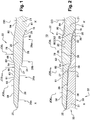
- cross sectional view are partial in the sense that they are sectional view along a plane transverse to a longitudinal axis of the tubular member, and only one of the two cross-section of the tubular member is shown.
- FIG. 2 An embodiment of a threaded tubular connection 10 having a longitudinal axis X-X' is illustrated on Figure 2 ; said threaded tubular connection 10 comprising a first tubular member 22 and a second tubular member 32.
- the first tubular member 22 is provided with a main body 21 referred to as “female main body” and a tubular female end 20 referred to as “box member”.
- the box member 20 extends from the female main body 21.
- the box member 20 defines a terminal end 25 of said first tubular member 22.
- the terminal end 25 is a female free end of the box member 20.
- Female main body 21 presents a nominal outer diameter which is substantially constant over the length of that main body 21 along XX' axis.
- an inner diameter ID of that female main body 21 is substantially constant over the length of that main body 21 along XX' axis.
- the second tubular member 32 is provided with a main body 31 referred to as “male main body” and a tubular male end 30 referred to as "pin member”.
- the pin member 30 extends from the male main body 31.
- the pin member 30 defines a terminal end 35 of said second tubular member 32.
- the terminal end 35 is a male free end of the pin member 30.
- Male main body 31 presents a nominal outer diameter which is substantially constant over the length of that main body 31 along XX' axis.
- an inner diameter of that male main body 31 is substantially constant over the length of that main body 31 along XX' axis.
- Main bodies 21 and 31 have same nominal inner diameter ID and nominal outer diameter OD, and thus same pipe width.
- the threaded tubular connection 10 as illustrated is an integral connection in contrast to assemblies or junctions using a coupling or a sleeve.
- the box member extends from main body 21 at one end along the XX' axis
- a pin member identical to the pin member of the second tubular member 32 extends from the main body 21 at an opposite end along that XX' axis.
- the pin member extends from main body 31 at one end along the XX' axis
- a box member identical to the box member of the first tubular member 22 extends from the main body 31 at an opposite end along that XX' axis.
- An expanded zone of the first tubular member 22 having a greater diameter than nominal outer diameter of main bodies 21 and 31 forms the box member 20.
- a swaged zone of the second tubular member 32 having a reduced inner diameter compared to a nominal inner diameter of the male main body 31 forms pin member 30.
- the first tubular element is first swelled, by using for example cold forming techniques, to expand the outer diameter of the entire box member and to provide a conical tapered outer surface 80 forming an angle ⁇ 1 comprised between 3° and 4°, for example equal to 3°, with the outer cylindrical surface of the female main body 21.
- the second tubular element is first swaged, by using for example cold forming techniques, to reduce the inner diameter of the entire pin member and to provide a conical inner surface 90 forming an angle ⁇ 3 comprised between 3° and 4°, for example equal to 3°, with the inner cylindrical surface of the male main body 31.
- the threaded tubular connection 10 may be a threaded flush or semi-flush integral connection.
- the free end 25 is preferably an annular surface defined perpendicularly to the XX' axis.
- the box member 20 comprises on its inner profile a female external thread 26, a female internal thread 28, and a female intermediate sealing surface 27 such that the female external sealing surface 27 is located between the female external thread 26 and the female internal thread 28.
- the box member 30 may further comprises successively a female shoulder 24 located between the female external thread 26 and the female internal thread 28.
- the female shoulder 24 is said intermediate shoulder.
- the female external and internal threads 26 and 28 are radially offset and axially separated by the female shoulder 24.
- Female shoulder 24 preferably extends as an annular surface perpendicular to the XX' axis.
- Figure 5 is distinguishable from the embodiments of Figures 1 and 2 in that sense that the intermediate metal-to-metal seal is located between the intermediate shoulder 24 and the female internal thread.
- the box member 30 doesn't comprise any intermediate shoulder 24.
- female external and internal threads 26 and 28 are not radially offset, and are aligned along a same tapered profile.
- the box member 30 further comprises a female internal sealing surface 29 and an additional shoulder 18, said internal shoulder 18.
- the female internal sealing surface 29 is located between the female internal thread 28 and the internal shoulder 18.
- the internal shoulder 18 is connected to an inner junction surface 81 defined between the internal shoulder 18 and the female main body 21.
- the inner profile of the box member 20 is machined on the inner surface after having been expanded.
- the female external and internal threads 26 and 28 are provided on tapered surface, for example with a taper value between 1/18 and 1/8. More particularly, a taper angle between a tapering axis of the female threads and the longitudinal axis XX' of the connection is at approximately 10°, such that the inner diameter of the box member 20 decreases towards the female main body 21.
- the female external and internal threads 26 and 28 may have the following features :
- the female external and internal threads 26 and 28 are configured to interlock by thread engagement with respectively the male external and internal threads 36 and 38, such that they are respectively tapered along a same taper angle.
- the male external and internal threads 36 and 38 have the same pitch, same as those of the female external and internal threads 26 and 28 respectively.
- Each tooth of the threads may conventionally include a stabbing flank, a loading flank, a crest surface and a root surface.
- the teeth of both threaded sections may be inclined so that the stabbing flanks have a negative angle and the stabbing flanks have a positive angle, or the stabbing flanks have a positive angle and the stabbing flanks have a negative angle.
- the teeth of both threaded sections may be trapezoidal teeth.
- the threads according to the invention present loading flanks and stabbing flanks with the exact same pitch and lead.
- threads of both threaded sections are wedge.
- Wedge threads are characterized by threads, regardless of a particular thread form, that increase in width as they become farther from the free end.
- the threads according to the invention present a diametrical interference.
- the female external and internal threads 26 and 28 are configured to interlock by thread engagement with corresponding features of the pin member 30.
- interlock by thread engagement it is encompassed that at least 2, and preferably at least 3 turns of a female thread is meshed within a spiralled groove defined between corresponding 2 to 3 turns of the male thread.
- each teeth of a male thread is located in between two adjacent teeth of the female thread, this being observable for at least 3 turns of a thread. At the end of make-up, threads are meshed.
- the pin member 30 comprises successively as from the male free end 35 on its external profile: a male inner sealing surface 39, the male internal thread 38, a male intermediate shoulder 34, a male intermediate sealing surface 37, and a male external thread 36 and a junction surface 91 to the male main body 31.
- the outer profile of the pin member 30 is machined on the outer surface after having been swaged.
- the male external and internal threads 36 and 38 are radially offset and axially separated by the male shoulder 34.
- Male shoulder 34 preferably extends as an annular surface perpendicular to the XX' axis.
- each of the female external and internal threads 26 and 28 comprises a run-in portion 26a and respectively 28a on the side of the female free end 25 and a run-out portion 26b and respectively 28b on the opposite side.
- Run-in thread and run-out thread are imperfect thread in the sense that they do not have the full height that is observed for the thread portion in between respective run-in and run-out portions.
- Each of the male external and internal threads 36 and 38 comprises a run-in portion 36a and respectively 38a on the side of the male free end 35 and a run-out portion 36b and respectively 38b on the opposite side.
- Each run-in portion 26a and respectively 28a on the box member 20 engages a run-out portion 36b and respectively 38b on the pin member 30, and each run-in portion 36a and respectively 38a on the pin member 30 engages a run-out portion 26b and respectively 28b on the box member 20.
- female and male thread comprises those run-in and run-out section.
- the connection may comprise only full height thread.
- a first engaged thread root of the female thread is the first tread root location, when considering successive thread root starting from the run-in portion 26a or 28a of the female external and respectively internal thread, where a corresponding thread of the male thread 36 or 38 is engaged.
- An engaged thread means that at least a portion of the loading flank of the female thread is contacting the corresponding loading flank of the male thread in the made up state.
- a first engaged thread root of the male thread is the first tread root location, when considering successive thread root starting from the run-in portion 36a or 38a of the male external and respectively internal thread, where a corresponding thread of the female thread 26 or 28 is engaged.
- An engaged thread means that at least a portion of the loading flank of the male thread is contacting the corresponding loading flank of the female thread in the made up state.
- the female internal shoulder 18 abuts with a corresponding pin free end 35, and female thread cooperate with corresponding male thread such that at least one of the stabbing flanks and the loading flanks are abutting each other.
- the first engaged thread root of the female external thread is within the run-in portion 26a, and the first engaged thread root of the female internal thread is within the run-in portion 28a.
- the first engaged thread root of the male external thread is within the run-in portion 36a, and the first engaged thread root of the male internal thread is within the run-in portion 38a.
- BCCS2 is a section defined transversely to the XX' axis across the box member at the first engaged thread root of the female internal thread. According to Figures 1 to 5 , BCCS2 falls within the run in portion 28a. BCCS2 is closer from the female internal sealing surface 29 than the female shoulder 24.
- a box critical cross section is a cross-sectional area of the box member 20 which undergoes the maximum tension transferred across all threads and defines efficiency of the connection.
- the female intermediate sealing surface 27 is conical, and the male intermediate sealing surface 37 is also conical.
- the taper of the conical surfaces 27 and 37 may be equal, for example of 1 ⁇ 2.
- Female and male intermediate sealing surface 27 and 37 create a metal-to-metal seal in a made up position of the connection 10.
- the female internal sealing surface 29 is a convexly bulged surface for example a torical surface defined by a torus radius between 10 and 100mm, for example equal to 60mm; and the male internal sealing surface 39 is conical.
- Female and male internal sealing surface 29 and 39 create a metal-to-metal seal in a made up position of the connection 10.
- external and internal metal-to-metal seal can be both of the cone-to-cone type with a substantially same taper.
- female and male intermediate sealing surface 27 and 37 may define a tore-to-cone metal-to-metal seal.
- Diametrical interference value is the maximum difference between an outer diameter of the male sealing surface minus an inner diameter of the female sealing surface, diameters being considered at a same location along the XX' axis when the connection is made up, but diameter are those prior make-up.
- Diametrical interference is defined prior make up, based on FEA analysis and predictable final position of respectively the pin member into the box member at the end of make up.
- diametrical interference of the intermediate metal-to-metal seal is comprised between 0.2 mm and 1.2 mm; preferably between 0.4 mm and 0.8 mm.
- diametrical interference of the internal metal-to-metal seal is comprised between 0.3 mm and 1.7 mm; preferably between 0.7 mm and 1.5 mm.
- diametrical interference of the intermediate metal-to-metal seal is set below the diametrical interference of the internal metal-to-metal seal.
- the box member 20 outer surface is partially machined. Above the female intermediate sealing surface 27, the box member is machined in order to provide locally a cylindrical surface 60 with a minimal outer diameter JOBmin. Cylindrical surface 60 is cylindrical within tolerances of machining of metal parts.
- Machined cylindrical surface 60 extends on both sides of the female intermediate sealing surface 27. According to preferred embodiments of the invention, the machined cylindrical surface 60 is not extending above any of the female external or internal threads 26 and respectively 28. For example, where the run-in portion 26a of the female external threads 26 starts, the machined cylindrical portion 60 ends, and when the run-out portion 28b of the female internal threads 28 starts, the machined cylindrical portion 60 ends.
- the machined cylindrical portion 60 extends on the whole longitudinal length along the X-X' axis between the the female external thread 26 and the internal threads 28.
- the second cylindrical surface 60 has a length along the XX' axis comprised between 10 mm and 100 mm.
- Machined cylindrical surface 60 has adjacent radiused or tronconical portions 61 and respectively 62, on both side, in order to join an external cylindrical portion 58 and an internal cylindrical portion 78.
- External cylindrical portion 58 and internal cylindrical portion 78 each respectively present a constant diameter equal to an external outer diameter JOBe and respectively an internal outer diameter JOBi.
- Tronconical portions 61 and respectively 62 may be tapered with a taper angle comprised between 3° and 45°, preferably between 5° and 15°.
- the external cylindrical portion 58 and the internal cylindrical portion 78 have a length along the XX' axis of at least 25 mm.
- adjacent portions 61 and 62 of the machined cylindrical portion 60 extend respectively above at least the run-in portion 26a of the female external threads 26, and respectively above the run-out portion 28b of the female internal threads 28. Adjacent portions 61 and 62 may also extend above full height thread of the respective female external and internal thread 26 and 28.
- the external outer diameter JOBe and respectively the internal outer diameter JOBi are defined at location above at least one thread root of the female external thread 26 and respectively the female internal thread 28.
- external cylindrical portion 58 and internal cylindrical portion 78 extend respectively above the full height thread of the respective female external and internal thread 26 and 28.
- both external outer diameter JOBe and respectively internal outer diameter JOBi are strictly superior to the minimum outer diameter JOBmin.
- external outer diameter JOBe and internal outer diameter JOBi are equal.
- Adjacent portions 61 and 62 are connecting the machined cylindrical surface 60 having the minimal outer diameter JOBmin by concave toric surfaces respectively 63 and 64. Respectively the adjacent portions 61 and 62 are connecting the external cylindrical portion 58 and the internal cylindrical portion 78 by convex toric surfaces respectively 65 and 66.
- the female member comprises tapered tronconical portions 61 and 62.
- both tapered tronconical portions 61 and 62 are presenting a same taper angle value.
- adjacent portions 61 and 62 may be concave radiused portions curved with a radius of curvature larger than the radius of curvature of the concave toric surfaces respectively 63 and 64.
- concave radiused portions 61 and 62 may present a same radius of curvature equal to 100 mm or above.
- Figures 3 to 5 are representing distinct embodiments according to the invention wherein the adjacent portions 61 and 62 are concave radiused portions curved such that respective adjacent portions 61 and 62 are presenting radius of curvature of distinct value, for example a radius of curvature of adjacent portion 61 which is located between the external cylindrical portion 58 and the machined cylindrical surface 60 is greater than a radius of curvature of adjacent portion 61 which is located between the machined cylindrical surface 60 and the internal cylindrical portion 78.
- the internal cylindrical portion 78 connects the conical tapered outer surface 80 forming the angle ⁇ 1.
- the conical tapered outer surface 80 expands above a groove 50 located between the female internal thread 28 and the female internal sealing surface 29.
- Figures 1 and 2 the conical tapered outer surface 80 further expands over the female internal sealing surface 29, whereas Figures 3 and 4 , the conical tapered outer surface 80 connects with an outer female surface 84 of the main body 21 such that the outer female surface 84 is cylindrical and located above the female internal sealing surface 29.
- delta (JOBe-JOBmin) or (JOBi- JOBmin) between the minimal outer diameter (JOBmin) and respectively the external and the internal outer diameter (JOBe; JOBi) is below a maximum diametrical interference value of the intermediate metal-to-metal seal, for example a ratio between the above delta and the diametrical interference is comprised between 30% and 80%, preferably 40% and 70%.
- outer diameter dimensions are modified all along the box member 20 due to either and/or both thread interference and metal-to-metal seal interference.
- Figures 2 to 5 represent threaded connection at the end of make-up, but in order to allow better description of these embodiments, locations of JOBe, JOBi and JOBmin are identified on those figures, but only point out respective former locations of those specific dimensions, as machined and prior make up.
- the machined cylindrical surface 60 may not be cylindrical anymore, and the same for all outer surfaces. But thanks to the invention, after make up, at all location of the box member 20 the outer diameter of the connection 10 remains below a threshold of 105%, and preferably 103%, and more preferably 101% of the nominal outer diameter of the female main body 21.
- the thickness of the box member 20 at the second critical cross section BCCS2 allows to the box member to have a better casing wear robustness, while allowing the connection to have a good efficiency.
- connection Thanks to the additional thickness at box critical cross sections, the connection have a better casing wear robustness, while having a better efficiency and good performance when the connection is subjected to axial tension.
- the service life of the connection is also improved since the free end of the box member is not in direct radial contact.
Landscapes
- Engineering & Computer Science (AREA)
- Geology (AREA)
- Life Sciences & Earth Sciences (AREA)
- Mining & Mineral Resources (AREA)
- Physics & Mathematics (AREA)
- Environmental & Geological Engineering (AREA)
- Fluid Mechanics (AREA)
- Mechanical Engineering (AREA)
- General Life Sciences & Earth Sciences (AREA)
- Geochemistry & Mineralogy (AREA)
- Non-Disconnectible Joints And Screw-Threaded Joints (AREA)
- Joints With Pressure Members (AREA)
- Earth Drilling (AREA)
Priority Applications (14)
| Application Number | Priority Date | Filing Date | Title |
|---|---|---|---|
| PL18305641T PL3572613T3 (pl) | 2018-05-25 | 2018-05-25 | Rurowe połączenie gwintowane do okładzin |
| EP18305641.5A EP3572613B1 (fr) | 2018-05-25 | 2018-05-25 | Raccord tubulaire fileté pour boîtier |
| JP2020565762A JP7410885B2 (ja) | 2018-05-25 | 2019-05-24 | ケーシングのための管状ねじ接続部 |
| EA202092415A EA039255B1 (ru) | 2018-05-25 | 2019-05-24 | Резьбовое трубное соединение для обсадной колонны |
| PCT/EP2019/063434 WO2019224343A1 (fr) | 2018-05-25 | 2019-05-24 | Raccord tubulaire fileté pour tubage |
| AU2019274791A AU2019274791B2 (en) | 2018-05-25 | 2019-05-24 | Threaded tubular connection for casing |
| BR112020021026-9A BR112020021026B1 (pt) | 2018-05-25 | 2019-05-24 | Conexão tubular rosqueada para envoltório |
| EP19725372.7A EP3803027A1 (fr) | 2018-05-25 | 2019-05-24 | Raccord tubulaire fileté pour tubage |
| ARP190101407A AR115218A1 (es) | 2018-05-25 | 2019-05-24 | Conexión tubular roscada para tuberías de revestimiento |
| CA3096758A CA3096758A1 (fr) | 2018-05-25 | 2019-05-24 | Raccord tubulaire filete pour tubage |
| MX2020012650A MX2020012650A (es) | 2018-05-25 | 2019-05-24 | Conexion tubular roscada para tuberias de revestimiento. |
| UAA202007090A UA126991C2 (uk) | 2018-05-25 | 2019-05-24 | Нарізне трубне з'єднання для обсадної колони |
| US17/054,705 US11905766B2 (en) | 2018-05-25 | 2019-05-24 | Threaded tubular connection for casing |
| CN201980033596.6A CN112469881B (zh) | 2018-05-25 | 2019-05-24 | 用于套管的螺纹管形连接器 |
Applications Claiming Priority (1)
| Application Number | Priority Date | Filing Date | Title |
|---|---|---|---|
| EP18305641.5A EP3572613B1 (fr) | 2018-05-25 | 2018-05-25 | Raccord tubulaire fileté pour boîtier |
Publications (2)
| Publication Number | Publication Date |
|---|---|
| EP3572613A1 true EP3572613A1 (fr) | 2019-11-27 |
| EP3572613B1 EP3572613B1 (fr) | 2020-10-21 |
Family
ID=62528376
Family Applications (2)
| Application Number | Title | Priority Date | Filing Date |
|---|---|---|---|
| EP18305641.5A Active EP3572613B1 (fr) | 2018-05-25 | 2018-05-25 | Raccord tubulaire fileté pour boîtier |
| EP19725372.7A Withdrawn EP3803027A1 (fr) | 2018-05-25 | 2019-05-24 | Raccord tubulaire fileté pour tubage |
Family Applications After (1)
| Application Number | Title | Priority Date | Filing Date |
|---|---|---|---|
| EP19725372.7A Withdrawn EP3803027A1 (fr) | 2018-05-25 | 2019-05-24 | Raccord tubulaire fileté pour tubage |
Country Status (13)
| Country | Link |
|---|---|
| US (1) | US11905766B2 (fr) |
| EP (2) | EP3572613B1 (fr) |
| JP (1) | JP7410885B2 (fr) |
| CN (1) | CN112469881B (fr) |
| AR (1) | AR115218A1 (fr) |
| AU (1) | AU2019274791B2 (fr) |
| BR (1) | BR112020021026B1 (fr) |
| CA (1) | CA3096758A1 (fr) |
| EA (1) | EA039255B1 (fr) |
| MX (1) | MX2020012650A (fr) |
| PL (1) | PL3572613T3 (fr) |
| UA (1) | UA126991C2 (fr) |
| WO (1) | WO2019224343A1 (fr) |
Cited By (2)
| Publication number | Priority date | Publication date | Assignee | Title |
|---|---|---|---|---|
| FR3098878A1 (fr) * | 2019-07-19 | 2021-01-22 | Vallourec Oil And Gas France | Joint fileté pour colonne de cuvelage de puits de pétrole |
| EP4092303A4 (fr) * | 2020-01-17 | 2023-01-25 | Nippon Steel Corporation | Raccord fileté pour tuyau |
Citations (4)
| Publication number | Priority date | Publication date | Assignee | Title |
|---|---|---|---|---|
| US6347814B1 (en) * | 1999-02-19 | 2002-02-19 | Eni S.P.A. | Integral joint for the connection of two pipes |
| US20120325361A1 (en) * | 2010-02-17 | 2012-12-27 | Vallourec Mannesmann Oil & Gas France | Expansible threaded joint and method for making same |
| US20140084582A1 (en) * | 2012-09-21 | 2014-03-27 | Russell ELDER | Tubular threaded connection |
| US20170101830A1 (en) * | 2014-06-20 | 2017-04-13 | Nippon Steel & Sumitomo Metal Corporation | Threaded joint for steel pipes |
Family Cites Families (10)
| Publication number | Priority date | Publication date | Assignee | Title |
|---|---|---|---|---|
| US5154452A (en) * | 1991-09-18 | 1992-10-13 | Frederick William Johnson | Tubular connection with S-thread form for clamping center seal |
| FR2852076B1 (fr) | 2003-03-07 | 2005-06-10 | Vallourec Mannesmann Oil & Gas | Procede de realisation d'un joint filete tubulaire etanche par expansion radiale |
| FR2863031B1 (fr) * | 2003-11-28 | 2006-10-06 | Vallourec Mannesmann Oil & Gas | Realisation, par expansion plastique, d'un assemblage de deux joints tubulaires filetes etanches avec une sous-epaisseur de matiere locale et initiale |
| JP2007205361A (ja) * | 2004-08-27 | 2007-08-16 | Sumitomo Metal Ind Ltd | 鋼管用ねじ継手 |
| US8177262B2 (en) * | 2005-07-28 | 2012-05-15 | Hydril Company Lp | Mid-seal for expandable connections |
| JP5660308B2 (ja) * | 2010-06-30 | 2015-01-28 | Jfeスチール株式会社 | 鋼管用ねじ継手 |
| CN203527851U (zh) * | 2013-08-07 | 2014-04-09 | 安徽省新方尊铸造科技有限公司 | 一种新型螺杆套筒 |
| CN204329797U (zh) * | 2014-12-03 | 2015-05-13 | 西安三环科技开发总公司 | 气密封螺纹接头内螺纹参数测量校准工具 |
| RU161428U1 (ru) * | 2015-08-21 | 2016-04-20 | Открытое акционерное общество "Первоуральский новотрубный завод" | Труба для скважин |
| CN204986094U (zh) * | 2015-09-19 | 2016-01-20 | 华南理工大学 | 一种长寿命的高压油管密封接头 |
-
2018
- 2018-05-25 PL PL18305641T patent/PL3572613T3/pl unknown
- 2018-05-25 EP EP18305641.5A patent/EP3572613B1/fr active Active
-
2019
- 2019-05-24 JP JP2020565762A patent/JP7410885B2/ja active Active
- 2019-05-24 EP EP19725372.7A patent/EP3803027A1/fr not_active Withdrawn
- 2019-05-24 WO PCT/EP2019/063434 patent/WO2019224343A1/fr active Application Filing
- 2019-05-24 EA EA202092415A patent/EA039255B1/ru unknown
- 2019-05-24 UA UAA202007090A patent/UA126991C2/uk unknown
- 2019-05-24 AR ARP190101407A patent/AR115218A1/es active IP Right Grant
- 2019-05-24 AU AU2019274791A patent/AU2019274791B2/en active Active
- 2019-05-24 MX MX2020012650A patent/MX2020012650A/es unknown
- 2019-05-24 CA CA3096758A patent/CA3096758A1/fr active Pending
- 2019-05-24 BR BR112020021026-9A patent/BR112020021026B1/pt active IP Right Grant
- 2019-05-24 CN CN201980033596.6A patent/CN112469881B/zh active Active
- 2019-05-24 US US17/054,705 patent/US11905766B2/en active Active
Patent Citations (5)
| Publication number | Priority date | Publication date | Assignee | Title |
|---|---|---|---|---|
| US6347814B1 (en) * | 1999-02-19 | 2002-02-19 | Eni S.P.A. | Integral joint for the connection of two pipes |
| US20120325361A1 (en) * | 2010-02-17 | 2012-12-27 | Vallourec Mannesmann Oil & Gas France | Expansible threaded joint and method for making same |
| US20140084582A1 (en) * | 2012-09-21 | 2014-03-27 | Russell ELDER | Tubular threaded connection |
| WO2014044773A2 (fr) | 2012-09-21 | 2014-03-27 | Vallourec Oil And Gas France | Raccord vissé tubulaire |
| US20170101830A1 (en) * | 2014-06-20 | 2017-04-13 | Nippon Steel & Sumitomo Metal Corporation | Threaded joint for steel pipes |
Cited By (6)
| Publication number | Priority date | Publication date | Assignee | Title |
|---|---|---|---|---|
| FR3098878A1 (fr) * | 2019-07-19 | 2021-01-22 | Vallourec Oil And Gas France | Joint fileté pour colonne de cuvelage de puits de pétrole |
| WO2021013646A1 (fr) * | 2019-07-19 | 2021-01-28 | Vallourec Oil And Gas France | Raccord fileté pour colonne de tubage d'un puits de pétrole |
| US12054994B2 (en) | 2019-07-19 | 2024-08-06 | Vallourec Oil And Gas France | Threaded connection for casing string of an oil well |
| EP4092303A4 (fr) * | 2020-01-17 | 2023-01-25 | Nippon Steel Corporation | Raccord fileté pour tuyau |
| AU2020423748B2 (en) * | 2020-01-17 | 2023-09-07 | Nippon Steel Corporation | Threaded connection for pipe |
| US12007045B2 (en) | 2020-01-17 | 2024-06-11 | Nippon Steel Corporation | Threaded connection for pipe |
Also Published As
| Publication number | Publication date |
|---|---|
| CN112469881A (zh) | 2021-03-09 |
| EP3803027A1 (fr) | 2021-04-14 |
| BR112020021026B1 (pt) | 2023-01-31 |
| AU2019274791B2 (en) | 2023-12-21 |
| JP2021525342A (ja) | 2021-09-24 |
| JP7410885B2 (ja) | 2024-01-10 |
| EA039255B1 (ru) | 2021-12-23 |
| WO2019224343A1 (fr) | 2019-11-28 |
| UA126991C2 (uk) | 2023-03-01 |
| CA3096758A1 (fr) | 2019-11-28 |
| EA202092415A1 (ru) | 2021-01-27 |
| EP3572613B1 (fr) | 2020-10-21 |
| US20210071483A1 (en) | 2021-03-11 |
| PL3572613T3 (pl) | 2021-05-04 |
| AR115218A1 (es) | 2020-12-09 |
| AU2019274791A1 (en) | 2020-11-26 |
| US11905766B2 (en) | 2024-02-20 |
| BR112020021026A2 (pt) | 2021-01-19 |
| MX2020012650A (es) | 2021-02-02 |
| CN112469881B (zh) | 2023-11-03 |
Similar Documents
| Publication | Publication Date | Title |
|---|---|---|
| US11753877B2 (en) | Tubular threaded connection | |
| EP3803028B1 (fr) | Connexion filetée tubulaire | |
| US11905766B2 (en) | Threaded tubular connection for casing | |
| OA19855A (en) | Threaded tubular connection for casing. | |
| OA19854A (en) | Tubular threaded connection. | |
| OA19882A (en) | Tubular threaded connection. | |
| EA040390B1 (ru) | Трубное резьбовое соединение | |
| BR112020021020B1 (pt) | Conexão tubular rosqueada | |
| BR112020021137B1 (pt) | Conexão tubular roscada |
Legal Events
| Date | Code | Title | Description |
|---|---|---|---|
| PUAI | Public reference made under article 153(3) epc to a published international application that has entered the european phase |
Free format text: ORIGINAL CODE: 0009012 |
|
| STAA | Information on the status of an ep patent application or granted ep patent |
Free format text: STATUS: THE APPLICATION HAS BEEN PUBLISHED |
|
| AK | Designated contracting states |
Kind code of ref document: A1 Designated state(s): AL AT BE BG CH CY CZ DE DK EE ES FI FR GB GR HR HU IE IS IT LI LT LU LV MC MK MT NL NO PL PT RO RS SE SI SK SM TR |
|
| AX | Request for extension of the european patent |
Extension state: BA ME |
|
| STAA | Information on the status of an ep patent application or granted ep patent |
Free format text: STATUS: REQUEST FOR EXAMINATION WAS MADE |
|
| GRAP | Despatch of communication of intention to grant a patent |
Free format text: ORIGINAL CODE: EPIDOSNIGR1 |
|
| STAA | Information on the status of an ep patent application or granted ep patent |
Free format text: STATUS: GRANT OF PATENT IS INTENDED |
|
| 17P | Request for examination filed |
Effective date: 20200428 |
|
| RBV | Designated contracting states (corrected) |
Designated state(s): AL AT BE BG CH CY CZ DE DK EE ES FI FR GB GR HR HU IE IS IT LI LT LU LV MC MK MT NL NO PL PT RO RS SE SI SK SM TR |
|
| INTG | Intention to grant announced |
Effective date: 20200525 |
|
| GRAS | Grant fee paid |
Free format text: ORIGINAL CODE: EPIDOSNIGR3 |
|
| GRAA | (expected) grant |
Free format text: ORIGINAL CODE: 0009210 |
|
| STAA | Information on the status of an ep patent application or granted ep patent |
Free format text: STATUS: THE PATENT HAS BEEN GRANTED |
|
| AK | Designated contracting states |
Kind code of ref document: B1 Designated state(s): AL AT BE BG CH CY CZ DE DK EE ES FI FR GB GR HR HU IE IS IT LI LT LU LV MC MK MT NL NO PL PT RO RS SE SI SK SM TR |
|
| REG | Reference to a national code |
Ref country code: GB Ref legal event code: FG4D |
|
| REG | Reference to a national code |
Ref country code: CH Ref legal event code: EP |
|
| REG | Reference to a national code |
Ref country code: IE Ref legal event code: FG4D |
|
| REG | Reference to a national code |
Ref country code: DE Ref legal event code: R096 Ref document number: 602018008944 Country of ref document: DE |
|
| REG | Reference to a national code |
Ref country code: AT Ref legal event code: REF Ref document number: 1326025 Country of ref document: AT Kind code of ref document: T Effective date: 20201115 |
|
| REG | Reference to a national code |
Ref country code: NL Ref legal event code: FP |
|
| REG | Reference to a national code |
Ref country code: NO Ref legal event code: T2 Effective date: 20201021 |
|
| REG | Reference to a national code |
Ref country code: RO Ref legal event code: EPE |
|
| PG25 | Lapsed in a contracting state [announced via postgrant information from national office to epo] |
Ref country code: GR Free format text: LAPSE BECAUSE OF FAILURE TO SUBMIT A TRANSLATION OF THE DESCRIPTION OR TO PAY THE FEE WITHIN THE PRESCRIBED TIME-LIMIT Effective date: 20210122 Ref country code: FI Free format text: LAPSE BECAUSE OF FAILURE TO SUBMIT A TRANSLATION OF THE DESCRIPTION OR TO PAY THE FEE WITHIN THE PRESCRIBED TIME-LIMIT Effective date: 20201021 Ref country code: RS Free format text: LAPSE BECAUSE OF FAILURE TO SUBMIT A TRANSLATION OF THE DESCRIPTION OR TO PAY THE FEE WITHIN THE PRESCRIBED TIME-LIMIT Effective date: 20201021 Ref country code: PT Free format text: LAPSE BECAUSE OF FAILURE TO SUBMIT A TRANSLATION OF THE DESCRIPTION OR TO PAY THE FEE WITHIN THE PRESCRIBED TIME-LIMIT Effective date: 20210222 |
|
| REG | Reference to a national code |
Ref country code: LT Ref legal event code: MG4D |
|
| PG25 | Lapsed in a contracting state [announced via postgrant information from national office to epo] |
Ref country code: BG Free format text: LAPSE BECAUSE OF FAILURE TO SUBMIT A TRANSLATION OF THE DESCRIPTION OR TO PAY THE FEE WITHIN THE PRESCRIBED TIME-LIMIT Effective date: 20210121 Ref country code: SE Free format text: LAPSE BECAUSE OF FAILURE TO SUBMIT A TRANSLATION OF THE DESCRIPTION OR TO PAY THE FEE WITHIN THE PRESCRIBED TIME-LIMIT Effective date: 20201021 Ref country code: IS Free format text: LAPSE BECAUSE OF FAILURE TO SUBMIT A TRANSLATION OF THE DESCRIPTION OR TO PAY THE FEE WITHIN THE PRESCRIBED TIME-LIMIT Effective date: 20210221 Ref country code: LV Free format text: LAPSE BECAUSE OF FAILURE TO SUBMIT A TRANSLATION OF THE DESCRIPTION OR TO PAY THE FEE WITHIN THE PRESCRIBED TIME-LIMIT Effective date: 20201021 Ref country code: ES Free format text: LAPSE BECAUSE OF FAILURE TO SUBMIT A TRANSLATION OF THE DESCRIPTION OR TO PAY THE FEE WITHIN THE PRESCRIBED TIME-LIMIT Effective date: 20201021 |
|
| PG25 | Lapsed in a contracting state [announced via postgrant information from national office to epo] |
Ref country code: HR Free format text: LAPSE BECAUSE OF FAILURE TO SUBMIT A TRANSLATION OF THE DESCRIPTION OR TO PAY THE FEE WITHIN THE PRESCRIBED TIME-LIMIT Effective date: 20201021 |
|
| REG | Reference to a national code |
Ref country code: DE Ref legal event code: R097 Ref document number: 602018008944 Country of ref document: DE |
|
| PG25 | Lapsed in a contracting state [announced via postgrant information from national office to epo] |
Ref country code: SK Free format text: LAPSE BECAUSE OF FAILURE TO SUBMIT A TRANSLATION OF THE DESCRIPTION OR TO PAY THE FEE WITHIN THE PRESCRIBED TIME-LIMIT Effective date: 20201021 Ref country code: SM Free format text: LAPSE BECAUSE OF FAILURE TO SUBMIT A TRANSLATION OF THE DESCRIPTION OR TO PAY THE FEE WITHIN THE PRESCRIBED TIME-LIMIT Effective date: 20201021 Ref country code: EE Free format text: LAPSE BECAUSE OF FAILURE TO SUBMIT A TRANSLATION OF THE DESCRIPTION OR TO PAY THE FEE WITHIN THE PRESCRIBED TIME-LIMIT Effective date: 20201021 Ref country code: LT Free format text: LAPSE BECAUSE OF FAILURE TO SUBMIT A TRANSLATION OF THE DESCRIPTION OR TO PAY THE FEE WITHIN THE PRESCRIBED TIME-LIMIT Effective date: 20201021 |
|
| PLBE | No opposition filed within time limit |
Free format text: ORIGINAL CODE: 0009261 |
|
| STAA | Information on the status of an ep patent application or granted ep patent |
Free format text: STATUS: NO OPPOSITION FILED WITHIN TIME LIMIT |
|
| PG25 | Lapsed in a contracting state [announced via postgrant information from national office to epo] |
Ref country code: DK Free format text: LAPSE BECAUSE OF FAILURE TO SUBMIT A TRANSLATION OF THE DESCRIPTION OR TO PAY THE FEE WITHIN THE PRESCRIBED TIME-LIMIT Effective date: 20201021 |
|
| 26N | No opposition filed |
Effective date: 20210722 |
|
| PG25 | Lapsed in a contracting state [announced via postgrant information from national office to epo] |
Ref country code: AL Free format text: LAPSE BECAUSE OF FAILURE TO SUBMIT A TRANSLATION OF THE DESCRIPTION OR TO PAY THE FEE WITHIN THE PRESCRIBED TIME-LIMIT Effective date: 20201021 |
|
| PG25 | Lapsed in a contracting state [announced via postgrant information from national office to epo] |
Ref country code: SI Free format text: LAPSE BECAUSE OF FAILURE TO SUBMIT A TRANSLATION OF THE DESCRIPTION OR TO PAY THE FEE WITHIN THE PRESCRIBED TIME-LIMIT Effective date: 20201021 |
|
| REG | Reference to a national code |
Ref country code: CH Ref legal event code: PL |
|
| PG25 | Lapsed in a contracting state [announced via postgrant information from national office to epo] |
Ref country code: LU Free format text: LAPSE BECAUSE OF NON-PAYMENT OF DUE FEES Effective date: 20210525 Ref country code: MC Free format text: LAPSE BECAUSE OF FAILURE TO SUBMIT A TRANSLATION OF THE DESCRIPTION OR TO PAY THE FEE WITHIN THE PRESCRIBED TIME-LIMIT Effective date: 20201021 Ref country code: LI Free format text: LAPSE BECAUSE OF NON-PAYMENT OF DUE FEES Effective date: 20210531 Ref country code: CH Free format text: LAPSE BECAUSE OF NON-PAYMENT OF DUE FEES Effective date: 20210531 |
|
| REG | Reference to a national code |
Ref country code: BE Ref legal event code: MM Effective date: 20210531 |
|
| PG25 | Lapsed in a contracting state [announced via postgrant information from national office to epo] |
Ref country code: IE Free format text: LAPSE BECAUSE OF NON-PAYMENT OF DUE FEES Effective date: 20210525 |
|
| PG25 | Lapsed in a contracting state [announced via postgrant information from national office to epo] |
Ref country code: IS Free format text: LAPSE BECAUSE OF FAILURE TO SUBMIT A TRANSLATION OF THE DESCRIPTION OR TO PAY THE FEE WITHIN THE PRESCRIBED TIME-LIMIT Effective date: 20210221 |
|
| PG25 | Lapsed in a contracting state [announced via postgrant information from national office to epo] |
Ref country code: BE Free format text: LAPSE BECAUSE OF NON-PAYMENT OF DUE FEES Effective date: 20210531 |
|
| REG | Reference to a national code |
Ref country code: AT Ref legal event code: UEP Ref document number: 1326025 Country of ref document: AT Kind code of ref document: T Effective date: 20201021 |
|
| PG25 | Lapsed in a contracting state [announced via postgrant information from national office to epo] |
Ref country code: CY Free format text: LAPSE BECAUSE OF FAILURE TO SUBMIT A TRANSLATION OF THE DESCRIPTION OR TO PAY THE FEE WITHIN THE PRESCRIBED TIME-LIMIT Effective date: 20201021 |
|
| PG25 | Lapsed in a contracting state [announced via postgrant information from national office to epo] |
Ref country code: HU Free format text: LAPSE BECAUSE OF FAILURE TO SUBMIT A TRANSLATION OF THE DESCRIPTION OR TO PAY THE FEE WITHIN THE PRESCRIBED TIME-LIMIT; INVALID AB INITIO Effective date: 20180525 |
|
| PG25 | Lapsed in a contracting state [announced via postgrant information from national office to epo] |
Ref country code: MK Free format text: LAPSE BECAUSE OF FAILURE TO SUBMIT A TRANSLATION OF THE DESCRIPTION OR TO PAY THE FEE WITHIN THE PRESCRIBED TIME-LIMIT Effective date: 20201021 |
|
| PGFP | Annual fee paid to national office [announced via postgrant information from national office to epo] |
Ref country code: NL Payment date: 20240418 Year of fee payment: 7 |
|
| PG25 | Lapsed in a contracting state [announced via postgrant information from national office to epo] |
Ref country code: TR Free format text: LAPSE BECAUSE OF FAILURE TO SUBMIT A TRANSLATION OF THE DESCRIPTION OR TO PAY THE FEE WITHIN THE PRESCRIBED TIME-LIMIT Effective date: 20201021 |
|
| PGFP | Annual fee paid to national office [announced via postgrant information from national office to epo] |
Ref country code: GB Payment date: 20240419 Year of fee payment: 7 |
|
| PGFP | Annual fee paid to national office [announced via postgrant information from national office to epo] |
Ref country code: DE Payment date: 20240418 Year of fee payment: 7 |
|
| PGFP | Annual fee paid to national office [announced via postgrant information from national office to epo] |
Ref country code: CZ Payment date: 20240423 Year of fee payment: 7 Ref country code: AT Payment date: 20240419 Year of fee payment: 7 |
|
| PGFP | Annual fee paid to national office [announced via postgrant information from national office to epo] |
Ref country code: RO Payment date: 20240507 Year of fee payment: 7 Ref country code: NO Payment date: 20240419 Year of fee payment: 7 Ref country code: IT Payment date: 20240418 Year of fee payment: 7 Ref country code: FR Payment date: 20240418 Year of fee payment: 7 |
|
| PGFP | Annual fee paid to national office [announced via postgrant information from national office to epo] |
Ref country code: PL Payment date: 20240418 Year of fee payment: 7 |