EP3572277A1 - Vehicular lamp - Google Patents
Vehicular lamp Download PDFInfo
- Publication number
- EP3572277A1 EP3572277A1 EP19175811.9A EP19175811A EP3572277A1 EP 3572277 A1 EP3572277 A1 EP 3572277A1 EP 19175811 A EP19175811 A EP 19175811A EP 3572277 A1 EP3572277 A1 EP 3572277A1
- Authority
- EP
- European Patent Office
- Prior art keywords
- main body
- cover main
- cover member
- vehicular lamp
- work hole
- Prior art date
- Legal status (The legal status is an assumption and is not a legal conclusion. Google has not performed a legal analysis and makes no representation as to the accuracy of the status listed.)
- Granted
Links
Images
Classifications
-
- B—PERFORMING OPERATIONS; TRANSPORTING
- B60—VEHICLES IN GENERAL
- B60Q—ARRANGEMENT OF SIGNALLING OR LIGHTING DEVICES, THE MOUNTING OR SUPPORTING THEREOF OR CIRCUITS THEREFOR, FOR VEHICLES IN GENERAL
- B60Q1/00—Arrangement of optical signalling or lighting devices, the mounting or supporting thereof or circuits therefor
- B60Q1/0064—Arrangement of optical signalling or lighting devices, the mounting or supporting thereof or circuits therefor with provision for maintenance, e.g. changing the light bulb
- B60Q1/007—Arrangement of optical signalling or lighting devices, the mounting or supporting thereof or circuits therefor with provision for maintenance, e.g. changing the light bulb via a removable cap
-
- F—MECHANICAL ENGINEERING; LIGHTING; HEATING; WEAPONS; BLASTING
- F21—LIGHTING
- F21S—NON-PORTABLE LIGHTING DEVICES; SYSTEMS THEREOF; VEHICLE LIGHTING DEVICES SPECIALLY ADAPTED FOR VEHICLE EXTERIORS
- F21S41/00—Illuminating devices specially adapted for vehicle exteriors, e.g. headlamps
- F21S41/10—Illuminating devices specially adapted for vehicle exteriors, e.g. headlamps characterised by the light source
- F21S41/14—Illuminating devices specially adapted for vehicle exteriors, e.g. headlamps characterised by the light source characterised by the type of light source
- F21S41/141—Light emitting diodes [LED]
-
- F—MECHANICAL ENGINEERING; LIGHTING; HEATING; WEAPONS; BLASTING
- F21—LIGHTING
- F21S—NON-PORTABLE LIGHTING DEVICES; SYSTEMS THEREOF; VEHICLE LIGHTING DEVICES SPECIALLY ADAPTED FOR VEHICLE EXTERIORS
- F21S45/00—Arrangements within vehicle lighting devices specially adapted for vehicle exteriors, for purposes other than emission or distribution of light
- F21S45/10—Protection of lighting devices
-
- F—MECHANICAL ENGINEERING; LIGHTING; HEATING; WEAPONS; BLASTING
- F21—LIGHTING
- F21V—FUNCTIONAL FEATURES OR DETAILS OF LIGHTING DEVICES OR SYSTEMS THEREOF; STRUCTURAL COMBINATIONS OF LIGHTING DEVICES WITH OTHER ARTICLES, NOT OTHERWISE PROVIDED FOR
- F21V23/00—Arrangement of electric circuit elements in or on lighting devices
- F21V23/003—Arrangement of electric circuit elements in or on lighting devices the elements being electronics drivers or controllers for operating the light source, e.g. for a LED array
-
- F—MECHANICAL ENGINEERING; LIGHTING; HEATING; WEAPONS; BLASTING
- F21—LIGHTING
- F21V—FUNCTIONAL FEATURES OR DETAILS OF LIGHTING DEVICES OR SYSTEMS THEREOF; STRUCTURAL COMBINATIONS OF LIGHTING DEVICES WITH OTHER ARTICLES, NOT OTHERWISE PROVIDED FOR
- F21V23/00—Arrangement of electric circuit elements in or on lighting devices
- F21V23/06—Arrangement of electric circuit elements in or on lighting devices the elements being coupling devices, e.g. connectors
-
- F—MECHANICAL ENGINEERING; LIGHTING; HEATING; WEAPONS; BLASTING
- F21—LIGHTING
- F21V—FUNCTIONAL FEATURES OR DETAILS OF LIGHTING DEVICES OR SYSTEMS THEREOF; STRUCTURAL COMBINATIONS OF LIGHTING DEVICES WITH OTHER ARTICLES, NOT OTHERWISE PROVIDED FOR
- F21V3/00—Globes; Bowls; Cover glasses
- F21V3/02—Globes; Bowls; Cover glasses characterised by the shape
-
- F—MECHANICAL ENGINEERING; LIGHTING; HEATING; WEAPONS; BLASTING
- F21—LIGHTING
- F21V—FUNCTIONAL FEATURES OR DETAILS OF LIGHTING DEVICES OR SYSTEMS THEREOF; STRUCTURAL COMBINATIONS OF LIGHTING DEVICES WITH OTHER ARTICLES, NOT OTHERWISE PROVIDED FOR
- F21V29/00—Protecting lighting devices from thermal damage; Cooling or heating arrangements specially adapted for lighting devices or systems
- F21V29/10—Arrangement of heat-generating components to reduce thermal damage, e.g. by distancing heat-generating components from other components to be protected
-
- F—MECHANICAL ENGINEERING; LIGHTING; HEATING; WEAPONS; BLASTING
- F21—LIGHTING
- F21W—INDEXING SCHEME ASSOCIATED WITH SUBCLASSES F21K, F21L, F21S and F21V, RELATING TO USES OR APPLICATIONS OF LIGHTING DEVICES OR SYSTEMS
- F21W2107/00—Use or application of lighting devices on or in particular types of vehicles
- F21W2107/10—Use or application of lighting devices on or in particular types of vehicles for land vehicles
-
- F—MECHANICAL ENGINEERING; LIGHTING; HEATING; WEAPONS; BLASTING
- F21—LIGHTING
- F21Y—INDEXING SCHEME ASSOCIATED WITH SUBCLASSES F21K, F21L, F21S and F21V, RELATING TO THE FORM OR THE KIND OF THE LIGHT SOURCES OR OF THE COLOUR OF THE LIGHT EMITTED
- F21Y2115/00—Light-generating elements of semiconductor light sources
- F21Y2115/10—Light-emitting diodes [LED]
Definitions
- the present invention relates to a vehicular lamp.
- the cover member described in JP2009-539213A has a plurality of claw portions serving as retainers for preventing the cover member from falling off the work hole, and the cover member can be rotated in a peripheral direction while the front face of the cover member is fit to the work hole, so that the cover member can be attached to the work hole.
- the cover member described in JP2014-89877A has a configuration in which a desiccant is disposed inside the cover member.
- the space for routing the wiring cord described above cannot be secured, and the wiring cord may interfere with the inside of the cover member.
- a vehicular lamp which can easily attach and detach a cover member and can prevent interference between an inner portion of the cover member and a wiring cord or the like.
- a vehicular lamp including: a light source unit; a housing inside of which the light source unit is disposed and which has a work hole formed therein on a rear side thereof; and a cover member detachably attached to the work hole of the housing, wherein the cover member includes a cover main body configured to close the work hole, a recess portion formed by concaving an outer surface of the cover main body, and a protrusion portion protruding from an inner surface of the cover main body corresponding to the recess portion, and the protrusion portion forms an inclined surface inclined in a diameter-expanding direction from an inner circumferential side toward an outer circumferential side of the cover main body when the cover main body is viewed in a cross-sectional view in an axial direction.
- the vehicular lamp with the foregoing configuration may be configured such that the protrusion portion forms a convex surface curved from the outer circumferential side toward the inner circumferential side of the cover main body when the inner surface of the cover main body is viewed in plan view.
- the vehicular lamp with the foregoing configuration may be configured such that the cover main body has a top wall portion facing the work hole and a peripheral wall portion surrounding a periphery of the top wall portion, and the recess portion and the protrusion portion are provided on the peripheral wall portion.
- the vehicular lamp with the foregoing configuration may be configured such that a plurality of the recess portions and a plurality of the protrusion portions are arranged side by side in a circumferential direction of the peripheral wall portion.
- the vehicular lamp with the foregoing configuration may be configured such that the recess portion is a gripping portion that allows one to grip the cover member.
- the vehicular lamp with the foregoing configuration may be configured such that the cover main body includes a flange portion protruding from the periphery of the peripheral wall portion in the diameter-expanding direction, and a front cylindrical portion positioned forward of the flange portion of the peripheral wall portion and fitted into the work hole, and a plurality of claw portions serving as retainers for preventing the cover member from falling off the work hole are provided circumferentially side by side on the periphery of the front cylindrical portion.
- a vehicular lamp capable of allowing one to easily perform the attaching/detaching operation of the cover member and of preventing interference between the inside of the cover member and the wiring cord.
- a vehicular lamp 100 having a cover member 1 shown in FIGS. 1 to 3 will be described.
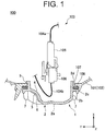
- FIG. 1 is a cross-sectional view showing a configuration example of a vehicular lamp 100 including a cover member 1.
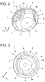
- FIG. 2 is a perspective view of the cover member 1 as viewed from the outer surface side.
- FIG. 3 is a perspective view of the cover member 1 as viewed from the inner surface side.
- the XYZ orthogonal coordinate system is set, and the X-axis direction is indicated as the front-rear direction (length direction) of the vehicular lamp 100, the Y-axis direction is indicated as the left-right direction (width direction) of the vehicular lamp 100, and the Z-axis direction is indicated as the vertical direction (height direction) of the vehicular lamp 100.
- the present invention is applied to a vehicular headlamp to be mounted on both corner portions on the front end side of a vehicle body (not shown).
- the vehicular lamp 100 has a structure in which a light source unit 103 configured to project light toward the front of the vehicle body (+ X-axis direction) is disposed inside a lamp body 102 composed of a housing 101 having a front surface with an opening and a transparent lens cover (not shown) covering the opening of the housing 101.
- the light source unit 103 may adopt a light-emitting diode (LED) that emits white light as a light source (not shown).
- LED light-emitting diode
- a mounting board (not shown) on which LEDs are mounted and a circuit board (not shown) on which a driving circuit for driving LEDs is provided are separately disposed inside the lamp body 102, and these mounting board and circuit board are electrically connected via wiring cords 104a and 104b, thereby protecting the driving circuit from heat generated by the LEDs.
- a plug 105 attached to the wiring cord 104a on the mounting board side is inserted into a socket 106 attached to the wiring cord 104b on the circuit board side, thereby electrically connecting the mounting board and the circuit board.
- the plug 105 is inserted into the socket 106 through a substantially circular work hole 107 provided on the rear surface side of the housing 101.
- the vehicular lamp 100 of the present exemplary embodiment includes a cover member 1 detachably attached to the work hole 107 in order to seal the work hole 107 after the plug 105 has been inserted into the socket 106.
- the cover member 1 has a cover main body 2, a plurality of (three in this embodiment) recess portions 3 in which the outer surface of the cover main body 2 is recessed, and a plurality of (three in this embodiment) protrusion portions 4 projecting from the inner surface of the cover main body 2 corresponding to the respective recess portions 3.
- the cover main body 2 is made of, for example, a molded body of a synthetic resin, and has a cap shape for closing the work hole 107. More specifically, the cover main body 2 includes a top wall portion 2a facing the work hole 107, a peripheral wall portion 2b surrounding the periphery of the top wall portion 2a, a flange portion 2c projected radially from the periphery of the peripheral wall portion 2b, and a front cylindrical portion 2d positioned forward of the flange portion 2c of the peripheral wall portion 2b (on the front surface side) and fitted into the work hole 107.
- a plurality of claw portions 5 are provided around the front cylindrical portion 2d so as to project outward.
- the plurality of claw portions 5 are provided as a fall-off and circumferential retainer for the work hole 107, which will be described later, and are arranged side by side at certain intervals (equally spaced in this embodiment) in the circumferential direction of the front cylindrical portion 2d.
- the positions and the lengths of the claw portions 5 in the circumferential direction are set in accordance with a plurality of notches (not shown) provided around the work hole 107.
- the plurality of recess portions 3 are provided as gripping portions that allow one to grip the cover member 1, and are arranged on the outer surface of the peripheral wall portion 2b side by side in a circumferential direction at certain intervals (equally spaced in this embodiment) on the peripheral wall portion 2b.
- the position of each recess portion 3 coincides with the position of each claw portion 5 in the circumferential direction of the peripheral wall portion 2b.
- Each recess portion 3 forms a concave surface curved from the outer circumferential side of the cover main body to the inner circumferential side when viewing the outer surface of the cover main body 2 in plan view.
- Each recess portion 3 also forms an inclined surface inclined in the diameter-expanding direction from the inner circumferential side to the outer circumferential side of the cover main body when the cover main body 2 is viewed in cross section in the axial direction (X-axis direction).
- Knurled projections 6 that serve as anti-slip projections are provided on the surfaces of the respective recess portions 3 in the circumferential direction of the peripheral wall portion 2b.
- a pair of rib walls 7 are provided so as to protrude from both sides of the circumferential wall portion 2b sandwiching each of the recess portions 3.
- the plurality of protrusion portions 4 are portions projecting toward the inside of the cover main body 2 from positions corresponding to the respective recess portions 3, and have a shape reflecting the respective recess portions 3. That is, the plurality of protrusion portions 4 are provided on the inner surface of the peripheral wall portion 2b so as to be arranged side by side at certain intervals (equally spaced in this embodiment) in the circumferential direction of the peripheral wall portion 2b.
- Each protrusion portion 4 forms a convex surface curved from the outer circumferential side of the cover main body to the inner circumferential side when viewing the inner surface of the cover main body 2 in plan view.
- Each protrusion portion 4 forms an inclined surface inclined in the diameter-expanding direction from the inner circumferential side to the outer circumferential side of the cover main body when the cover main body 2 is viewed in cross section in the axial direction.
- the cover main body 2 When the cover member 1 having the above-described configuration is mounted onto the work hole 107, the cover main body 2 is rotated by a predetermined angle on one side (right turn) in the circumferential direction while the cover member 1 is fit into the work hole 107 in the front cylindrical portion 2d with an O-ring (packing) 108 mounted around the front cylindrical portion 2d, as shown in FIG. 1 .
- the cover main body 2 is rotated to one side in the circumferential direction (clockwise) from the state in which the plurality of claw portions 5 are entering through the plurality of notches formed around the work hole 107, whereby the plurality of claw portions are stopped and retained to the work hole 107.
- the cover member 1 can be attached to the work hole 107.
- the cover main body 2 is operated by a reverse operation relative to the above-described operation of attaching the cover member 1, that is, is rotated by a predetermined angle to the other side in the circumferential direction (counterclockwise) from a state in which the cover member 1 is attached to the work hole 107.
- the cover member 1 can be removed from the work hole 107 by matching the positions of the notches and the claw portions 5.
- the cover member 1 can be easily grasped and rotated by providing a plurality of recess portions 3 (gripping portions) on the outer surface of the cover main body 2. As a result, it is possible to easily perform the attaching and detaching operation of the cover member 1 without securing a sufficient space on the rear surface side of the cover member 1.
- the plurality of protrusion portions 4 projecting from the inner surface of the cover main body 2 form an inclined surface inclined in the diameter-expanding direction from the inner circumferential side toward the outer circumferential side of the cover main body 2.
- variable light distribution headlamp ADB: Adaptive Driving Beam
- ADB Adaptive Driving Beam
- the attachment/detachment operation of the cover member 1 can be easily performed, and it is possible to prevent the wiring cords 104a and 104b from being damaged or the like while preventing the interference or the like between the inside of the cover member 1 and the wiring cords 104a and 104b.
- the present invention is not limited to vehicular lamps to be disposed on the front side described above, but can also be applied to rear side vehicular lamps such as a rear combination lamp.
- the light source unit 103 for example, a halogen lamp, an HID lamp, a laser diode (LD), or the like can be adopted in addition to the LED as the light source.
- the color of the light emitted by the light source is not limited to white light described above, and may be appropriately changed according to the use application of the light source, such as red light or orange light (amber light).
Landscapes
- Engineering & Computer Science (AREA)
- General Engineering & Computer Science (AREA)
- Mechanical Engineering (AREA)
- Microelectronics & Electronic Packaging (AREA)
- Physics & Mathematics (AREA)
- Optics & Photonics (AREA)
- Non-Portable Lighting Devices Or Systems Thereof (AREA)
- Lighting Device Outwards From Vehicle And Optical Signal (AREA)
- Arrangement Of Elements, Cooling, Sealing, Or The Like Of Lighting Devices (AREA)
Abstract
Description
- The present invention relates to a vehicular lamp.
- Conventionally, there has been a known vehicular lamp in which a light source unit is disposed inside a lamp body composed of a housing having a front surface with an opening and a lens cover configured to cover the opening of the housing. In such a vehicular lamp, a work hole is provided on the rear surface of the housing, and a cover member is detachably attached to the work hole to seal the hole. Thus, it is possible to replace the light source unit and route wiring cord, and the like through the work hole (see, for example,
JP2009- 539213A WO2007/141232A1 ) andJP2014-89877A - Incidentally, the cover member described in
JP2009-539213A - However, in the cover member disclosed in
JP2009-539213A - On the other hand, the cover member described in
JP2014-89877A - The present invention was devised in view of these and other problems and features in association with the conventional art. According to an aspect of the present invention, there can be provided a vehicular lamp which can easily attach and detach a cover member and can prevent interference between an inner portion of the cover member and a wiring cord or the like.
- According to another aspect of the present invention, there can be provide a vehicular lamp including: a light source unit; a housing inside of which the light source unit is disposed and which has a work hole formed therein on a rear side thereof; and a cover member detachably attached to the work hole of the housing, wherein the cover member includes a cover main body configured to close the work hole, a recess portion formed by concaving an outer surface of the cover main body, and a protrusion portion protruding from an inner surface of the cover main body corresponding to the recess portion, and the protrusion portion forms an inclined surface inclined in a diameter-expanding direction from an inner circumferential side toward an outer circumferential side of the cover main body when the cover main body is viewed in a cross-sectional view in an axial direction.
- Furthermore, the vehicular lamp with the foregoing configuration may be configured such that the protrusion portion forms a convex surface curved from the outer circumferential side toward the inner circumferential side of the cover main body when the inner surface of the cover main body is viewed in plan view.
- Furthermore, the vehicular lamp with the foregoing configuration may be configured such that the cover main body has a top wall portion facing the work hole and a peripheral wall portion surrounding a periphery of the top wall portion, and the recess portion and the protrusion portion are provided on the peripheral wall portion.
- Furthermore, the vehicular lamp with the foregoing configuration may be configured such that a plurality of the recess portions and a plurality of the protrusion portions are arranged side by side in a circumferential direction of the peripheral wall portion.
- Furthermore, the vehicular lamp with the foregoing configuration may be configured such that the recess portion is a gripping portion that allows one to grip the cover member.
- Furthermore, the vehicular lamp with the foregoing configuration may be configured such that the cover main body includes a flange portion protruding from the periphery of the peripheral wall portion in the diameter-expanding direction, and a front cylindrical portion positioned forward of the flange portion of the peripheral wall portion and fitted into the work hole, and a plurality of claw portions serving as retainers for preventing the cover member from falling off the work hole are provided circumferentially side by side on the periphery of the front cylindrical portion.
- As described above, according to the present invention, it is possible to provide a vehicular lamp capable of allowing one to easily perform the attaching/detaching operation of the cover member and of preventing interference between the inside of the cover member and the wiring cord.
- These and other characteristics, features, and advantages of the present invention will become clear from the following description with reference to the accompanying drawings, wherein:
-
FIG. 1 is a cross-sectional view showing a configuration example of a vehicular lamp provided with a cover member according to an embodiment made in accordance with principles of the present invention; -
FIG. 2 is a perspective view of the cover member shown inFIG. 1 as viewed from the outer surface side; and -
FIG. 3 is a perspective view of the cover member shown inFIG. 1 as viewed from the inner surface side. - A description will now be made below to a vehicular lamp of the present invention with reference to the accompanying drawings in accordance with exemplary embodiments.
- In the drawings used in the following description, in order to make each component easy to see, the scale of the dimension may be shown differently depending on the component, and the dimensional ratio of each component is not necessarily the same as the actual ratio.
- As one exemplary embodiment of the present invention, a
vehicular lamp 100 having acover member 1 shown inFIGS. 1 to 3 , for example, will be described. -
FIG. 1 is a cross-sectional view showing a configuration example of avehicular lamp 100 including acover member 1.FIG. 2 is a perspective view of thecover member 1 as viewed from the outer surface side.FIG. 3 is a perspective view of thecover member 1 as viewed from the inner surface side. - In the drawings shown below, the XYZ orthogonal coordinate system is set, and the X-axis direction is indicated as the front-rear direction (length direction) of the
vehicular lamp 100, the Y-axis direction is indicated as the left-right direction (width direction) of thevehicular lamp 100, and the Z-axis direction is indicated as the vertical direction (height direction) of thevehicular lamp 100. - In the
vehicular lamp 1 of the present exemplary embodiment, for example, the present invention is applied to a vehicular headlamp to be mounted on both corner portions on the front end side of a vehicle body (not shown). - Specifically, as shown in
FIG. 1 , thevehicular lamp 100 has a structure in which alight source unit 103 configured to project light toward the front of the vehicle body (+ X-axis direction) is disposed inside alamp body 102 composed of ahousing 101 having a front surface with an opening and a transparent lens cover (not shown) covering the opening of thehousing 101. - The
light source unit 103 may adopt a light-emitting diode (LED) that emits white light as a light source (not shown). In thelight source unit 103, a mounting board (not shown) on which LEDs are mounted and a circuit board (not shown) on which a driving circuit for driving LEDs is provided are separately disposed inside thelamp body 102, and these mounting board and circuit board are electrically connected viawiring cords - In the
light source unit 103, aplug 105 attached to thewiring cord 104a on the mounting board side is inserted into asocket 106 attached to thewiring cord 104b on the circuit board side, thereby electrically connecting the mounting board and the circuit board. - In the
vehicular lamp 100 of the present exemplary embodiment, theplug 105 is inserted into thesocket 106 through a substantiallycircular work hole 107 provided on the rear surface side of thehousing 101. - The
vehicular lamp 100 of the present exemplary embodiment includes acover member 1 detachably attached to thework hole 107 in order to seal thework hole 107 after theplug 105 has been inserted into thesocket 106. - As shown in
FIGS. 2 and 3 , thecover member 1 has a covermain body 2, a plurality of (three in this embodiment) recessportions 3 in which the outer surface of the covermain body 2 is recessed, and a plurality of (three in this embodiment)protrusion portions 4 projecting from the inner surface of the covermain body 2 corresponding to therespective recess portions 3. - The cover
main body 2 is made of, for example, a molded body of a synthetic resin, and has a cap shape for closing thework hole 107. More specifically, the covermain body 2 includes atop wall portion 2a facing thework hole 107, aperipheral wall portion 2b surrounding the periphery of thetop wall portion 2a, aflange portion 2c projected radially from the periphery of theperipheral wall portion 2b, and a frontcylindrical portion 2d positioned forward of theflange portion 2c of theperipheral wall portion 2b (on the front surface side) and fitted into thework hole 107. - A plurality of claw portions 5 (three in this embodiment) are provided around the front
cylindrical portion 2d so as to project outward. The plurality ofclaw portions 5 are provided as a fall-off and circumferential retainer for thework hole 107, which will be described later, and are arranged side by side at certain intervals (equally spaced in this embodiment) in the circumferential direction of the frontcylindrical portion 2d. The positions and the lengths of theclaw portions 5 in the circumferential direction are set in accordance with a plurality of notches (not shown) provided around thework hole 107. - The plurality of
recess portions 3 are provided as gripping portions that allow one to grip thecover member 1, and are arranged on the outer surface of theperipheral wall portion 2b side by side in a circumferential direction at certain intervals (equally spaced in this embodiment) on theperipheral wall portion 2b. The position of eachrecess portion 3 coincides with the position of eachclaw portion 5 in the circumferential direction of theperipheral wall portion 2b. - Each
recess portion 3 forms a concave surface curved from the outer circumferential side of the cover main body to the inner circumferential side when viewing the outer surface of the covermain body 2 in plan view. Eachrecess portion 3 also forms an inclined surface inclined in the diameter-expanding direction from the inner circumferential side to the outer circumferential side of the cover main body when the covermain body 2 is viewed in cross section in the axial direction (X-axis direction). -
Knurled projections 6 that serve as anti-slip projections are provided on the surfaces of therespective recess portions 3 in the circumferential direction of theperipheral wall portion 2b. In addition, a pair ofrib walls 7 are provided so as to protrude from both sides of thecircumferential wall portion 2b sandwiching each of therecess portions 3. - The plurality of
protrusion portions 4 are portions projecting toward the inside of the covermain body 2 from positions corresponding to therespective recess portions 3, and have a shape reflecting therespective recess portions 3. That is, the plurality ofprotrusion portions 4 are provided on the inner surface of theperipheral wall portion 2b so as to be arranged side by side at certain intervals (equally spaced in this embodiment) in the circumferential direction of theperipheral wall portion 2b. - Each
protrusion portion 4 forms a convex surface curved from the outer circumferential side of the cover main body to the inner circumferential side when viewing the inner surface of the covermain body 2 in plan view. Eachprotrusion portion 4 forms an inclined surface inclined in the diameter-expanding direction from the inner circumferential side to the outer circumferential side of the cover main body when the covermain body 2 is viewed in cross section in the axial direction. - When the
cover member 1 having the above-described configuration is mounted onto thework hole 107, the covermain body 2 is rotated by a predetermined angle on one side (right turn) in the circumferential direction while thecover member 1 is fit into thework hole 107 in the frontcylindrical portion 2d with an O-ring (packing) 108 mounted around the frontcylindrical portion 2d, as shown inFIG. 1 . - At this time, the cover
main body 2 is rotated to one side in the circumferential direction (clockwise) from the state in which the plurality ofclaw portions 5 are entering through the plurality of notches formed around thework hole 107, whereby the plurality of claw portions are stopped and retained to thework hole 107. Thus, thecover member 1 can be attached to thework hole 107. - On the other hand, the cover
main body 2 is operated by a reverse operation relative to the above-described operation of attaching thecover member 1, that is, is rotated by a predetermined angle to the other side in the circumferential direction (counterclockwise) from a state in which thecover member 1 is attached to thework hole 107. Thus, thecover member 1 can be removed from thework hole 107 by matching the positions of the notches and theclaw portions 5. - In the
vehicular lamp 100 of the present exemplary embodiment, thecover member 1 can be easily grasped and rotated by providing a plurality of recess portions 3 (gripping portions) on the outer surface of the covermain body 2. As a result, it is possible to easily perform the attaching and detaching operation of thecover member 1 without securing a sufficient space on the rear surface side of thecover member 1. - In the
vehicular lamp 100 of the present exemplary embodiment, the plurality ofprotrusion portions 4 projecting from the inner surface of the covermain body 2 form an inclined surface inclined in the diameter-expanding direction from the inner circumferential side toward the outer circumferential side of the covermain body 2. As a result, it is possible to prevent thewiring cords wiring cords - In recent years, particularly in a variable light distribution headlamp (ADB: Adaptive Driving Beam) for variably controlling the light distribution of the high beam light distribution pattern by arranging light emitting elements such as LEDs side by side and switching the lighting states of the light emitting elements, the number of wiring codes tends to increase, and therefore, it is particularly useful to adopt the
cover member 1 of the present exemplary embodiment. - As described above, in the
vehicular lamp 100 of the present exemplary embodiment, the attachment/detachment operation of thecover member 1 can be easily performed, and it is possible to prevent thewiring cords cover member 1 and thewiring cords - The present invention is not necessarily limited to the exemplary embodiments described above, and various modifications can be made thereon without departing from the spirit of the present invention.
- For example, in the exemplary embodiment described above, the case where the present invention is applied to a headlamp for a vehicle has been exemplified, but the present invention is not limited to vehicular lamps to be disposed on the front side described above, but can also be applied to rear side vehicular lamps such as a rear combination lamp.
- In the
light source unit 103, for example, a halogen lamp, an HID lamp, a laser diode (LD), or the like can be adopted in addition to the LED as the light source. The color of the light emitted by the light source is not limited to white light described above, and may be appropriately changed according to the use application of the light source, such as red light or orange light (amber light).
Claims (6)
- A vehicular lamp comprising:a light source unit (103);a housing (101) inside of which the light source unit (103) is disposed and which has a work hole (107) formed therein on a rear side thereof; anda cover member (1) detachably attached to the work hole (107) of the housing (101), whereinthe cover member (1) includes a cover main body (2) configured to close the work hole (107), a recess portion (3) formed by concaving an outer surface of the cover main body (2), and a protrusion portion (4) protruding from an inner surface of the cover main body (2) corresponding to the recess portion (3), andthe protrusion portion (4) forms an inclined surface inclined in a diameter-expanding direction from an inner circumferential side toward an outer circumferential side of the cover main body (2) when the cover main body (2) is viewed in a cross-sectional view in an axial direction.
- The vehicular lamp according to claim 1, wherein the protrusion portion (4) forms a convex surface curved from the outer circumferential side toward the inner circumferential side of the cover main body (2) when the inner surface of the cover main body (2) is viewed in plan view.
- The vehicular lamp according to claim 1 or 2, wherein
the cover main body (2) has a top wall portion (2a) facing the work hole (107) and a peripheral wall portion (2b) surrounding a periphery of the top wall portion (2a), and
the recess portion (3) and the protrusion portion (4) are provided on the peripheral wall portion (2b). - The vehicular lamp according to claim 3, wherein a plurality of the recess portions (3) and a plurality of the protrusion portions (4) are arranged side by side in a circumferential direction of the peripheral wall portion (2b).
- The vehicular lamp according to claim 4, wherein the recess portion (3) is a gripping portion that allows one to grip the cover member (1).
- The vehicular lamp according to any one of claims 3 to 5, wherein
the cover main body (2) includes a flange portion (2c) protruding from the periphery of the peripheral wall portion (2b) in the diameter-expanding direction, and a front cylindrical portion (2d) positioned forward of the flange portion (2c) of the peripheral wall portion (2b) and fitted into the work hole (107), and
a plurality of claw portions (5) serving as retainers for preventing the cover member (1) from falling off the work hole (107) are provided circumferentially side by side on the periphery of the front cylindrical portion (2d).
Applications Claiming Priority (1)
| Application Number | Priority Date | Filing Date | Title |
|---|---|---|---|
| JP2018097753A JP7097745B2 (en) | 2018-05-22 | 2018-05-22 | Vehicle lighting |
Publications (2)
| Publication Number | Publication Date |
|---|---|
| EP3572277A1 true EP3572277A1 (en) | 2019-11-27 |
| EP3572277B1 EP3572277B1 (en) | 2025-11-12 |
Family
ID=66630171
Family Applications (1)
| Application Number | Title | Priority Date | Filing Date |
|---|---|---|---|
| EP19175811.9A Active EP3572277B1 (en) | 2018-05-22 | 2019-05-21 | Vehicular lamp |
Country Status (4)
| Country | Link |
|---|---|
| US (1) | US10821876B2 (en) |
| EP (1) | EP3572277B1 (en) |
| JP (1) | JP7097745B2 (en) |
| CN (1) | CN110513650A (en) |
Citations (8)
| Publication number | Priority date | Publication date | Assignee | Title |
|---|---|---|---|---|
| DE3132440A1 (en) * | 1981-08-17 | 1983-02-24 | Robert Bosch Gmbh, 7000 Stuttgart | Headlamp (headlight) for motor vehicles |
| KR19980031091U (en) * | 1996-11-30 | 1998-08-17 | 양재신 | Dustproof stopper handle structure of automobile headlamp |
| DE69422355T2 (en) * | 1993-09-15 | 2000-07-20 | Valeo Vision, Bobigny | Housing and cover cap for motor vehicle headlights or signal lamps |
| DE10010624A1 (en) * | 1999-03-03 | 2000-09-14 | Koito Mfg Co Ltd | Vehicle light |
| WO2007141232A1 (en) | 2006-06-02 | 2007-12-13 | Oxyphen Ag | Air-permeable closure element for closed units |
| KR20130134543A (en) * | 2012-05-31 | 2013-12-10 | 쌍용자동차 주식회사 | Dust cover of headlamp for automobile |
| WO2014009017A1 (en) * | 2012-07-12 | 2014-01-16 | Hella Kgaa Hueck & Co. | Closure system for closing an opening of a vehicle light and vehicle light |
| JP2014089877A (en) | 2012-10-30 | 2014-05-15 | Ichikoh Ind Ltd | Vehicular lighting fixture |
Family Cites Families (13)
| Publication number | Priority date | Publication date | Assignee | Title |
|---|---|---|---|---|
| JP3062912B2 (en) * | 1994-04-26 | 2000-07-12 | 株式会社小糸製作所 | Vehicle lighting |
| JP2000294011A (en) * | 1999-04-07 | 2000-10-20 | Koito Mfg Co Ltd | Automotive lighting |
| JP3898386B2 (en) * | 1999-08-18 | 2007-03-28 | 株式会社小糸製作所 | Vehicle lighting |
| JP3690957B2 (en) * | 2000-03-16 | 2005-08-31 | ダイハツ工業株式会社 | Vehicle lamp structure |
| FR2893701B1 (en) * | 2005-11-24 | 2010-03-26 | Valeo Vision | LIGHTING AND / OR SIGNALING DEVICE FOR A MOTOR VEHICLE |
| JP4775249B2 (en) | 2006-12-22 | 2011-09-21 | トヨタ自動車株式会社 | Vehicle lighting |
| JP5059479B2 (en) * | 2007-04-26 | 2012-10-24 | 株式会社小糸製作所 | Vehicle headlamp |
| KR20080112529A (en) * | 2007-06-21 | 2008-12-26 | 기아자동차주식회사 | Dust cover improvement structure of automotive headlamp |
| JP5545936B2 (en) * | 2009-09-16 | 2014-07-09 | 株式会社小糸製作所 | Vehicle lamp and back cover |
| JP2015079604A (en) * | 2013-10-16 | 2015-04-23 | 株式会社小糸製作所 | Light source device and vehicle lamp |
| JP6191091B2 (en) * | 2013-12-20 | 2017-09-06 | 東芝ライテック株式会社 | Lighting device and lamp |
| JP2016029607A (en) * | 2014-07-25 | 2016-03-03 | スタンレー電気株式会社 | Vehicle lighting |
| CN204268300U (en) * | 2014-11-20 | 2015-04-15 | 敏翔股份有限公司 | car light body structure |
-
2018
- 2018-05-22 JP JP2018097753A patent/JP7097745B2/en active Active
-
2019
- 2019-05-21 US US16/418,656 patent/US10821876B2/en active Active
- 2019-05-21 EP EP19175811.9A patent/EP3572277B1/en active Active
- 2019-05-22 CN CN201910428749.9A patent/CN110513650A/en active Pending
Patent Citations (9)
| Publication number | Priority date | Publication date | Assignee | Title |
|---|---|---|---|---|
| DE3132440A1 (en) * | 1981-08-17 | 1983-02-24 | Robert Bosch Gmbh, 7000 Stuttgart | Headlamp (headlight) for motor vehicles |
| DE69422355T2 (en) * | 1993-09-15 | 2000-07-20 | Valeo Vision, Bobigny | Housing and cover cap for motor vehicle headlights or signal lamps |
| KR19980031091U (en) * | 1996-11-30 | 1998-08-17 | 양재신 | Dustproof stopper handle structure of automobile headlamp |
| DE10010624A1 (en) * | 1999-03-03 | 2000-09-14 | Koito Mfg Co Ltd | Vehicle light |
| WO2007141232A1 (en) | 2006-06-02 | 2007-12-13 | Oxyphen Ag | Air-permeable closure element for closed units |
| JP2009539213A (en) | 2006-06-02 | 2009-11-12 | オクシフェン・アクチエンゲゼルシャフト | Breathable closure element for closure unit |
| KR20130134543A (en) * | 2012-05-31 | 2013-12-10 | 쌍용자동차 주식회사 | Dust cover of headlamp for automobile |
| WO2014009017A1 (en) * | 2012-07-12 | 2014-01-16 | Hella Kgaa Hueck & Co. | Closure system for closing an opening of a vehicle light and vehicle light |
| JP2014089877A (en) | 2012-10-30 | 2014-05-15 | Ichikoh Ind Ltd | Vehicular lighting fixture |
Also Published As
| Publication number | Publication date |
|---|---|
| EP3572277B1 (en) | 2025-11-12 |
| US10821876B2 (en) | 2020-11-03 |
| CN110513650A (en) | 2019-11-29 |
| US20190359115A1 (en) | 2019-11-28 |
| JP2019204628A (en) | 2019-11-28 |
| JP7097745B2 (en) | 2022-07-08 |
Similar Documents
| Publication | Publication Date | Title |
|---|---|---|
| US10836302B2 (en) | Vehicle lamp | |
| US9151481B2 (en) | End piece for a retrofit fluorescent lamp and retrofit fluorescent lamp | |
| KR101853614B1 (en) | Lamp for vehicle | |
| US10190745B2 (en) | Lamp assembly for use in a headlamp | |
| US20130051046A1 (en) | Led aperture of automobile lamp | |
| US20190257489A1 (en) | Light source unit for lighting tool for vehicle and lighting tool for vehicle | |
| WO2017052478A1 (en) | Position light structure for motorcycle | |
| US20140056000A1 (en) | Assembling structure of illumination unit | |
| JP6814069B2 (en) | Vehicle lighting | |
| CN107435882B (en) | lighting device | |
| US10821876B2 (en) | Vehicular lamp | |
| JP2015041454A (en) | LED module and vehicle lamp provided with the same | |
| JP2018120657A (en) | Clamp structure of wiring cord for illumination and luminaire | |
| JP5536348B2 (en) | Vehicle lighting | |
| JP2024534167A (en) | Light-transmitting assembly and vehicle | |
| KR101790044B1 (en) | Lighting apparatus for an automobile | |
| WO2024128289A1 (en) | Light-source unit and vehicle lamp | |
| JP2014170717A (en) | Light source unit and vehicular lighting | |
| WO2012056289A1 (en) | Decoration plate and plate device including same | |
| JP2024118630A (en) | Vehicle lighting fixtures | |
| JP3203318U (en) | LED fog light for convenient repair | |
| JP6592035B2 (en) | Interior lighting | |
| JP4798177B2 (en) | Vehicle lighting | |
| WO2023176582A1 (en) | Light source unit for vehicular lighting fixture, and vehicular lighting fixture | |
| TWM520605U (en) | Easy to repair LED fog light |
Legal Events
| Date | Code | Title | Description |
|---|---|---|---|
| PUAI | Public reference made under article 153(3) epc to a published international application that has entered the european phase |
Free format text: ORIGINAL CODE: 0009012 |
|
| STAA | Information on the status of an ep patent application or granted ep patent |
Free format text: STATUS: THE APPLICATION HAS BEEN PUBLISHED |
|
| AK | Designated contracting states |
Kind code of ref document: A1 Designated state(s): AL AT BE BG CH CY CZ DE DK EE ES FI FR GB GR HR HU IE IS IT LI LT LU LV MC MK MT NL NO PL PT RO RS SE SI SK SM TR |
|
| AX | Request for extension of the european patent |
Extension state: BA ME |
|
| STAA | Information on the status of an ep patent application or granted ep patent |
Free format text: STATUS: REQUEST FOR EXAMINATION WAS MADE |
|
| 17P | Request for examination filed |
Effective date: 20200602 |
|
| RBV | Designated contracting states (corrected) |
Designated state(s): AL AT BE BG CH CY CZ DE DK EE ES FI FR GB GR HR HU IE IS IT LI LT LU LV MC MK MT NL NO PL PT RO RS SE SI SK SM TR |
|
| STAA | Information on the status of an ep patent application or granted ep patent |
Free format text: STATUS: EXAMINATION IS IN PROGRESS |
|
| 17Q | First examination report despatched |
Effective date: 20220324 |
|
| GRAP | Despatch of communication of intention to grant a patent |
Free format text: ORIGINAL CODE: EPIDOSNIGR1 |
|
| STAA | Information on the status of an ep patent application or granted ep patent |
Free format text: STATUS: GRANT OF PATENT IS INTENDED |
|
| INTG | Intention to grant announced |
Effective date: 20250603 |
|
| GRAS | Grant fee paid |
Free format text: ORIGINAL CODE: EPIDOSNIGR3 |
|
| GRAA | (expected) grant |
Free format text: ORIGINAL CODE: 0009210 |
|
| STAA | Information on the status of an ep patent application or granted ep patent |
Free format text: STATUS: THE PATENT HAS BEEN GRANTED |
|
| AK | Designated contracting states |
Kind code of ref document: B1 Designated state(s): AL AT BE BG CH CY CZ DE DK EE ES FI FR GB GR HR HU IE IS IT LI LT LU LV MC MK MT NL NO PL PT RO RS SE SI SK SM TR |
|
| REG | Reference to a national code |
Ref country code: CH Ref legal event code: F10 Free format text: ST27 STATUS EVENT CODE: U-0-0-F10-F00 (AS PROVIDED BY THE NATIONAL OFFICE) Effective date: 20251112 Ref country code: GB Ref legal event code: FG4D |
|
| REG | Reference to a national code |
Ref country code: DE Ref legal event code: R096 Ref document number: 602019077972 Country of ref document: DE |
|
| REG | Reference to a national code |
Ref country code: IE Ref legal event code: FG4D |
|
| REG | Reference to a national code |
Ref country code: NL Ref legal event code: MP Effective date: 20251112 |
|
| PG25 | Lapsed in a contracting state [announced via postgrant information from national office to epo] |
Ref country code: ES Free format text: LAPSE BECAUSE OF FAILURE TO SUBMIT A TRANSLATION OF THE DESCRIPTION OR TO PAY THE FEE WITHIN THE PRESCRIBED TIME-LIMIT Effective date: 20251112 |
|
| REG | Reference to a national code |
Ref country code: LT Ref legal event code: MG9D |
|
| PG25 | Lapsed in a contracting state [announced via postgrant information from national office to epo] |
Ref country code: NO Free format text: LAPSE BECAUSE OF FAILURE TO SUBMIT A TRANSLATION OF THE DESCRIPTION OR TO PAY THE FEE WITHIN THE PRESCRIBED TIME-LIMIT Effective date: 20260212 |
|
| PG25 | Lapsed in a contracting state [announced via postgrant information from national office to epo] |
Ref country code: AT Free format text: LAPSE BECAUSE OF FAILURE TO SUBMIT A TRANSLATION OF THE DESCRIPTION OR TO PAY THE FEE WITHIN THE PRESCRIBED TIME-LIMIT Effective date: 20251112 Ref country code: HR Free format text: LAPSE BECAUSE OF FAILURE TO SUBMIT A TRANSLATION OF THE DESCRIPTION OR TO PAY THE FEE WITHIN THE PRESCRIBED TIME-LIMIT Effective date: 20251112 Ref country code: FI Free format text: LAPSE BECAUSE OF FAILURE TO SUBMIT A TRANSLATION OF THE DESCRIPTION OR TO PAY THE FEE WITHIN THE PRESCRIBED TIME-LIMIT Effective date: 20251112 |
|
| REG | Reference to a national code |
Ref country code: AT Ref legal event code: MK05 Ref document number: 1856491 Country of ref document: AT Kind code of ref document: T Effective date: 20251112 |
|
| PG25 | Lapsed in a contracting state [announced via postgrant information from national office to epo] |
Ref country code: NL Free format text: LAPSE BECAUSE OF FAILURE TO SUBMIT A TRANSLATION OF THE DESCRIPTION OR TO PAY THE FEE WITHIN THE PRESCRIBED TIME-LIMIT Effective date: 20251112 |
|
| PG25 | Lapsed in a contracting state [announced via postgrant information from national office to epo] |
Ref country code: RS Free format text: LAPSE BECAUSE OF FAILURE TO SUBMIT A TRANSLATION OF THE DESCRIPTION OR TO PAY THE FEE WITHIN THE PRESCRIBED TIME-LIMIT Effective date: 20260212 |
|
| PG25 | Lapsed in a contracting state [announced via postgrant information from national office to epo] |
Ref country code: IS Free format text: LAPSE BECAUSE OF FAILURE TO SUBMIT A TRANSLATION OF THE DESCRIPTION OR TO PAY THE FEE WITHIN THE PRESCRIBED TIME-LIMIT Effective date: 20260312 |
|
| PG25 | Lapsed in a contracting state [announced via postgrant information from national office to epo] |
Ref country code: PT Free format text: LAPSE BECAUSE OF FAILURE TO SUBMIT A TRANSLATION OF THE DESCRIPTION OR TO PAY THE FEE WITHIN THE PRESCRIBED TIME-LIMIT Effective date: 20260312 |
|
| PG25 | Lapsed in a contracting state [announced via postgrant information from national office to epo] |
Ref country code: PL Free format text: LAPSE BECAUSE OF FAILURE TO SUBMIT A TRANSLATION OF THE DESCRIPTION OR TO PAY THE FEE WITHIN THE PRESCRIBED TIME-LIMIT Effective date: 20251112 |
|
| PG25 | Lapsed in a contracting state [announced via postgrant information from national office to epo] |
Ref country code: LV Free format text: LAPSE BECAUSE OF FAILURE TO SUBMIT A TRANSLATION OF THE DESCRIPTION OR TO PAY THE FEE WITHIN THE PRESCRIBED TIME-LIMIT Effective date: 20251112 |