EP3572238B1 - Hub for cycle wheel - Google Patents
Hub for cycle wheel Download PDFInfo
- Publication number
- EP3572238B1 EP3572238B1 EP19170683.7A EP19170683A EP3572238B1 EP 3572238 B1 EP3572238 B1 EP 3572238B1 EP 19170683 A EP19170683 A EP 19170683A EP 3572238 B1 EP3572238 B1 EP 3572238B1
- Authority
- EP
- European Patent Office
- Prior art keywords
- hub
- cap
- shaft
- retention element
- pin
- Prior art date
- Legal status (The legal status is an assumption and is not a legal conclusion. Google has not performed a legal analysis and makes no representation as to the accuracy of the status listed.)
- Active
Links
- 230000014759 maintenance of location Effects 0.000 claims description 37
- 239000002184 metal Substances 0.000 claims description 9
- 229910000831 Steel Inorganic materials 0.000 claims description 3
- 239000010959 steel Substances 0.000 claims description 3
- 238000004519 manufacturing process Methods 0.000 description 2
- 238000005452 bending Methods 0.000 description 1
- 230000000295 complement effect Effects 0.000 description 1
- 230000002596 correlated effect Effects 0.000 description 1
- 238000012423 maintenance Methods 0.000 description 1
- 238000000926 separation method Methods 0.000 description 1
Images


Classifications
-
- B—PERFORMING OPERATIONS; TRANSPORTING
- B60—VEHICLES IN GENERAL
- B60B—VEHICLE WHEELS; CASTORS; AXLES FOR WHEELS OR CASTORS; INCREASING WHEEL ADHESION
- B60B27/00—Hubs
- B60B27/02—Hubs adapted to be rotatably arranged on axle
-
- B—PERFORMING OPERATIONS; TRANSPORTING
- B60—VEHICLES IN GENERAL
- B60B—VEHICLE WHEELS; CASTORS; AXLES FOR WHEELS OR CASTORS; INCREASING WHEEL ADHESION
- B60B27/00—Hubs
- B60B27/0015—Hubs for driven wheels
-
- B—PERFORMING OPERATIONS; TRANSPORTING
- B60—VEHICLES IN GENERAL
- B60B—VEHICLE WHEELS; CASTORS; AXLES FOR WHEELS OR CASTORS; INCREASING WHEEL ADHESION
- B60B27/00—Hubs
- B60B27/02—Hubs adapted to be rotatably arranged on axle
- B60B27/023—Hubs adapted to be rotatably arranged on axle specially adapted for bicycles
Description
La présente invention concerne un moyeu pour roue de cycle. Plus particulièrement, la présente invention concerne les bouchons d'axe qui sont placés aux deux extrémités de l'axe central du moyeu et qui viennent en appui contre le cadre ou la fourche du vélo lorsque la roue est fixée au vélo.The present invention relates to a hub for a cycle wheel. More particularly, the present invention relates to the axle caps which are placed at both ends of the central axle of the hub and which bear against the frame or fork of the bicycle when the wheel is fixed to the bicycle.
Il est connu dans l'art antérieur de placer simplement des bouchons d'extrémité en les glissant sur l'axe ou à l'intérieur de celui-ci. Le document
Toutes les solutions de l'art antérieur ne sont pas pleinement satisfaisantes, notamment d'un point de vue industriel. Un des inconvénients majeur de ces solutions réside dans la difficile reproductibilité de la force de rétention du bouchon sur ou dans l'arbre. En effet, comme cette force de rétention est directement corrélée à la relation entre les diamètres respectifs du bouchon et de l'arbre, toute variation de ces diamètres occasionnera des variations de cette force de rétention. En pratique, bien que les tolérances de fabrication soient précises et respectées dans la fabrication de l'arbre et dans celle du bouchon, il n'est pas rare que lors du montage, opérateur se trouve confronté à ne pas pouvoir mettre en place le bouchon sur l'arbre. A l'opposé, un assemblage trop lâche conduira à des risques de voir le bouchon se désolidariser trop facilement de l'arbre.All the solutions of the prior art are not fully satisfactory, particularly from an industrial point of view. One of the major disadvantages of these solutions lies in the difficult reproducibility of the retention force of the plug on or in the tree. Indeed, as this retention force is directly correlated to the relationship between the respective diameters of the plug and the shaft, any variation in these diameters will cause variations in this retention force. In practice, although the manufacturing tolerances are precise and respected in the manufacture of the shaft and in that of the plug, it is not uncommon that during assembly, the operator finds himself unable to put the plug in place. on the tree. On the other hand, an assembly that is too loose will lead to the risk of the plug separating too easily from the shaft.
L'objectif de l'invention est de remédier aux inconvénients de l'art antérieur. En particulier, l'objectif de l'invention est de simplifier le montage des moyeux pour le fabricant, mais également d'en faciliter le démontage et le remontage par les techniciens où les utilisateurs à des fins d'entretien. Enfin, l'objectif de l'invention est d'éviter toute désolidarisation et toute perte de bouchon lorsque la roue n'est pas fixée au cadre du cycle.The objective of the invention is to remedy the disadvantages of the prior art. In particular, the objective of the invention is to simplify the assembly of the hubs for the manufacturer, but also to facilitate their disassembly and reassembly by technicians or users for maintenance purposes. Finally, the objective of the invention is to avoid any separation and any loss of cap when the wheel is not fixed to the cycle frame.
Les objectifs de l'invention sont atteints par la fourniture d'un moyeu pour roue prévu pour être fixé à un élément de cadre d'un cycle comportant un arbre central autour duquel est monté rotatif un corps de moyeu et au moins un capuchon placé à l'extrémité dudit arbre, ledit capuchon comportant une première paroi cylindrique destinée à venir se glisser contre une deuxième paroi cylindrique ménagée sur l'arbre, une surface annulaire intérieure et une surface annulaire extérieure étant définies sur le capuchon et l'arbre, de manière à ménager un espace radial entre elles, ledit moyeu comportant en outre un élément de rétention du capuchon sur l'arbre placé dans ledit espace radial, ledit élément de rétention étant constitué par une épingle métallique dont au moins une portion est en appui simultané et essentiellement ponctuel sur l'arbre central et le capuchon.The objectives of the invention are achieved by providing a hub for a wheel intended to be fixed to a frame element of a cycle comprising a central shaft around which is rotatably mounted a hub body and at least one cap placed at the end of said shaft, said cap comprising a first cylindrical wall intended to slide against a second cylindrical wall provided on the shaft, an interior annular surface and an exterior annular surface being defined on the cap and the shaft, so to provide a radial space between them, said hub further comprising an element for retaining the cap on the shaft placed in said radial space, said retention element being constituted by a metal pin of which at least one portion is in simultaneous support and essentially punctual on the central shaft and the cap.
De préférence, ladite au moins une portion de l'épingle est en appui au niveau de ses deux extrémités sur la surface annulaire extérieure et en contact avec la surface intérieure au niveau d'une zone intermédiaire placée entre lesdites deux extrémités.Preferably, said at least one portion of the pin rests at its two ends on the outer annular surface and in contact with the inner surface at an intermediate zone placed between said two ends.
Dans un mode de réalisation préféré de l'invention, l'épingle a un profil de forme polygonale. Dans un autre mode de réalisation de l'invention, l'épingle a une forme en U.In a preferred embodiment of the invention, the pin has a polygonal shaped profile. In another embodiment of the invention, the pin has a U shape.
Dans un mode de réalisation préféré, l'élément de rétention a un profil comportant au moins six sections droites. Par exemple, dans un mode de réalisation de l'invention, l'élément de rétention a un profil de forme octogonale.In a preferred embodiment, the retention element has a profile comprising at least six straight sections. For example, in one embodiment of the invention, the retention element has an octagonal shaped profile.
Dans un mode de réalisation préféré, la première surface cylindrique est interne, la deuxième surface cylindrique est externe et en ce que le capuchon est glissé à l'extérieur de l'arbre. Dans un autre mode de réalisation, la première surface cylindrique est externe, la deuxième surface cylindrique est interne et en ce que le capuchon est glissé à l'intérieur de l'arbre.In a preferred embodiment, the first cylindrical surface is internal, the second cylindrical surface is external and in that the cap is slid outside the shaft. In another embodiment, the first cylindrical surface is external, the second cylindrical surface is internal and in that the cap is slipped inside the shaft.
De préférence, l'épingle est réalisée dans du fil acier de section inférieure à 1 mm, de préférence inférieur à 0,8 mm.Preferably, the pin is made of steel wire with a section of less than 1 mm, preferably less than 0.8 mm.
Dans un mode de réalisation préféré, la surface annulaire extérieure est réalisée au fond d'une gorge ménagée dans le capuchon. Dans un autre mode de réalisation, la surface annulaire intérieure est réalisée au fond d'une gorge ménagée dans le capuchon.In a preferred embodiment, the outer annular surface is made at the bottom of a groove formed in the cap. In another embodiment, the interior annular surface is made at the bottom of a groove formed in the cap.
La présente invention sera mieux comprise à la lecture de la description auquelle est jointe le dessin comprenant les figures suivantes :
- la
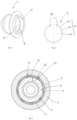
figure 1 est une vue en coupe d'un moyeu selon un premier mode de réalisation de l'invention, - la
figure 2 est une vue en perspective du capuchon selon le premier mode de réalisation de l'invention, - la
figure 3 est une vue de face de l'élément de rétention selon le premier mode de réalisation de l'invention, - la
figure 4 est une section partielle du moyeu au droit de l'élément de rétention, - la
figure 5 est une vue en coupe d'un moyeu selon un deuxième mode de réalisation de l'invention, - la
figure 6 est une vue en coupe partielle d'un moyeu selon un troisième mode de réalisation de l'invention, - la
figure 7 est une vue en perspective éclatée selon un quatrième mode de réalisation de l'invention, - la
figure 8 est une vue en perspective éclatée selon un cinquième mode de réalisation de l'invention.
- there
figure 1 is a sectional view of a hub according to a first embodiment of the invention, - there
figure 2 is a perspective view of the cap according to the first embodiment of the invention, - there
Figure 3 is a front view of the retention element according to the first embodiment of the invention, - there
Figure 4 is a partial section of the hub to the right of the retention element, - there
Figure 5 is a sectional view of a hub according to a second embodiment of the invention, - there
Figure 6 is a partial sectional view of a hub according to a third embodiment of the invention, - there
figure 7 is an exploded perspective view according to a fourth embodiment of the invention, - there
figure 8 is an exploded perspective view according to a fifth embodiment of the invention.
Les
De manière connue, le moyeu comprend un arbre central 3 autour duquel est monté rotatif le corps de moyeu 11 et le corps de roue libre 12. Chacune des extrémités de l'arbre 3 comporte une deuxième paroi cylindrique 32 contre laquelle vient se glisser une première paroi cylindrique 21 ménagée sur le capuchon 2. Le capuchon 2 est une pièce de révolution qui comporte une face frontale 23 et un embout 24 destinés à venir en contact avec des surfaces complémentaires ménagées sur la fourche ou sur le cadre du cycle.In known manner, the hub comprises a
Dans ce premier mode de réalisation de l'invention, le capuchon 2 est glissé sur l'arbre 3, la première paroi cylindrique 21 correspond à la surface interne de l'alésage 22 qui est ménagé dans le capuchon 2 et la deuxième paroi cylindrique 32 correspond à la surface externe de l'extrémité de l'arbre 3.In this first embodiment of the invention, the
L'élément de rétention 4 est logé dans l'espace radial 7 défini entre une surface annulaire extérieure 6 ménagée sur le capuchon 2 et une surface annulaire intérieure 5 ménagée sur l'arbre 3. Dans ce premier mode de réalisation, l'espace radial 7 est constitué par une gorge 8 ménagée dans le capuchon 2.The
Conformément à l'invention, l'élément de rétention 4 comporte plusieurs portions 41 dont chacune des extrémités 44 et 45 est en appui contre la surface annulaire extérieure 6, définissant un premier et un deuxième contact d'extrémité 61 et 62. Une zone centrale 46 de la portion 41 de l'élément de rétention 4 est, elle, en contact avec la surface annulaire intérieure 5 définissant un contact intermédiaire 51.In accordance with the invention, the
L'élément de rétention 4 est dimensionné de manière à ce que lorsque ce dernier est en place, chacune des portions 41 qui le constitue se trouve en contact avec le capuchon 2 et avec l'arbre 3.The
Avantageusement, l'élément de rétention 4 se présente sous la forme d'une épingle métallique ouverte dont le profil est polygonal.Advantageously, the
Le choix d'un profil polygonal donne la possibilité d'avoir une pluralité de sections sensiblement droites dont la majorité d'entre elles définit une portion 41 d'élément de rétention telle que définie ci-dessus. Le caractère « ouvert » de l'épingle métallique permet notamment de rendre possible sa mise en place dans l'espace radial 7.The choice of a polygonal profile gives the possibility of having a plurality of substantially straight sections, the majority of which define a
Dans le mode de réalisation présenté ici, le profil de l'épingle est celui d'un octogone. L'élément de rétention 4 présente alors six portions 41 adjacentes les unes avec les autres et deux segments d'extrémités 48. Ainsi, l'élément de rétention 4 est en contact à huit endroits distincts sur l'arbre 3 (un contact pour chacune des six portions 41 et un contact pour les deux segments d'extrémité) tandis qu'il prend appui en sept endroits distincts contre la surface annulaire extérieure 6 du capuchon 2 (ensemble des contacts d'extrémités 61, 62 des six portions 41 adjacentes). Cette multiplication des contacts d'extrémités 61, 62 sur le capuchon ainsi que les contacts intermédiaires 51 sur l'arbre 3 permet de mieux répartir la force de rétention du capuchon sur l'arbre qui est répartie sur toute la périphérie de l'arbre 3. En effet, la force de rétention globale correspond à la somme des forces partielles générées par chacune des portions 41.In the embodiment presented here, the profile of the pin is that of an octagon. The
La force de rétention partielle au niveau de chaque portion 41 est générée par la déformation par flexion de ladite portion, cette déformation résultant de l'appui simultané de l'épingle sur l'arbre 3 et le capuchon 2.The partial retention force at the level of each
Avantageusement, cette configuration polygonale permet de réaliser l'élément de rétention à partir d'un fil métallique de faible diamètre, et par conséquent de poids faible, tout en garantissant une force de rétention satisfaisante. En pratique, on pourra se contenter d'utiliser un fil de diamètre inférieur à 1 mm, de préférence inférieur à 0,8 mm. Dans le premier mode de réalisation de l'invention, l'élément de rétention est réalisé à partir d'un fil en acier de 0,6 mm de diamètre.Advantageously, this polygonal configuration makes it possible to make the retention element from a metal wire of small diameter, and therefore of low weight, while guaranteeing a satisfactory retention force. In practice, we can simply use a wire with a diameter of less than 1 mm, preferably less than 0.8 mm. In the first embodiment of the invention, the retention element is made from a steel wire of 0.6 mm in diameter.
La
L'élément de rétention 4 comprend six portions sensiblement droites dont chacune des extrémités est en appui contre la paroi cylindrique de l'alésage ménagé à l'intérieur du capuchon 2 et dont une zone centrale est en contact avec l'arbre 3.The
La
L'élément de rétention 4 se présente sous la forme d'une épingle métallique de profil polygonal dont chacune des portions prend appui simultanément sur l'arbre 3 et sur le capuchon 2.The
La
La
L'invention ne se limite pas aux quelques modes de réalisation présentés ici à titre d'exemple.The invention is not limited to the few embodiments presented here by way of example.
-
1- Moyeu
- 11- Corps de moyeu
- 12- Corps de roue libre
- 11- Hub body
- 12- Freewheel body
-
2- Capuchon
- 21- Première paroi cylindrique
- 22- Alésage
- 21- First cylindrical wall
- 22- Bore
-
3- Arbre
32- Deuxième paroi cylindrique3- Tree
32- Second cylindrical wall -
4- Elément de rétention
- 41- Portion d'élément de rétention
- 44- Extrémité portion d'élément de rétention
- 45- Extrémité portion d'élément de rétention
- 46- Zone centrale de la portion d'élément de rétention
- 48- Segments d'extrémité
- 41- Portion of retention element
- 44- End portion of retention element
- 45- End portion of retention element
- 46- Central zone of the retention element portion
- 48- End segments
-
5- Surface annulaire intérieure
51- Contact intermédiaire5- Inner annular surface
51- Intermediate contact -
6- Surface annulaire extérieure
- 61-1er contact d'extrémité
- 62- 2ème contact d'extrémité
- 61-1 st end contact
- 62- 2nd end contact
- 7- Espace radial7- Radial space
- 8- Gorge8- Throat
Claims (11)
- Hub (1) for a wheel, designed to be fastened to a frame element of a cycle, having a central shaft (3) about which is mounted so as to be able to rotate a hub body (11) and at least one cap (2) placed at the end of said shaft, said cap (2) having a first cylindrical wall (21) intended to slide against a second cylindrical wall (32) produced on the shaft (3), an inner annular surface (5) and an outer annular surface (6) being defined on the cap (2) and the shaft (3), so as to produce a radial space (7) between them, said hub (1) also having an element (4) for retaining the cap (2) on the shaft (3) that is placed in said radial space (7), said retention element (4) having at least one portion that bears simultaneously (with point contact) on the central shaft and the cap,
characterized in that the retention element (4) is constituted by a metal pin. - Hub (1) according to Claim 1, characterized in that said at least one portion of the pin bears (with point contact) at its two ends on the outer annular surface (6) and is in contact with the inner surface at an intermediate zone placed between said two ends.
- Hub (1) according to Claim 1, characterized in that the pin has a profile of polygonal shape.
- Hub (1) according to Claim 1, characterized in that the pin has a U shape.
- Hub (1) according to Claim 1, characterized in that the retention element (4) has a profile having at least six straight sections.
- Hub (1) according to the preceding claim, characterized in that the retention element (4) has a profile of octagonal shape.
- Hub (1) according to one of the preceding claims, characterized in that the first cylindrical surface is internal, the second cylindrical surface is external and in that the cap (2) is slid on the outside of the shaft (3) .
- Hub (1) according to one of the preceding claims, characterized in that the first cylindrical surface is external, the second cylindrical surface is internal and in that the cap (2) is slid on the inside of the shaft (3) .
- Hub (1) according to one of the preceding claims, characterized in that the pin is made of steel wire of section smaller than 1 mm, preferably smaller than 0.8 mm.
- Hub (1) according to one of the preceding claims, characterized in that the outer annular surface (6) is realized at the bottom of a groove (8) produced in the cap (2).
- Hub (1) according to one of the preceding claims, characterized in that the inner annular surface (5) is realized at the bottom of a groove (8) produced in the cap (2).
Applications Claiming Priority (1)
| Application Number | Priority Date | Filing Date | Title |
|---|---|---|---|
| FR1800491A FR3081377B1 (en) | 2018-05-22 | 2018-05-22 | CYCLE WHEEL HUB |
Publications (2)
| Publication Number | Publication Date |
|---|---|
| EP3572238A1 EP3572238A1 (en) | 2019-11-27 |
| EP3572238B1 true EP3572238B1 (en) | 2023-12-27 |
Family
ID=63014605
Family Applications (1)
| Application Number | Title | Priority Date | Filing Date |
|---|---|---|---|
| EP19170683.7A Active EP3572238B1 (en) | 2018-05-22 | 2019-04-23 | Hub for cycle wheel |
Country Status (2)
| Country | Link |
|---|---|
| EP (1) | EP3572238B1 (en) |
| FR (1) | FR3081377B1 (en) |
Citations (2)
| Publication number | Priority date | Publication date | Assignee | Title |
|---|---|---|---|---|
| EP1121255B1 (en) * | 1998-10-15 | 2003-04-09 | DT-Swiss AG. | Hub, especially for bicycles and the like |
| EP2177373B1 (en) * | 2008-10-20 | 2012-04-18 | Mavic S.A.S. | Device for installing bearings and bicycle wheel hub including said device |
Family Cites Families (3)
| Publication number | Priority date | Publication date | Assignee | Title |
|---|---|---|---|---|
| US5909931A (en) * | 1996-02-20 | 1999-06-08 | Shimano, Inc. | Bicycle hub |
| US20060043786A1 (en) * | 2004-08-24 | 2006-03-02 | Chin Haur Industry Co., Ltd. | Rear hub assembly for a bicycle |
| DE202018001877U1 (en) * | 2018-04-13 | 2018-04-25 | Sram Deutschland Gmbh | Bicycle hub with elastic preload |
-
2018
- 2018-05-22 FR FR1800491A patent/FR3081377B1/en not_active Expired - Fee Related
-
2019
- 2019-04-23 EP EP19170683.7A patent/EP3572238B1/en active Active
Patent Citations (2)
| Publication number | Priority date | Publication date | Assignee | Title |
|---|---|---|---|---|
| EP1121255B1 (en) * | 1998-10-15 | 2003-04-09 | DT-Swiss AG. | Hub, especially for bicycles and the like |
| EP2177373B1 (en) * | 2008-10-20 | 2012-04-18 | Mavic S.A.S. | Device for installing bearings and bicycle wheel hub including said device |
Also Published As
| Publication number | Publication date |
|---|---|
| FR3081377B1 (en) | 2020-12-11 |
| EP3572238A1 (en) | 2019-11-27 |
| FR3081377A1 (en) | 2019-11-29 |
Similar Documents
| Publication | Publication Date | Title |
|---|---|---|
| EP0270388B1 (en) | Pedal crank for a bicycle | |
| EP1780113B1 (en) | Automatic pedal with arc shaped cleat fastener | |
| LU83690A1 (en) | RIM AND TIRE ADAPTER ASSEMBLY | |
| EP0703376A2 (en) | Bicycle hub with freewheel | |
| EP1719693B1 (en) | Bicycle frame | |
| EP1916182B1 (en) | Cycle steering play | |
| FR2684153A1 (en) | SATELLITE HOLDER FOR GEARBOX. | |
| EP2904889B1 (en) | Wheel forming an improved agricultural tool | |
| EP2904890A1 (en) | Wheel forming an improved agricultural tool | |
| EP1150848A1 (en) | Hub for motorcycle or the like for making the wheel reversible in its support | |
| EP3572238B1 (en) | Hub for cycle wheel | |
| FR2691942A1 (en) | Bicycle wheel axle mounting notch end and method of attaching this endpiece. | |
| FR3017178A1 (en) | ANNELED TUBULAR SHEATH WITH INTERNAL CLAMPING MEANS | |
| FR3052433A1 (en) | REAR SUSPENSION SYSTEM FOR BICYCLES | |
| FR2707559A1 (en) | Improvement to a wheel designed to equip cycles | |
| FR2736869A1 (en) | WHEEL FOR FITTING A CYCLE TYPE VEHICLE | |
| EP1671811A1 (en) | Light wheel in particular for agricultural machines | |
| FR2994157A1 (en) | CONVERTIBLE BICYCLE IN DRAISIAN | |
| FR2722735A1 (en) | Wheel for bicycles offering low wind resistance | |
| FR2505264A1 (en) | WHEEL FOR LIGHT VEHICLESŸ | |
| EP0607095A1 (en) | Multistage sprocket assembly for a bicycle | |
| EP3385152B1 (en) | Bicycle fork and pivot and fork head forming same | |
| WO2004108514A1 (en) | Device for fixing a bicycle wheel to a frame | |
| EP0344059B1 (en) | Rotary gear apparatus for the circulation of a fluid | |
| WO2002022384A1 (en) | Method for fixing at least a guiding insert between two coaxial tubes, in particular in a motor vehicle anti-roll device |
Legal Events
| Date | Code | Title | Description |
|---|---|---|---|
| PUAI | Public reference made under article 153(3) epc to a published international application that has entered the european phase |
Free format text: ORIGINAL CODE: 0009012 |
|
| STAA | Information on the status of an ep patent application or granted ep patent |
Free format text: STATUS: THE APPLICATION HAS BEEN PUBLISHED |
|
| AK | Designated contracting states |
Kind code of ref document: A1 Designated state(s): AL AT BE BG CH CY CZ DE DK EE ES FI FR GB GR HR HU IE IS IT LI LT LU LV MC MK MT NL NO PL PT RO RS SE SI SK SM TR |
|
| AX | Request for extension of the european patent |
Extension state: BA ME |
|
| STAA | Information on the status of an ep patent application or granted ep patent |
Free format text: STATUS: REQUEST FOR EXAMINATION WAS MADE |
|
| 17P | Request for examination filed |
Effective date: 20200528 |
|
| 19U | Interruption of proceedings before grant |
Effective date: 20201006 |
|
| 19W | Proceedings resumed before grant after interruption of proceedings |
Effective date: 20221004 |
|
| RAP3 | Party data changed (applicant data changed or rights of an application transferred) |
Owner name: MAVIC GROUP |
|
| RIC1 | Information provided on ipc code assigned before grant |
Ipc: B60B 27/00 20060101ALN20230717BHEP Ipc: B60B 27/02 20060101AFI20230717BHEP |
|
| GRAP | Despatch of communication of intention to grant a patent |
Free format text: ORIGINAL CODE: EPIDOSNIGR1 |
|
| STAA | Information on the status of an ep patent application or granted ep patent |
Free format text: STATUS: GRANT OF PATENT IS INTENDED |
|
| INTG | Intention to grant announced |
Effective date: 20230905 |
|
| GRAS | Grant fee paid |
Free format text: ORIGINAL CODE: EPIDOSNIGR3 |
|
| GRAA | (expected) grant |
Free format text: ORIGINAL CODE: 0009210 |
|
| STAA | Information on the status of an ep patent application or granted ep patent |
Free format text: STATUS: THE PATENT HAS BEEN GRANTED |
|
| AK | Designated contracting states |
Kind code of ref document: B1 Designated state(s): AL AT BE BG CH CY CZ DE DK EE ES FI FR GB GR HR HU IE IS IT LI LT LU LV MC MK MT NL NO PL PT RO RS SE SI SK SM TR |
|
| REG | Reference to a national code |
Ref country code: GB Ref legal event code: FG4D Free format text: NOT ENGLISH |
|
| REG | Reference to a national code |
Ref country code: CH Ref legal event code: EP |
|
| REG | Reference to a national code |
Ref country code: DE Ref legal event code: R096 Ref document number: 602019043856 Country of ref document: DE |
|
| REG | Reference to a national code |
Ref country code: IE Ref legal event code: FG4D Free format text: LANGUAGE OF EP DOCUMENT: FRENCH |
|
| PG25 | Lapsed in a contracting state [announced via postgrant information from national office to epo] |
Ref country code: GR Free format text: LAPSE BECAUSE OF FAILURE TO SUBMIT A TRANSLATION OF THE DESCRIPTION OR TO PAY THE FEE WITHIN THE PRESCRIBED TIME-LIMIT Effective date: 20240328 |
|
| REG | Reference to a national code |
Ref country code: LT Ref legal event code: MG9D |
|
| PG25 | Lapsed in a contracting state [announced via postgrant information from national office to epo] |
Ref country code: LT Free format text: LAPSE BECAUSE OF FAILURE TO SUBMIT A TRANSLATION OF THE DESCRIPTION OR TO PAY THE FEE WITHIN THE PRESCRIBED TIME-LIMIT Effective date: 20231227 |
|
| PG25 | Lapsed in a contracting state [announced via postgrant information from national office to epo] |
Ref country code: ES Free format text: LAPSE BECAUSE OF FAILURE TO SUBMIT A TRANSLATION OF THE DESCRIPTION OR TO PAY THE FEE WITHIN THE PRESCRIBED TIME-LIMIT Effective date: 20231227 |
|
| PG25 | Lapsed in a contracting state [announced via postgrant information from national office to epo] |
Ref country code: LT Free format text: LAPSE BECAUSE OF FAILURE TO SUBMIT A TRANSLATION OF THE DESCRIPTION OR TO PAY THE FEE WITHIN THE PRESCRIBED TIME-LIMIT Effective date: 20231227 Ref country code: GR Free format text: LAPSE BECAUSE OF FAILURE TO SUBMIT A TRANSLATION OF THE DESCRIPTION OR TO PAY THE FEE WITHIN THE PRESCRIBED TIME-LIMIT Effective date: 20240328 Ref country code: FI Free format text: LAPSE BECAUSE OF FAILURE TO SUBMIT A TRANSLATION OF THE DESCRIPTION OR TO PAY THE FEE WITHIN THE PRESCRIBED TIME-LIMIT Effective date: 20231227 Ref country code: ES Free format text: LAPSE BECAUSE OF FAILURE TO SUBMIT A TRANSLATION OF THE DESCRIPTION OR TO PAY THE FEE WITHIN THE PRESCRIBED TIME-LIMIT Effective date: 20231227 Ref country code: BG Free format text: LAPSE BECAUSE OF FAILURE TO SUBMIT A TRANSLATION OF THE DESCRIPTION OR TO PAY THE FEE WITHIN THE PRESCRIBED TIME-LIMIT Effective date: 20240327 |
|
| REG | Reference to a national code |
Ref country code: NL Ref legal event code: MP Effective date: 20231227 |