EP3572167A1 - Microalloyed steel component and manufacturing method therefor - Google Patents
Microalloyed steel component and manufacturing method therefor Download PDFInfo
- Publication number
- EP3572167A1 EP3572167A1 EP19170911.2A EP19170911A EP3572167A1 EP 3572167 A1 EP3572167 A1 EP 3572167A1 EP 19170911 A EP19170911 A EP 19170911A EP 3572167 A1 EP3572167 A1 EP 3572167A1
- Authority
- EP
- European Patent Office
- Prior art keywords
- microalloyed steel
- steel component
- microalloyed
- shaping
- pearlite
- Prior art date
- Legal status (The legal status is an assumption and is not a legal conclusion. Google has not performed a legal analysis and makes no representation as to the accuracy of the status listed.)
- Withdrawn
Links
Images




Classifications
-
- B—PERFORMING OPERATIONS; TRANSPORTING
- B23—MACHINE TOOLS; METAL-WORKING NOT OTHERWISE PROVIDED FOR
- B23K—SOLDERING OR UNSOLDERING; WELDING; CLADDING OR PLATING BY SOLDERING OR WELDING; CUTTING BY APPLYING HEAT LOCALLY, e.g. FLAME CUTTING; WORKING BY LASER BEAM
- B23K15/00—Electron-beam welding or cutting
- B23K15/0046—Welding
- B23K15/0086—Welding welding for purposes other than joining, e.g. build-up welding
-
- B—PERFORMING OPERATIONS; TRANSPORTING
- B22—CASTING; POWDER METALLURGY
- B22F—WORKING METALLIC POWDER; MANUFACTURE OF ARTICLES FROM METALLIC POWDER; MAKING METALLIC POWDER; APPARATUS OR DEVICES SPECIALLY ADAPTED FOR METALLIC POWDER
- B22F10/00—Additive manufacturing of workpieces or articles from metallic powder
-
- B—PERFORMING OPERATIONS; TRANSPORTING
- B22—CASTING; POWDER METALLURGY
- B22F—WORKING METALLIC POWDER; MANUFACTURE OF ARTICLES FROM METALLIC POWDER; MAKING METALLIC POWDER; APPARATUS OR DEVICES SPECIALLY ADAPTED FOR METALLIC POWDER
- B22F10/00—Additive manufacturing of workpieces or articles from metallic powder
- B22F10/20—Direct sintering or melting
- B22F10/28—Powder bed fusion, e.g. selective laser melting [SLM] or electron beam melting [EBM]
-
- B—PERFORMING OPERATIONS; TRANSPORTING
- B22—CASTING; POWDER METALLURGY
- B22F—WORKING METALLIC POWDER; MANUFACTURE OF ARTICLES FROM METALLIC POWDER; MAKING METALLIC POWDER; APPARATUS OR DEVICES SPECIALLY ADAPTED FOR METALLIC POWDER
- B22F10/00—Additive manufacturing of workpieces or articles from metallic powder
- B22F10/30—Process control
- B22F10/36—Process control of energy beam parameters
- B22F10/362—Process control of energy beam parameters for preheating
-
- B—PERFORMING OPERATIONS; TRANSPORTING
- B22—CASTING; POWDER METALLURGY
- B22F—WORKING METALLIC POWDER; MANUFACTURE OF ARTICLES FROM METALLIC POWDER; MAKING METALLIC POWDER; APPARATUS OR DEVICES SPECIALLY ADAPTED FOR METALLIC POWDER
- B22F10/00—Additive manufacturing of workpieces or articles from metallic powder
- B22F10/30—Process control
- B22F10/36—Process control of energy beam parameters
- B22F10/368—Temperature or temperature gradient, e.g. temperature of the melt pool
-
- B—PERFORMING OPERATIONS; TRANSPORTING
- B22—CASTING; POWDER METALLURGY
- B22F—WORKING METALLIC POWDER; MANUFACTURE OF ARTICLES FROM METALLIC POWDER; MAKING METALLIC POWDER; APPARATUS OR DEVICES SPECIALLY ADAPTED FOR METALLIC POWDER
- B22F10/00—Additive manufacturing of workpieces or articles from metallic powder
- B22F10/80—Data acquisition or data processing
-
- B—PERFORMING OPERATIONS; TRANSPORTING
- B23—MACHINE TOOLS; METAL-WORKING NOT OTHERWISE PROVIDED FOR
- B23K—SOLDERING OR UNSOLDERING; WELDING; CLADDING OR PLATING BY SOLDERING OR WELDING; CUTTING BY APPLYING HEAT LOCALLY, e.g. FLAME CUTTING; WORKING BY LASER BEAM
- B23K15/00—Electron-beam welding or cutting
- B23K15/0033—Preliminary treatment
-
- B—PERFORMING OPERATIONS; TRANSPORTING
- B33—ADDITIVE MANUFACTURING TECHNOLOGY
- B33Y—ADDITIVE MANUFACTURING, i.e. MANUFACTURING OF THREE-DIMENSIONAL [3D] OBJECTS BY ADDITIVE DEPOSITION, ADDITIVE AGGLOMERATION OR ADDITIVE LAYERING, e.g. BY 3D PRINTING, STEREOLITHOGRAPHY OR SELECTIVE LASER SINTERING
- B33Y10/00—Processes of additive manufacturing
-
- B—PERFORMING OPERATIONS; TRANSPORTING
- B33—ADDITIVE MANUFACTURING TECHNOLOGY
- B33Y—ADDITIVE MANUFACTURING, i.e. MANUFACTURING OF THREE-DIMENSIONAL [3D] OBJECTS BY ADDITIVE DEPOSITION, ADDITIVE AGGLOMERATION OR ADDITIVE LAYERING, e.g. BY 3D PRINTING, STEREOLITHOGRAPHY OR SELECTIVE LASER SINTERING
- B33Y40/00—Auxiliary operations or equipment, e.g. for material handling
-
- B—PERFORMING OPERATIONS; TRANSPORTING
- B33—ADDITIVE MANUFACTURING TECHNOLOGY
- B33Y—ADDITIVE MANUFACTURING, i.e. MANUFACTURING OF THREE-DIMENSIONAL [3D] OBJECTS BY ADDITIVE DEPOSITION, ADDITIVE AGGLOMERATION OR ADDITIVE LAYERING, e.g. BY 3D PRINTING, STEREOLITHOGRAPHY OR SELECTIVE LASER SINTERING
- B33Y40/00—Auxiliary operations or equipment, e.g. for material handling
- B33Y40/10—Pre-treatment
-
- B—PERFORMING OPERATIONS; TRANSPORTING
- B33—ADDITIVE MANUFACTURING TECHNOLOGY
- B33Y—ADDITIVE MANUFACTURING, i.e. MANUFACTURING OF THREE-DIMENSIONAL [3D] OBJECTS BY ADDITIVE DEPOSITION, ADDITIVE AGGLOMERATION OR ADDITIVE LAYERING, e.g. BY 3D PRINTING, STEREOLITHOGRAPHY OR SELECTIVE LASER SINTERING
- B33Y40/00—Auxiliary operations or equipment, e.g. for material handling
- B33Y40/20—Post-treatment, e.g. curing, coating or polishing
-
- B—PERFORMING OPERATIONS; TRANSPORTING
- B33—ADDITIVE MANUFACTURING TECHNOLOGY
- B33Y—ADDITIVE MANUFACTURING, i.e. MANUFACTURING OF THREE-DIMENSIONAL [3D] OBJECTS BY ADDITIVE DEPOSITION, ADDITIVE AGGLOMERATION OR ADDITIVE LAYERING, e.g. BY 3D PRINTING, STEREOLITHOGRAPHY OR SELECTIVE LASER SINTERING
- B33Y70/00—Materials specially adapted for additive manufacturing
-
- B—PERFORMING OPERATIONS; TRANSPORTING
- B33—ADDITIVE MANUFACTURING TECHNOLOGY
- B33Y—ADDITIVE MANUFACTURING, i.e. MANUFACTURING OF THREE-DIMENSIONAL [3D] OBJECTS BY ADDITIVE DEPOSITION, ADDITIVE AGGLOMERATION OR ADDITIVE LAYERING, e.g. BY 3D PRINTING, STEREOLITHOGRAPHY OR SELECTIVE LASER SINTERING
- B33Y80/00—Products made by additive manufacturing
-
- C—CHEMISTRY; METALLURGY
- C21—METALLURGY OF IRON
- C21D—MODIFYING THE PHYSICAL STRUCTURE OF FERROUS METALS; GENERAL DEVICES FOR HEAT TREATMENT OF FERROUS OR NON-FERROUS METALS OR ALLOYS; MAKING METAL MALLEABLE, e.g. BY DECARBURISATION OR TEMPERING
- C21D9/00—Heat treatment, e.g. annealing, hardening, quenching or tempering, adapted for particular articles; Furnaces therefor
- C21D9/0068—Heat treatment, e.g. annealing, hardening, quenching or tempering, adapted for particular articles; Furnaces therefor for particular articles not mentioned below
-
- C—CHEMISTRY; METALLURGY
- C22—METALLURGY; FERROUS OR NON-FERROUS ALLOYS; TREATMENT OF ALLOYS OR NON-FERROUS METALS
- C22C—ALLOYS
- C22C38/00—Ferrous alloys, e.g. steel alloys
- C22C38/002—Ferrous alloys, e.g. steel alloys containing In, Mg, or other elements not provided for in one single group C22C38/001 - C22C38/60
-
- C—CHEMISTRY; METALLURGY
- C22—METALLURGY; FERROUS OR NON-FERROUS ALLOYS; TREATMENT OF ALLOYS OR NON-FERROUS METALS
- C22C—ALLOYS
- C22C38/00—Ferrous alloys, e.g. steel alloys
- C22C38/02—Ferrous alloys, e.g. steel alloys containing silicon
-
- C—CHEMISTRY; METALLURGY
- C22—METALLURGY; FERROUS OR NON-FERROUS ALLOYS; TREATMENT OF ALLOYS OR NON-FERROUS METALS
- C22C—ALLOYS
- C22C38/00—Ferrous alloys, e.g. steel alloys
- C22C38/04—Ferrous alloys, e.g. steel alloys containing manganese
-
- C—CHEMISTRY; METALLURGY
- C22—METALLURGY; FERROUS OR NON-FERROUS ALLOYS; TREATMENT OF ALLOYS OR NON-FERROUS METALS
- C22C—ALLOYS
- C22C38/00—Ferrous alloys, e.g. steel alloys
- C22C38/18—Ferrous alloys, e.g. steel alloys containing chromium
- C22C38/24—Ferrous alloys, e.g. steel alloys containing chromium with vanadium
-
- B—PERFORMING OPERATIONS; TRANSPORTING
- B22—CASTING; POWDER METALLURGY
- B22F—WORKING METALLIC POWDER; MANUFACTURE OF ARTICLES FROM METALLIC POWDER; MAKING METALLIC POWDER; APPARATUS OR DEVICES SPECIALLY ADAPTED FOR METALLIC POWDER
- B22F12/00—Apparatus or devices specially adapted for additive manufacturing; Auxiliary means for additive manufacturing; Combinations of additive manufacturing apparatus or devices with other processing apparatus or devices
- B22F12/40—Radiation means
- B22F12/44—Radiation means characterised by the configuration of the radiation means
-
- B—PERFORMING OPERATIONS; TRANSPORTING
- B22—CASTING; POWDER METALLURGY
- B22F—WORKING METALLIC POWDER; MANUFACTURE OF ARTICLES FROM METALLIC POWDER; MAKING METALLIC POWDER; APPARATUS OR DEVICES SPECIALLY ADAPTED FOR METALLIC POWDER
- B22F12/00—Apparatus or devices specially adapted for additive manufacturing; Auxiliary means for additive manufacturing; Combinations of additive manufacturing apparatus or devices with other processing apparatus or devices
- B22F12/40—Radiation means
- B22F12/49—Scanners
-
- B—PERFORMING OPERATIONS; TRANSPORTING
- B22—CASTING; POWDER METALLURGY
- B22F—WORKING METALLIC POWDER; MANUFACTURE OF ARTICLES FROM METALLIC POWDER; MAKING METALLIC POWDER; APPARATUS OR DEVICES SPECIALLY ADAPTED FOR METALLIC POWDER
- B22F12/00—Apparatus or devices specially adapted for additive manufacturing; Auxiliary means for additive manufacturing; Combinations of additive manufacturing apparatus or devices with other processing apparatus or devices
- B22F12/50—Means for feeding of material, e.g. heads
- B22F12/52—Hoppers
-
- B—PERFORMING OPERATIONS; TRANSPORTING
- B22—CASTING; POWDER METALLURGY
- B22F—WORKING METALLIC POWDER; MANUFACTURE OF ARTICLES FROM METALLIC POWDER; MAKING METALLIC POWDER; APPARATUS OR DEVICES SPECIALLY ADAPTED FOR METALLIC POWDER
- B22F12/00—Apparatus or devices specially adapted for additive manufacturing; Auxiliary means for additive manufacturing; Combinations of additive manufacturing apparatus or devices with other processing apparatus or devices
- B22F12/50—Means for feeding of material, e.g. heads
- B22F12/55—Two or more means for feeding material
-
- B—PERFORMING OPERATIONS; TRANSPORTING
- B23—MACHINE TOOLS; METAL-WORKING NOT OTHERWISE PROVIDED FOR
- B23K—SOLDERING OR UNSOLDERING; WELDING; CLADDING OR PLATING BY SOLDERING OR WELDING; CUTTING BY APPLYING HEAT LOCALLY, e.g. FLAME CUTTING; WORKING BY LASER BEAM
- B23K2101/00—Articles made by soldering, welding or cutting
- B23K2101/006—Vehicles
-
- C—CHEMISTRY; METALLURGY
- C21—METALLURGY OF IRON
- C21D—MODIFYING THE PHYSICAL STRUCTURE OF FERROUS METALS; GENERAL DEVICES FOR HEAT TREATMENT OF FERROUS OR NON-FERROUS METALS OR ALLOYS; MAKING METAL MALLEABLE, e.g. BY DECARBURISATION OR TEMPERING
- C21D2211/00—Microstructure comprising significant phases
- C21D2211/005—Ferrite
-
- C—CHEMISTRY; METALLURGY
- C21—METALLURGY OF IRON
- C21D—MODIFYING THE PHYSICAL STRUCTURE OF FERROUS METALS; GENERAL DEVICES FOR HEAT TREATMENT OF FERROUS OR NON-FERROUS METALS OR ALLOYS; MAKING METAL MALLEABLE, e.g. BY DECARBURISATION OR TEMPERING
- C21D2211/00—Microstructure comprising significant phases
- C21D2211/009—Pearlite
-
- Y—GENERAL TAGGING OF NEW TECHNOLOGICAL DEVELOPMENTS; GENERAL TAGGING OF CROSS-SECTIONAL TECHNOLOGIES SPANNING OVER SEVERAL SECTIONS OF THE IPC; TECHNICAL SUBJECTS COVERED BY FORMER USPC CROSS-REFERENCE ART COLLECTIONS [XRACs] AND DIGESTS
- Y02—TECHNOLOGIES OR APPLICATIONS FOR MITIGATION OR ADAPTATION AGAINST CLIMATE CHANGE
- Y02P—CLIMATE CHANGE MITIGATION TECHNOLOGIES IN THE PRODUCTION OR PROCESSING OF GOODS
- Y02P10/00—Technologies related to metal processing
- Y02P10/25—Process efficiency
Definitions
- the present disclosure relates to a microalloyed steel component and a method for manufacturing the microalloyed steel component.
- microalloyed steel components for which hardening and tempering processes are unnecessary have been widely used as steel components for automobiles and the like.
- such steel components made of microalloyed steel (hereinafter referred to as microalloyed steel components) are left to cool after being formed by hot forging or the like, so that they have an isotropic structure composed of ferrite/pearlite.
- an additive manufacturing method has been recently attracting attention.
- a metal component having a three-dimensional (3D) shape is fabricated in a layer-by-layer manner by selectively melting and solidifying a predetermined area in a metal powder layer by scanning laser or the like.
- the process to form the metal powder layers and the process to selectively melt and solidify the powder layer are repeated.
- the additive manufacturing method it is also possible to manufacture a steel component which is designed so as to have a complicated shape by, for example, topology optimization for a weight reduction.
- microalloyed steel components manufactured by the conventional technique have isotropic structures. That is, a microalloyed steel component having a fine columnar structure extending in a predetermined direction has not been realized yet. Note that although a columnar structure can be obtained by a unidirectional solidification method, it cannot provide a fine columnar structure.
- the present inventors have focused on an additive manufacturing method, and diligently and repeatedly studied how to obtain a fine columnar structure composed of ferrite/pearlite extending in a predetermined direction. As a result, the present inventors have found the following problem.
- a cooling rate i.e., a cooling speed
- the obtained structure becomes a martensitic structure, rather than becoming a ferrite/pearlite structure, and cracking is likely to occur. That is, in the selective laser melting method, a fine columnar structure composed of ferrite/pearlite extending in a predetermined direction was not obtained.
- the present disclosure has been made in view of the above-described circumstances and an object thereof is to provide a microalloyed steel component having a fine columnar structure composed of ferrite and pearlite extending in a predetermined direction, and thereby having excellent mechanical properties, and provide a method for manufacturing such microalloyed steel components.
- a first exemplary aspect is a microalloyed steel component including a structure composed of ferrite and pearlite, the microalloyed steel component including a columnar structure including:
- the microalloyed steel component according to an aspect of the present disclosure includes a fine columnar structure including: band-shaped pearlite layers extending in the longitudinal direction of the microalloyed steel component and having a width of 200 ⁇ m or shorter; and a ferrite layer precipitated between the pearlite layers, it has excellent mechanical properties.
- the microalloyed steel component may be topologically optimized.
- a weight can be reduced by the topology optimization.
- a thin-walled part formed by the topology optimization has a finer columnar structure and hence mechanical properties are further improved.
- Another exemplary aspect is a microalloyed steel component manufacturing method for shaping a microalloyed steel component having a three-dimensional (3D) shape, including:
- the shaping direction is in parallel with the longitudinal direction of the microalloyed steel component, and the microalloyed steel powder is heated to a temperature higher than the austenite transformation completion temperature A3 in the preheating. Therefore, it is possible to obtain a fine columnar structure composed of austenite extending in the shaping direction, i.e., in the longitudinal direction while maintaining an austenite single phase. Further, after the shaping of the microalloyed steel component is completed, the microalloyed steel component is cooled from the temperature higher than the austenite transformation completion temperature A3 at a predetermined cooling rate. Therefore, ferrite is precipitated in crystalline grain boundaries of fine columnar austenite formed during the shaping.
- the microalloyed steel component may be topologically optimized.
- a weight can be reduced by the topology optimization.
- a thin-walled part formed by the topology optimization has a finer columnar structure and hence mechanical properties are further improved.
- microalloyed steel component having a fine columnar structure composed of ferrite and pearlite extending in a predetermined direction, and thereby having excellent mechanical properties, and provide a method for manufacturing such microalloyed steel components.
- Fig. 1 is a schematic cross section showing an electron beam shaping apparatus used in the method for manufacturing a microalloyed steel component according to the first embodiment.
- microalloyed steel component in this specification means a steel component having the same composition as that of microalloyed steel. That is, whether a steel component is regarded as a microalloyed steel component or not is determined based solely on its composition. That is, its history of thermal processes and other factors are not taken into consideration.
- a z-axis positive direction is a vertically upward direction and an xy-plane is a horizontal plane.
- the electron beam shaping apparatus includes a cylindrical electron beam gun chamber 10 extending in the z-axis direction, and a box-like shaping chamber 20 disposed below the electron beam gun chamber 10 (i.e., on the z-axis negative direction side of the electron beam gun chamber 10).
- the electron beam gun chamber 10 and the shaping chamber 20 are evacuated by a vacuum exhausting apparatus (not shown).
- an electron beam gun 11, a focus coil 12, and a deflection coil 13 are housed in the electron beam gun chamber 10.
- the electron beam gun 11 is disposed above the electron beam gun chamber 10, and an electron beam EB is emitted from the electron beam gun 11 in a downward direction (i.e., in the z-axis negative direction).
- the focus coil 12 and the deflection coil 13 are arranged so as to surround the electron beam EB.
- the electron beam EB emitted from the electron beam gun 11 passes through the focal coil 12, then passes through the deflection coil 13, and is guided into the shaping chamber 20.
- the electron beam EB is scanned (i.e., is moved left and right, and/or up and down) by adjusting the focus of the electron beam EB by using the focal coil 12 and deflecting the electron beam EB by using the deflection coil 13.
- a pedestal 21, hoppers 22a and 22b, and a rake 23 are housed in the shaping chamber 20.
- the pedestal 21 is a plate-like component having a rectangular shape on a plan view, and is disposed in a central part of the electron beam gun chamber 10. Further, the pedestal 21 can be moved in the vertical direction.
- the pedestal 21 is called a start plate, a platform, or the like.
- the hoppers 22a and 22b are disposed above both sides of the pedestal 21 in the x-axis direction.
- the rake 23 is a rod-like component extending in the y-axis direction on the pedestal 21 and can be moved in the x-axis direction.
- the rake 23 is also called a squeegee or the like.
- the microalloyed steel powder 30 supplied through a lower opening of the hopper 22a is spread in a layered state on the pedestal 21.
- a metal layer is formed by selectively applying an electron beam EB to a predetermined area(s) of the spread microalloyed steel powder 30, and thereby melting and solidifying the microalloyed steel powder 30 in the predetermined area(s).
- the thickness of the spread microalloyed steel powder 30 (hereinafter also referred to as the lamination thickness) is, for example, 50 to 80 ⁇ m.
- the microalloyed steel powder 30 supplied through a lower opening of the hopper 22b is spread in a layered state on the pedestal 21.
- a metal layer is formed by selectively applying an electron beam EB to a predetermined area(s) of the spread microalloyed steel powder 30, and thereby melting and solidifying the microalloyed steel powder 30 in the predetermined area(s).
- a metal layer is formed by moving the rake 23 in the x-axis positive direction and thereby spreading the microalloyed steel powder 30 supplied from the hopper 22a. Then, the pedestal 21 is lowered. The distance by which the pedestal 21 is lowered is equal to the laminate thickness. Then, a metal layer is formed by moving the rake 23 in the x-axis negative direction and thereby spreading the microalloyed steel powder 30 supplied from the hopper 22b. Then, the pedestal 21 is lowered. As described above, the microalloyed steel powder 30 is repeatedly supplied from the hoppers 22a and 22b in an alternate manner. Therefore, every time the rake 23 is moved, the microalloyed steel powder 30 can be spread on the pedestal 21, thus enabling excellent production efficiency.
- a microalloyed steel component 40 can be formed on the pedestal 21.
- Fig. 2 is a flow chart showing a method for manufacturing a microalloyed steel component according to the first embodiment.
- Fig. 1 is also referred to as appropriate.
- a microalloyed steel powder 30 supplied from the lower opening of the hopper 22a or 22b is spread in a layered state on the pedestal 21 (step ST1).
- the pedestal 21 may be preheated to a predetermined temperature by irradiating the pedestal 21 with an electron beam EB before the step ST1.
- the spread microalloyed steel powder 30 is preheated by applying an electron beam EB to it (step ST2).
- the microalloyed steel powder 30 is heated to a temperature higher than an austenite transformation completion temperature A3.
- the microalloyed steel powder 30 is heated to, for example, about 800°C.
- a metal layer is formed by applying an electron beam EB to a predetermined area(s) of the preheated microalloyed steel powder 30, and thereby melting and solidifying the microalloyed steel powder 30 in the predetermined area(s) (step ST3).
- the pedestal 21 is lowered by a distance equivalent to the lamination thickness and the steps ST1 to ST3 are repeated.
- the shaping is finished. That is, the steps ST1 to ST3 are repeated until the shaping is completed.
- metal layers are successively laminated and a microalloyed steel component 40 having a three-dimensional (3D) shape is thereby shaped.
- this microalloyed steel component 40 is cooled from the temperature higher than the austenite transformation completion temperature A3 at a predetermined cooling rate.
- the shaping direction is in parallel with the longitudinal direction of the microalloyed steel component 40. Note that, needless to say, a certain degree of a deviation between the longitudinal direction of the microalloyed steel component 40 and the shaping direction is allowed.
- the microalloyed steel powder 30 in the step ST2 in which the microalloyed steel powder 30 is preheated, the microalloyed steel powder 30 is heated to a temperature higher than the austenite transformation completion temperature A3. Therefore, it is possible to obtain a fine columnar structure composed of austenite extending in the shaping direction, i.e., in the longitudinal direction while maintaining an austenite single phase. Further, after the shaping of the microalloyed steel component 40 is completed, the microalloyed steel component 40 is cooled from the temperature higher than the austenite transformation completion temperature A3 at a predetermined cooling rate. Therefore, ferrite is precipitated in crystalline grain boundaries of fine-columnar austenite formed during the shaping. Further, pearlite is precipitated so as to fill gaps of the precipitated ferrite. As a result, a fine columnar structure composed of ferrite/pearlite extending in the longitudinal direction can be obtained.
- the microalloyed steel component according to the first embodiment has a columnar structure composed of band-shaped pearlite layers extending in the shaping direction and having a width of 200 ⁇ m or shorter, and ferrite layers precipitated between the pearlite layers. Note that the shaping direction is in parallel with the longitudinal direction of the microalloyed steel component. As described above, the microalloyed steel component according to the first embodiment has a fine columnar structure composed of ferrite and pearlite extending in the longitudinal direction of the microalloyed steel component. Therefore, the microalloyed steel component has excellent mechanical properties such as a tensile strength, an elongation, and a fatigue characteristic. Details of the structure of the microalloyed steel component according to the first embodiment will be described later when examples are described.
- the microalloyed steel component according to the first embodiment is, for example, a connecting rod, a piston, a camshaft, or the like used in an automobile, though it is not limited to such components.
- These microalloyed steel components may be designed so as to have complicated shapes by, for example, topology optimization for weight reductions.
- Fig. 3 is a plan view of a connecting rod for an automobile, which is an example of the microalloyed steel component according to the first embodiment. Fig. 3 shows shapes before and after topology optimization.
- a thin-walled part is formed in the microalloyed steel component after the topology optimization.
- a cooling rate increases and hence it is possible to make the columnar structure finer.
- the connecting rod shown in Fig. 3 has a fine columnar structure composed of ferrite and pearlite both of which extend in the longitudinal direction, it has excellent mechanical properties such as a tensile strength, an elongation and a fatigue characteristic.
- microalloyed steel component and the method for manufacturing a microalloyed steel component according to the first embodiment are described hereinafter in detail by using comparative examples and examples. However, the microalloyed steel component and the method for manufacturing the same according to the first embodiment are not limited to the following examples.
- microalloyed steel powder 30 one having constituents equivalent to those of a commercially-available microalloyed steel having a composition of Fe-0.45C-0.3Si-0.7Mn-0.003S-0.15Cr-0.1V, and a particle size (or a particle diameter) of 45 to 150 ⁇ m was used.
- the electron beam shaping apparatus an electron beam shaping apparatus A2X manufactured by Arcam EBM was used.
- the laminate thickness was 70 ⁇ m and the preheating temperature was about 800°C.
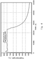
- Fig. 4 is a temperature chart of a temperature directly under the pedestal 21, i.e., a temperature of the powder bed during the shaping.
- a horizontal axis represents time and a vertical axis represents temperatures. As shown in Fig.
- the preheating temperature was maintained at about 800°C. That is, a microalloyed steel component to be shaped was maintained at about 800°C until the shaping was completed. After the completion of the shaping, the microalloyed steel component was cooled at a predetermined cooling rate.
- Fig. 5 show photographs of microstructures of microalloyed steel components according to examples.
- Fig. 5 shows Examples 1 and 2 including pearlite layers having different widths for a comparative therebetween.
- a sample had a prism shape having a cross section of 25 mm square. Further, an electric current of the electron beam was 20 mA and a scanning speed was 2,500 mm/s.
- a sample had a prism shape having a cross section of 10 mm square. Further, an electric current of the electron beam was 15 mA and a scanning speed was 2,500 mm/s.
- a fine columnar structure composed of band-shaped pearlite layers extending in the shaping direction and having a width of 100 to 200 ⁇ m, and ferrite layers linearly extending in the shaping direction between the pearlite layers was obtained.
- a fine columnar structure was observed in the microalloyed steel component according to the Example 2.
- a width of the pearlite layer was 50 to 150 ⁇ m. That is, a finer columnar structure was obtained. It is presumed that since the sample shape of the Example 2 was smaller than that of Example 1, the solidification speed of the Example 2 was increased.
- the volume of the microalloyed steel powder 30 melted by the electron beam EB is very small. Therefore, it is possible to control a structure of austenite, which is generated during the solidification, so as to have a fine columnar structure composed of crystalline grains extending in the shaping direction. Further, since this austenite is kept at a temperature higher than the austenite transformation completion temperature A3 by the preheating, the fine columnar austenitic structure is maintained until the completion of the shaping. In the cooling process after the completion of the shaping, ferrite is precipitated linearly along the original austenite grain boundaries.
- Fig. 6 is a schematic cross section showing relations between shaping directions (columnar structure growling directions) of the samples A, B and C, and longitudinal directions thereof.
- the shaping direction of the sample A was perpendicular to the longitudinal direction thereof.
- the shaping direction of the sample B was inclined from the longitudinal direction thereof by 45°.
- the shaping direction of the sample C coincided with the longitudinal direction thereof.
- SLM Selective Laser Melting
- Fig. 7 is a graph showing stress-strain curves in tensile tests of the samples A, B and C, and the SLM sample for comparisons thereof.
- a horizontal axis represents strains and a vertical axis represents stresses.
- Table 1 collectively shows tensile strengths and breaking elongations (i.e., elongations at breaking) of those samples.
- Sample A Sample B Sample C Sample SLM Tensile strength (MPa) 521.8 625.5 691.2 1155.5 Breaking elongation (%) 4.7 10.6 24.6 8.9
- Fig. 8 is a graph showing fatigue characteristics (S-N curves) of the samples A, B and C for comparisons thereof.
- a horizontal axis represents numbers of repetitions before the component was broken (i.e., raptured) and a vertical axis represents stresses. Arrows shown in the figure indicate that they were not broken.
- the sample C according to the example of the first embodiment exhibited the best fatigue characteristic.
- a fine columnar structure composed of band-shaped pearlite layers and ferrite layers precipitated between the pearlite layers extends in the longitudinal direction. Therefore, its mechanical properties such as a tensile strength, an elongation, and a fatigue characteristic are superior to those of the other samples.
Landscapes
- Engineering & Computer Science (AREA)
- Chemical & Material Sciences (AREA)
- Materials Engineering (AREA)
- Manufacturing & Machinery (AREA)
- Mechanical Engineering (AREA)
- Metallurgy (AREA)
- Organic Chemistry (AREA)
- Automation & Control Theory (AREA)
- Physics & Mathematics (AREA)
- Plasma & Fusion (AREA)
- Thermal Sciences (AREA)
- Crystallography & Structural Chemistry (AREA)
- Powder Metallurgy (AREA)
- Welding Or Cutting Using Electron Beams (AREA)
- Heat Treatment Of Articles (AREA)
Abstract
Description
- The present disclosure relates to a microalloyed steel component and a method for manufacturing the microalloyed steel component.
- As disclosed in Japanese Unexamined Patent Application Publication No.
2007-211314 - Incidentally, an additive manufacturing method has been recently attracting attention. In a powder-bed-fusion type additive manufacturing method, a metal component having a three-dimensional (3D) shape is fabricated in a layer-by-layer manner by selectively melting and solidifying a predetermined area in a metal powder layer by scanning laser or the like. In the additive manufacturing, the process to form the metal powder layers and the process to selectively melt and solidify the powder layer are repeated. By using the additive manufacturing method, it is also possible to manufacture a steel component which is designed so as to have a complicated shape by, for example, topology optimization for a weight reduction.
- If it is possible to control a structure of a microalloyed steel component so as to have a fine columnar structure composed of ferrite/pearlite extending in a predetermined direction, it could be possible to achieve excellent mechanical properties (such as a tensile strength and an elongation). However, as described above, microalloyed steel components manufactured by the conventional technique have isotropic structures. That is, a microalloyed steel component having a fine columnar structure extending in a predetermined direction has not been realized yet. Note that although a columnar structure can be obtained by a unidirectional solidification method, it cannot provide a fine columnar structure.
- The present inventors have focused on an additive manufacturing method, and diligently and repeatedly studied how to obtain a fine columnar structure composed of ferrite/pearlite extending in a predetermined direction. As a result, the present inventors have found the following problem.
- When a steel component made of microalloyed steel is shaped by using a selective laser melting method, a cooling rate (i.e., a cooling speed) is high. Therefore, the obtained structure becomes a martensitic structure, rather than becoming a ferrite/pearlite structure, and cracking is likely to occur. That is, in the selective laser melting method, a fine columnar structure composed of ferrite/pearlite extending in a predetermined direction was not obtained.
- The present disclosure has been made in view of the above-described circumstances and an object thereof is to provide a microalloyed steel component having a fine columnar structure composed of ferrite and pearlite extending in a predetermined direction, and thereby having excellent mechanical properties, and provide a method for manufacturing such microalloyed steel components.
- A first exemplary aspect is a microalloyed steel component including a structure composed of ferrite and pearlite, the microalloyed steel component including a columnar structure including:
- band-shaped pearlite layers extending in a longitudinal direction of the microalloyed steel component and having a width of 200 µm or shorter; and
- a ferrite layer precipitated so as to extend in the longitudinal direction between the pearlite layers.
- Since the microalloyed steel component according to an aspect of the present disclosure includes a fine columnar structure including: band-shaped pearlite layers extending in the longitudinal direction of the microalloyed steel component and having a width of 200 µm or shorter; and a ferrite layer precipitated between the pearlite layers, it has excellent mechanical properties.
- The microalloyed steel component may be topologically optimized. A weight can be reduced by the topology optimization. Further, a thin-walled part formed by the topology optimization has a finer columnar structure and hence mechanical properties are further improved.
- Another exemplary aspect is a microalloyed steel component manufacturing method for shaping a microalloyed steel component having a three-dimensional (3D) shape, including:
- spreading a microalloyed steel powder in a layered state;
- preheating the microalloyed steel powder spread in the layered state by applying an electron beam to the microalloyed steel powder; and
- forming a metal layer by applying an electron beam to a predetermined area of the preheated microalloyed steel powder, and thereby melting and solidifying the microalloyed steel powder in the predetermined area; and
- repeating the spreading, the preheating, and the forming, and thereby successively laminating metal layers, in which
- a shaping direction is in parallel with a longitudinal direction of the microalloyed steel component, and the microalloyed steel powder is heated to a temperature higher than an austenite transformation completion temperature A3 in the preheating, and
- after the shaping of the microalloyed steel component is completed, the microalloyed steel component is cooled from the temperature higher than the austenite transformation completion temperature A3 at a predetermined cooling rate.
- In the microalloyed steel component manufacturing method according to an aspect of the present disclosure, the shaping direction is in parallel with the longitudinal direction of the microalloyed steel component, and the microalloyed steel powder is heated to a temperature higher than the austenite transformation completion temperature A3 in the preheating. Therefore, it is possible to obtain a fine columnar structure composed of austenite extending in the shaping direction, i.e., in the longitudinal direction while maintaining an austenite single phase. Further, after the shaping of the microalloyed steel component is completed, the microalloyed steel component is cooled from the temperature higher than the austenite transformation completion temperature A3 at a predetermined cooling rate. Therefore, ferrite is precipitated in crystalline grain boundaries of fine columnar austenite formed during the shaping. Further, pearlite is precipitated so as to fill gaps of the precipitated ferrite. As a result, a microalloyed steel component having a fine columnar structure composed of ferrite/pearlite extending in the longitudinal direction, and thereby having excellent mechanical properties is obtained.
- The microalloyed steel component may be topologically optimized. A weight can be reduced by the topology optimization. Further, a thin-walled part formed by the topology optimization has a finer columnar structure and hence mechanical properties are further improved.
- According to the present disclosure, it is possible to provide a microalloyed steel component having a fine columnar structure composed of ferrite and pearlite extending in a predetermined direction, and thereby having excellent mechanical properties, and provide a method for manufacturing such microalloyed steel components.
- The above and other objects, features and advantages of the present disclosure will become more fully understood from the detailed description given hereinbelow and the accompanying drawings which are given by way of illustration only, and thus are not to be considered as limiting the present disclosure.
-
-
Fig. 1 is a schematic cross section showing an electron beam shaping apparatus used in a method for manufacturing a microalloyed steel component according to a first embodiment; -
Fig. 2 is a flowchart showing a method for manufacturing a microalloyed steel component according to a first embodiment; -
Fig. 3 is a plan view of a connecting rod for an automobile, which is an example of a microalloyed steel component according to a first embodiment; -
Fig. 4 is a temperature chart of a temperature directly under apedestal 21, i.e., a temperature of a powder bed during shaping; -
Fig. 5 show photographs of microstructures of microalloyed steel components according to examples; -
Fig. 6 is a schematic cross section showing relations between shaping directions of samples A, B and C, and longitudinal directions thereof; -
Fig. 7 is a graph showing stress-strain curves in tensile tests of the samples A, B and C, and an SLM sample for comparisons thereof; and -
Fig. 8 is a graph showing fatigue characteristics (S-N curves) of the samples A, B and C for comparisons thereof. - Specific embodiments to which the present disclosure is applied will be described hereinafter in detail with reference to the drawings. However, the present disclosure is not limited to the below-shown embodiments. Further, the following descriptions and drawings are simplified as appropriate for clarifying the explanation.
- Firstly, a manufacturing apparatus used for a method for manufacturing a microalloyed steel component according to a first embodiment is described with reference to
Fig. 1. Fig. 1 is a schematic cross section showing an electron beam shaping apparatus used in the method for manufacturing a microalloyed steel component according to the first embodiment. - Note that the microalloyed steel component in this specification means a steel component having the same composition as that of microalloyed steel. That is, whether a steel component is regarded as a microalloyed steel component or not is determined based solely on its composition. That is, its history of thermal processes and other factors are not taken into consideration.
- Further, needless to say, right-handed xyz orthogonal coordinate systems shown in
Fig. 1 and other drawings are shown for the sake of convenience to explain positional relations among components. In general, a z-axis positive direction is a vertically upward direction and an xy-plane is a horizontal plane. - As shown in
Fig. 1 , the electron beam shaping apparatus includes a cylindrical electronbeam gun chamber 10 extending in the z-axis direction, and a box-like shaping chamber 20 disposed below the electron beam gun chamber 10 (i.e., on the z-axis negative direction side of the electron beam gun chamber 10). The electronbeam gun chamber 10 and the shapingchamber 20 are evacuated by a vacuum exhausting apparatus (not shown). - As shown in
Fig. 1 , anelectron beam gun 11, afocus coil 12, and adeflection coil 13 are housed in the electronbeam gun chamber 10. Theelectron beam gun 11 is disposed above the electronbeam gun chamber 10, and an electron beam EB is emitted from theelectron beam gun 11 in a downward direction (i.e., in the z-axis negative direction). - The
focus coil 12 and thedeflection coil 13 are arranged so as to surround the electron beam EB. The electron beam EB emitted from theelectron beam gun 11 passes through thefocal coil 12, then passes through thedeflection coil 13, and is guided into the shapingchamber 20. The electron beam EB is scanned (i.e., is moved left and right, and/or up and down) by adjusting the focus of the electron beam EB by using thefocal coil 12 and deflecting the electron beam EB by using thedeflection coil 13. - As shown in
Fig. 1 , apedestal 21,hoppers rake 23 are housed in the shapingchamber 20. - The
pedestal 21 is a plate-like component having a rectangular shape on a plan view, and is disposed in a central part of the electronbeam gun chamber 10. Further, thepedestal 21 can be moved in the vertical direction. Thepedestal 21 is called a start plate, a platform, or the like. - The
hoppers pedestal 21 in the x-axis direction. - The
rake 23 is a rod-like component extending in the y-axis direction on thepedestal 21 and can be moved in the x-axis direction. Therake 23 is also called a squeegee or the like. - A
microalloyed steel powder 30, which is a raw material, is housed in thehopper - By moving the
rake 23 in the x-axis positive direction, themicroalloyed steel powder 30 supplied through a lower opening of thehopper 22a is spread in a layered state on thepedestal 21. After applying the electron beam EB to the spread microalloyedsteel powder 30, i.e., the powder bed and thereby preheating it to a predetermined temperature, a metal layer is formed by selectively applying an electron beam EB to a predetermined area(s) of the spread microalloyedsteel powder 30, and thereby melting and solidifying themicroalloyed steel powder 30 in the predetermined area(s). The thickness of the spread microalloyed steel powder 30 (hereinafter also referred to as the lamination thickness) is, for example, 50 to 80 µm. - Similarly, by moving the
rake 23 in the x-axis negative direction, themicroalloyed steel powder 30 supplied through a lower opening of thehopper 22b is spread in a layered state on thepedestal 21. After applying the electron beam EB to the spread microalloyedsteel powder 30 and thereby preheating it to a predetermined temperature, a metal layer is formed by selectively applying an electron beam EB to a predetermined area(s) of the spread microalloyedsteel powder 30, and thereby melting and solidifying themicroalloyed steel powder 30 in the predetermined area(s). - Specifically, a metal layer is formed by moving the
rake 23 in the x-axis positive direction and thereby spreading themicroalloyed steel powder 30 supplied from thehopper 22a. Then, thepedestal 21 is lowered. The distance by which thepedestal 21 is lowered is equal to the laminate thickness. Then, a metal layer is formed by moving therake 23 in the x-axis negative direction and thereby spreading themicroalloyed steel powder 30 supplied from thehopper 22b. Then, thepedestal 21 is lowered. As described above, themicroalloyed steel powder 30 is repeatedly supplied from thehoppers rake 23 is moved, themicroalloyed steel powder 30 can be spread on thepedestal 21, thus enabling excellent production efficiency. - As described above, in the electron beam shaping apparatus shown in
Fig. 1 , every time a metal layer is formed by irradiating the spread microalloyedsteel powder 30 with the electron beam EB, thepedestal 21 is lowered. By doing so, new metal layers are successively laminated. By the above-described configuration, amicroalloyed steel component 40 can be formed on thepedestal 21. - Next, a method for manufacturing a microalloyed steel component according to the first embodiment is described with reference to
Fig. 2. Fig. 2 is a flow chart showing a method for manufacturing a microalloyed steel component according to the first embodiment. In the following explanation related toFig. 2 ,Fig. 1 is also referred to as appropriate. - As shown in
Fig. 2 , firstly, amicroalloyed steel powder 30 supplied from the lower opening of thehopper microalloyed steel powder 30 is spread on thepedestal 21 for the first time, thepedestal 21 may be preheated to a predetermined temperature by irradiating thepedestal 21 with an electron beam EB before the step ST1. - Next, the spread microalloyed
steel powder 30 is preheated by applying an electron beam EB to it (step ST2). Note that themicroalloyed steel powder 30 is heated to a temperature higher than an austenite transformation completion temperature A3. Specifically, themicroalloyed steel powder 30 is heated to, for example, about 800°C. - Next, a metal layer is formed by applying an electron beam EB to a predetermined area(s) of the preheated
microalloyed steel powder 30, and thereby melting and solidifying themicroalloyed steel powder 30 in the predetermined area(s) (step ST3). - Then, when the shaping has not been completed yet (No at step ST4), the
pedestal 21 is lowered by a distance equivalent to the lamination thickness and the steps ST1 to ST3 are repeated. Then, when the shaping has been completed (Yes at step ST4), the shaping is finished. That is, the steps ST1 to ST3 are repeated until the shaping is completed. In this way, metal layers are successively laminated and amicroalloyed steel component 40 having a three-dimensional (3D) shape is thereby shaped. Then, after completing the shaping of themicroalloyed steel component 40, thismicroalloyed steel component 40 is cooled from the temperature higher than the austenite transformation completion temperature A3 at a predetermined cooling rate. - Note that in the method for manufacturing a microalloyed steel component according to the first embodiment, the shaping direction is in parallel with the longitudinal direction of the
microalloyed steel component 40. Note that, needless to say, a certain degree of a deviation between the longitudinal direction of themicroalloyed steel component 40 and the shaping direction is allowed. - In the method for manufacturing a microalloyed steel component according to the first embodiment, in the step ST2 in which the
microalloyed steel powder 30 is preheated, themicroalloyed steel powder 30 is heated to a temperature higher than the austenite transformation completion temperature A3. Therefore, it is possible to obtain a fine columnar structure composed of austenite extending in the shaping direction, i.e., in the longitudinal direction while maintaining an austenite single phase. Further, after the shaping of themicroalloyed steel component 40 is completed, themicroalloyed steel component 40 is cooled from the temperature higher than the austenite transformation completion temperature A3 at a predetermined cooling rate. Therefore, ferrite is precipitated in crystalline grain boundaries of fine-columnar austenite formed during the shaping. Further, pearlite is precipitated so as to fill gaps of the precipitated ferrite. As a result, a fine columnar structure composed of ferrite/pearlite extending in the longitudinal direction can be obtained. - The microalloyed steel component according to the first embodiment has a columnar structure composed of band-shaped pearlite layers extending in the shaping direction and having a width of 200 µm or shorter, and ferrite layers precipitated between the pearlite layers. Note that the shaping direction is in parallel with the longitudinal direction of the microalloyed steel component. As described above, the microalloyed steel component according to the first embodiment has a fine columnar structure composed of ferrite and pearlite extending in the longitudinal direction of the microalloyed steel component. Therefore, the microalloyed steel component has excellent mechanical properties such as a tensile strength, an elongation, and a fatigue characteristic. Details of the structure of the microalloyed steel component according to the first embodiment will be described later when examples are described.
- The microalloyed steel component according to the first embodiment is, for example, a connecting rod, a piston, a camshaft, or the like used in an automobile, though it is not limited to such components. These microalloyed steel components may be designed so as to have complicated shapes by, for example, topology optimization for weight reductions. Note that
Fig. 3 is a plan view of a connecting rod for an automobile, which is an example of the microalloyed steel component according to the first embodiment.Fig. 3 shows shapes before and after topology optimization. - As shown in
Fig. 3 , it is possible to shape even the complicated shape after the topology optimization by using the method for manufacturing a microalloyed steel component according to the first embodiment. As shown inFig. 3 , a thin-walled part is formed in the microalloyed steel component after the topology optimization. In the thin-walled part, a cooling rate increases and hence it is possible to make the columnar structure finer. Since the connecting rod shown inFig. 3 has a fine columnar structure composed of ferrite and pearlite both of which extend in the longitudinal direction, it has excellent mechanical properties such as a tensile strength, an elongation and a fatigue characteristic. - The microalloyed steel component and the method for manufacturing a microalloyed steel component according to the first embodiment are described hereinafter in detail by using comparative examples and examples. However, the microalloyed steel component and the method for manufacturing the same according to the first embodiment are not limited to the following examples.
- As the
microalloyed steel powder 30, one having constituents equivalent to those of a commercially-available microalloyed steel having a composition of Fe-0.45C-0.3Si-0.7Mn-0.003S-0.15Cr-0.1V, and a particle size (or a particle diameter) of 45 to 150 µm was used. As the electron beam shaping apparatus, an electron beam shaping apparatus A2X manufactured by Arcam EBM was used. The laminate thickness was 70 µm and the preheating temperature was about 800°C.Fig. 4 is a temperature chart of a temperature directly under thepedestal 21, i.e., a temperature of the powder bed during the shaping. A horizontal axis represents time and a vertical axis represents temperatures. As shown inFig. 4 , the preheating temperature was maintained at about 800°C. That is, a microalloyed steel component to be shaped was maintained at about 800°C until the shaping was completed. After the completion of the shaping, the microalloyed steel component was cooled at a predetermined cooling rate. -
Fig. 5 show photographs of microstructures of microalloyed steel components according to examples.Fig. 5 shows Examples 1 and 2 including pearlite layers having different widths for a comparative therebetween. In the Example 1, a sample had a prism shape having a cross section of 25 mm square. Further, an electric current of the electron beam was 20 mA and a scanning speed was 2,500 mm/s. In the Example 2, a sample had a prism shape having a cross section of 10 mm square. Further, an electric current of the electron beam was 15 mA and a scanning speed was 2,500 mm/s. - As shown in
Fig. 5 , in the microalloyed steel component according to the Example 1, a fine columnar structure composed of band-shaped pearlite layers extending in the shaping direction and having a width of 100 to 200 µm, and ferrite layers linearly extending in the shaping direction between the pearlite layers was obtained. Similarly, a fine columnar structure was observed in the microalloyed steel component according to the Example 2. In the Example 2, a width of the pearlite layer was 50 to 150 µm. That is, a finer columnar structure was obtained. It is presumed that since the sample shape of the Example 2 was smaller than that of Example 1, the solidification speed of the Example 2 was increased. - A reason why a fine columnar structure is obtained is described hereinafter. In the method for manufacturing a microalloyed steel component according to the first embodiment, the volume of the
microalloyed steel powder 30 melted by the electron beam EB is very small. Therefore, it is possible to control a structure of austenite, which is generated during the solidification, so as to have a fine columnar structure composed of crystalline grains extending in the shaping direction. Further, since this austenite is kept at a temperature higher than the austenite transformation completion temperature A3 by the preheating, the fine columnar austenitic structure is maintained until the completion of the shaping. In the cooling process after the completion of the shaping, ferrite is precipitated linearly along the original austenite grain boundaries. Further, pearlite is precipitated into the original austenite grains so as to fill the gaps of the precipitated ferrite. As a result, a fine columnar structure in which belt-shaped pearlite having a width of 200 µm or shorter, precipitated in the original austenite grains and ferrite lineally precipitated in the original austenite grain boundaries are alternately aligned (i.e., alternately arranged) is obtained. - In order to examine the effect of the direction in which the fine columnar structure extends on mechanical properties, three types of samples A, B and C in which directions in which columnar structures extend with respect to the longitudinal direction (the stress load direction) are different from each other were manufactured. Further, tensile tests and fatigue tests were carried out for them. Each of all the samples A, B and C had a prism shape having a cross section of 10 mm square. Further, an electric current of the electron beam was 16 mA and a scanning speed was 2,800 mm/s. The other conditions are similar to those of the structure observation test.
-
Fig. 6 is a schematic cross section showing relations between shaping directions (columnar structure growling directions) of the samples A, B and C, and longitudinal directions thereof. As shown inFig. 6 , the shaping direction of the sample A was perpendicular to the longitudinal direction thereof. The shaping direction of the sample B was inclined from the longitudinal direction thereof by 45°. The shaping direction of the sample C coincided with the longitudinal direction thereof. - Further, for a comparison purpose, a sample was manufactured by using a laser shaping (SLM: Selective Laser Melting) apparatus. (This sample is referred to as an SLM sample hereinafter). The SLM sample had a martensitic structure.
-
Fig. 7 is a graph showing stress-strain curves in tensile tests of the samples A, B and C, and the SLM sample for comparisons thereof. A horizontal axis represents strains and a vertical axis represents stresses. Further, Table 1 collectively shows tensile strengths and breaking elongations (i.e., elongations at breaking) of those samples.[Table 1] Sample A Sample B Sample C Sample SLM Tensile strength (MPa) 521.8 625.5 691.2 1155.5 Breaking elongation (%) 4.7 10.6 24.6 8.9 - As shown in
Fig. 7 and Table 1, since the SLM sample had the martensitic structure, it had a tensile strength larger than 1,100 MPa. However, its breaking elongation was so small that its tenacity was poor. - As shown in
Fig. 7 and Table 1, it was observed that mechanical properties of the samples A, B and C, which were manufactured by using the electron beam shaping apparatus, had significant dependences on the shaping directions (the columnar structure growing directions). Specifically, both the tensile strength and the breaking elongation were improved as the shaping direction was brought closer to the longitudinal direction of the shaped object, i.e., the microalloyed steel component. As described above, the sample C according to the example of the first embodiment exhibited excellent mechanical properties including a tensile strength of nearly 700 MPa and a breaking elongation exceeding 20%. The other samples B and C and the sample SLM are comparative examples of the first embodiment. -
Fig. 8 is a graph showing fatigue characteristics (S-N curves) of the samples A, B and C for comparisons thereof. A horizontal axis represents numbers of repetitions before the component was broken (i.e., raptured) and a vertical axis represents stresses. Arrows shown in the figure indicate that they were not broken. As shown inFig. 8 , the sample C according to the example of the first embodiment exhibited the best fatigue characteristic. - As described above, in the sample C according to the example of the first embodiment, a fine columnar structure composed of band-shaped pearlite layers and ferrite layers precipitated between the pearlite layers extends in the longitudinal direction. Therefore, its mechanical properties such as a tensile strength, an elongation, and a fatigue characteristic are superior to those of the other samples.
- From the disclosure thus described, it will be obvious that the embodiments of the disclosure may be varied in many ways. Such variations are not to be regarded as a departure from the spirit and scope of the disclosure, and all such modifications as would be obvious to one skilled in the art are intended for inclusion within the scope of the following claims.
Claims (4)
- A microalloyed steel component (40) comprising a structure composed of ferrite and pearlite, the microalloyed steel component comprising a columnar structure comprising:band-shaped pearlite layers extending in a longitudinal direction of the microalloyed steel component and having a width of 200 µm or shorter; anda ferrite layer precipitated so as to extend in the longitudinal direction between the pearlite layers.
- The microalloyed steel component (40) according to Claim 1, wherein the microalloyed steel component is topologically optimized.
- A microalloyed steel component manufacturing method for shaping a microalloyed steel component (40) having a three-dimensional (3D) shape, comprising:spreading a microalloyed steel powder (30) in a layered state;preheating the microalloyed steel powder (30) spread in the layered state by applying an electron beam (EB) to the microalloyed steel powder (30); andforming a metal layer by applying an electron beam (EB) to a predetermined area of the preheated microalloyed steel powder (30), and thereby melting and solidifying the microalloyed steel powder (30) in the predetermined area; andrepeating the spreading, the preheating, and the forming, and thereby successively laminating metal layers, whereina shaping direction is in parallel with a longitudinal direction of the microalloyed steel component, and the microalloyed steel powder (30) is heated to a temperature higher than an austenite transformation completion temperature A3 in the preheating, andafter the shaping of the microalloyed steel component (40) is completed, the microalloyed steel component (40) is cooled from the temperature higher than the austenite transformation completion temperature A3 at a predetermined cooling rate.
- The microalloyed steel component manufacturing method according to Claim 3, wherein the microalloyed steel component is topologically optimized.
Applications Claiming Priority (1)
| Application Number | Priority Date | Filing Date | Title |
|---|---|---|---|
| JP2018096987A JP7032234B2 (en) | 2018-05-21 | 2018-05-21 | Non-microalloyed steel member and its manufacturing method |
Publications (1)
| Publication Number | Publication Date |
|---|---|
| EP3572167A1 true EP3572167A1 (en) | 2019-11-27 |
Family
ID=66286119
Family Applications (1)
| Application Number | Title | Priority Date | Filing Date |
|---|---|---|---|
| EP19170911.2A Withdrawn EP3572167A1 (en) | 2018-05-21 | 2019-04-24 | Microalloyed steel component and manufacturing method therefor |
Country Status (4)
| Country | Link |
|---|---|
| US (1) | US20190352730A1 (en) |
| EP (1) | EP3572167A1 (en) |
| JP (1) | JP7032234B2 (en) |
| CN (1) | CN110508808B (en) |
Families Citing this family (6)
| Publication number | Priority date | Publication date | Assignee | Title |
|---|---|---|---|---|
| JP2021188078A (en) * | 2020-05-27 | 2021-12-13 | 三菱電機株式会社 | Three-dimensional molding apparatus, and method of producing three-dimensional molding article |
| CN112210707B (en) * | 2020-08-11 | 2022-03-29 | 大连理工大学 | Method for preparing high-performance high-speed steel by electron beam melting |
| CN112818483B (en) * | 2021-01-25 | 2023-10-03 | 江苏徐工工程机械研究院有限公司 | Design and manufacturing method of hydraulic valve block based on selective laser melting |
| IT202100020180A1 (en) * | 2021-07-28 | 2021-10-28 | Morphica S R L | Dust regulation device |
| MX2024010061A (en) | 2022-02-16 | 2024-08-26 | Jfe Steel Corp | Deposition model and method for producing same. |
| KR20240116495A (en) | 2022-02-16 | 2024-07-29 | 제이에프이 스틸 가부시키가이샤 | Laminated sculpture and its manufacturing method |
Citations (3)
| Publication number | Priority date | Publication date | Assignee | Title |
|---|---|---|---|---|
| JP2007211314A (en) | 2006-02-10 | 2007-08-23 | Sumitomo Metal Ind Ltd | Hot forging method for non-tempered parts |
| US20080075618A1 (en) * | 2006-09-19 | 2008-03-27 | Schlumberger Technology Corporation | Metal Powder Layered Apparatus for Downhole Use |
| CN107587076A (en) * | 2017-09-19 | 2018-01-16 | 北京科技大学 | The production method of bent axle major diameter ferrite+pearlite type non-hardened and tempered steel bar |
Family Cites Families (9)
| Publication number | Priority date | Publication date | Assignee | Title |
|---|---|---|---|---|
| JPS5573845A (en) * | 1978-11-27 | 1980-06-03 | Nisshin Steel Co Ltd | Eliminating method for band structure of hot rolled low alloy steel plate |
| JPS63243250A (en) * | 1987-03-31 | 1988-10-11 | Sumitomo Metal Ind Ltd | Manufacture of high-strength sintered steel |
| JP2000108246A (en) * | 1998-10-09 | 2000-04-18 | Sanyo Special Steel Co Ltd | Cladding material with high impact resistance even after heat treatment and its processed parts |
| JP4121416B2 (en) * | 2002-04-26 | 2008-07-23 | Jfe条鋼株式会社 | Non-tempered hot forged parts for machine structure and manufacturing method thereof |
| JP2008261046A (en) * | 2007-03-19 | 2008-10-30 | Kobe Steel Ltd | High-tensile steel excellent in weldability and plastic deformability, and cold-formed steel pipe formed therefrom |
| EP2878409B2 (en) * | 2013-11-27 | 2022-12-21 | SLM Solutions Group AG | Method of and device for controlling an irradiation system |
| US10610930B2 (en) * | 2015-11-18 | 2020-04-07 | Arcam Ab | Additive manufacturing of three-dimensional articles |
| JP2017186653A (en) * | 2016-03-31 | 2017-10-12 | 三菱電機株式会社 | Three-dimensional shaped object and manufacturing method thereof |
| CN109554618A (en) * | 2017-09-26 | 2019-04-02 | 陕西汽车集团有限责任公司 | Non-hardened and tempered steel and the method that automobile axle shaft is manufactured using non-hardened and tempered steel |
-
2018
- 2018-05-21 JP JP2018096987A patent/JP7032234B2/en not_active Expired - Fee Related
-
2019
- 2019-04-18 US US16/388,085 patent/US20190352730A1/en not_active Abandoned
- 2019-04-24 EP EP19170911.2A patent/EP3572167A1/en not_active Withdrawn
- 2019-05-17 CN CN201910410813.0A patent/CN110508808B/en not_active Expired - Fee Related
Patent Citations (3)
| Publication number | Priority date | Publication date | Assignee | Title |
|---|---|---|---|---|
| JP2007211314A (en) | 2006-02-10 | 2007-08-23 | Sumitomo Metal Ind Ltd | Hot forging method for non-tempered parts |
| US20080075618A1 (en) * | 2006-09-19 | 2008-03-27 | Schlumberger Technology Corporation | Metal Powder Layered Apparatus for Downhole Use |
| CN107587076A (en) * | 2017-09-19 | 2018-01-16 | 北京科技大学 | The production method of bent axle major diameter ferrite+pearlite type non-hardened and tempered steel bar |
Non-Patent Citations (3)
| Title |
|---|
| C. KÖRNER: "Additive manufacturing of metallic components by selective electron beam melting - a review", INTERNATIONAL MATERIALS REVIEWS, vol. 61, no. 5, 9 May 2016 (2016-05-09), US, pages 361 - 377, XP055624304, ISSN: 0950-6608, DOI: 10.1080/09506608.2016.1176289 * |
| ERDEN MEHMET AKIF ET AL: "Microstructural characterization and mechanical properties of microalloyed powder metallurgy steels", MATERIALS SCIENCE, ELSEVIER, AMSTERDAM, NL, vol. 616, 17 August 2014 (2014-08-17), pages 201 - 206, XP029063642, ISSN: 0921-5093, DOI: 10.1016/J.MSEA.2014.08.026 * |
| OLSÉN JON ET AL: "Micro- and macro-structural heterogeneities in 316L stainless steel prepared by electron-beam melting", MATERIALS CHARACTERIZATION, ELSEVIER, NEW YORK, NY, US, vol. 141, 18 April 2018 (2018-04-18), pages 1 - 7, XP085403996, ISSN: 1044-5803, DOI: 10.1016/J.MATCHAR.2018.04.026 * |
Also Published As
| Publication number | Publication date |
|---|---|
| US20190352730A1 (en) | 2019-11-21 |
| CN110508808B (en) | 2022-03-01 |
| JP2019203148A (en) | 2019-11-28 |
| CN110508808A (en) | 2019-11-29 |
| JP7032234B2 (en) | 2022-03-08 |
Similar Documents
| Publication | Publication Date | Title |
|---|---|---|
| US20190352730A1 (en) | Microalloyed steel component and manufacturing method therefor | |
| KR102855094B1 (en) | Method for manufacturing aluminum alloy parts | |
| US10232602B2 (en) | Method and apparatus for producing three-dimensional objects with improved properties | |
| CN111699063B (en) | Method of making aluminum-chromium alloy parts | |
| CN104511589B (en) | Method for producing a metal component by additive laser production | |
| CN111954725A (en) | Additive layer-manufactured hot-work mold, method of making the same, and metal powder for additive-layer-manufactured hot-work mold | |
| US8329092B2 (en) | Metal powder for metal laser-sintering and metal laser-sintering process using the same | |
| EP3449025B1 (en) | Bcc materials of titanium, aluminum, vanadium, and iron, and products made therefrom | |
| CN102905821A (en) | Metal powder for powder sintering lamination, method for producing three-dimensional shaped article using same, and obtained three-dimensional shaped article | |
| CN112191845A (en) | Hot processing method for improving structural uniformity of additive manufacturing nickel-based superalloy | |
| JP7028791B2 (en) | BCC materials for titanium, aluminum, niobium, vanadium, and molybdenum, and the products produced from them. | |
| US20220126367A1 (en) | Process for manufacturing an aluminum alloy part | |
| KR20190041729A (en) | Hardfacing method of press die | |
| KR20240014505A (en) | Aluminum alloy part manufacturing method that implements additive manufacturing using preheating | |
| US20240043974A1 (en) | Shaped Article Produced From Powder | |
| CN114054773A (en) | Preparation method of laminated heterogeneous aluminum alloy sheet with non-uniform distribution of precipitates | |
| CN117444241A (en) | A method for controlling the heterostructure of aluminum alloys with alternating fine and coarse grain structure characteristics | |
| CN117265420A (en) | Maraging steel and its additive manufacturing method | |
| CN119426621A (en) | A method for preparing high-strength and low-thermal expansion Invar alloy by laser cladding and high-strength and low-thermal expansion Invar alloy | |
| US20210331247A1 (en) | Method of producing additively manufactured object and additively manufactured object | |
| US12037664B2 (en) | Iron alloy manufacturing method | |
| US20260091428A1 (en) | Iron-Based Alloy Powder and Method for Producing Molded Body | |
| CN116904783A (en) | Method for simultaneously improving strength and conductivity of CuCrZr alloy manufactured by additive | |
| KR102944239B1 (en) | Method for manufacturing and designing composite three-dimensional magnetic shielding elements, shielding elements, and uses thereof | |
| EP4344804A1 (en) | Highly conductive aluminium alloy |
Legal Events
| Date | Code | Title | Description |
|---|---|---|---|
| PUAI | Public reference made under article 153(3) epc to a published international application that has entered the european phase |
Free format text: ORIGINAL CODE: 0009012 |
|
| STAA | Information on the status of an ep patent application or granted ep patent |
Free format text: STATUS: REQUEST FOR EXAMINATION WAS MADE |
|
| 17P | Request for examination filed |
Effective date: 20190424 |
|
| AK | Designated contracting states |
Kind code of ref document: A1 Designated state(s): AL AT BE BG CH CY CZ DE DK EE ES FI FR GB GR HR HU IE IS IT LI LT LU LV MC MK MT NL NO PL PT RO RS SE SI SK SM TR |
|
| AX | Request for extension of the european patent |
Extension state: BA ME |
|
| STAA | Information on the status of an ep patent application or granted ep patent |
Free format text: STATUS: EXAMINATION IS IN PROGRESS |
|
| 17Q | First examination report despatched |
Effective date: 20220902 |
|
| STAA | Information on the status of an ep patent application or granted ep patent |
Free format text: STATUS: THE APPLICATION HAS BEEN WITHDRAWN |
|
| 18W | Application withdrawn |
Effective date: 20221028 |