EP3572127A2 - Fire extinguishing system and method therefor - Google Patents
Fire extinguishing system and method therefor Download PDFInfo
- Publication number
- EP3572127A2 EP3572127A2 EP19173759.2A EP19173759A EP3572127A2 EP 3572127 A2 EP3572127 A2 EP 3572127A2 EP 19173759 A EP19173759 A EP 19173759A EP 3572127 A2 EP3572127 A2 EP 3572127A2
- Authority
- EP
- European Patent Office
- Prior art keywords
- fire extinguishing
- extinguishing agent
- fluid stream
- stream separating
- separating device
- Prior art date
- Legal status (The legal status is an assumption and is not a legal conclusion. Google has not performed a legal analysis and makes no representation as to the accuracy of the status listed.)
- Pending
Links
Images





Classifications
-
- A—HUMAN NECESSITIES
- A62—LIFE-SAVING; FIRE-FIGHTING
- A62C—FIRE-FIGHTING
- A62C31/00—Delivery of fire-extinguishing material
- A62C31/02—Nozzles specially adapted for fire-extinguishing
- A62C31/03—Nozzles specially adapted for fire-extinguishing adjustable, e.g. from spray to jet or vice versa
-
- A—HUMAN NECESSITIES
- A62—LIFE-SAVING; FIRE-FIGHTING
- A62C—FIRE-FIGHTING
- A62C35/00—Permanently-installed equipment
- A62C35/58—Pipe-line systems
- A62C35/68—Details, e.g. of pipes or valve systems
-
- A—HUMAN NECESSITIES
- A62—LIFE-SAVING; FIRE-FIGHTING
- A62C—FIRE-FIGHTING
- A62C3/00—Fire prevention, containment or extinguishing specially adapted for particular objects or places
- A62C3/07—Fire prevention, containment or extinguishing specially adapted for particular objects or places in vehicles, e.g. in road vehicles
- A62C3/08—Fire prevention, containment or extinguishing specially adapted for particular objects or places in vehicles, e.g. in road vehicles in aircraft
-
- A—HUMAN NECESSITIES
- A62—LIFE-SAVING; FIRE-FIGHTING
- A62C—FIRE-FIGHTING
- A62C31/00—Delivery of fire-extinguishing material
- A62C31/005—Delivery of fire-extinguishing material using nozzles
-
- A—HUMAN NECESSITIES
- A62—LIFE-SAVING; FIRE-FIGHTING
- A62C—FIRE-FIGHTING
- A62C31/00—Delivery of fire-extinguishing material
- A62C31/02—Nozzles specially adapted for fire-extinguishing
- A62C31/05—Nozzles specially adapted for fire-extinguishing with two or more outlets
-
- A—HUMAN NECESSITIES
- A62—LIFE-SAVING; FIRE-FIGHTING
- A62C—FIRE-FIGHTING
- A62C31/00—Delivery of fire-extinguishing material
- A62C31/28—Accessories for delivery devices, e.g. supports
-
- A—HUMAN NECESSITIES
- A62—LIFE-SAVING; FIRE-FIGHTING
- A62C—FIRE-FIGHTING
- A62C99/00—Subject matter not provided for in other groups of this subclass
- A62C99/0009—Methods of extinguishing or preventing the spread of fire by cooling down or suffocating the flames
- A62C99/0018—Methods of extinguishing or preventing the spread of fire by cooling down or suffocating the flames using gases or vapours that do not support combustion, e.g. steam, carbon dioxide
-
- F—MECHANICAL ENGINEERING; LIGHTING; HEATING; WEAPONS; BLASTING
- F25—REFRIGERATION OR COOLING; COMBINED HEATING AND REFRIGERATION SYSTEMS; HEAT PUMP SYSTEMS; MANUFACTURE OR STORAGE OF ICE; LIQUEFACTION SOLIDIFICATION OF GASES
- F25B—REFRIGERATION MACHINES, PLANTS OR SYSTEMS; COMBINED HEATING AND REFRIGERATION SYSTEMS; HEAT PUMP SYSTEMS
- F25B9/00—Compression machines, plants or systems, in which the refrigerant is air or other gas of low boiling point
- F25B9/02—Compression machines, plants or systems, in which the refrigerant is air or other gas of low boiling point using Joule-Thompson effect; using vortex effect
- F25B9/04—Compression machines, plants or systems, in which the refrigerant is air or other gas of low boiling point using Joule-Thompson effect; using vortex effect using vortex effect
Definitions
- the exemplary embodiments generally relate to fire extinguishing systems and more particularly to fire extinguishing systems employing vortex tubes to increase cold environment performance of a fire extinguishing agent.
- the passive heating of the fire extinguishing agent 250 is performed mechanically with a fluid stream separating device 290 (such as a vortex tube 260, also known as a Ranque-Hilsch vortex tube) that utilizes no moving or electrical parts and is powered by a fluid flow 600 ( Fig. 6 ), of the fire extinguishing agent 250, passing through the device.
- a fluid stream separating device 290 such as a vortex tube 260, also known as a Ranque-Hilsch vortex tube
- the kinetic energy of the fluid flow 600 e.g., which is a high speed fluid flow
- passing through the vortex tube 260 is transformed into thermal energy which raises the temperature of at least a portion of the fluid flow, resulting in a hot peripheral fluid flow vortex 600HV ( Fig. 6 ) and a cold axial fluid flow vortex 600CV ( Fig.
- a "cold bottle” refers to the fluid storage container 210A, 210B having a fire extinguishing agent 250 at a temperature of about -65°F (54°C) to about the boiling point of the fire extinguishing agent 250.
- a “cold compartment” refers to compartment 115 having a temperature therein of about -65°F (54°C) to about the boiling point of the fire extinguishing agent 250.
- very cold refers to a temperature below about -65°F (54°C).
- the term “warm” refers to a temperature above the boiling point of the fire extinguishing agent 250.
- the utilization of the at least one remote discharge nozzle 501, 502 may provide placement of the at least one remote discharge nozzle 501, 502 in spaces that the one or more fluid stream separating devices 290 may not fit.
- the utilization of the at least one remote discharge nozzle 501, 502 may also provide for a greater separation distance between the first discharge 603 and the second discharge 604.
- Each of the at least one remote discharge nozzle 501, 502 may be disposed at a fire extinguishing agent discharge location (such as one or more of fire extinguishing agent discharge locations 301, 302, 303) in lieu of the associated one or more fluid stream separating devices 290. While remote discharge nozzles 501, 502 are shown coupled to a respective one of the integral discharge nozzle 601, 602; in other aspects remote discharge nozzle(s) 501, 502 may be coupled to only one of the integral discharge nozzles 601, 602.
Landscapes
- Health & Medical Sciences (AREA)
- Public Health (AREA)
- Business, Economics & Management (AREA)
- Emergency Management (AREA)
- Engineering & Computer Science (AREA)
- Physics & Mathematics (AREA)
- Mechanical Engineering (AREA)
- Thermal Sciences (AREA)
- General Engineering & Computer Science (AREA)
- Fire-Extinguishing By Fire Departments, And Fire-Extinguishing Equipment And Control Thereof (AREA)
Abstract
Description
- The exemplary embodiments generally relate to fire extinguishing systems and more particularly to fire extinguishing systems employing vortex tubes to increase cold environment performance of a fire extinguishing agent.
- Generally, commercial airplane fire extinguishing systems use Halon 1301 as a fire extinguishing agent. At the present time, Halon 1301 is being phased out of all industry use for environmental reasons. Halon 1301 has a boiling temperature of about -71°F (-57°C). Alternative fire extinguishing agents are being explored as a replacement for Halon 1301; however, the alternative fire extinguishing agents may have a higher boiling temperature than Halon 1301. The higher boiling temperature of the alternative fire extinguishing agents may impact the performance of these fire extinguishing agents in cold temperature environments that have temperatures that are at or below the boiling temperature of the respective fire extinguishing agents.
- Accordingly, apparatuses and methods, intended to address at least one or more of the above-identified concerns, would find utility.
- The following is a non-exhaustive list of examples, which may or may not be claimed, of the subject matter according to the present disclosure.
- One example of the subject matter according to the present disclosure relates to a fire extinguishing system including a fluid storage container configured to store a fire extinguishing agent, and a fluid stream separating device coupled to the fluid storage container, where the fire extinguishing agent passes from the fluid storage container through the fluid stream separating device so that the fluid stream separating device raises a temperature of at least a portion of the fire extinguishing agent flowing through the fluid stream separating device above a boiling point of the fire extinguishing agent at ambient environmental conditions of a discharge location of the fluid stream separating device.
- Another example of the subject matter according to the present disclosure relates to a fire extinguishing system for a vehicle having an engine, the fire extinguishing system including a fluid storage container configured to store a fire extinguishing agent; and a fluid stream separating device coupled to the fluid storage container, the fluid stream separating device being configured to mechanically separate the fire extinguishing agent flowing through the fluid stream separating device into a hot discharge component and a cold discharge component, where the hot discharge component has a temperature above a boiling point of the fire extinguishing agent at ambient environmental conditions of a discharge location of the fluid stream separating device.
- Still another example of the subject matter according to the present disclosure relates to a method of using a fire extinguishing system, the method including storing a fire extinguishing agent in a fluid storage container; and mechanically separating, with a fluid stream separating device coupled to the fluid storage container, the fire extinguishing agent flowing through the fluid stream separating device into a hot discharge component and a cold discharge component, where the hot discharge component has a temperature above a boiling point of the fire extinguishing agent at ambient environmental conditions of a discharge location of the fluid stream separating device.
- Having thus described examples of the present disclosure in general terms, reference will now be made to the accompanying drawings, which are not necessarily drawn to scale, and wherein like reference characters designate the same or similar parts throughout the several views, and wherein:
-
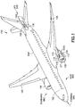
Fig. 1 is a schematic isometric illustration of an aircraft in accordance with aspects of the present disclosure; -
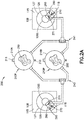
Fig. 2A is a schematic diagram illustration of an exemplary fire extinguishing system in accordance with aspects of the present disclosure; -
Fig. 2B is a schematic diagram illustration of an exemplary fire extinguishing system in accordance with aspects of the present disclosure; -
Fig. 3A is a schematic isometric illustration of a portion of the aircraft (e.g., an engine) ofFig. 1 in accordance with aspects of the present disclosure; -
Fig. 3B is an exemplary isometric cut-away illustration of a portion of the engine ofFig. 3A in accordance with aspects of the present disclosure; -
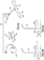
Fig. 4A is a schematic illustration of a portion of the fire extinguishing system of either one ofFigs. 2A and2B in accordance with aspects of the present disclosure; -
Fig. 4B and 4C are exemplary illustrations of fluid stream separating devices of the fire extinguishing system of either one ofFigs. 2A and2B in accordance with aspects of the present disclosure; -
Fig. 5 is an exemplary illustration of a fluid stream separating device of the fire extinguishing system of either one ofFigs. 2A and2B in accordance with aspects of the present disclosure; -
Fig. 6A is an exemplary illustration of a fluid stream separating device of the fire extinguishing system of either one ofFigs. 2A and2B in accordance with aspects of the present disclosure; -
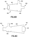
Fig. 6B is an exemplary illustration of a fluid stream separating device of the fire extinguishing system of either one ofFigs. 2A and2B in accordance with aspects of the present disclosure; -
Fig. 6C is an exemplary illustration of a fluid stream separating device of the fire extinguishing system of either one ofFigs. 2A and2B in accordance with aspects of the present disclosure; -
Fig. 7 is an exemplary flow diagram of a method in accordance with aspects of the present disclosure; -
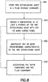
Fig. 8 is an exemplary flow diagram of a method in accordance with aspects of the present disclosure; and -
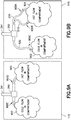
Figs. 9A and 9B are schematic illustrations showing exemplary exit planes of a fire extinguishing system in accordance with aspects of the present disclosure. - Referring to
Figs. 1 ,2A and2B , the aspects of the present disclosure may provide for a fire extinguishingsystem 200 for use in environments having ambient temperatures at or below a boiling point of afire extinguishing agent 250 used therein. The aspects of the present disclosure may be integrated into new vehicles or retrofit into existing vehicles by installing the aspects of the present disclosure to existing fire extinguishing system manifolds. The fire extinguishingsystem 200 described herein may provide ambient condition operation, including cold environment operation, of the fire extinguishingsystem 200, where the cold environment operation includes temperatures near or below a boiling point of afire extinguishing agent 250 used in the fire extinguishingsystem 200. As used herein, the term "boiling point" refers to the boiling point of thefire extinguishing agent 250 when thefire extinguishing agent 250 exits the fire extinguishing system 200 (at anexit plane 900A-900E, seeFigs. 9A and 9B ) and enters, for example, engine compartment 115 (or other suitable compartment) and is exposed to ambient conditions. Although the temperature within at least a portion of the fire extinguishingsystem 200 may be substantially same as an ambient temperature, the pressures and velocities of thefire extinguishing agent 250 may be sufficient enough, within the portion of the fire extinguishingsystem 200 to drive thefire extinguishing agent 250 into a liquid state within the portion of the fire extinguishingsystem 200. - The fire extinguishing
system 200 mechanically increases the temperature of the fire extinguishing agent to a temperature above the boiling point of thefire extinguishing agent 250. For example, the fire extinguishingsystem 200 may provide for cold environment operation down to temperatures as low as about -65°F (54°C) or lower. Examples of fire extinguishing agents that may be used in the fire extinguishingsystem 200 include any suitable fire extinguishing agent (or mixtures thereof) such as, but not limited to, Halon 1301 (having a boiling point of about -71°F or about -57°C), HFC-125 (pentafluoroethane, having a boiling point of about -55°F or about -48°C), CF3I (trifluoroiodomethane, having a boiling point of about -9°F or about -23°C), Novec™ 1230 (manufactured by 3M™, having a boiling point of about 120°F or about 49°C), and sodium bicarbonate (NaHCO3). - The fire extinguishing
system 200 employs afire extinguishing agent 250 that is stored in a liquid form within a pressurizedfluid storage container 210P. The pressurizedfluid storage container 210P is configured to store thefire extinguishing agent 250 at pressures of about 100 psi to about 300 psi, or up to pressures of about 500 psi or greater. The fire extinguishingsystem 200 passively heats thefire extinguishing agent 250 as thefire extinguishing agent 250 is expelled from the fire extinguishingsystem 200, so that the liquidfire extinguishing agent 250 is vaporized and dispersed for extinguishing a fire. The passive heating of thefire extinguishing agent 250 is performed mechanically with a fluid stream separating device 290 (such as avortex tube 260, also known as a Ranque-Hilsch vortex tube) that utilizes no moving or electrical parts and is powered by a fluid flow 600 (Fig. 6 ), of thefire extinguishing agent 250, passing through the device. The kinetic energy of the fluid flow 600 (e.g., which is a high speed fluid flow) passing through thevortex tube 260 is transformed into thermal energy which raises the temperature of at least a portion of the fluid flow, resulting in a hot peripheral fluid flow vortex 600HV (Fig. 6 ) and a cold axial fluid flow vortex 600CV (Fig. 6 ) within thevortex tube 260. The aspects of the present disclosure utilize the mechanical separation of thefire extinguishing agent 250 into ahot discharge component 250H (Fig. 6 ) and acold discharge component 250C (Fig. 6 ) (where thehot discharge component 250H has a hotter temperature than thecold discharge component 250C) to cool hot surfaces and extinguish fires. The mechanical separation of thefire extinguishing agent 250 increases a temperature of thehot discharge component 250H to effect, in some aspects (see "Table 1" below), vaporization of the fire extinguishing agent in the cold environment (e.g., at ambient temperatures as low as about -65°F (54°C) or lower). As described below with respect to Table 1, thehot discharge component 250H and thecold discharge component 250C may be in either a liquid or vapor state. - Illustrative, non-exhaustive examples, which may or may not be claimed, of the subject matter according to the present disclosure are provided below.
- In accordance with aspects of the present disclosure, the
fire extinguishing system 200 may be used in any suitable application such as, for example, in dwellings, on vehicles (e.g., terrestrial, maritime, submersibles, aerospace, etc.), in outdoor environments, and in commercial or industrial (indoor or outdoor) environments. For ease of illustration, the aspects of the present disclosure will be described with respect tovehicle 100 illustrated inFig. 1 . Thevehicle 100 is illustrated as a fixed wing aircraft but may be any suitable vehicle as noted above. Thevehicle 100 includesfuselage 102 having aframe 100F,wings 106, andengines 108. Theengines 108 are coupled to thewings 106 by apylon 110 and include anacelle 112. Eachnacelle 112 forms anengine compartment 115 in which afan 127 and acore 126 of arespective engine 108 are located. One or more fire zones 118 (e.g., predetermined areas, seeFigs. 1 ,2A and3B ) are disposed within theengine compartment 115, where eachfire zone 118 has one or more discharge(s) (integral discharge and/or remote discharge) of thefire extinguishing system 200 disposed therein. Thevehicle 100 may also include anauxiliary power unit 135 disposed within an auxiliarypower unit compartment 130 of thevehicle 100. Theauxiliary power unit 135 may be any suitable on-board engine for generating auxiliary power for aircraft component (e.g., electric systems, hydraulic systems, ventilation systems, etc.) consumption while theengines 108 are not operating. - Referring to
Fig. 2A , thefire extinguishing system 200 includes afluid storage container stream separating devices 290. While twofluid storage containers Fig. 2A more or less than twofluid storage containers fluid storage container fire extinguishing agent 250 in any suitable manner. For example, thefluid storage container pressurized storage 210P that stores thefire extinguishing agent 250 as a cryogenic or non-cryogenic fluid (depending on characteristics, such as the boiling temperature, of thefire extinguishing agent 250 being used). Thefluid storage container suitable fluid inlet 211 andpressure relief 212 for filling thefluid storage container fire extinguishing agent 250 and to relieve excess pressure from thefluid storage container - The one or more fluid
stream separating devices 290 are coupled to thefluid storage container stream separating devices 290 to thefluid storage container fire extinguishing agent 250 passes from thefluid storage container stream separating devices 290. In one aspect, the one or more fluidstream separating devices 290 respectively comprise avortex tube 260. Here, the one or more fluidstream separating devices 290 are configured so that thefire extinguishing agent 250 passes through a respective fluidstream separating device 290 and the respective fluidstream separating device 290 raises a temperature of at least a portion 610 (Fig. 6 ) of thefire extinguishing agent 250 flowing through the respective fluidstream separating device 290 substantially at or above the boiling point of thefire extinguishing agent 250. Theportion 610 of thefire extinguishing agent 250 that is above the boiling point may be discharged from the respectivefluid separating device 290 as a vapor or liquid while another portion 611 (Fig. 6A ) of thefire extinguishing agent 250 that is below the boiling point of thefire extinguishing agent 250 is discharged from the respectivefluid separating device 290 as a vapor or liquid. Table 1A, Table 1B, and Table 1C (collectively referred to as Table 1) below illustrate the state (i.e., vapor or liquid) of thefire extinguishing agent 250 at various locations of the fluidstream separating device 290, including at exits (e.g., at arespective exit plane 900A-900E, seeFigs. 9A and 9B of thehot exit aperture 620 and the cold exit aperture 650) of thefire extinguishing system 200 to the ambient environment; however it should be understood that Table 1 is not an exhaustive list of possible states.TABLE 1A Location Inlet 662 Hot Exit Aperture 620 Hot Flow Nozzle Exit Plane 900A, 900B, 900D Hot Flow 901 in Engine Compartment 115 at Ambient Conditions Cold Exit Aperture 650 Cold Flow Nozzle Exit Plane 900C, 900E Cold Flow 902 in Engine Compartment 115 at Ambient Conditions Expected environmental conditions (about -65F) with expected performance end state Liquid Liquid Liquid Vapor Vapor Vapor Liquid Cold Bottle/Cold Compartment Liquid Liquid Vapor Vapor Vapor Vapor Liquid Cold Bottle/Warm Compartment Liquid Liquid Vapor Vapor Vapor Vapor Vapor TABLE 1B Location Inlet 662 Hot Exit Aperture 620 Hot Flow Nozzle Exit Plane 900A, 900B, 900D Hot Flow 901 in Engine Compartment 115 at Ambient Conditions Cold Exit Aperture 650 Cold Flow Nozzle Exit Plane 900C, 900E Cold Flow 902 in Engine Compartment 115 at Ambient Conditions Very cold bottle (hot exit aperture 620 below boiling point) Liquid Liquid Liquid Liquid Liquid Liquid Liquid Hot exit aperture 620 below boiling point Liquid Liquid Liquid Liquid Vapor Vapor Liquid Hot exit aperture 620 below boiling point (cold vapor condenses in exit tube) Liquid Liquid Liquid Liquid Vapor Liquid Liquid Cold exit aperture 650 and Hot exit aperture 620 above boiling point, warm bottle discharge Vapor Vapor Vapor Vapor Vapor Vapor Vapor TABLE 1C Location Inlet 662 Hot Exit Aperture 620 Hot Flow Nozzle Exit Plane 900A, 900B, 900D Hot Flow 901 in Engine Compartment 115 at Ambient Conditions Cold Exit Aperture 650 Cold Flow Nozzle Exit Plane 900C, 900E Cold Flow 902 in Engine Compartmen t 115 at Ambient Conditions Hot exit aperture 620 above boiling point, cold exit aperture 650 below boiling point/condenses in exit tube, warm bottle discharge Vapor Vapor Vapor Vapor Vapor Liquid Liquid - In Table 1, a "cold bottle" refers to the
fluid storage container fire extinguishing agent 250 at a temperature of about -65°F (54°C) to about the boiling point of thefire extinguishing agent 250. A "cold compartment" refers tocompartment 115 having a temperature therein of about -65°F (54°C) to about the boiling point of thefire extinguishing agent 250. The term "very cold" refers to a temperature below about -65°F (54°C). The term "warm" refers to a temperature above the boiling point of thefire extinguishing agent 250. As an example, with respect to Table 1, where theengine compartment 115 and thefluid storage container hot exit aperture 620 will be above the boiling point of thefire extinguishing agent 250 at the ambient conditions of the point of use (e.g., such as in the engine compartment 115) so as to be in a vapor state within theengine compartment 115; while the cold axial fluid flow vortex 600CV, at thecold exit aperture 650 will be below the boiling point of thefire extinguishing agent 250 so as to be in a liquid state within theengine compartment 115, due to energy extraction from the cold axial fluid flow vortex 600CV to the hot peripheral fluid flow vortex 600HV. - Referring to
Figs. 1 and2A , thefire extinguishing system 200 is configured for the application offire extinguishing agent 250 to one or more of theengines 108 of thevehicle 100. InFig. 2A , the one or more fluidstream separating devices 290 are disposed within each of the engine compartments 115. The one or more fluidstream separating devices 290 are positioned to discharge the portion 610 (Fig. 6 ) of thefire extinguishing agent 250 that is above the boiling point, so that thefire extinguishing agent 250 is in the form of avapor 270, into an air flow 300 (Fig. 3A ) internal to the one or more fire zone 118 (Fig. 3A ) passing through/around theengine 108, through theengine compartment 115, for extinguishing a fire. In one aspect, the one or more fluidstream separating devices 290 are positioned to discharge the portion 610 (Fig. 6 ) of thefire extinguishing agent 250 that is above the boiling point (e.g., as as avapor 270 in the engine compartment 115) into the air flow 300 (Fig. 3A ) in a direction that is perpendicular to the air flow 300 (Fig. 3A ); while in other aspects, the fluidstream separating devices 290 are positioned to discharge the portion 610 (Fig. 6 ) of thefire extinguishing agent 250 at any suitable angle relative to the air flow 300 (Fig. 3A ). In one aspect, the one or more fluidstream separating devices 290 are also positioned to discharge the other portion 611 (Fig. 6 ) of thefire extinguishing agent 250 that is below the boiling point as a liquid 271 onto a surface to be cooled, such as asurface 126S of thecore 126; while in other aspects theother portion 611 may be directed to any suitable portion of theengine 108. - For example, referring to
Figs. 3A and 3B , theengine 108 on the starboard side of the vehicle is illustrated for exemplary purposes only. The one or more fluidstream separating devices 290 may be disposed within the engine compartment 115 (such as in fire zone 118) adjacent the forward side of theengine 108 and one or more fluidstream separating devices 290 may be disposed within theengine compartment 115 adjacent the aft side of theengine 108. The one or more fluidstream separating devices 290 are illustrated inFig. 3B as being disposed on the port side of theengine 108 but it should be understood that the one or more fluidstream separating devices 290 may also be placed on the starboard side of theengine 108 as well. Each of the one or more fluidstream separating devices 290 is disposed adjacent the engine 108 (or auxiliary power unit 135) at a respective fire extinguishingagent discharge location integral discharge nozzle 601, 602 (Figs. 6A ,6B, 6C ) to discharge thefire extinguishing agent 250 at the fire extinguishingagent discharge location integral discharge nozzle 601, 602 (Figs. 6A ,6B, 6C ) includes a first discharge 603 (Fig. 6A ) and a second discharge 604 (Fig. 6A ). - In other aspects, as can be seen in
Fig. 5 , at least oneremote discharge nozzle stream separating devices 290 in any suitable manner. For example, anysuitable conduit remote discharge nozzle integral discharge nozzle 601, 602 (Fig. 6 ) of the one or more fluidstream separating devices 290. One or more (seeFig. 4A ) of the at least oneremote discharge nozzle 501 is coupled to the one or more fluidstream separating devices 290 to discharge thefire extinguishing agent 250 in a vapor form, and one or more other (seeFig. 4A ) of the at least oneremote discharge nozzle 502 is coupled to the one or more fluidstream separating devices 290 to discharge thefire extinguishing agent 250 in a liquid form. Here, the utilization of the at least oneremote discharge nozzle remote discharge nozzle stream separating devices 290 may not fit. The utilization of the at least oneremote discharge nozzle first discharge 603 and thesecond discharge 604. Each of the at least oneremote discharge nozzle agent discharge locations stream separating devices 290. Whileremote discharge nozzles integral discharge nozzle integral discharge nozzles - Referring to
Figs. 1 and2B , thefire extinguishing system 200 may be configured for the application offire extinguishing agent 250 to the auxiliary power unit 135 (or any other suitable feature and/or area) of thevehicle 100. For example, inFig. 2B , one or more fluidstream separating devices 290 are disposed within the auxiliarypower unit compartment 130. Here, the one or more fluidstream separating devices 290 are positioned to discharge the portion 610 (Fig. 6 ) of thefire extinguishing agent 250 that is above the boiling point as avapor 270 into the auxiliarypower unit compartment 130 for extinguishing a fire. The one or more fluidstream separating devices 290 are also positioned to discharge the other portion 611 (Fig. 6 ) of thefire extinguishing agent 250 that is below the boiling point as a liquid 271 onto a surface to be cooled, such as asurface 135S of theauxiliary power unit 135. The one or more fluidstream separation devices 290 may be disposed within the auxiliarypower unit compartment 130 in a manner substantially similar to that described herein with respect to theengine compartment 115. - Referring to
Figs. 2A and4A , theconduits stream separating devices 290 to thefluid storage containers conduit 241 illustrated inFig. 4A for exemplary purposes only (conduit 240 may be similarly configured), theconduit 241 includes one ormore branch lines stream separating devices 290 may be coupled. As an example, thebranch lines engine 108 so thatbranch line 401 extends to the forward port side (Fig. 3B ) of the engine and thebranch line 400 extends to the forward starboard side (Fig. 3B ) of theengine 108. Thebranch lines engine 108 around (e.g., starboard side, port side, underneath, and/or above) thecore 126. - Referring to
Figs. 4B, 4C ,6A ,6B, and 6C , at least one of the one or more fluidstream separating devices 290 are constructed of any suitable material configured to withstand the pressures (e.g.,inlet 662 pressures of greater than about 100 psi) and temperatures at which the one or more fluidstream separating devices 290 are operated. For example, the one of the one or more fluidstream separating devices 290 may be constructed of steel, titanium, etc. The at least one of the one or more fluidstream separating devices 290 are also configured for one or more of manual and automatic manipulation of one or more predetermined characteristics of thefire extinguishing agent 250 flowing through the at least one of the one or more fluidstream separating devices 290. The predetermined characteristics include, but are not limited to, a temperature of thefire extinguishing agent 250, a mass flow of thefire extinguishing agent 250, and liquid and vapor mass states of thefire extinguishing agent 250. For example, as described herein, the fluidstream separating devices 290 comprisevortex tubes 260. Each vortex tube includes avortex chamber portion 660 and atube portion 661. Aninlet 662 extends from thevortex chamber portion 660 and is configured to couple thevortex tube 260 to aconduit 240, 241 (see alsoFig. 2A ). As described above, thevortex tube 260 includes an integral (hot)discharge nozzle 601 at thefirst discharge 603 and another integral (cold)discharge nozzle 602 at thesecond discharge 604. Each fluidstream separating device 290 is configured to mechanically separate thefire extinguishing agent 250 flowing through the fluidstream separating device 290 into thehot discharge component 250H and thecold discharge component 250C, where thehot discharge component 250H has a temperature above the boiling point of thefire extinguishing agent 250. The fluidstream separating device 290 is configured to increase the temperature of thehot discharge component 250H to above the boiling point through a conservation of enthalpy as thefire extinguishing agent 250 is being discharged from the fire extinguishing system 200 (Figs. 2A and2B ). - The integral (hot) discharge nozzle 601 (or a remote discharge nozzle(s) coupled thereto) discharges the
hot discharge component 250H into theengine compartment 115 so that thehot discharge component 250H is in one of vapor state or a liquid state as noted above with respect to Table 1. The integral (hot)discharge nozzle 601 includes ahot exit aperture 620, the size of which is determined by afirst throttle valve 621. Thefirst throttle valve 621 is, in one aspect, a fixedvalve 621F where the size of thehot exit aperture 620 is set and does not change. In other aspects, thefirst throttle valve 621 may be anadjustable valve 621A, such as a butterfly valve 621A1, a ball valve 621A2 or an adjustable plug valve (substantially similar in shape to the fixedvalve 621F but axially moveable in and out of the tube portion 661). Theadjustable valve 621A may be driven in any suitable manner such as manually or automatically by a firstvalve throttling drive 622. The firstvalve throttling drive 622 may include one or more of adrive motor 623, shape memory alloy (SMA)members 624 or any other suitable actuator for throttling thefirst throttle valve 621 and changing a size of thehot exit aperture 620. Acontroller 630 may be coupled to the vortex tube 260 (e.g., to the first valve throttling drive 622) and include any suitable non-transitory computer program code and structure (e.g., processors, memory, etc.) for operating thefirst throttle valve 621 to change a size of thehot exit aperture 620, depending on, for example, environmental conditions in which the fire extinguishing system 200 (Figs. 2A ,2B ) operates. Thecontroller 630 may be configured to operate thefirst throttle valve 621 based on sensor 631 signals where the sensor senses the environmental conditions and/or under control of a human operator and/or other command data. - The integral (cold) discharge nozzle 602 (or a remote discharge nozzle(s) coupled thereto) discharges the
cold discharge component 250C into theengine compartment 115 so that thecold discharge component 250C is in one of a vapor or liquid state within thecompartment 115 as noted above in Table 1. Similarly, the integral (cold)discharge nozzle 602 may include asecond throttle valve 640 that is substantially similar to the first throttle valve 621 (e.g., at least from the standpoint of being either fixed or adjustable) for setting or adjusting a size of acold exit aperture 650 of the integral (cold)discharge nozzle 602. Where thesecond throttle valve 640 is adjustable, thesecond throttle valve 640 may be automatically driven by a secondvalve throttling drive 642 in a manner similar to that described above with respect to the first valve throttling drive 622 (where thecontroller 630 is configured to operate thesecond throttle valve 640 in the manner described above). - Where at least of the
first throttle valve 621 and thesecond throttle valve 640 are fixed, the at least onefixed valve portion 610 of thefire extinguishing agent 250 flowing through the respective fluidstream separating device 290 above the boiling point of thefire extinguishing agent 250 and theother portion 611 of thefire extinguishing agent 250 flowing through the respective fluidstream separating device 290 below the boiling point of thefire extinguishing agent 250. Where at least of thefirst throttle valve 621 and thesecond throttle valve 640 are movable/adjustable, theadjustable valve hot exit aperture 620 andcold exit aperture 650 of the respective fluidstream separating device 290 to vary a temperature difference and/or a mass flow between theportion 610 of thefire extinguishing agent 250 flowing through the respective fluidstream separating device 290 above the boiling point of thefire extinguishing agent 250 and theother portion 611 of thefire extinguishing agent 250 flowing through the respective fluidstream separating device 290 below the boiling point of thefire extinguishing agent 250. - Referring to
Fig. 6A , as noted herein, the fluid stream separating device is configured to manipulate any suitable characteristic of thefire extinguishing agent 250 such as those described above. As an example, the temperature of thefire extinguishing agent 250, the mass flow of thefire extinguishing agent 250, and the liquid and vapor mass states of thefire extinguishing agent 250, may be manipulated (e.g., raised/increased or lowered/decreased) by one or more of increasing or decreasing one or more of the lengths L1, L2 of thetube portion 661 of the fluidstream separating device 290. For example, increasing at least the length L1 of thetube portion 661 may provide for increased interaction between the hot peripheral fluid flow vortex 600HV and the cold axial fluid flow vortex 600CV so that as the length L1 increases more heat is extracted from the cold axial fluid flow vortex 600CV by the hot peripheral fluid flow vortex 600HV to increase a temperature of theportion 610 of thefire extinguishing agent 250 exiting the hot exit aperture 620 (and decrease a temperature of theportion 611 of thefire extinguishing agent 250 exiting the cold exit aperture 650). As an example a length L1 to diameter D ratio of thetube portion 661 is in one aspect, about 20:1, but in other aspects the length L1 to diameter D ratio may be more or less than about 20:1. - Decreasing or increasing the size of the hot exit aperture 620 (and/or the cold exit aperture 650) also manipulates the temperature of the
portions fire extinguishing agent 250 exiting thehot exit aperture 620 and thecold exit aperture 650. For example, the smaller the hot exit aperture 620 (or the larger the cold exit aperture 650), the hotter the temperature of theportion 610 of thefire extinguishing agent 250 exiting thehot exit aperture 620 and vice versa. As noted above, the aperture sizes of thehot exit aperture 620 and/orcold exit aperture 650 may be fixed (e.g., not movable/adjustable) while in other aspects the aperture sizes are movable so as to be automatically or manually adjustable. The hotter theportion 610 of thefire extinguishing agent 250 exiting thehot exit aperture 620, the greater the vaporization and spreading of the fire extinguishing agent into the air flow (300 (Fig. 3A ) through, for example, theengine 108 or into the auxiliary power unit compartment 130 (Fig. 2B ). - Increasing or decreasing a size of at least the
hot exit aperture 620 also manipulates the liquid and vapor mass states (i.e., the coldmass fraction percentage 683 offire extinguishing agent 250 flowing through the fluid stream separating device 290) andmass flow 600F of the fire extinguishing agent flowing through the fluidstream separating device 290. For example, the larger the size of the hot exit aperture 620 (or the smaller the size of the cold exit aperture 650), the greater mass flow 600FH of theportion 610 of thefire extinguishing agent 250 exiting the hot exit aperture (with a corresponding decrease in mass flow 600FC of theportion 611 of thefire extinguishing agent 250 exiting thecold exit aperture 650 and decrease in temperature of theportion 610 exiting the hot exit aperture 620) and vice versa. As another example, the greater the cold mass fraction percentage 683 (i.e., the percentage of theportion 611 compared to theportion 610 flowing through the fluidstream separation device 290 as determined by the exit aperture sizes), the greater the temperature difference between thefire extinguishing agent 250 fluid flow at thehot exit aperture 620 and thecold exit aperture 650 of the fluid stream separating device. For example, a cold mass fraction of about 0.8 (e.g., 80%) may produce about a 140°F (60°C) temperature difference between thefire extinguishing agent 250 discharged from thehot exit aperture 620 and thefire extinguishing agent 250 discharged from thecold exit aperture 650 at aninlet 662 pressure of about 120 psi. - Where the size of one or more of the
hot exit aperture 620 and thecold exit aperture 650 are adjustable, as noted above, one or more of the above-described predetermined characteristics of thefire extinguishing agent 250 may be adjusted depending on the environment in which the fluid stream separating device is disposed. For example, where the engine compartment 115 (Fig. 2A ) and/or the auxiliary power unit compartment 130 (Fig. 2B ) are cold-soaked (e.g., exposed to ambient conditions such that the compartment and equipment no longer contain any residual heat from operation), one or more of thefirst throttle valve 621 and thesecond throttle valve 640 may be driven by the respective firstvalve throttling drive 622 and secondvalve throttling drive 642 so that a size of the respectivehot exit aperture 620 andcold exit aperture 650 is adjusted to provide an effective concentration/spread and performance of the fire extinguishing agent at the cold-soaked ambient conditions. - As can also be seen in
Figs. 6B and 6C , one or more of the integral (hot)discharge nozzle 601 and the integral (cold)discharge nozzle 602 may be a converging nozzle (Fig. 6B ). The converging nozzle(s) may increase the flow rate of thefire extinguishing agent 250 exiting (Fig. 6A ) there through (for sub-sonic fluid flows) which may increase dispersion of thefire extinguishing agent 250 by propelling the fire extinguishing agent further into the air flow 300 (Fig. 3A ) or further into the engine compartment 115 (Fig. 2A ) and/or the auxiliary power unit compartment 130 (Fig. 2B ). The diverging nozzle(s) may slow down the flow rate of thefire extinguishing agent 250 exiting (Fig. 6A ) there through (for sub-sonic fluid flows) which may increase dispersion of thefire extinguishing agent 250 by widening/broadening the stream of fire extinguishing agent over a predetermined target area and/or volume. - Referring now to
Figs. 1 ,2A ,2B ,6A and7 , a method of using thefire extinguishing system 200 will be described. Afire extinguishing agent 250 is stored in afluid storage container Fig. 7 , Block 700). Thefire extinguishing agent 250 flowing through the fluidstream separating device 290 is mechanically separated, by the fluidstream separating device 290, into ahot discharge component 250H and acold discharge component 250C, where at least a portion ofthe_hot discharge component 250H has a temperature above a boiling point of the fire extinguishing agent 250 (Fig. 7 , Block 710). In one aspect, one or more one or more predetermined characteristics of thefire extinguishing agent 250 flowing through the one or more fluidstream separating devices 290 is manually or automatically manipulated with the one or more fluid stream separating devices 290 (Fig. 7 , Block 720). For example, a temperature of thefire extinguishing agent 250 flowing through the one or more fluidstream separating devices 290 may be increased or decreased as described herein. For example, the temperature of thehot discharge component 250H may be increased to above the boiling point of thefire extinguishing agent 250 through a conservation of enthalpy as thefire extinguishing agent 250 is being discharged from thefire extinguishing system 200. A mass flow of thefire extinguishing agent 250 flowing through the one or more fluidstream separating devices 290 may be increased or decreased as described herein. Liquid and vapor mass states of thefire extinguishing agent 250 flowing through the one or more fluidstream separating devices 290 may be increased or decreased as described herein. - The
hot discharge component 250H and thecold discharge component 250C of thefire extinguishing agent 250 are discharged (Fig. 7 , Block 730) through arespective discharge nozzle stream separating device 290. Thefire extinguishing agent 250 is discharged at a fire extinguishingagent discharge location Fig. 3B ) with at least oneintegral discharge nozzle 601, 602 (or through aremote discharge nozzle 501, 502 -Fig. 5 ) of a respective fluidstream separating device 290. For example, thehot discharge component 250H of thefire extinguishing agent 250, that is above the boiling point, is discharged as a vapor or liquid according to Table 1 above (i.e., the first discharge 603) into an air flow 300 (Fig. 3A ) within afire zone 118 of anengine 108 for extinguishing a fire. Thecold discharge component 250C of thefire extinguishing agent 250, that is below the boiling point, is discharged as a liquid or a vapor according to Table 1 above (i.e., the second discharge 604) onto asurface 126S of the engine 108 (e.g., or any other suitable heat source(s)) to be cooled where the liquid may be presented as a mist (e.g., liquid droplets with some atomization) in the direction of the suitable heat source(s), where the mist is vaporized (as noted above in Table 1) adjacent the heat source(s). - Referring now to
Figs. 1 ,2A ,2B ,6A and8 , a method of using thefire extinguishing system 200 will be described. Thefire extinguishing agent 250 is stored in afluid storage container Fig. 8 , Block 800). A temperature of at least aportion 610 of thefire extinguishing agent 250 flowing through the one ormore vortex tubes 260 is raised, with the one or more vortex tubes coupled to the fluid storage container, above a boiling point of the fire extinguishing agent 250 (Fig. 8 , Block 810). In one aspect, one or more one or more predetermined characteristics of thefire extinguishing agent 250 flowing through the one or more fluidstream separating devices 290 is manually or automatically manipulated with the one or more fluid stream separating devices 290 (Fig. 8 , Block 820). For example, a temperature of thefire extinguishing agent 250 flowing through the one or more fluidstream separating devices 290 may be increased or decreased as described herein. For example, the temperature of thehot discharge component 250H may be increased to above the boiling point of thefire extinguishing agent 250 through a conservation of enthalpy as thefire extinguishing agent 250 is being discharged from thefire extinguishing system 200. A mass flow of thefire extinguishing agent 250 flowing through the one or more fluidstream separating devices 290 may be increased or decreased as described herein. Liquid and vapor mass states of thefire extinguishing agent 250 flowing through the one or more fluidstream separating devices 290 may be increased or decreased as described herein; noting that the total mass flow through the fluidstream separating device 290 is conserved between thefluid inlet 211 and the combination of both discharge nozzles (e.g., the integral hot andcold discharge nozzles cold exit apertures 620, 650). - The
hot discharge component 250H and thecold discharge component 250C of thefire extinguishing agent 250 are discharged (Fig. 7 , Block 830) through a respectiveintegral discharge nozzle 601, 602 (or remote discharge nozzle - seeFig. 5 ) coupled to the fluidstream separating device 290. Thefire extinguishing agent 250 is discharged at a fire extinguishingagent discharge location Fig. 3B ) within arespective fire zone 118 with at least oneintegral discharge nozzle 601, 602 (or through aremote discharge nozzle 501, 502 -Fig. 5 ) of a respective fluidstream separating device 290. For example, thehot discharge component 250H of thefire extinguishing agent 250, that is above the boiling point, is discharged into an air flow 300 (Fig. 3A ) within afire zone 118 of anengine 108 for extinguishing a fire. Thecold discharge component 250C of thefire extinguishing agent 250, that is below the boiling point, is discharged as a liquid or a vapor according to Table 1 above onto asurface 126S of theengine 108 to be cooled. - The following examples are provided in accordance with the aspects of the present disclosure:
- A1. A fire extinguishing system comprising:
- a fluid storage container configured to store a fire extinguishing agent; and
- a vortex tube coupled to the fluid storage container, where the fire extinguishing agent passes from the fluid storage container through the vortex tube so that the vortex tube raises a temperature of at least a portion of the fire extinguishing agent flowing through the vortex tube above a boiling point of the fire extinguishing agent at ambient environmental conditions of a discharge location of the vortex tube.
- A2. The fire extinguishing system of paragraph A1, wherein the vortex tube is disposed at a fire extinguishing agent discharge location and includes at least one integral discharge nozzle to discharge the fire extinguishing agent at the fire extinguishing agent discharge location.
- A3. The fire extinguishing system of paragraph A2, wherein the at least one integral discharge nozzle includes one or more of a vapor discharge and a liquid discharge.
- A4. The fire extinguishing system of any one of paragraphs A1-A3, further comprising at least one remote discharge nozzle coupled to the vortex tube, each of the at least one remote discharge nozzle being disposed at a fire extinguishing agent discharge location.
- A5. The fire extinguishing system of paragraph A4, wherein:
- one of the at least one remote discharge nozzle is coupled to the vortex tube to discharge a hot discharge component of the fire extinguishing agent in one of a vapor form and a liquid form, and
- another of the at least one remote discharge nozzle is coupled to the vortex tube to discharge a cold discharge component of the fire extinguishing agent in one of a vapor form and a liquid form.
- A6. The fire extinguishing system of any one of paragraphs A1-A5, wherein the vortex tube is positioned to:
- discharge the portion of the fire extinguishing agent that is above the boiling point as one of a vapor and a liquid into an air flow for extinguishing a fire, and
- discharge another portion of the fire extinguishing agent that is below the boiling point as one of a vapor and a liquid onto a surface to be cooled.
- A7. The fire extinguishing system of any one of paragraphs A1-A6, wherein the fluid storage container comprises a pressurized storage.
- A8. The fire extinguishing system of any one of paragraphs A1-A7, wherein the vortex tube includes at least one fixed valve that defines a temperature difference between the portion of the fire extinguishing agent flowing through the vortex tube above the boiling point of the fire extinguishing agent and another portion of the fire extinguishing agent flowing through the vortex tube below the boiling point of the fire extinguishing agent.
- A9. The fire extinguishing system of any one of paragraphs A1-A8, wherein the vortex tube includes at least one movable valve that varies an outlet size of the vortex tube to vary a temperature difference between the portion of the fire extinguishing agent flowing through the vortex tube above the boiling point of the fire extinguishing agent and another portion of the fire extinguishing agent flowing through the vortex tube below the boiling point of the fire extinguishing agent.
- A10. The fire extinguishing system of any one of paragraphs A1-A9, wherein the vortex tube is configured for manual manipulation of one or more predetermined characteristics of the fire extinguishing agent flowing through the vortex tube.
- A11. The fire extinguishing system of any one of paragraphs A1-A10, wherein the vortex tube is configured for automatic manipulation of one or more predetermined characteristics of the fire extinguishing agent flowing through the vortex tube.
- A12. The fire extinguishing system of any one of paragraphs A1-A11, wherein the vortex tube is configured to manipulate a temperature of the fire extinguishing agent flowing through the vortex tube.
- A13. The fire extinguishing system of any one of paragraphs A1-A12, wherein the vortex tube is configured to manipulate a mass flow of the fire extinguishing agent flowing through the vortex tube.
- A14. The fire extinguishing system of any one of paragraphs A1-A13, wherein the vortex tube is configured to manipulate liquid and vapor mass states of the fire extinguishing agent flowing through the vortex tube.
- A15. The fire extinguishing system of any one of paragraphs A1-A14, wherein the vortex tube is one of a plurality of vortex tubes coupled to the fluid storage container.
- B1. A fire extinguishing system for a vehicle having an engine, the fire extinguishing system comprising:
- a fluid storage container configured to store a fire extinguishing agent; and
- a fluid stream separating device coupled to the fluid storage container, the fluid stream separating device being configured to mechanically separate the fire extinguishing agent flowing through the fluid stream separating device into hot discharge component and a cold discharge component, where the hot discharge component has a temperature above a boiling point of the fire extinguishing agent at ambient environmental conditions of a discharge location of the fluid stream separating device.
- B2. The fire extinguishing system of paragraph B1, wherein the fluid stream separating device is configured to increase the temperature of at least a portion of the hot discharge component to above the boiling point through a conservation of enthalpy as the fire extinguishing agent is being discharged from the fire extinguishing system.
- B3. The fire extinguishing system of any one of paragraphs B1-B2, wherein the fluid stream separating device comprises a vortex tube.
- B4. The fire extinguishing system of paragraph B3, wherein the vortex tube includes at least one fixed valve that defines a temperature difference between the hot discharge component of the fire extinguishing agent flowing through the vortex tube above the boiling point and the cold discharge component of the fire extinguishing agent flowing through the vortex tube below the boiling point of the fire extinguishing agent.
- B5. The fire extinguishing system of paragraph B3, wherein the vortex tube includes at least one movable valve that varies an outlet size of the vortex tube to vary a temperature difference between the hot discharge component of the fire extinguishing agent flowing through the vortex tube above the boiling point of the fire extinguishing agent and the cold discharge component of the fire extinguishing agent flowing through the vortex tube below the boiling point of the fire extinguishing agent.
- B6. The fire extinguishing system of any one of paragraphs B1-B5, wherein the fluid stream separating device is disposed adjacent the engine at a fire extinguishing agent discharge location, the fluid stream separating device includes at least one integral discharge nozzle to discharge the fire extinguishing agent at the fire extinguishing agent discharge location.
- B7. The fire extinguishing system of paragraph B6, wherein the at least one integral discharge nozzle includes one or more of a vapor discharge and a liquid discharge.
- B8. The fire extinguishing system of any one of paragraphs B1-B7, further comprising at least one remote discharge nozzle coupled to the fluid stream separating device, each of the at least one remote discharge nozzle being disposed adjacent the engine at a fire extinguishing agent discharge location.
- B9. The fire extinguishing system of paragraph B8, wherein:
- one of the at least one remote discharge nozzle is coupled to the fluid stream separating device to discharge one of the hot discharge component and the cold discharge component of the fire extinguishing agent, and
- another of the at least one remote discharge nozzle is coupled to the fluid stream separating device to discharge another of the hot discharge component and the cold discharge component of the fire extinguishing agent.
- B10. The fire extinguishing system of any one of paragraphs B1-B9, wherein the fluid stream separating device is positioned to:
- discharge the hot discharge component of the fire extinguishing agent that is above the boiling point as one of a vapor and a liquid into an air flow adjacent the engine for extinguishing a fire, and
- discharge the cold discharge component of the fire extinguishing agent that is below the boiling point as one of a vapor and a liquid onto a surface of the engine to be cooled.
- B11. The fire extinguishing system of any one of paragraphs B1-B10, wherein the fluid storage container comprises a pressurized storage.
- B12. The fire extinguishing system of any one of paragraphs B1-B11, wherein the fluid stream separating device is configured for manual manipulation of one or more predetermined characteristics of the fire extinguishing agent flowing through the fluid stream separating device.
- B13. The fire extinguishing system of any one of paragraphs B1-B12, wherein the fluid stream separating device is configured for automatic manipulation of one or more predetermined characteristics of the fire extinguishing agent flowing through the fluid stream separating device.
- B14. The fire extinguishing system of any one of paragraphs B1-B14, wherein the fluid stream separating device is configured to manipulate a temperature of the fire extinguishing agent flowing through the fluid stream separating device.
- B15. The fire extinguishing system of any one of paragraphs B1-B14, wherein the fluid stream separating device is configured to manipulate a mass flow of the fire extinguishing agent flowing through the fluid stream separating device.
- B16. The fire extinguishing system of any one of paragraphs B1-B15, wherein the fluid stream separating device is configured to manipulate liquid and vapor mass states of the fire extinguishing agent flowing through the fluid stream separating device.
- C1. A fire extinguishing system comprising:
- a fluid storage container configured to store a fire extinguishing agent; and
- a fluid stream separating device coupled to the fluid storage container, where the fire extinguishing agent passes from the fluid storage container through the fluid stream separating device so that the fluid stream separating device raises a temperature of at least a portion of the fire extinguishing agent flowing through the fluid stream separating device above a boiling point of the fire extinguishing agent at ambient environmental conditions of a discharge location of the fluid stream separating device.
- C2. The fire extinguishing system of paragraph C1, wherein the fluid stream separating device is disposed at a fire extinguishing agent discharge location and includes at least one integral discharge nozzle to discharge the fire extinguishing agent at the fire extinguishing agent discharge location.
- C3. The fire extinguishing system of paragraph C2, wherein the at least one integral discharge nozzle includes one or more of a vapor discharge and a liquid discharge.
- C4. The fire extinguishing system of any one of paragraphs C1-C3, further comprising at least one remote discharge nozzle coupled to the fluid stream separating device, each of the at least one discharge nozzle being disposed at a fire extinguishing agent discharge location.
- C5. The fire extinguishing system of paragraph C4, wherein:
- one of the at least one remote discharge nozzle is coupled to the fluid stream separating device to discharge a hot discharge component of the fire extinguishing agent in one of a vapor form and a liquid form, and
- another of the at least one remote discharge nozzle is coupled to the fluid stream separating device to discharge a cold discharge component of the fire extinguishing agent in one of a vapor form and a liquid form.
- C6. The fire extinguishing system of any one of paragraphs C1-C5, wherein the fluid stream separating device is positioned to:
- discharge the portion of the fire extinguishing agent that is above the boiling point as one of a vapor and a liquid into an air flow for extinguishing a fire, and
- discharge another portion of the fire extinguishing agent that is below the boiling point as one of a vapor and a liquid onto a surface to be cooled.
- C7. The fire extinguishing system of any one of paragraphs C1-C6, wherein the fluid storage container comprises a pressurized storage.
- C8. The fire extinguishing system of paragraph C1-C7, wherein the fluid stream separating device includes at least one fixed valve that defines a temperature difference between the portion of the fire extinguishing agent flowing through the fluid stream separating device above the boiling point of the fire extinguishing agent and another portion of the fire extinguishing agent flowing through the fluid stream separating device below the boiling point of the fire extinguishing agent.
- C9. The fire extinguishing system of any one of paragraphs C1-C8, wherein the fluid stream separating device includes at least one movable valve that varies an outlet size of the fluid stream separating device to vary a temperature difference between the portion of the fire extinguishing agent flowing through the fluid stream separating device above the boiling point of the fire extinguishing agent and another portion of the fire extinguishing agent flowing through the fluid stream separating device below the boiling point of the fire extinguishing agent.
- C10. The fire extinguishing system of any one of paragraphs C1-C9, wherein the fluid stream separating device is configured to mechanically separate the fire extinguishing agent flowing through the fluid stream separating device into a vapor component and a liquid component, where the vapor component has a temperature above the boiling point of the fire extinguishing agent.
- C11. The fire extinguishing system of any one of paragraphs C1-C10, wherein the fluid stream separating device is configured for manual manipulation of one or more predetermined characteristics of the fire extinguishing agent flowing through the fluid stream separating device.
- C12. The fire extinguishing system of any one of paragraphs C1-C11, wherein the fluid stream separating device is configured for automatic manipulation of one or more predetermined characteristics of the fire extinguishing agent flowing through the fluid stream separating device.
- C13. The fire extinguishing system of any one of paragraphs C1-C12, wherein the fluid stream separating device is configured to manipulate a temperature of the fire extinguishing agent flowing through the fluid stream separating device.
- C14. The fire extinguishing system of any one of paragraphs C1-C13, wherein the fluid stream separating device is configured to manipulate a mass flow of the fire extinguishing agent flowing through the fluid stream separating device.
- C15. The fire extinguishing system of any one of paragraphs C1-C14, wherein the fluid stream separating device is configured to manipulate liquid and vapor mass states of the fire extinguishing agent flowing through the fluid stream separating device.
- C16. The fire extinguishing system of any one of paragraphs C1-C15, wherein the fluid stream separating device comprises a vortex tube.
- C17. The fire extinguishing system of any one of paragraphs C1-C16, wherein the fluid stream separating device is one of a plurality of fluid stream separating devices coupled to the fluid storage container.
- D1. A method of using a fire extinguishing system, the method comprising:
- storing a fire extinguishing agent in a fluid storage container; and
- mechanically separating, with a fluid stream separating device coupled to the fluid storage container, the fire extinguishing agent flowing through the fluid stream separating device into a hot discharge component and a cold discharge component, where the hot discharge component has a temperature above a boiling point of the fire extinguishing agent at ambient environmental conditions of a discharge location of the fluid stream separating device.
- D2. The method of paragraph D1, further comprising increasing the temperature of at least a portion of the hot discharge component to above the boiling point through a conservation of enthalpy as the fire extinguishing agent is being discharged from the fire extinguishing system.
- D3. The method of any one of paragraphs D1-D2, further comprising:
- discharging the hot discharge component of the fire extinguishing agent through one discharge nozzle coupled to the fluid stream separating device, and
- discharging the cold discharge component of the fire extinguishing agent through another discharge nozzle coupled to the fluid stream separating device.
- D4. The method of any one of paragraphs D1-D3, further comprising:
- discharging the hot discharge component of the fire extinguishing agent that is above the boiling point as one of a vapor and a liquid into an air flow adjacent an engine for extinguishing a fire, and
- discharging the cold discharge component of the fire extinguishing agent that is below the boiling point as one of a vapor and a liquid onto a surface of the engine to be cooled.
- D5. The method of any one of paragraphs D1-D4, wherein the fire extinguishing agent is stored in the fluid storage container as a cryogenic fluid.
- D6. The method of any one of paragraphs D1-D5, further comprising discharging the fire extinguishing agent at a fire extinguishing agent discharge location with at least one integral discharge nozzle of a respective fluid stream separating device.
- D7. The method of any one of paragraphs D1-D6, further comprising discharging the fire extinguishing agent at a fire extinguishing agent discharge location with at least one remote discharge nozzle coupled to a respective fluid stream separating device.
- D8. The method of any one of paragraphs D1-D7, further comprising manually manipulating, with the one or more fluid stream separating devices, one or more predetermined characteristics of the fire extinguishing agent flowing through the one or more fluid stream separating devices.
- D9. The method of any one of paragraphs D1-D8, further comprising automatically manipulating, with the one or more fluid stream separating devices, one or more predetermined characteristics of the fire extinguishing agent flowing through the one of the one or more fluid stream separating devices.
- D10. The method of any one of paragraphs D1-D9, further comprising manipulating a temperature of the fire extinguishing agent flowing through the one or more fluid stream separating devices.
- D11. The method of any one of paragraphs D1-D10, further comprising manipulating a mass flow of the fire extinguishing agent flowing through the one or more fluid stream separating devices.
- D12. The method of any one of paragraphs D1-D11, further comprising manipulating liquid and vapor mass states of the fire extinguishing agent flowing through the one or more fluid stream separating devices.
- E1. A method of using a fire extinguishing system, the method comprising:
- storing a fire extinguishing agent in a fluid storage container; and
- raising, with one or more vortex tubes coupled to the fluid storage container, a temperature of at least a portion of the fire extinguishing agent flowing through the one or more vortex tubes above a boiling point of the fire extinguishing agent at ambient environmental conditions of a discharge location of the one or more vortex tubes.
- E2. The method of paragraph E1, further comprising discharging the fire extinguishing agent with a respective vortex tube at a fire extinguishing agent discharge location with at least one integral discharge nozzle of the respective vortex tube.
- E3. The method of any one of paragraphs E1-E2, further comprising discharging the fire extinguishing agent with a respective vortex tube at a fire extinguishing agent discharge location with at least one remote discharge nozzle coupled to the respective vortex tube.
- E4. The method of any one of paragraphs E1-E3, further comprising:
- discharging the portion of the fire extinguishing agent that is above the boiling point as one of a vapor and a liquid into an air flow for extinguishing a fire, and
- discharging another portion of the fire extinguishing agent that is below the boiling point as one of a vapor and a liquid onto a surface to be cooled.
- E5. The method of any one of paragraphs E1-E4, wherein the fire extinguishing agent is stored in the fluid storage container as a cryogenic fluid.
- E6. The method of any one of paragraphs E1-E5, further comprising manually manipulating, with the one or more vortex tubes, one or more predetermined characteristics of the fire extinguishing agent flowing through the one or more vortex tubes.
- E7. The method of any one of paragraphs E1-E6, further comprising automatically manipulating, with the one or more vortex tubes, one or more predetermined characteristics of the fire extinguishing agent flowing through the one or more vortex tubes.
- E8. The method of any one of paragraphs E1-E7, further comprising manipulating a temperature of the fire extinguishing agent flowing through the one or more vortex tubes.
- E9. The method of any one of paragraphs E1-E8, further comprising manipulating a mass flow of the fire extinguishing agent flowing through the one or more vortex tubes.
- E10. The method of any one of paragraphs E1-E9, further comprising manipulating liquid and vapor mass states of the fire extinguishing agent flowing through the one or more vortex tubes.
- In the figures, referred to above, solid lines, if any, connecting various elements and/or components may represent mechanical, electrical, fluid, optical, electromagnetic, wireless and other couplings and/or combinations thereof. As used herein, "coupled" means associated directly as well as indirectly. For example, a member A may be directly associated with a member B, or may be indirectly associated therewith, e.g., via another member C. It will be understood that not all relationships among the various disclosed elements are necessarily represented. Accordingly, couplings other than those depicted in the drawings may also exist. Dashed lines, if any, connecting blocks designating the various elements and/or components represent couplings similar in function and purpose to those represented by solid lines; however, couplings represented by the dashed lines may either be selectively provided or may relate to alternative examples of the present disclosure. Likewise, elements and/or components, if any, represented with dashed lines, indicate alternative examples of the present disclosure. One or more elements shown in solid and/or dashed lines may be omitted from a particular example without departing from the scope of the present disclosure. Environmental elements, if any, are represented with dotted lines. Virtual (imaginary) elements may also be shown for clarity. Those skilled in the art will appreciate that some of the features illustrated in the figures, may be combined in various ways without the need to include other features described in the figures, other drawing figures, and/or the accompanying disclosure, even though such combination or combinations are not explicitly illustrated herein. Similarly, additional features not limited to the examples presented, may be combined with some or all of the features shown and described herein.
- In
Figs. 7 and8 , referred to above, the blocks may represent operations and/or portions thereof and lines connecting the various blocks do not imply any particular order or dependency of the operations or portions thereof. Blocks represented by dashed lines, if any, indicate alternative operations and/or portions thereof. Dashed lines, if any, connecting the various blocks represent alternative dependencies of the operations or portions thereof. It will be understood that not all dependencies among the various disclosed operations are necessarily represented.Figs. 7 and8 and the accompanying disclosure describing the operations of the method(s) set forth herein should not be interpreted as necessarily determining a sequence in which the operations are to be performed. Rather, although one illustrative order is indicated, it is to be understood that the sequence of the operations may be modified when appropriate. Accordingly, certain operations may be performed in a different order or substantially simultaneously. Additionally, those skilled in the art will appreciate that not all operations described need be performed. - In the foregoing description, numerous specific details are set forth to provide a thorough understanding of the disclosed concepts, which may be practiced without some or all of these particulars. In other instances, details of known devices and/or processes have been omitted to avoid unnecessarily obscuring the disclosure. While some concepts will be described in conjunction with specific examples, it will be understood that these examples are not intended to be limiting.
- Unless otherwise indicated, the terms "first," "second," etc. are used herein merely as labels, and are not intended to impose ordinal, positional, or hierarchical requirements on the items to which these terms refer. Moreover, reference to, e.g., a "second" item does not require or preclude the existence of, e.g., a "first" or lower-numbered item, and/or, e.g., a "third" or higher-numbered item.
- Reference herein to "one example" means that one or more feature, structure, or characteristic described in connection with the example is included in at least one implementation. The phrase "one example" in various places in the specification may or may not be referring to the same example.
- As used herein, a system, apparatus, structure, article, element, component, or hardware "configured to" perform a specified function is indeed capable of performing the specified function without any alteration, rather than merely having potential to perform the specified function after further modification. In other words, the system, apparatus, structure, article, element, component, or hardware "configured to" perform a specified function is specifically selected, created, implemented, utilized, programmed, and/or designed for the purpose of performing the specified function. As used herein, "configured to" denotes existing characteristics of a system, apparatus, structure, article, element, component, or hardware which enable the system, apparatus, structure, article, element, component, or hardware to perform the specified function without further modification. For purposes of this disclosure, a system, apparatus, structure, article, element, component, or hardware described as being "configured to" perform a particular function may additionally or alternatively be described as being "adapted to" and/or as being "operative to" perform that function.
- Different examples of the apparatus(es) and method(s) disclosed herein include a variety of components, features, and functionalities. It should be understood that the various examples of the apparatus(es), system(s), and method(s) disclosed herein may include any of the components, features, and functionalities of any of the other examples of the apparatus(es) and method(s) disclosed herein in any combination, and all of such possibilities are intended to be within the scope of the present disclosure.
- Many modifications of examples set forth herein will come to mind to one skilled in the art to which the present disclosure pertains having the benefit of the teachings presented in the foregoing descriptions and the associated drawings.
- Therefore, it is to be understood that the present disclosure is not to be limited to the specific examples illustrated and that modifications and other examples are intended to be included within the scope of the appended claims. Moreover, although the foregoing description and the associated drawings describe examples of the present disclosure in the context of certain illustrative combinations of elements and/or functions, it should be appreciated that different combinations of elements and/or functions may be provided by alternative implementations without departing from the scope of the appended claims. Accordingly, parenthetical reference numerals in the appended claims are presented for illustrative purposes only and are not intended to limit the scope of the claimed subject matter to the specific examples provided in the present disclosure.
Claims (15)
- A fire extinguishing system (200) comprising:a fluid storage container (210A, 210B) configured to store a fire extinguishing agent (250); anda fluid stream separating device (290) coupled to the fluid storage container (210A, 210B), where the fire extinguishing agent (250) passes from the fluid storage container (210A, 210B) through the fluid stream separating device (290) so that the fluid stream separating device (290) raises a temperature of at least a portion (610) of the fire extinguishing agent (250) flowing through the fluid stream separating device (290) above a boiling point of the fire extinguishing agent (250) at ambient environmental conditions of a discharge location of the fluid stream separating device (290).
- The fire extinguishing system (200) of claim 1, wherein the fluid stream separating device (290) is disposed at a fire extinguishing agent discharge location (301, 302, 303) and includes at least one integral discharge nozzle (601, 602) to discharge the fire extinguishing agent (250) at the fire extinguishing agent discharge location (301, 302, 303).
- The fire extinguishing system (200) of claim 2, wherein the at least one integral discharge nozzle (601, 602) includes one or more of a vapor discharge and a liquid discharge.
- The fire extinguishing system (200) of any one of claims 1-3, further comprising at least one discharge nozzle (501, 502) coupled to the fluid stream separating device (290), the at least one discharge nozzle (501, 502) being disposed at a fire extinguishing agent discharge location (301, 302, 303).
- The fire extinguishing system (200) of any one of claims 1-4, wherein the fluid stream separating device (290) is positioned to:discharge the portion (610) of the fire extinguishing agent (250) that is above the boiling point as one of a vapor (270) and a liquid (271) into an air flow (300) for extinguishing a fire, anddischarge another portion (611) of the fire extinguishing agent (250) that is below the boiling point as one of a vapor (270) and a liquid (271) onto a surface (126S, 135S) to be cooled.
- The fire extinguishing system (200) of any one of claims 1-5, wherein the fluid stream separating device (290) includes at least one fixed valve (621F, 640F) that defines a temperature difference between the portion of the fire extinguishing agent (250) flowing through the fluid stream separating device (290) above the boiling point of the fire extinguishing agent (250) and another portion (611) of the fire extinguishing agent (250) flowing through the fluid stream separating device (290) below the boiling point of the fire extinguishing agent (250).
- The fire extinguishing system (200) of any one of claims 1-6, wherein the fluid stream separating device (290) includes at least one movable valve (621A, 640A) that varies an outlet size of the fluid stream separating device (290) to vary a temperature difference between the portion (610) of the fire extinguishing agent (250) flowing through the fluid stream separating device (290) above the boiling point of the fire extinguishing agent (250) and another portion (611) of the fire extinguishing agent (250) flowing through the fluid stream separating device (290) below the boiling point of the fire extinguishing agent (250).
- The fire extinguishing system (200) of any one of claims 1-7, wherein the fluid stream separating device (290) is configured to mechanically separate the fire extinguishing agent (250) flowing through the fluid stream separating device (290) into a vapor component and a liquid component, where the vapor component has a temperature above the boiling point of the fire extinguishing agent (250).
- The fire extinguishing system (200) of any one of claims 1-8, wherein the fluid stream separating device (290) is configured for manual manipulation of one or more predetermined characteristics of the fire extinguishing agent (250) flowing through the fluid stream separating device (290).
- The fire extinguishing system (200) of any one of claims 1-9, wherein the fluid stream separating device (290) is configured for automatic manipulation of one or more predetermined characteristics of the fire extinguishing agent (250) flowing through the fluid stream separating device (290).
- A method of using a fire extinguishing system (200), the method comprising:storing a fire extinguishing agent (250) in a fluid storage container (210A, 210B); andmechanically separating, with a fluid stream separating device (290) coupled to the fluid storage container (210A, 210B), the fire extinguishing agent (250) flowing through the fluid stream separating device (290) into a hot discharge component (250H) and a cold discharge component (250H), where the hot discharge component (250H) has a temperature above a boiling point of the fire extinguishing agent (250) at ambient environmental conditions of a discharge location of the fluid stream separating device (290).
- The method of claim 11, further comprising increasing the temperature of at least a portion of the hot discharge component (250H) to above the boiling point through a conservation of enthalpy as the fire extinguishing agent (250) is being discharged from the fire extinguishing system (200).
- The method of any one of claims 11-12, further comprising:discharging the hot discharge component (250H) of the fire extinguishing agent (250) that is above the boiling point as one of a vapor (270) and a liquid (271) into an air flow (300) adjacent an engine (108) for extinguishing a fire, anddischarging the cold discharge component (250C) of the fire extinguishing agent (250) that is below the boiling point as one of a vapor (270) and a liquid (271) onto a surface (126S) of the engine (108) to be cooled.
- The method of any one of claims 11-13, further comprising manipulating a temperature of the fire extinguishing agent (250) flowing through the one or more fluid stream separating devices (290).
- The method of any one of claims 11-14, further comprising manipulating a mass flow of the fire extinguishing agent (250) flowing through the one or more fluid stream separating devices (290).
Applications Claiming Priority (1)
| Application Number | Priority Date | Filing Date | Title |
|---|---|---|---|
| US15/985,141 US10940346B2 (en) | 2018-05-21 | 2018-05-21 | Fire extinguishing system and method therefor |
Publications (2)
| Publication Number | Publication Date |
|---|---|
| EP3572127A2 true EP3572127A2 (en) | 2019-11-27 |
| EP3572127A3 EP3572127A3 (en) | 2020-01-22 |
Family
ID=66483896
Family Applications (1)
| Application Number | Title | Priority Date | Filing Date |
|---|---|---|---|
| EP19173759.2A Pending EP3572127A3 (en) | 2018-05-21 | 2019-05-10 | Fire extinguishing system and method therefor |
Country Status (4)
| Country | Link |
|---|---|
| US (1) | US10940346B2 (en) |
| EP (1) | EP3572127A3 (en) |
| JP (1) | JP7340351B2 (en) |
| CN (1) | CN110507925B (en) |
Cited By (2)
| Publication number | Priority date | Publication date | Assignee | Title |
|---|---|---|---|---|
| EP3804818A1 (en) * | 2019-10-10 | 2021-04-14 | Kidde Technologies, Inc. | Fire suppression system having a compound discharge nozzle |
| EP3909652A1 (en) * | 2020-05-13 | 2021-11-17 | Airbus Operations (S.A.S.) | Aircraft including a propulsion assembly and a fire protection system for the propulsion assembly |
Families Citing this family (8)
| Publication number | Priority date | Publication date | Assignee | Title |
|---|---|---|---|---|
| US10940346B2 (en) * | 2018-05-21 | 2021-03-09 | The Boeing Company | Fire extinguishing system and method therefor |
| US11306947B2 (en) * | 2020-01-13 | 2022-04-19 | B/E Aerospace, Inc. | Temperature control system in a passenger service unit |
| US11453504B2 (en) * | 2020-05-29 | 2022-09-27 | Northrop Grumman Systems Corporation | Passive heater for aircraft de-icing and method |
| FR3118789A1 (en) * | 2021-01-14 | 2022-07-15 | Airbus Operations | PROPULSION ASSEMBLY FOR AIRCRAFT COMPRISING A VENTILATION SYSTEM AND A FIRE SYSTEM |
| US12325006B2 (en) * | 2021-09-13 | 2025-06-10 | Comstock Ip Holdings Llc | Electric field assisted Ranque-Hilsch (EFARH) vortex tube for enhanced product separation and transformation |
| US12109445B2 (en) | 2022-06-14 | 2024-10-08 | The Boeing Company | Fire extinguishing system and method |
| CN115845290A (en) * | 2022-12-27 | 2023-03-28 | 中国航空工业集团公司西安飞机设计研究所 | Fire extinguishing pipe network for engine compartment |
| CN119890540B (en) * | 2025-03-31 | 2025-06-06 | 重庆荣凯川仪仪表有限公司 | A gas source multifunctional energy storage battery cabinet |
Family Cites Families (37)
| Publication number | Priority date | Publication date | Assignee | Title |
|---|---|---|---|---|
| US1952281A (en) | 1931-12-12 | 1934-03-27 | Giration Des Fluides Sarl | Method and apparatus for obtaining from alpha fluid under pressure two currents of fluids at different temperatures |
| US2907174A (en) | 1956-03-01 | 1959-10-06 | Shell Dev | Vortex tube and method of operating a vortex tube |
| US3546891A (en) | 1969-07-18 | 1970-12-15 | Lancelot A Fekete | Vortex tube process and apparatus |
| JPH0815496B2 (en) * | 1992-02-06 | 1996-02-21 | 株式会社リクルートビルマネジメント | Extinguishing method and extinguishing device with halide gas extinguishing agent |
| US5495893A (en) | 1994-05-10 | 1996-03-05 | Ada Technologies, Inc. | Apparatus and method to control deflagration of gases |
| US7900709B2 (en) * | 2000-12-28 | 2011-03-08 | Kotliar Igor K | Hypoxic aircraft fire prevention and suppression system with automatic emergency oxygen delivery system |
| JP3855178B2 (en) * | 1996-03-06 | 2006-12-06 | 慶治 幸田 | Fuel tank |
| RU2126702C1 (en) | 1997-09-24 | 1999-02-27 | Александр Алексеевич Нода | Method and apparatus for suppressing burning of liquids in reservoirs |
| US5918679A (en) * | 1997-10-14 | 1999-07-06 | Cramer; Frank B. | Fire safety system |
| DE60216244T2 (en) * | 2001-03-29 | 2007-05-10 | Kidde IP Holdings Ltd., Colnbrook, Slough | MEANS OF FIRE EXTINGUISHING AND EXPLOSION SUPPRESSION |
| JP4156824B2 (en) | 2001-10-12 | 2008-09-24 | ホーチキ株式会社 | Fire extinguishing system in tunnel |
| RU2233681C1 (en) * | 2003-05-15 | 2004-08-10 | Царёв Анатолий Михайлович | Method of fire-extinguishing agent delivery into container, fire-extinguishing plant and container for fire-extinguishing agent delivery |
| CA2591669C (en) * | 2005-01-12 | 2013-03-19 | Eclipse Aviation Corporation | Fire suppression systems |
| US20060283977A1 (en) * | 2005-06-20 | 2006-12-21 | Macdonald Leo S | Novel cryogenic firefighting and hazardous materials suppression apparatus |
| JP4468259B2 (en) | 2005-07-21 | 2010-05-26 | 株式会社東芝 | Fire spreader peeling method |
| RU2410143C2 (en) * | 2005-11-10 | 2011-01-27 | Эйрбас Дойчланд Гмбх | System and method of fire fighting |
| DE102005053694B3 (en) | 2005-11-10 | 2007-01-04 | Airbus Deutschland Gmbh | Fuel cell system for extinguishing fires |
| CN101825000A (en) * | 2010-04-27 | 2010-09-08 | 河南城建学院 | Living environment control system in coal mine underground movable lifesaving cabin |
| WO2013028152A1 (en) * | 2011-08-19 | 2013-02-28 | Utc Fire & Security Corporation | System and method of conditioning and delivery of liquid fire extinguishing agent |
| US8920668B2 (en) * | 2012-03-16 | 2014-12-30 | Meggitt Safety Systems Inc. | Fire suppressing materials and systems and methods of use |
| US9034202B2 (en) * | 2012-03-16 | 2015-05-19 | Meggitt Safety Systems Inc. | Fire suppressing materials and systems and methods of use |
| US9713732B2 (en) * | 2012-03-16 | 2017-07-25 | Meggitt Safety Systems, Inc. | Fire suppressing materials and systems and methods of use |
| RU2014142032A (en) * | 2012-03-19 | 2016-05-10 | Зодиак Аэротекникс | FUEL CELL DEVICES FOR PREVENTION OF FIRE OR EXPLOSION |
| JP2014117121A (en) * | 2012-12-12 | 2014-06-26 | Toshiba Corp | Cooling device, cooling method, and railway vehicle |
| US10247144B2 (en) * | 2013-05-21 | 2019-04-02 | Robert Bosch Gmbh | Engine exhaust gas recirculation cooling system with integrated latent heat storage device |
| CN105498462B (en) * | 2015-11-27 | 2017-11-17 | 浙江大学 | A kind of the low-temperature airflow output device and crushing system of liquid dehumidifying joint vortex tube |
| CA3023652A1 (en) * | 2016-03-21 | 2017-09-28 | David MAHRT | Compressed air foam system with in-tank manifold |
| US10300431B2 (en) * | 2016-05-31 | 2019-05-28 | Hamilton Sundstrant Corporation | On-board vehicle inert gas generation system |
| US10640227B2 (en) * | 2016-08-03 | 2020-05-05 | Hamilton Sundstrand Corporation | Catalytic fuel tank inerting apparatus for aircraft |
| WO2018029536A1 (en) * | 2016-08-10 | 2018-02-15 | Gary Stephen Shuster | Vaporization improvements |
| US10232205B2 (en) * | 2016-10-07 | 2019-03-19 | United Technologies Corporation | Multi-directional fire extinguishing nozzle |
| WO2018148354A1 (en) * | 2017-02-09 | 2018-08-16 | Fike Corporation | Silent fire suppression system |
| US10272390B2 (en) * | 2017-03-24 | 2019-04-30 | Hamilton Sundstrand Corporation | Fuel fractioning unit for inert gas generating system |
| CN107036392A (en) | 2017-04-26 | 2017-08-11 | 刘光辰 | Delivery vehicle and electricity-generating method with vortex tube |
| CN206709497U (en) | 2017-04-26 | 2017-12-05 | 刘光辰 | Delivery vehicle with vortex tube |
| WO2018236477A2 (en) * | 2017-05-08 | 2018-12-27 | Honeywell International Inc. | Fire extinguishing compositions, systems and methods |
| US10940346B2 (en) * | 2018-05-21 | 2021-03-09 | The Boeing Company | Fire extinguishing system and method therefor |
-
2018
- 2018-05-21 US US15/985,141 patent/US10940346B2/en active Active
-
2019
- 2019-05-10 EP EP19173759.2A patent/EP3572127A3/en active Pending
- 2019-05-14 JP JP2019091333A patent/JP7340351B2/en active Active
- 2019-05-20 CN CN201910418239.3A patent/CN110507925B/en active Active
Non-Patent Citations (1)
| Title |
|---|
| None |
Cited By (7)
| Publication number | Priority date | Publication date | Assignee | Title |
|---|---|---|---|---|
| EP3804818A1 (en) * | 2019-10-10 | 2021-04-14 | Kidde Technologies, Inc. | Fire suppression system having a compound discharge nozzle |
| US11517778B2 (en) | 2019-10-10 | 2022-12-06 | Kidde Technologies, Inc. | Fire suppression system having a compound discharge nozzle |
| EP3909652A1 (en) * | 2020-05-13 | 2021-11-17 | Airbus Operations (S.A.S.) | Aircraft including a propulsion assembly and a fire protection system for the propulsion assembly |
| CN113663249A (en) * | 2020-05-13 | 2021-11-19 | 空中客车运营简化股份公司 | Aircraft comprising a propulsion assembly and a fire suppression system for the propulsion assembly |
| FR3110141A1 (en) * | 2020-05-13 | 2021-11-19 | Airbus Operations (S.A.S.) | Aircraft comprising a propulsion unit and a propulsion unit fire-fighting system. |
| US11691039B2 (en) | 2020-05-13 | 2023-07-04 | Airbus Operations (S.A.S.) | Aircraft comprising a propulsion assembly and a fire-fighting system for the propulsion assembly |
| CN113663249B (en) * | 2020-05-13 | 2025-10-03 | 空中客车运营简化股份公司 | Aircraft comprising a propulsion assembly and a fire extinguishing system for the propulsion assembly |
Also Published As
| Publication number | Publication date |
|---|---|
| CN110507925B (en) | 2022-03-08 |
| CN110507925A (en) | 2019-11-29 |
| US10940346B2 (en) | 2021-03-09 |
| JP7340351B2 (en) | 2023-09-07 |
| JP2019217265A (en) | 2019-12-26 |
| EP3572127A3 (en) | 2020-01-22 |
| US20190351269A1 (en) | 2019-11-21 |
Similar Documents
| Publication | Publication Date | Title |
|---|---|---|
| EP3572127A2 (en) | Fire extinguishing system and method therefor | |
| DE69132162T2 (en) | ENTHALPHY CONTROL FOR A CO2 REFRIGERATION SYSTEM | |
| Syverud et al. | Axial compressor deterioration caused by saltwater ingestion | |
| US11149641B2 (en) | Gas turbine engine and method to cool a gas turbine engine case assembly | |
| CN103308271B (en) | The analogue system of the big drop ice-formation condition of sub-cooled | |
| CN108425752A (en) | Reversed air cycle machine RACM heat management systems and method | |
| CN106257274A (en) | A kind of tubule bundle surface ultralow temperature frosting control method and device thereof | |
| CN104176229B (en) | A kind of free-standing two phase flow spray cooling device | |
| CN109847234A (en) | Aerial extinguishing with heating pipe | |
| EP2868579A1 (en) | Aircraft air conditioning system and method of operating an aircraft air conditioning system | |
| CA2991826A1 (en) | Anti-icing system for gas turbine engine | |
| CN109262474A (en) | A kind of device and method preparing ice pellets gas jet using subcooled water | |
| Bartkus et al. | Development of a coupled air and particle thermal model for engine icing test facilities | |
| Sexton et al. | The effects of wet compression on gas turbine engine operating performance | |
| US3901444A (en) | Window wash system | |
| CN105699044A (en) | Icing tunnel experiment device for air intake duct support plate of aeroengine | |
| Jiang et al. | Effects of multiple droplet interaction on droplet vaporization in subcritical and supercritical pressure environments | |
| Mangold | Economical assessment of hydrogen short-range aircraft with the focus on the turnaround procedure | |
| CN111268147A (en) | A liquid nitrogen type airborne fuel tank inerting device | |
| Tetteh et al. | A compact icing research tunnel for ice adhesion characterization | |
| CN211969761U (en) | Liquid nitrogen type airborne oil tank inerting device | |
| CN208018808U (en) | A kind of spraying equipment using hydraulic pressure carbon dioxide as solvent | |
| CN103879557A (en) | Refrigeration system for reducing flammability of aircraft fuel tank and refrigeration method thereof | |
| Hohn et al. | Experimental Investigations for the Thermal Qualification of High Speed Missile Radomes | |
| KR20230174576A (en) | Propellant exhaust system |
Legal Events
| Date | Code | Title | Description |
|---|---|---|---|
| PUAI | Public reference made under article 153(3) epc to a published international application that has entered the european phase |
Free format text: ORIGINAL CODE: 0009012 |
|
| STAA | Information on the status of an ep patent application or granted ep patent |
Free format text: STATUS: REQUEST FOR EXAMINATION WAS MADE |
|
| 17P | Request for examination filed |
Effective date: 20190510 |
|
| AK | Designated contracting states |
Kind code of ref document: A2 Designated state(s): AL AT BE BG CH CY CZ DE DK EE ES FI FR GB GR HR HU IE IS IT LI LT LU LV MC MK MT NL NO PL PT RO RS SE SI SK SM TR |
|
| AX | Request for extension of the european patent |
Extension state: BA ME |
|
| PUAL | Search report despatched |
Free format text: ORIGINAL CODE: 0009013 |
|
| AK | Designated contracting states |
Kind code of ref document: A3 Designated state(s): AL AT BE BG CH CY CZ DE DK EE ES FI FR GB GR HR HU IE IS IT LI LT LU LV MC MK MT NL NO PL PT RO RS SE SI SK SM TR |
|
| AX | Request for extension of the european patent |
Extension state: BA ME |
|
| RIC1 | Information provided on ipc code assigned before grant |
Ipc: F25B 9/04 20060101ALI20191217BHEP Ipc: A62C 35/68 20060101AFI20191217BHEP Ipc: A62C 99/00 20100101ALI20191217BHEP Ipc: A62C 3/08 20060101ALN20191217BHEP Ipc: B64D 37/32 20060101ALI20191217BHEP |
|
| STAA | Information on the status of an ep patent application or granted ep patent |
Free format text: STATUS: EXAMINATION IS IN PROGRESS |
|
| 17Q | First examination report despatched |
Effective date: 20230203 |
|
| RAP3 | Party data changed (applicant data changed or rights of an application transferred) |
Owner name: THE BOEING COMPANY |
|
| GRAP | Despatch of communication of intention to grant a patent |
Free format text: ORIGINAL CODE: EPIDOSNIGR1 |
|
| STAA | Information on the status of an ep patent application or granted ep patent |
Free format text: STATUS: GRANT OF PATENT IS INTENDED |
|
| RIC1 | Information provided on ipc code assigned before grant |
Ipc: A62C 35/68 20060101AFI20250908BHEP Ipc: A62C 99/00 20100101ALI20250908BHEP Ipc: F25B 9/04 20060101ALI20250908BHEP Ipc: B64D 37/32 20060101ALI20250908BHEP Ipc: A62C 3/08 20060101ALN20250908BHEP |
|
| RIC1 | Information provided on ipc code assigned before grant |
Ipc: A62C 35/68 20060101AFI20250915BHEP Ipc: A62C 99/00 20100101ALI20250915BHEP Ipc: F25B 9/04 20060101ALI20250915BHEP Ipc: B64D 37/32 20060101ALI20250915BHEP Ipc: A62C 3/08 20060101ALN20250915BHEP |
|
| INTG | Intention to grant announced |
Effective date: 20250924 |
|
| GRAJ | Information related to disapproval of communication of intention to grant by the applicant or resumption of examination proceedings by the epo deleted |
Free format text: ORIGINAL CODE: EPIDOSDIGR1 |
|
| STAA | Information on the status of an ep patent application or granted ep patent |
Free format text: STATUS: EXAMINATION IS IN PROGRESS |
|
| INTC | Intention to grant announced (deleted) | ||
| RIC1 | Information provided on ipc code assigned before grant |
Ipc: A62C 35/68 20060101AFI20251215BHEP Ipc: A62C 99/00 20100101ALI20251215BHEP Ipc: F25B 9/04 20060101ALI20251215BHEP Ipc: B64D 37/32 20060101ALI20251215BHEP Ipc: A62C 3/08 20060101ALN20251215BHEP |