EP3572009A2 - Versandkeile zur installation eines endeffektors auf chirurgischen vorrichtungen - Google Patents
Versandkeile zur installation eines endeffektors auf chirurgischen vorrichtungen Download PDFInfo
- Publication number
- EP3572009A2 EP3572009A2 EP19172130.7A EP19172130A EP3572009A2 EP 3572009 A2 EP3572009 A2 EP 3572009A2 EP 19172130 A EP19172130 A EP 19172130A EP 3572009 A2 EP3572009 A2 EP 3572009A2
- Authority
- EP
- European Patent Office
- Prior art keywords
- arm
- elongate body
- shipping wedge
- end effector
- extending
- Prior art date
- Legal status (The legal status is an assumption and is not a legal conclusion. Google has not performed a legal analysis and makes no representation as to the accuracy of the status listed.)
- Withdrawn
Links
- 239000012636 effector Substances 0.000 title abstract description 170
- 238000009434 installation Methods 0.000 title description 9
- 230000008878 coupling Effects 0.000 description 27
- 238000010168 coupling process Methods 0.000 description 27
- 238000005859 coupling reaction Methods 0.000 description 27
- 210000001519 tissue Anatomy 0.000 description 9
- 230000014759 maintenance of location Effects 0.000 description 6
- 238000001356 surgical procedure Methods 0.000 description 5
- 238000010304 firing Methods 0.000 description 4
- 238000000034 method Methods 0.000 description 3
- 230000002028 premature Effects 0.000 description 3
- 206010019909 Hernia Diseases 0.000 description 2
- 230000008901 benefit Effects 0.000 description 2
- 230000000903 blocking effect Effects 0.000 description 2
- 230000002401 inhibitory effect Effects 0.000 description 2
- 238000003780 insertion Methods 0.000 description 2
- 230000037431 insertion Effects 0.000 description 2
- 238000012986 modification Methods 0.000 description 2
- 230000004048 modification Effects 0.000 description 2
- 230000008439 repair process Effects 0.000 description 2
- 238000009987 spinning Methods 0.000 description 2
- 230000015572 biosynthetic process Effects 0.000 description 1
- 210000000988 bone and bone Anatomy 0.000 description 1
- 239000000463 material Substances 0.000 description 1
- 230000007246 mechanism Effects 0.000 description 1
- 238000000465 moulding Methods 0.000 description 1
- 238000003825 pressing Methods 0.000 description 1
- 230000002787 reinforcement Effects 0.000 description 1
- 239000007787 solid Substances 0.000 description 1
Images








Classifications
-
- A—HUMAN NECESSITIES
- A61—MEDICAL OR VETERINARY SCIENCE; HYGIENE
- A61B—DIAGNOSIS; SURGERY; IDENTIFICATION
- A61B17/00—Surgical instruments, devices or methods
- A61B17/068—Surgical staplers, e.g. containing multiple staples or clamps
-
- A—HUMAN NECESSITIES
- A61—MEDICAL OR VETERINARY SCIENCE; HYGIENE
- A61B—DIAGNOSIS; SURGERY; IDENTIFICATION
- A61B17/00—Surgical instruments, devices or methods
- A61B17/064—Surgical staples, i.e. penetrating the tissue
-
- A—HUMAN NECESSITIES
- A61—MEDICAL OR VETERINARY SCIENCE; HYGIENE
- A61B—DIAGNOSIS; SURGERY; IDENTIFICATION
- A61B50/00—Containers, covers, furniture or holders specially adapted for surgical or diagnostic appliances or instruments, e.g. sterile covers
- A61B50/30—Containers specially adapted for packaging, protecting, dispensing, collecting or disposing of surgical or diagnostic appliances or instruments
-
- A—HUMAN NECESSITIES
- A61—MEDICAL OR VETERINARY SCIENCE; HYGIENE
- A61B—DIAGNOSIS; SURGERY; IDENTIFICATION
- A61B17/00—Surgical instruments, devices or methods
- A61B17/00234—Surgical instruments, devices or methods for minimally invasive surgery
-
- A—HUMAN NECESSITIES
- A61—MEDICAL OR VETERINARY SCIENCE; HYGIENE
- A61B—DIAGNOSIS; SURGERY; IDENTIFICATION
- A61B17/00—Surgical instruments, devices or methods
- A61B2017/0046—Surgical instruments, devices or methods with a releasable handle; with handle and operating part separable
- A61B2017/00473—Distal part, e.g. tip or head
-
- A—HUMAN NECESSITIES
- A61—MEDICAL OR VETERINARY SCIENCE; HYGIENE
- A61B—DIAGNOSIS; SURGERY; IDENTIFICATION
- A61B17/00—Surgical instruments, devices or methods
- A61B2017/00477—Coupling
-
- A—HUMAN NECESSITIES
- A61—MEDICAL OR VETERINARY SCIENCE; HYGIENE
- A61B—DIAGNOSIS; SURGERY; IDENTIFICATION
- A61B17/00—Surgical instruments, devices or methods
- A61B2017/00526—Methods of manufacturing
- A61B2017/0053—Loading magazines or sutures into applying tools
-
- A—HUMAN NECESSITIES
- A61—MEDICAL OR VETERINARY SCIENCE; HYGIENE
- A61B—DIAGNOSIS; SURGERY; IDENTIFICATION
- A61B17/00—Surgical instruments, devices or methods
- A61B2017/00831—Material properties
- A61B2017/00862—Material properties elastic or resilient
-
- A—HUMAN NECESSITIES
- A61—MEDICAL OR VETERINARY SCIENCE; HYGIENE
- A61B—DIAGNOSIS; SURGERY; IDENTIFICATION
- A61B17/00—Surgical instruments, devices or methods
- A61B17/064—Surgical staples, i.e. penetrating the tissue
- A61B2017/0647—Surgical staples, i.e. penetrating the tissue having one single leg, e.g. tacks
- A61B2017/0648—Surgical staples, i.e. penetrating the tissue having one single leg, e.g. tacks threaded, e.g. tacks with a screw thread
-
- A—HUMAN NECESSITIES
- A61—MEDICAL OR VETERINARY SCIENCE; HYGIENE
- A61B—DIAGNOSIS; SURGERY; IDENTIFICATION
- A61B17/00—Surgical instruments, devices or methods
- A61B17/068—Surgical staplers, e.g. containing multiple staples or clamps
- A61B2017/0688—Packages or dispensers for surgical staplers
-
- A—HUMAN NECESSITIES
- A61—MEDICAL OR VETERINARY SCIENCE; HYGIENE
- A61B—DIAGNOSIS; SURGERY; IDENTIFICATION
- A61B17/00—Surgical instruments, devices or methods
- A61B17/28—Surgical forceps
- A61B17/29—Forceps for use in minimally invasive surgery
- A61B17/2909—Handles
- A61B2017/2912—Handles transmission of forces to actuating rod or piston
- A61B2017/2923—Toothed members, e.g. rack and pinion
-
- A—HUMAN NECESSITIES
- A61—MEDICAL OR VETERINARY SCIENCE; HYGIENE
- A61B—DIAGNOSIS; SURGERY; IDENTIFICATION
- A61B17/00—Surgical instruments, devices or methods
- A61B17/28—Surgical forceps
- A61B17/29—Forceps for use in minimally invasive surgery
- A61B2017/2926—Details of heads or jaws
- A61B2017/2927—Details of heads or jaws the angular position of the head being adjustable with respect to the shaft
-
- A—HUMAN NECESSITIES
- A61—MEDICAL OR VETERINARY SCIENCE; HYGIENE
- A61B—DIAGNOSIS; SURGERY; IDENTIFICATION
- A61B90/00—Instruments, implements or accessories specially adapted for surgery or diagnosis and not covered by any of the groups A61B1/00 - A61B50/00, e.g. for luxation treatment or for protecting wound edges
- A61B90/03—Automatic limiting or abutting means, e.g. for safety
- A61B2090/033—Abutting means, stops, e.g. abutting on tissue or skin
- A61B2090/034—Abutting means, stops, e.g. abutting on tissue or skin abutting on parts of the device itself
-
- A—HUMAN NECESSITIES
- A61—MEDICAL OR VETERINARY SCIENCE; HYGIENE
- A61B—DIAGNOSIS; SURGERY; IDENTIFICATION
- A61B90/00—Instruments, implements or accessories specially adapted for surgery or diagnosis and not covered by any of the groups A61B1/00 - A61B50/00, e.g. for luxation treatment or for protecting wound edges
- A61B90/03—Automatic limiting or abutting means, e.g. for safety
- A61B2090/038—Automatic limiting or abutting means, e.g. for safety during shipment
Definitions
- the present disclosure relates to surgical devices and methods of using the same. More specifically, the present disclosure relates to shipping wedges for installing end effectors onto surgical fastener applying devices.
- Various surgical procedures require devices capable of applying fasteners to tissue to form tissue connections or to secure objects to tissue.
- Minimally invasive, e.g., endoscopic or laparoscopic, surgical procedures are currently available to form these tissue connections or to secure objects to tissue.
- Laparoscopic and endoscopic procedures generally utilize long and narrow instruments capable of reaching remote regions within the body and are configured to form a seal with the incision or tube they are inserted through. Additionally, the devices are typically capable of being actuated remotely, that is, from outside the body.
- hernia repair for example, it is often desirable to fasten a mesh to body tissue.
- Minimally invasive surgical techniques for hernia repair utilize surgical fasteners, e.g., surgical tacks, staples, and/or clips, to secure the mesh to the tissue to provide reinforcement and structure for encouraging tissue ingrowth.
- surgical fasteners are often applied through an elongated device, such as a surgical fastener applying apparatus, for delivery to the mesh, and are manipulated from outside a body cavity.
- Some surgical fastener applying apparatus include a reusable handle or actuator section and a removable and/or replaceable end effector that includes the surgical fasteners.
- the end effector may be provided with a safety device or shipping wedge during shipment and/or prior to use.
- the shipping wedge is removed after the end effector is installed onto the reusable handle.
- the shipping wedge can be removed from the end effector prior to the end effector being assembled with the reusable handle. It would be desirable to provide shipping wedges that can facilitate the proper loading of an end effector onto a reusable handle.
- a shipping wedge in accordance with an aspect of the present disclosure, includes an elongated body extending along a longitudinal axis and defining a channel therethrough, and an arm disposed within a slot formed in a side wall of the elongate body.
- the arm includes a first end coupled to the side wall and a second end that is movable laterally with respect to the side wall.
- the shipping wedge may include a handle extending transversely from the elongate body.
- the arm may include a projection extending from an inner surface of the arm.
- the projection of the arm includes a first surface extending laterally into the channel of the elongate body and/or a cam ramp tapering distally towards the inner surface of the arm.
- the shipping wedge may include a pair of guide walls extending transversely from the elongate body in substantially parallel and spaced relation relative to each other on opposed sides of the slot of the side wall.
- the elongate body of the shipping wedge may include a proximal portion defining a circumferential wall.
- a shipping wedge in accordance with another aspect of the present disclosure, includes an elongate body extending along a longitudinal axis and defining a channel therethrough.
- a proximal portion of the elongate body includes a first arm extending proximally from a distal portion of the elongate body and a locking tab extending laterally into the channel of the elongate body.
- the elongate body further includes a second arm disposed in spaced relation relative to the first arm.
- the locking tab may be secured to and extend from the second arm.
- the first arm may be biased to extend along an axis that is disposed at an angle with respect to the longitudinal axis of the elongate body and the second arm may be biased to extend along an axis that is substantially parallel to the longitudinal axis.
- the first arm may be movable to a deflected position extending along an axis substantially parallel to the longitudinal axis.
- the first arm may include a pair of fingers extending laterally towards the second arm.
- the pair of fingers may be disposed in spaced relation relative to each other and define a slot therebetween.
- the locking tab may extend into the slot.
- the first arm is biased to extend along an axis that is substantially parallel to the longitudinal axis.
- the first arm may include a latch extending from an inner surface of the first arm.
- the latch may include a first surface extending laterally into the channel of the elongate body and a cam ramp tapering from the first surface proximally towards the inner surface of the first arm.
- the first arm may include a slit defined therethrough and the locking tab may be positioned through the slit and slidably movable therein between a first position in which a first end of the locking tab is disposed within the channel of the elongate body and a second position in which the first end of the locking tab is disposed within the slit.
- the locking tab may include a second end extending laterally outward of the first arm. The second end may define a pull tab for moving the locking tab between the first and second positions.
- distal refers to that portion of a system, a device, or a component thereof that is farther from a user
- proximal refers to that portion of the system, the device, or the component thereof that is closer to the user.
- Non-limiting examples of endoscopic surgical devices according to the present disclosure include manual, mechanical and/or electromechanical surgical tack appliers (e.g., tackers) and the like.
- endoscopic surgical devices and components thereof that can be used with, or adapted for use with, a shipping wedge of the present disclosure, reference can be made to U.S. Patent Appl. Pub. Nos. 2016/0166255 and 2016/0270835 , the entire content of each of which is hereby incorporated by reference herein.
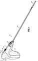
- an exemplary endoscopic surgical device in the form of an endoscope surgical tack applier or tacker, is shown generally as 100.
- the surgical tack applier 100 includes a handle assembly 110 and an endoscopic or anchor retaining/advancing assembly 150 extending from the handle assembly 110 along a longitudinal axis "X".
- An end effector 200 is selectively detachable/attachable from/to the endoscopic assembly 150.
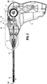
- the handle assembly 110 includes a handle housing 112 formed from a first half-section 112a and a second half section 112b joined to one another.
- the handle assembly 110 includes a trigger 114 pivotably connected to the handle housing 112 and a biasing member 116 disposed within the handle housing 112 that is configured to maintain the trigger 114 in an extended or un-actuated position and to have a spring constant sufficient to return the trigger 114 to the un-actuated position after a driving or firing stroke.
- the trigger 114 defines a gear rack 114a formed thereon that is configured for operative engagement with a pinion gear 118 rotatably supported in the handle housing 112.
- the handle assembly 110 further includes a first bevel gear 120 disposed within the handle housing 112 that is operatively engaged/associated with the pinion gear 118 and a second or pinion-bevel gear 122 operatively engaged or meshed with the first bevel gear 120.
- the pinion-bevel gear 122 is secured to a proximal end of an inner shaft assembly 158 of the endoscopic assembly 150.
- the gear rack 114a thereof causes the pinion gear 118 to rotate in a first direction.
- Rotation of the pinion gear 118 in the first direction results in rotation of the first bevel gear 120 in a first direction and, in turn, rotation of the pinion-bevel gear 122 in a first direction.
- the pinion-bevel gear 122 transmits the rotation to the inner shaft assembly 158 of the endoscopic assembly 150.
- the handle assembly 110 is further provided with a timing system 123 that prevents the trigger 114 from returning to the un-actuated position if the trigger 114 is released after a partial squeeze, and a ratchet mechanism 124 that inhibits or prevents the inner shaft assembly 158 from backing-out or reversing after an anchor or fastener 240 (see e.g., FIG. 2 ) of the end effector 200 has been at least partially driven into tissue.
- a timing system 123 that prevents the trigger 114 from returning to the un-actuated position if the trigger 114 is released after a partial squeeze
- a ratchet mechanism 124 that inhibits or prevents the inner shaft assembly 158 from backing-out or reversing after an anchor or fastener 240 (see e.g., FIG. 2 ) of the end effector 200 has been at least partially driven into tissue.
- the handle assembly 110 includes an articulation knob 126 rotatably supported on the handle housing 112.
- the articulation knob 126 defines an inner helical thread 126a that meshingly receives or engages an outer thread 128a of a connection nut 128 that is non-rotatably connected to a proximal tube portion 156a of an inner articulation tube assembly 156 of the endoscopic assembly 150. Rotation of the articulation knob 126 in first or second directions results in articulating or straightening of the endoscopic assembly 150.
- the handle assembly 110 includes a button 130 supported on the handle housing 112.
- the button 130 is configured to permit and inhibit actuation of the trigger 114, and to effectuate a loading/retention and a release/removal of an end effector 200 to the endoscopic assembly 150.
- the button 130 includes a pin 132 slidably supported in the handle housing 112 and oriented in a direction orthogonal to the longitudinal axis "X" of the endoscopic assembly 150.
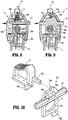
- the pin 132 has a length such that when the button 130 is in a first position, as shown in FIGS.
- a first end of the pin 132 extends from a first side of handle housing 112, and when the button 130 is in a second position, as shown in FIGS. 8 and 9 , a second end of the pin 132 extends from a second side of handle housing 112.
- the button 130 includes a plate 134 supported on and connected to the pin 132.
- the plate 134 defines an elongate slot 134a therein, through which a stem 122a of the pinion-bevel gear 122 extends.
- the elongate slot 134a of plate 134 defines a major axis which is parallel relative to the longitudinal axis of the pin 132. In use, as the pin 132 is moved between the first position and the second position, the plate 134 is moved between respective first and second positions.
- the button 130 further includes a first detent or recess 136a defined in the plate 134 that is engaged by a biasing member 138 (e.g., a plunger spring or torsion spring) when the button 130 is in the first position, and a second detent or recess 136b defined in the plate 134 that is engaged by the biasing member 138 when the button 130 is in the second position.
- a biasing member 138 e.g., a plunger spring or torsion spring
- the engagement of the biasing member 138 in either the first detent 136a or the second detent 136b of the button 130 functions to help maintain the button 130 in either the first or second position.
- the button 130 also includes a first wall 130a extending from the plate 134, and a second wall 130b extending from the plate 134. In use, when the button 130 is in the first position, the first wall 130a thereof blocks or inhibits movement of a load/release slider 140, and when the button 130 is in the second position, the first wall 130a thereof permits movement of load/release slider 140.
- the second wall 130b when the button 130 is in the second position (only achievable when the trigger 114 is in a fully un-actuated or home position), the second wall 130b thereof blocks or inhibits actuation of the trigger 114 by the second wall 130b extending into a notch 114b of the trigger 114; and when the button 130 is in the first position, the second wall 130b is clear of the notch 114b of the trigger 114 to permit actuation of the trigger 114.
- the handle assembly 110 includes a load/release slider 140 (also referred to herein as a slider) slidably supported on the handle housing 112.
- the slider 140 is configured to effectuate a loading/retention and a release/removal of an end effector 200 (see e.g., FIG. 1 ), in the form of a single use loading unit (SULU) or disposable loading unit (DLU), as will be discussed in greater detail below.
- the slider 140 includes a first stem 140a extending proximally therefrom and towards button 130.
- the first stem 140a of the slider 140 is in axial registration with the first wall 130a extending from the plate 134 of the button 130 when the button 130 is in the first position (see e.g., FIG. 7 ), and out of axial registration with the first wall 130a of the button 130 when the button 130 is in the second position (see e.g., FIG. 9 ).
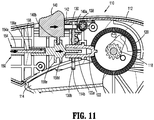
- the slider 140 further includes a second stem 140b extending therefrom in a direction toward the inner shaft assembly 158 of the endoscopic assembly 150. As shown in FIG.11 , the inner shaft assembly 158 supports a pair of axially spaced apart proximal and distal radial flanges 158d, 158e which bookend the second stem 140b of the slider 140.
- the slider 140 In use, when the button 130 is in the second position (wherein trigger 114 is locked in the fully un-actuated position) such that the first stem 140a of the slider 140 is out of axial registration with the first wall 130a of the button 130, the slider 140 is free to move between a first or distal position and a second or proximal position. As the slider 140 is moved from the first position to the second position thereof, the second stem 140b of the slider 140 exerts a force on the proximal radial flange 158d of the inner shaft assembly 158 to urge the inner shaft assembly 158 proximally from a respective first position to a respective second position.
- the second stem 140b of the slider 140 exerts a force on the distal radial flange 158e of the inner shaft assembly 158 to urge the inner shaft assembly 158 distally from the respective second position to the respective first position.
- the slider 140 may be biased in the first or distal portion by a biasing member 142.
- the endoscopic assembly 150 includes an outer tube 152, an outer support tube assembly 154 disposed within outer tube 152, an inner articulation tube assembly 156, and an inner shaft assembly 158.
- the outer support tube assembly 154 includes a proximal support tube portion 154a secured to and extending from the handle housing 112, and a distal support tube portion 154b pivotally connected to the proximal support tube portion 154a by a pivot pin 154c at an articulation joint 160.
- the distal support tube portion 154b supports ball detents 162 in an outer surface thereof.
- the ball detents 162 function to selectively secure and retain an end effector 200 to the endoscopic assembly 150.
- the ball detents 162 are acted on by an outer camming surface/relief 158ci of a coupling member 158c of the inner shaft assembly 158 to move the ball detents 162 radially outward when the inner shaft assembly 158 is in a distal position.
- the inner articulation tube assembly 156 includes a proximal tube portion 156a concentrically and slidably disposed within the proximal tube portion 154a of the outer support tube assembly 154. A proximal end of the proximal tube portion 156a is non-rotatably connected to the connection nut 128.
- the inner articulation tube assembly 156 further includes an articulation link 156b having a proximal end pivotally connected to a distal end of the proximal tube portion 154a, and a distal end pivotally connected to the distal tube portion 154b of the outer support tube assembly 154.
- the proximal tube portion 156a Upon axial translation of the proximal tube portion 156a, for example, in a proximal direction due to rotation of the articulation knob 126 or a distal direction due to a distal movement of the slider 140, the proximal tube portion 156a acts (e.g., pulls or pushes) on the articulation link 156b to cause the articulation link 156b to translate in a respective proximal or distal direction which, in turn, acts on the distal tube portion 154b to cause the distal tube portion 154b to pivot about a pivot axis of the pivot pin 154c which, in turn, causes the end effector 200 to be moved to an articulated or non-articulated orientation relative to the longitudinal axis "X" of the endoscopic assembly 150.
- the proximal tube portion 156a acts (e.g., pulls or pushes) on the articulation link 156b to cause the articulation link 156b to translate in
- the inner shaft assembly 158 includes a proximal rigid shaft portion 158a, a distal flexible shaft portion 158b non-rotatably connected to and extending from a distal end of the proximal rigid shaft portion 158a, and a coupling member 158c non-rotatably connected to a distal end of the distal flexible shaft portion 158b.
- the pinion-bevel gear 122 is non-rotatably connected to a proximal end of the proximal rigid shaft portion 158a of the inner shaft assembly 158.
- the inner shaft assembly 158 is configured such that the distal flexible shaft portion 158b extends across and beyond the articulation joint 160.
- the coupling member 158c is rotatably and slidably supported in the distal support tube portion 154b of the outer support tube assembly 154 so as to accommodate and/or account for variations in length of the distal flexible shaft portion 158b when the distal flexible shaft portion 158b is in a flexed condition.
- the coupling member 158c is substantially tongue shaped and extends in a distal direction distally from the distal support tube portion 154b of the outer support tube assembly 154.
- the coupling member 158c is configured for non-rotatable connection to an inner tube 230 of the end effector 200, as will be discussed in greater detail below.
- the inner actuation shaft assembly 158 is configured to perform at least a pair of functions, a first function relating to the securing and release of an end effector 200 to the distal support tube portion 154b of the outer support tube assembly 154 upon an axial translation thereof, and a second function relating to the firing of the anchors 240 from the end effector 200 when the end effector 200 is coupled to the distal tube portion 154b of the outer support tube assembly 154 upon a rotation thereof.
- end effector 200 in the form of a SULU or DLU, is shown and will be described herein.
- the end effector 200 is selectively connectable to the distal tube portion 154b of the outer support tube assembly 154 of the endoscopic assembly 150.
- the end effector 200 includes an outer tube 210 defining a lumen 210a therethrough, and is configured and dimensioned (e.g., substantially rectangular or dog bone shaped) to receive the distal support tube portion 154b and the coupling member 158c of the endoscopic assembly 150 therein.
- the outer tube 210 defines a proximal key slot 210b for engagement with a key 154d formed in the distal tube portion 154b of the outer support tube assembly 154. In use, when the end effector 200 is connected to the distal tube portion 154b of the outer support tube assembly 154, the key slot 210b and the key 154d engage with one another to properly align the end effector 200 and the endoscopic assembly 150 to one another.
- the end effector 200 further includes a spiral or coil 220 fixedly disposed within a distal portion of the outer tube 210.
- a pair of axially spaced apart retention rings 222a, 222b is also fixedly disposed within the outer tube 210 at a location proximal of the coil 220.
- the end effector 200 also includes an inner tube 230 rotatably disposed within the coil 220.
- the inner tube 230 defines a lumen therethrough, and includes a proximal end portion 230a and a splined distal end portion 230b.
- the proximal end portion 230a of the inner tube 230 is configured and dimensioned to slidably receive the coupling member 158c of the endoscopic assembly 150 therein.
- the inner tube 230 includes a plurality of retention tabs 230c projecting radially outward therefrom and which snap beyond one of the pair of retention rings 222a, 222b, when the inner tube 230 is assembled with the outer tube 210. In this manner, the outer tube 210 and the inner tube 230 are axially fixed and yet rotatable relative to one another.
- the distal end portion 230b of the inner tube 230 is slotted, defining a pair of tines 230b 1 and a pair of channels 230b 2 .
- the distal end portion 230b of the inner tube 230 is capable of accepting a plurality of anchors 240 within the inner tube 230.
- the anchors 240 are loaded into the end effector 200 such that a pair of opposing threaded sections 242a, 242b of the anchors 240 extend through respective channels 230b 2 of the distal end portion 230b of the inner tube 230 and are slidably disposed within the groove of the coil 220, and the pair of tines 230b 1 of the distal end portion 230b of the inner tube 230 are disposed within a pair of slotted sections 244a, 244b of the anchors 240.
- Each of the anchors 240 is loaded into the end effector 200 such that adjacent anchors 240 are not in contact with one another so as to not damage distal tips 246 of the anchors 240.
- the pair of tines 230b 1 of the inner tube 230 transmits the rotation to the anchors 240 and advances the anchors 240 distally owing to head threads 248a, 248b of the anchors 240 engaging with the coil 220.
- a single complete and full actuation of the trigger 114 results in a firing of a single anchor 240 from the end effector 200.
- the surgical tacker 200 may be repeatedly fired to fire anchors 240 from the end effector 200 until the surgical procedure is complete or until the end effector 200 is spent of anchors 240. If the end effector 200 is spent of anchors 240, and if additional anchors 240 are required to complete the surgical procedure, the spent end effector 200 may be replaced with a new (e.g., loaded with anchors 240) end effector 200.
- the button 130 of the handle assembly 110 is moved from the first position to the second position, as described above, such that the trigger 114 is prevented from actuation and the slider 140 is free to move.
- the slider 140 is moved from the first position to the second position, as also described above.
- the second stem 140b of the slider 140 exerts a force on the proximal radial flange 158d of the inner shaft assembly 158 to urge the inner shaft assembly 158, and in turn the coupling member 158c thereof, proximally from a respective first position to a respective second position.
- the ball detents 162 are free to drop or move radially inward of the outer tube 152 as the outer camming surface/relief 158c 1 of the coupling member 158c is moved into axial registration with the ball detents 162. With the ball detents 162 free to drop or move radially inward, the end effector 200 may be fully coupled to the distal support tube portion 154b of the endoscopic assembly 150.
- the end effector 200 may only be removed and replaced when trigger 114 is in the fully un-actuated, home and locked position. As such, the end effector 200 cannot be removed or replaced or loaded while the trigger 114 is in a short-stroked condition (e.g., partially actuated).
- the slider 140 With a new end effector 200 fully coupled to distal support tube portion 154b of the endoscopic assembly 150, the slider 140 is moved from the second position to the first position to secure or lock the end effector 200 to the distal support tube portion 154b of the endoscopic assembly 150.
- the second stem 140b of the slider 140 exerts a force on the distal radial flange 158e of the inner shaft assembly 158 to urge the inner shaft assembly 158, and in turn the coupling member 158c thereof, distally from the second position to the first position.
- the ball detents 162 are urged by outer the camming surface/relief 158c 1 of the coupling member 158 to move the ball detents 162 radially outward.
- the ball detents 162 move radially outward a portion of each of the ball detents 162 enters a respective aperture 210c defined in the outer tube 210 of the end effector 200 to secure the end effector 200 to the distal support tube portion 154b of the endoscopic assembly 150.
- the button 130 is moved from the second position to the first position, as described above, such that slider 140 is prevented from actuation and such that trigger 114 is free to move.
- a user actuates or slides the slider 140 to release the spent end effector 200, decouples the end effector 200 from the endoscopic assembly 150, loads or connects a new end effector 200 to the endoscopic assembly 150 by fitting the proximal end portion 230a of the inner tube 230 over the coupling member 158c of the endoscopic assembly 150, and releases the slider 140 to retain the new end effector 200 on the endoscopic assembly 150. Since the trigger 114 is in the fully un-actuated position with the loading of a new end effector 200, the timing system 123 is reset such that each full actuation of the trigger 114 results in the firing of a single anchor 240.
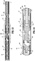
- a shipping wedge 300 in accordance with an embodiment of the present disclosure, is shown disposed over an end effector 200.
- the shipping wedge 300 is configured and dimensioned to releasably connect to the end effector 200, to inhibit premature rotation of the inner tube 230 of the end effector 200, and to facilitate proper loading of the end effector 200 to the endoscopic assembly 150 of the surgical tack applier 100.
- the shipping wedge 300 includes an elongate body 310 extending along a longitudinal axis "A".
- the elongate body 310 is tubular in shape and defines a lumen or channel 311 extending longitudinally therethrough.
- the channel 311 of the elongate body 310 has a diameter sufficient to releasably accommodate the end effector 200 therein and along.
- the elongate body 310 includes a proximal portion 310a defining a circumferential wall 312 configured to extend completely around a proximal end 200a of the end effector 200 and be axially aligned therewith.
- the elongate body 310 includes a distal portion 310b that may extend longitudinally beyond a distal end 200b of the end effector 200.
- a handle or wing 320 is integrally formed with or secured to the elongate body 310.
- the wing 320 extends transversely from the elongate body 310 along a first transverse axis "B" that is orthogonal to the longitudinal axis "A" of the elongate body 310.
- the handle 320 may be utilized (e.g., gripped) by a user to load the end effector 200 onto the endoscopic assembly 150 and/or to remove the shipping wedge 300 from the end effector 200 once the end effector 200 is properly loaded onto the endoscopic assembly 150.
- a pair of guard walls or rails 322a, 322b are also integrally formed with or secured to the elongated body 310.
- the pair of guard walls 322a, 322b extend transversely from the elongate body 310 along a second transverse axis "C" that is orthogonal to the first transverse axis "B" of the handle 320 as well as the longitudinal axis "B” of the elongate body 310.
- the pair of guard walls 322a, 322b is disposed in substantially parallel and spaced relation relative to each other, on opposed sides of an arm 330 disposed therebetween.
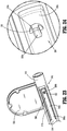
- the arm 330 has a cantilever configuration including a first or distal end 330a coupled to a side wall 314 of the elongate body 310 and a second or proximal end 330b that is free to move laterally with respect to the side wall 314.
- the arm 330 is biased to extend within a slot 313 defined in the side wall 314.
- the arm 330 may be integrally formed with the side wall 314 of the elongate body 310 by cutting the slot 313 in a generally U-shape or, alternatively, the arm 330 may be secured to the side wall 314 of the elongate body 310 and positioned within the slot 313 having, for example, a rectangular shape. It is envisioned that the geometry of the slot 313 may vary and be configured to accommodate the arm 330 therein.
- a projection 332 extends from an inner surface 330c of the arm 330 adjacent the proximal end 330b of the arm 330.
- the projection 332 includes a first surface 332a and a cam ramp 332b. As shown in FIGS. 24 and 25 , the projection 332 extends into the channel 311 of the elongate body 310 along an axis that is aligned with or parallel to the second transverse axis "Z" of the pair of guard walls 322a, 322b.
- the first surface 332a of the projection 332 extends laterally into the channel 311 and the cam ramp 332b tapers from the first surface 332a of the projection 332 distally towards the inner surface 330c of the arm 330.
- the projection 332 is configured and dimensioned for insertion into an aperture 210d (see also, FIG. 18 ) defined in the outer tube 210 of the end effector 200.
- the projection 332 When the shipping wedge 300 is attached to the end effector 200, the projection 332 extends in close proximity to or in contact with the proximal end portion 230a (see e.g., FIG. 19 ) of the inner tube 230 of the end effector 200. By extending this amount, the projection 332 inhibits rotation of the inner tube 230 relative to the outer tube 210 by blocking or contacting the proximal end portion 230a of the inner tube 230 if the inner tube 230 experiences any rotation relative to the outer tube 210.
- the first surface 332a of the projection 332 further ensures simultaneous advancement of the end effector 200 with the shipping wedge 300 by inhibiting advancement of the shipping wedge 300 relative to the end effector 200 during assembly of the end effector 200 onto the endoscopic assembly 150 of the surgical tack applier 100.
- the cam ramp 332b of the projection 332 enables the arm 330 to be deflected laterally outward and away from the end effector 200 upon proper loading of the end effector 200 to the endoscopic assembly 150 for removal of the shipping wedge 300 from the end effector 200, as described in further detail below.
- the end effector 200 is loaded onto the endoscopic assembly 150 of the surgical tack applier 100 (see e.g., FIG. 1 ) by first preparing the surgical tack applier 100 for receipt of the end effector 200 by moving the slider 140 from the first position to the second position, as described above, to urge the inner shaft assembly 158, and thus the coupling member 158c, proximally from the first position to the second position as shown, for example, in FIGS. 15 and 16 .
- the ball detents 162 drop or move radially inward of the outer tube 152 as the outer camming surface/relief 158c 1 of the coupling member 158c is moved into axial registration with the ball detents 162 so that the end effector 200 may be fully coupled to the distal support tube portion 154b of the endoscopic assembly 150.
- the end effector 200 with attached shipping wedge 300 is then advanced over the endoscopic assembly 150 such that the distal support tube portion 154b of the endoscopic assembly 150 is received within the outer tube 210 of the end effector 200 with the key 154d ( FIG. 18 ) of the outer support tube assembly 154 positioned within the proximal key slot 210b of the outer tube 210 of the end effector 200.
- the slider 140 is moved from the second position to the first position, as described above, to secure or lock the end effector 200 to the distal support tube portion 154b of the endoscopic assembly 150.
- the inner shaft assembly 158 and in turn the coupling member 158c thereof, is moved distally from the second position to the first position.
- the coupling member 158c is moved from the second position to the first position, the ball detents 162 are urged by the outer camming surface/relief 158c 1 of the coupling member 158 to move the ball detents 162 radially outward as shown, for example, in FIGS. 13 and 14 .
- each of the ball detents 162 moves radially outward a portion of each of the ball detents 162 enters the respective aperture 210c defined in the outer tube 210 of the end effector 200 to secure the end effector 200 to the distal support tube portion 154b of the endoscopic assembly 150.
- the shipping wedge 300 fully encompasses the end effector 200 to prevent a user from forcing the end effector 200 onto the surgical tack applier 100 during installation thereof.
- the circumferential wall 312 of the elongate body 310 of the shipping wedge 300 prevents or minimizes deformation of the outer tube 210 of the end effector 200 during the installation onto the endoscopic assembly 150 (e.g., by preventing a user's ability to force the end effector 200 onto the endoscopic assembly 150 which may result in premature separate of the end effector 200 from the surgical tack applier 100).
- the arm 330 of the shipping wedge 300 will flex or be deflected away from the end effector 200 via the cam ramp 332b of the protrusion 332 so that the shipping wedge 300 can be removed from the end effector 200 by sliding the shipping wedge 300 linearly along and away from the end effector 200.
- the shipping wedge 300 ensures proper loading of the end effector 200 onto the endoscopic assembly 150 of the surgical tack applier 100 as the shipping wedge 300 will only separate from the end effector 200 when properly loaded onto the endoscopic assembly 150.
- the shipping wedge 300 will not separate from the end effector 200 until a force is reach that is less than a force it takes to remove a properly loaded end effector 200 from the endoscopic assembly 150 but greater than a force it takes to remove the end effector 200 from the endoscopic assembly 150 when the ball detents 162 are not fully/properly engaged.
- This configuration eliminates a false position that the end effector 200 is properly engaged with the endoscopic assembly 150 by, for example, preventing a user from forcing the end effector 200 onto the endoscopic assembly 150 improperly and/or preventing the shipping wedge 300 from being removed from the end effector 200 if the ball detents 162 are not properly and fully engaged with the end effector 200.
- the shipping wedge 400 is configured and dimensioned to releasably connect to an end effector 200, as shown in FIG. 27 , and to facilitate loading of the end effector 200 to the endoscopic assembly 150 of the surgical tack applier 100 while inhibiting premature actuation of the end effector 200.
- the shipping wedge 400 includes an elongate body 410 extending along a longitudinal axis "Y".
- the elongate body 410 includes a proximal portion 410a and a distal portion 410b, and defines a channel 411 extending longitudinally therethrough that is configured and dimensioned to receive and releasably retain the end effector 200 therein.
- a distal portion 411b of the channel 411 defined in the distal portion 410b of the elongate body 410 is substantially tubular in shape and extends completely around a distal portion 200b of the end effector 200 to securely retain the end effector 200 therein.
- the distal portion 410b of the elongate body 410 may include side cut outs 412 to facilitate the formation of the channel 411 therein, or the distal portion 410b of the elongate body 410 may be solid with the channel 411 formed by molding the elongate body 410 about a core pin.
- the distal portion 410b of the elongate body 410 may extend longitudinally beyond the distal portion 200b of the end effector 200 and have a closed end 410c.
- the proximal portion 410a of the elongate body 410 includes first and second arms 414, 416 that extend proximally from the distal portion 410b.
- the first arm 414 is biased to extend along an axis that is disposed at an angle with respect to the longitudinal axis "Y"
- the second arm 416 is biased to extend along an axis that is substantially parallel to the longitudinal axis "Y”.
- the first arm 414 includes a pair of fingers 414a, 414b extending towards the second arm 416.
- the pair of fingers 414a, 414b are disposed in parallel and spaced relation relative to each other and define a slot 414c therebetween that is coincident with the channel 411 of the elongate body 410 and dimensioned to receive the end effector 200 therein.
- the second arm 416 includes a locking tab 418 secured thereto that extends towards the first arm 414 and into the slot 414c defined between the pair of fingers 414a, 414b.
- the locking tab 418 extends along a transverse axis "Z" that is orthogonal to the longitudinal axis "Y”.
- the locking tab 418 is formed from a rigid material to prevent or minimize deflection away from the transverse axis "Z".
- the locking tab 418 is configured for positioning within the end effector 200 as shown in FIGS. 27 and 28 .
- the locking tab 418 extends through the aperture 210d defined in the outer tube 210 of the end effector 200 and extends in close proximity to or in contact with the proximal end portion 230a of the inner tube 230 of the end effector 200. By extending this amount, the locking tab 418 inhibits rotation of the inner tube 230 relative to the outer tube 210 by blocking or contacting the proximal end portion 230a of the inner tube 230 if the inner tube 230 experiences any rotation relative to the outer tube 210.
- the first and second arms 414, 416 are flexible so that the first arm 414 may be pressed towards the second arm 416, as shown in FIG. 29 .
- the first arm 414 Upon pressing the first arm 414 toward the second arm 416, the first arm 414 is displaced and moves to a deflected position such that the first arm 414 extends along an axis substantially parallel to the longitudinal axis "Y" of the elongate body 410.
- the pair of fingers 414a, 414b of the first arm 414 contacts and acts on the second arm 416 by pushing the second arm 416 away from the end effector 200 such that the second arm 416 is displaced and moved to a deflected position that extends along an axis disposed at an angle with respect to the longitudinal axis "Y" of the elongate body 410. Movement of the second arm 416 to the deflected position causes the locking tab 418 to disengage from the end effector 200.
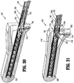
- the end effector 200 As shown in FIGS. 27 and 28 , the end effector 200, with the shipping wedge 400 installed thereon, is loaded onto the endoscopic assembly 150 of the surgical tack applier 100 without requiring the slider 140 (see e.g., FIG. 11 ) of the surgical tack applier 100 to be actuated (e.g., moved from the first position to the second position).
- the end effector 200, with the attached shipping wedge 400 is advanced over the endoscopic assembly 150 such that the distal tube portion 154b of the endoscopic assembly 150 is received within the outer tube 210 of the end effector 200. As shown in FIG.
- the locking tab 418 of the shipping wedge 400 contacts the coupling member 158c of the inner shaft assembly 158 of the endoscopic assembly 150 and moves the coupling member 158c and thus, the inner shaft assembly 158 proximally from the first position to the second position.
- the coupling member 158c is moved from the first position to the second position, the ball detents 162 drop or move radially inward of the outer tube 152 thereby allowing the end effector 200 to be installed thereon.
- the slider 140 is also moved from the first position to the second position.
- the first arm 414 is pressed towards the end effector 200 which, in turn, moves the second arm 416 away from the end effector 200 as shown in FIG. 31 . Movement of the second arm 416 away from the end effector 200 causes the locking tab 418 to disengage from the end effector 200. With the force of the locking tab 418 removed, the inner shaft assembly 158 and thus, the coupling member 158c, of the endoscopic assembly 150 moves distally from the second position to the first position.
- the ball detents 162 are urged by the outer camming surface/relief 158c 1 of the coupling member 158c to move the ball detents 162 radially outward such that a portion of each of the ball detents 162 enters the respective aperture 210c defined in the outer tube 210 of the end effector 200 to secure the end effector 200 to the distal support tube portion 154b of the endoscopic assembly 150.
- the slider 140 which may be biased in the first position as described above, is also moved back to the first position.
- the shipping wedge 400 is removed from the end effector 200 by sliding the shipping wedge 400 linearly along and distally away from the end effector 200.
- the shipping wedge 400 allows for the installation load to be distributed around the hand of the user and to the distal end 200b of the end effector 200.
- the locking tab 418 prevents the inner shaft assembly 158 from connecting to the end effector 200 until displaced thereby preventing the inner tube 230 of the end effector 200 from spinning as well as the inner shaft assembly 158 of the endoscopic assembly 150 from spinning until the trigger 114 is pulled. Additionally, the locking tab 418 displaces the inner shaft assembly 158 linearly to release the ball detents 162 thereby allowing the end effector 200 to be installed onto the endoscopic assembly 150 without having to move the slider 140 manually. Accordingly, the slider 140 is actuated by a user only to remove an end effector 200 from the endoscopic assembly 150, as described above. As the slider 140 travels in an opposite direction as the removal of the end effector 200, it is more ergonomic to use the slider 140 for removal of the end effector 200 than for installation.
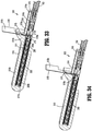
- FIG. 32 a shipping wedge 500 in accordance with another embodiment of the present disclosure, is shown releasably disposed over an end effector 200.
- the shipping wedge 500 is substantially similar to the shipping wedge 400 and will be described with respect to the differences therebetween.
- the shipping wedge 500 includes an elongated body 510 extending along a longitudinal axis "Y".
- the elongate body 510 includes a proximal portion 510a and a distal portion 510b, and defines a channel 511 extending longitudinally therethrough that is configured and dimensioned to receive and releasably retain the end effector 200 therein.
- the distal portion 510b of the elongate body 510 defines a distal portion 511b of the channel 511 that is substantially tubular in shape and extends completely around the distal portion 200b of the end effector 200.
- the proximal portion 510a of the elongate body 510 includes at least one arm 514 extending proximally from the distal portion 510b along an axis substantially parallel to the longitudinal axis "Y" of the elongate body 510.
- the arm 514 includes a proximal portion 514a including a protuberance or latch 516 extending from an inner surface 514c of the arm 514.
- the latch 516 includes a first surface 516a and a cam ramp 516b.
- the latch 516 extends into the channel 511 of the elongate body 510 with the first surface 516a extending laterally into the channel 511 and the cam ramp 516b tapering from the first surface 516a proximally towards the inner surface 514c of the arm 514.
- the latch 516 is configured and dimensioned to releasably engage a proximal end of the distal tube portion 154b of the endoscopic assembly 150.
- the arm 514 includes a distal portion 514b including a slit 515 defined therethrough.
- a locking tab 518 is slidably disposed within the slit 515.
- the locking tab 518 includes a first end 518a positionable within the channel 511 of the elongate body 510 and a second end 518b positioned radially outward of the arm 514.
- the second end 518b defines a pull tab that is engageable by a user to move the locking tab 518 from a first position in which the first end 518a of the locking tab 518 is positioned within the channel 511 of the elongate body 510, as shown in FIG. 33 , and a second position in which the first end 518a of the locking tab 518 is moved into the slit 515 defined in the arm 514, as shown in FIG. 34 .
- the locking tab 518 is configured for positioning within the end effector 200 as shown in FIGS. 32 and 33 .
- the locking tab 518 extends through the aperture 210d defined in the outer tube 210 of the end effector 200 and extends in close proximity to or in contact with the proximal end portion 230a of the inner tube 230 of the end effector 200.
- the end effector 200, with the shipping wedge 500 installed thereon, is loaded onto the endoscopic assembly 150 in a similar manner as discussed above with regard to the shipping wedge 400, except that the end effector 200 is advanced over the endoscopic assembly 150 until the latch 516 of the arm 514 of the shipping wedge 500 engages the endoscopic assembly 150.
- the second end 518b of the locking tab 518 is pulled by a user to remove the first end 518a of the locking tab 518 from within the end effector 200, as shown in FIG. 34 , to secure the end effector 200 to the endoscopic assembly 150, as described above with regard to the shipping wedge 400.
- Pulling on the locking tab 518 causes the arm 514 of the shipping wedge 500 to flex or be deflected laterally away from the end effector 200 which releases the latch 516 so that the shipping wedge 500 can be removed from the end effector 200 by sliding the shipping wedge 500 linearly along and distally away from the end effector 200.
Landscapes
- Health & Medical Sciences (AREA)
- Life Sciences & Earth Sciences (AREA)
- Surgery (AREA)
- Heart & Thoracic Surgery (AREA)
- Engineering & Computer Science (AREA)
- Biomedical Technology (AREA)
- Nuclear Medicine, Radiotherapy & Molecular Imaging (AREA)
- Medical Informatics (AREA)
- Molecular Biology (AREA)
- Animal Behavior & Ethology (AREA)
- General Health & Medical Sciences (AREA)
- Public Health (AREA)
- Veterinary Medicine (AREA)
- Surgical Instruments (AREA)
Applications Claiming Priority (2)
| Application Number | Priority Date | Filing Date | Title |
|---|---|---|---|
| US201862665548P | 2018-05-02 | 2018-05-02 | |
| US16/279,180 US11298126B2 (en) | 2018-05-02 | 2019-02-19 | Shipping wedge for end effector installation onto surgical devices |
Publications (2)
| Publication Number | Publication Date |
|---|---|
| EP3572009A2 true EP3572009A2 (de) | 2019-11-27 |
| EP3572009A3 EP3572009A3 (de) | 2020-01-22 |
Family
ID=66349459
Family Applications (1)
| Application Number | Title | Priority Date | Filing Date |
|---|---|---|---|
| EP19172130.7A Withdrawn EP3572009A3 (de) | 2018-05-02 | 2019-05-01 | Versandkeile zur installation eines endeffektors auf chirurgischen vorrichtungen |
Country Status (2)
| Country | Link |
|---|---|
| US (2) | US11298126B2 (de) |
| EP (1) | EP3572009A3 (de) |
Cited By (1)
| Publication number | Priority date | Publication date | Assignee | Title |
|---|---|---|---|---|
| EP3943016A1 (de) * | 2020-07-21 | 2022-01-26 | Covidien LP | Kartuschenausrichtungsmechanismus für chirurgische vorrichtungen |
Families Citing this family (5)
| Publication number | Priority date | Publication date | Assignee | Title |
|---|---|---|---|---|
| US11298126B2 (en) | 2018-05-02 | 2022-04-12 | Covidien Lp | Shipping wedge for end effector installation onto surgical devices |
| US11690693B2 (en) * | 2018-07-12 | 2023-07-04 | Davol Inc. | Surgical instrument with fastener preload lockout |
| WO2020214657A1 (en) * | 2019-04-17 | 2020-10-22 | Davol Inc. | Surgical instrument with fastener preload lock-out |
| US11331098B2 (en) * | 2020-04-01 | 2022-05-17 | Covidien Lp | Sled detection device |
| US11426159B2 (en) * | 2020-04-01 | 2022-08-30 | Covidien Lp | Sled detection device |
Citations (2)
| Publication number | Priority date | Publication date | Assignee | Title |
|---|---|---|---|---|
| US20160166255A1 (en) | 2013-06-28 | 2016-06-16 | Covidien Lp | Surgical instrument including rotating end effector and rotation-limiting structure |
| US20160270835A1 (en) | 2015-03-17 | 2016-09-22 | Covidien Lp | Connecting end effectors to surgical devices |
Family Cites Families (220)
| Publication number | Priority date | Publication date | Assignee | Title |
|---|---|---|---|---|
| US3866510A (en) | 1967-06-05 | 1975-02-18 | Carl B H Eibes | Self-tapping threaded bushings |
| DE1816949B1 (de) | 1968-12-24 | 1970-05-27 | Piv Antrieb Reimers Kg Werner | Kegelscheiben-Umschlingungsgetriebe |
| DE2910546C3 (de) | 1979-03-17 | 1982-05-27 | P.I.V. Antrieb Werner Reimers GmbH & Co KG, 6380 Bad Homburg | Kegelscheiben-Umschlingungsgetriebe |
| US4884572A (en) | 1986-05-20 | 1989-12-05 | Concept, Inc. | Tack and applicator for treating torn bodily material in vivo |
| US4730726A (en) | 1987-04-21 | 1988-03-15 | United States Surgical Corporation | Sealed sterile package |
| CH681273A5 (de) | 1988-12-16 | 1993-02-26 | Sulzer Ag | |
| US5382254A (en) | 1989-07-18 | 1995-01-17 | United States Surgical Corporation | Actuating handle for surgical instruments |
| US5129906A (en) | 1989-09-08 | 1992-07-14 | Linvatec Corporation | Bioabsorbable tack for joining bodily tissue and in vivo method and apparatus for deploying same |
| US5236563A (en) | 1990-06-18 | 1993-08-17 | Advanced Surface Technology Inc. | Surface-modified bioabsorbables |
| US5085661A (en) | 1990-10-29 | 1992-02-04 | Gerald Moss | Surgical fastener implantation device |
| DE4108952A1 (de) | 1991-03-19 | 1992-09-24 | Beiersdorf Ag | Geraet zum setzen von wundklammern |
| US5144942A (en) | 1991-03-21 | 1992-09-08 | United States Surgical Corporation | Endoscopic instrumentation kit and package therefor |
| US5171249A (en) | 1991-04-04 | 1992-12-15 | Ethicon, Inc. | Endoscopic multiple ligating clip applier |
| US5171247A (en) | 1991-04-04 | 1992-12-15 | Ethicon, Inc. | Endoscopic multiple ligating clip applier with rotating shaft |
| US5156267A (en) | 1991-06-14 | 1992-10-20 | Dynamic Bio-Apparatuses, Inc. | Syringe inhibiting container |
| US5207697A (en) | 1991-06-27 | 1993-05-04 | Stryker Corporation | Battery powered surgical handpiece |
| US5228256A (en) | 1991-10-02 | 1993-07-20 | Ross Dreveny | Anchor means and apparatus for installing same |
| US5312023A (en) | 1991-10-18 | 1994-05-17 | United States Surgical Corporation | Self contained gas powered surgical apparatus |
| US5356064A (en) | 1991-10-18 | 1994-10-18 | United States Surgical Corporation | Apparatus and method for applying surgical staples to attach an object to body tissue |
| US5397046A (en) | 1991-10-18 | 1995-03-14 | United States Surgical Corporation | Lockout mechanism for surgical apparatus |
| US5433721A (en) | 1992-01-17 | 1995-07-18 | Ethicon, Inc. | Endoscopic instrument having a torsionally stiff drive shaft for applying fasteners to tissue |
| CA2088883A1 (en) | 1992-02-13 | 1993-08-14 | David T. Green | Endoscopic ligating instrument |
| US5246450A (en) | 1992-03-10 | 1993-09-21 | Edward Weck Incorporated | High capacity medical clip feeding and dispensing mechanism |
| US5342373A (en) | 1992-09-14 | 1994-08-30 | Ethicon, Inc. | Sterile clips and instrument for their placement |
| US5662662A (en) | 1992-10-09 | 1997-09-02 | Ethicon Endo-Surgery, Inc. | Surgical instrument and method |
| US5601224A (en) | 1992-10-09 | 1997-02-11 | Ethicon, Inc. | Surgical instrument |
| US5330487A (en) | 1992-12-17 | 1994-07-19 | Tfi Acquistion Corp. | Drive mechanism for surgical instruments |
| US5403327A (en) | 1992-12-31 | 1995-04-04 | Pilling Weck Incorporated | Surgical clip applier |
| US5398861A (en) | 1993-04-16 | 1995-03-21 | United States Surgical Corporation | Device for driving surgical fasteners |
| US5353929A (en) | 1993-04-19 | 1994-10-11 | United States Surgical Corporation | Package for surgical instrument |
| US5467911A (en) | 1993-04-27 | 1995-11-21 | Olympus Optical Co., Ltd. | Surgical device for stapling and fastening body tissues |
| EP0622048B1 (de) | 1993-04-27 | 1997-05-21 | American Cyanamid Company | Automatischer, laparoskopischer Applikator für Abbindeklammern |
| US5439468A (en) | 1993-05-07 | 1995-08-08 | Ethicon Endo-Surgery | Surgical clip applier |
| US5522844A (en) | 1993-06-22 | 1996-06-04 | Johnson; Lanny L. | Suture anchor, suture anchor installation device and method for attaching a suture to a bone |
| US5792165A (en) | 1993-07-21 | 1998-08-11 | Charles H. Klieman | Endoscopic instrument with detachable end effector |
| WO1995003745A1 (en) | 1993-08-03 | 1995-02-09 | Howmedica Inc. | Ratcheting compression device |
| US5344061A (en) | 1993-08-03 | 1994-09-06 | Lawrence Crainich | Ratchet assembly for medical instrument |
| US5407070A (en) | 1993-08-18 | 1995-04-18 | Bascos; Christine M. | One-time resealable package for needled medical devices |
| US5381896A (en) | 1993-10-06 | 1995-01-17 | Ethicon, Inc. | Presentation tray for surgical instruments |
| US5607436A (en) | 1993-10-08 | 1997-03-04 | United States Surgical Corporation | Apparatus for applying surgical clips |
| AU1011595A (en) | 1994-01-13 | 1995-07-20 | Ethicon Inc. | Spiral surgical tack |
| US5466243A (en) | 1994-02-17 | 1995-11-14 | Arthrex, Inc. | Method and apparatus for installing a suture anchor through a hollow cannulated grasper |
| CA2143560C (en) | 1994-03-02 | 2007-01-16 | Mark Fogelberg | Sterile occlusion fasteners and instrument and method for their placement |
| US5681330A (en) | 1994-03-02 | 1997-10-28 | Ethicon Endo-Surgery, Inc. | Sterile occlusion fasteners and instrument and method for their placement |
| US5474566A (en) | 1994-05-05 | 1995-12-12 | United States Surgical Corporation | Self-contained powered surgical apparatus |
| US5601571A (en) | 1994-05-17 | 1997-02-11 | Moss; Gerald | Surgical fastener implantation device |
| EP0699418A1 (de) | 1994-08-05 | 1996-03-06 | United States Surgical Corporation | Unabhängig motorisch betriebenes chirurgisches Gerät |
| US5582616A (en) | 1994-08-05 | 1996-12-10 | Origin Medsystems, Inc. | Surgical helical fastener with applicator |
| US5562685A (en) | 1994-09-16 | 1996-10-08 | General Surgical Innovations, Inc. | Surgical instrument for placing suture or fasteners |
| US5730744A (en) | 1994-09-27 | 1998-03-24 | Justin; Daniel F. | Soft tissue screw, delivery device, and method |
| US5685474A (en) | 1994-10-04 | 1997-11-11 | United States Surgical Corporation | Tactile indicator for surgical instrument |
| US5704534A (en) | 1994-12-19 | 1998-01-06 | Ethicon Endo-Surgery, Inc. | Articulation assembly for surgical instruments |
| DE19509966A1 (de) | 1995-03-18 | 1996-09-19 | Frank Ullrich Schuetz | Heftgerät und Heftnagel für die Chirurgie |
| US5553765A (en) | 1995-04-28 | 1996-09-10 | Ethicon Endo-Surgery, Inc. | Surgical stapler with improved operating lever mounting arrangement |
| US5626613A (en) | 1995-05-04 | 1997-05-06 | Arthrex, Inc. | Corkscrew suture anchor and driver |
| US5697935A (en) | 1995-09-12 | 1997-12-16 | Medex Marketing, Inc. | Device and method for removing fastening implements from bone |
| US5997552A (en) | 1995-10-20 | 1999-12-07 | United States Surgical Corporation | Meniscal fastener applying device |
| US5582615A (en) | 1995-10-30 | 1996-12-10 | Pilling Weck, Incorporated | Handle for surgical clip applicator systems |
| JPH09149906A (ja) | 1995-11-29 | 1997-06-10 | Nagoya Rashi Seisakusho:Kk | 骨疾患治療用具 |
| US5649931A (en) | 1996-01-16 | 1997-07-22 | Zimmer, Inc. | Orthopaedic apparatus for driving and/or removing a bone screw |
| US5762255A (en) | 1996-02-20 | 1998-06-09 | Richard-Allan Medical Industries, Inc. | Surgical instrument with improvement safety lockout mechanisms |
| US6402780B2 (en) | 1996-02-23 | 2002-06-11 | Cardiovascular Technologies, L.L.C. | Means and method of replacing a heart valve in a minimally invasive manner |
| US6099537A (en) | 1996-02-26 | 2000-08-08 | Olympus Optical Co., Ltd. | Medical treatment instrument |
| US5782844A (en) | 1996-03-05 | 1998-07-21 | Inbae Yoon | Suture spring device applicator |
| US5747953A (en) | 1996-03-29 | 1998-05-05 | Stryker Corporation | Cordless, battery operated surical tool |
| US5732806A (en) | 1996-03-29 | 1998-03-31 | Pilling Weck, Incorporated | Compensator to prevent backlash in a surgical instrument |
| EP0800796A1 (de) | 1996-04-12 | 1997-10-15 | Caron, Philippe | Schaubgerät mit Schraubenmagazin, insbesondere für die Gesichts- und Kieferchirurgie |
| US7611521B2 (en) | 1996-09-13 | 2009-11-03 | Tendon Technology, Ltd. | Apparatus and methods for tendon or ligament repair |
| US5830221A (en) | 1996-09-20 | 1998-11-03 | United States Surgical Corporation | Coil fastener applier |
| WO1998011814A2 (en) | 1996-09-20 | 1998-03-26 | United States Surgical Corporation | Coil fastener applier and remover |
| EP0834280B1 (de) | 1996-10-04 | 2004-01-02 | United States Surgical Corporation | Vorrichtung zum Anbringen eines Gewebe-Befestigungselements |
| US5928252A (en) | 1997-01-21 | 1999-07-27 | Regen Biologics, Inc. | Device and method for driving a needle and meniscal repair |
| US5843087A (en) | 1997-01-30 | 1998-12-01 | Ethicon, Inc. | Suture anchor installation tool |
| US5897564A (en) | 1997-04-08 | 1999-04-27 | Ethicon Endo-Surgery, Inc. | Endoscopic instrument assembly for fastening tissue |
| US5910105A (en) | 1997-04-14 | 1999-06-08 | C.R. Bard, Inc. | Control handle for an endoscope |
| US5941439A (en) | 1997-05-14 | 1999-08-24 | Mitek Surgical Products, Inc. | Applicator and method for deploying a surgical fastener in tissue |
| US5957924A (en) | 1997-05-22 | 1999-09-28 | Bionx Implants Oy | Installation tool for suture anchor |
| US6010513A (en) | 1997-11-26 | 2000-01-04 | Bionx Implants Oy | Device for installing a tissue fastener |
| US6457625B1 (en) | 1998-02-17 | 2002-10-01 | Bionx Implants, Oy | Device for installing a tissue fastener |
| US5961524A (en) | 1998-03-11 | 1999-10-05 | Stryker Technologies Corporation | Screw and method of attachment to a substrate |
| US7491232B2 (en) | 1998-09-18 | 2009-02-17 | Aptus Endosystems, Inc. | Catheter-based fastener implantation apparatus and methods with implantation force resolution |
| US8075570B2 (en) | 2001-11-28 | 2011-12-13 | Aptus Endosystems, Inc. | Intraluminal prosthesis attachment systems and methods |
| US7591842B2 (en) | 1998-03-13 | 2009-09-22 | Aptus Endosystems, Inc. | Endovascular prosthesis with suture holder |
| US5976160A (en) | 1998-03-31 | 1999-11-02 | Design Standards Corporation | Handle mechanism with two distinct pivot points |
| US5931844A (en) | 1998-03-31 | 1999-08-03 | Smith & Nephew, Inc. | Surgical drive tool |
| AU733868B2 (en) | 1998-05-12 | 2001-05-31 | Boston Scientific Limited | Manual bone anchor placement devices |
| US6261302B1 (en) | 1998-06-26 | 2001-07-17 | Ethicon Endo-Surgery, Inc. | Applier for implantable surgical marker |
| US6228098B1 (en) | 1998-07-10 | 2001-05-08 | General Surgical Innovations, Inc. | Apparatus and method for surgical fastening |
| US6039753A (en) | 1998-07-16 | 2000-03-21 | Meislin; Robert | Single unit surgical fastener and method |
| US5911722A (en) | 1998-07-23 | 1999-06-15 | Millenium Devices Llc | Leban/Gordon surgical hand driver |
| US6146387A (en) | 1998-08-26 | 2000-11-14 | Linvatec Corporation | Cannulated tissue anchor system |
| WO2000016701A1 (en) | 1998-09-18 | 2000-03-30 | United States Surgical Corporation | Endovascular fastener applicator |
| US6235058B1 (en) | 1998-10-19 | 2001-05-22 | Douglas B. Huene | Bone plug anchoring device and methods for anchoring one or more tendons or other grafts using the bone plug anchoring device |
| US6887244B1 (en) | 1998-12-16 | 2005-05-03 | Medtronic, Inc. | Cordless surgical handpiece with disposable battery; and method |
| US6126670A (en) | 1998-12-16 | 2000-10-03 | Medtronic, Inc. | Cordless surgical handpiece with disposable battery; and method |
| WO2000040159A1 (en) | 1998-12-31 | 2000-07-13 | Yeung Teresa T | Tissue fastening devices and delivery means |
| US6074395A (en) | 1999-02-02 | 2000-06-13 | Linvatec Corporation | Cannulated tissue anchor insertion system |
| US6387113B1 (en) | 1999-02-02 | 2002-05-14 | Biomet, Inc. | Method and apparatus for repairing a torn meniscus |
| US6402757B1 (en) | 1999-03-12 | 2002-06-11 | Biomet, Inc. | Cannulated fastener system for repair of bone fracture |
| US20050222665A1 (en) | 1999-04-23 | 2005-10-06 | Ernest Aranyi | Endovascular fastener applicator |
| FR2795301B1 (fr) | 1999-06-25 | 2001-08-31 | Prec | Instrument de chirurgie endoscopique |
| US7637905B2 (en) | 2003-01-15 | 2009-12-29 | Usgi Medical, Inc. | Endoluminal tool deployment system |
| US6132435A (en) | 1999-09-14 | 2000-10-17 | Synthes (Usa) | Torque limiting device for surgical use |
| EP1110510B1 (de) | 1999-12-23 | 2002-03-27 | Karl Storz GmbH & Co. KG | Schraube mit dezentralem Antrieb |
| US6942674B2 (en) | 2000-01-05 | 2005-09-13 | Integrated Vascular Systems, Inc. | Apparatus and methods for delivering a closure device |
| US6440136B1 (en) | 2000-05-24 | 2002-08-27 | Medtronic Ps Medical, Inc. | Apparatus for attaching to bone |
| US7204847B1 (en) | 2000-07-28 | 2007-04-17 | C. R. Bard, Inc. | Implant anchor systems |
| US6632228B2 (en) | 2000-08-23 | 2003-10-14 | Scimed Life System, Inc. | System, method, and apparatus for accurately deploying particular medical appliances at a target site |
| EP1317213A2 (de) | 2000-09-01 | 2003-06-11 | Advanced Vascular Technologies LLC | Chirurgisches vielfachfixierungsgerät und verfahren dafür |
| WO2002024081A1 (en) | 2000-09-22 | 2002-03-28 | Codman & Shurtleff, Inc. | Self centering bone drill |
| US6572626B1 (en) | 2000-10-19 | 2003-06-03 | Ethicon Endo-Surgery, Inc. | Surgical instrument having a fastener delivery mechanism |
| US6425900B1 (en) | 2000-10-19 | 2002-07-30 | Ethicon Endo-Surgery | Method for attaching hernia mesh |
| US6773438B1 (en) | 2000-10-19 | 2004-08-10 | Ethicon Endo-Surgery | Surgical instrument having a rotary lockout mechanism |
| US6551333B2 (en) | 2000-10-19 | 2003-04-22 | Ethicon Endo-Surgery, Inc. | Method for attaching hernia mesh |
| AU2002232798B2 (en) | 2000-10-23 | 2006-01-05 | Covidien Lp | Absorbable fastener and applying apparatus |
| US6733506B1 (en) | 2000-11-16 | 2004-05-11 | Ethicon, Inc. | Apparatus and method for attaching soft tissue to bone |
| US6439446B1 (en) | 2000-12-01 | 2002-08-27 | Stephen J. Perry | Safety lockout for actuator shaft |
| US6716226B2 (en) | 2001-06-25 | 2004-04-06 | Inscope Development, Llc | Surgical clip |
| US6695867B2 (en) | 2002-02-21 | 2004-02-24 | Integrated Vascular Systems, Inc. | Plunger apparatus and methods for delivering a closure device |
| US20030135204A1 (en) | 2001-02-15 | 2003-07-17 | Endo Via Medical, Inc. | Robotically controlled medical instrument with a flexible section |
| US6663656B2 (en) | 2001-02-26 | 2003-12-16 | Arthrex, Inc. | Torque driver for interference screw |
| AU783705B2 (en) | 2001-07-02 | 2005-11-24 | Depuy France | Device for securing bits of bone together |
| AU2002348033B2 (en) | 2001-10-23 | 2008-05-29 | Covidien Lp | Surgical fasteners |
| US7637932B2 (en) | 2001-11-28 | 2009-12-29 | Aptus Endosystems, Inc. | Devices, systems, and methods for prosthesis delivery and implantation |
| US20050177180A1 (en) | 2001-11-28 | 2005-08-11 | Aptus Endosystems, Inc. | Devices, systems, and methods for supporting tissue and/or structures within a hollow body organ |
| US6929661B2 (en) | 2001-11-28 | 2005-08-16 | Aptus Endosystems, Inc. | Multi-lumen prosthesis systems and methods |
| US7147657B2 (en) | 2003-10-23 | 2006-12-12 | Aptus Endosystems, Inc. | Prosthesis delivery systems and methods |
| US7128754B2 (en) | 2001-11-28 | 2006-10-31 | Aptus Endosystems, Inc. | Catheter-based fastener implantation apparatus and methods |
| JP4405262B2 (ja) | 2001-11-28 | 2010-01-27 | アプタス エンドシステムズ, インコーポレイテッド | 血管内動脈瘤修復システム |
| US8231639B2 (en) | 2001-11-28 | 2012-07-31 | Aptus Endosystems, Inc. | Systems and methods for attaching a prosthesis within a body lumen or hollow organ |
| US7122028B2 (en) | 2001-12-19 | 2006-10-17 | Allegiance Corporation | Reconfiguration surgical apparatus |
| US6869435B2 (en) | 2002-01-17 | 2005-03-22 | Blake, Iii John W | Repeating multi-clip applier |
| DE60311806T2 (de) | 2002-06-11 | 2007-10-31 | Tyco Healthcare Group Lp, Norwalk | Klammer zur Befestigung von Hernia-Netz |
| US6966919B2 (en) | 2002-09-20 | 2005-11-22 | Id, Llc | Instrument for applying a surgical fastener particularly for the transoral treatment of gastroesophageal reflux disease (GERD) |
| US7811312B2 (en) | 2002-12-04 | 2010-10-12 | Morphographics, Lc | Bone alignment implant and method of use |
| US6755836B1 (en) | 2002-12-20 | 2004-06-29 | High Plains Technology Group, Llc | Bone screw fastener and apparatus for inserting and removing same |
| US7070601B2 (en) | 2003-01-16 | 2006-07-04 | Triage Medical, Inc. | Locking plate for bone anchors |
| US7461574B2 (en) | 2003-04-28 | 2008-12-09 | Biomet Microfixation, Llc | Multiple screw delivery apparatus |
| US7380696B2 (en) | 2003-05-20 | 2008-06-03 | Ethicon Endo-Surgery, Inc. | Articulating surgical stapling instrument incorporating a two-piece E-beam firing mechanism |
| EP2298184A1 (de) | 2003-06-13 | 2011-03-23 | Tyco Healthcare Group LP | Verbindung aus mehreren Elementen für ein Operationsinstrument und resorbierbarer Schraubenbefestiger |
| US8926637B2 (en) | 2003-06-13 | 2015-01-06 | Covidien Lp | Multiple member interconnect for surgical instrument and absorbable screw fastener |
| CA2532882A1 (en) | 2003-07-11 | 2005-01-20 | Endogun Medical Systems Ltd. | Surgical fasteners and devices for surgical fastening |
| US6905057B2 (en) | 2003-09-29 | 2005-06-14 | Ethicon Endo-Surgery, Inc. | Surgical stapling instrument incorporating a firing mechanism having a linked rack transmission |
| US7000819B2 (en) | 2003-09-29 | 2006-02-21 | Ethicon Endo-Surgery, Inc. | Surgical stapling instrument having multistroke firing incorporating a traction-biased ratcheting mechanism |
| US6988650B2 (en) | 2003-12-30 | 2006-01-24 | Ethicon Endo-Surgery, Inc. | Retaining pin lever advancement mechanism for a curved cutter stapler |
| US8181840B2 (en) | 2004-03-19 | 2012-05-22 | Tyco Healthcare Group Lp | Tissue tensioner assembly and approximation mechanism for surgical stapling device |
| US7758612B2 (en) | 2004-04-27 | 2010-07-20 | Tyco Healthcare Group Lp | Surgery delivery device and mesh anchor |
| US8114099B2 (en) | 2004-04-27 | 2012-02-14 | Tyco Healthcare Group Lp | Absorbable anchor for hernia mesh fixation |
| US20060129152A1 (en) | 2004-12-10 | 2006-06-15 | Shipp John I | Absorbable Anchor for Hernia Mesh Fixation |
| US10478179B2 (en) | 2004-04-27 | 2019-11-19 | Covidien Lp | Absorbable fastener for hernia mesh fixation |
| US7410086B2 (en) | 2004-07-28 | 2008-08-12 | Ethicon Endo-Surgery, Inc. | Electroactive polymer-based actuation mechanism for circular stapler |
| US20090118776A1 (en) | 2004-09-24 | 2009-05-07 | Biomec, Inc. | Tissue anchors |
| JP4833988B2 (ja) | 2004-10-08 | 2011-12-07 | タイコ ヘルスケア グループ リミテッド パートナーシップ | 内視鏡外科用クリップ取付器 |
| US8333776B2 (en) | 2005-05-20 | 2012-12-18 | Neotract, Inc. | Anchor delivery system |
| US8579176B2 (en) | 2005-07-26 | 2013-11-12 | Ethicon Endo-Surgery, Inc. | Surgical stapling and cutting device and method for using the device |
| US7357287B2 (en) | 2005-09-29 | 2008-04-15 | Ethicon Endo-Surgery, Inc. | Surgical stapling instrument having preloaded firing assistance mechanism |
| CN101466316B (zh) | 2005-10-20 | 2012-06-27 | 阿普特斯内系统公司 | 包括使用固定件工具的用于修复物递送和植入的装置、系统和方法 |
| US20070106317A1 (en) | 2005-11-09 | 2007-05-10 | Shelton Frederick E Iv | Hydraulically and electrically actuated articulation joints for surgical instruments |
| US20070162030A1 (en) | 2006-01-06 | 2007-07-12 | Ernest Aranyi | Multi-pronged compressive absorbable tack |
| US7862573B2 (en) | 2006-04-21 | 2011-01-04 | Darois Roger E | Method and apparatus for surgical fastening |
| WO2008010948A2 (en) | 2006-07-18 | 2008-01-24 | Davol Inc. | Method and apparatus for surgical fastening |
| US7740159B2 (en) | 2006-08-02 | 2010-06-22 | Ethicon Endo-Surgery, Inc. | Pneumatically powered surgical cutting and fastening instrument with a variable control of the actuating rate of firing with mechanical power assist |
| US9017345B2 (en) | 2006-10-06 | 2015-04-28 | Covidien Lp | Coil fastener applier with flexible shaft |
| US7967178B2 (en) | 2006-10-06 | 2011-06-28 | Tyco Healthcare Group Lp | Grasping jaw mechanism |
| US8715270B2 (en) | 2006-12-01 | 2014-05-06 | Boston Scientific Scimed, Inc. | Multi-part instrument systems and methods |
| US8062306B2 (en) | 2006-12-14 | 2011-11-22 | Ethicon Endo-Surgery, Inc. | Manually articulating devices |
| US20080169332A1 (en) | 2007-01-11 | 2008-07-17 | Shelton Frederick E | Surgical stapling device with a curved cutting member |
| CA2679523C (en) | 2007-03-26 | 2015-06-23 | Tyco Healthcare Group Lp | Endoscopic surgical clip applier |
| US8377044B2 (en) | 2007-03-30 | 2013-02-19 | Ethicon Endo-Surgery, Inc. | Detachable end effectors |
| US8506580B2 (en) | 2007-04-11 | 2013-08-13 | Covidien Lp | Surgical clip applier |
| US7931660B2 (en) | 2007-05-10 | 2011-04-26 | Tyco Healthcare Group Lp | Powered tacker instrument |
| US7832408B2 (en) | 2007-06-04 | 2010-11-16 | Ethicon Endo-Surgery, Inc. | Surgical instrument having a directional switching mechanism |
| CA2633869A1 (en) | 2007-06-12 | 2008-12-12 | Tyco Healthcare Group Lp | Surgical fastener |
| EP2233081B2 (de) | 2007-09-21 | 2018-03-28 | Covidien LP | Chirurgische Vorrichtung |
| US20090112234A1 (en) | 2007-10-31 | 2009-04-30 | Lawrence Crainich | Reloadable laparoscopic fastener deploying device for use in a gastric volume reduction procedure |
| US7922063B2 (en) | 2007-10-31 | 2011-04-12 | Tyco Healthcare Group, Lp | Powered surgical instrument |
| US8006365B2 (en) | 2008-01-30 | 2011-08-30 | Easylap Ltd. | Device and method for applying rotary tacks |
| US8020741B2 (en) | 2008-03-18 | 2011-09-20 | Barosense, Inc. | Endoscopic stapling devices and methods |
| US7922061B2 (en) | 2008-05-21 | 2011-04-12 | Ethicon Endo-Surgery, Inc. | Surgical instrument with automatically reconfigurable articulating end effector |
| US8152820B2 (en) | 2008-06-26 | 2012-04-10 | Dai-Z, Llc | Medical device and method for human tissue and foreign body extraction |
| US8087142B2 (en) | 2008-07-02 | 2012-01-03 | Easylap Ltd. | Pivoting tacker |
| JP5571079B2 (ja) | 2008-07-30 | 2014-08-13 | ネオトラクト インコーポレイテッド | 交換式カートリッジを持つアンカー送出システム |
| US9386983B2 (en) | 2008-09-23 | 2016-07-12 | Ethicon Endo-Surgery, Llc | Robotically-controlled motorized surgical instrument |
| US20100270354A1 (en) | 2009-04-22 | 2010-10-28 | Ofir Rimer | Ergonomic rotary tacker |
| US8728099B2 (en) | 2009-05-12 | 2014-05-20 | Ethicon, Inc. | Surgical fasteners, applicator instruments, and methods for deploying surgical fasteners |
| US8894669B2 (en) | 2009-05-12 | 2014-11-25 | Ethicon, Inc. | Surgical fasteners, applicator instruments, and methods for deploying surgical fasteners |
| US8579920B2 (en) | 2009-05-12 | 2013-11-12 | Ethicon, Inc. | Surgical fasteners, applicator instruments, and methods for deploying surgical fasteners |
| US8728098B2 (en) | 2009-05-12 | 2014-05-20 | Ethicon, Inc. | Surgical fasteners, applicator instruments, and methods for deploying surgical fasteners |
| US8920439B2 (en) | 2009-05-12 | 2014-12-30 | Ethicon, Inc. | Applicator instruments having curved and articulating shafts for deploying surgical fasteners and methods therefor |
| US8821514B2 (en) | 2009-06-08 | 2014-09-02 | Covidien Lp | Powered tack applier |
| US8474679B2 (en) | 2009-07-13 | 2013-07-02 | C.R. Bard, Inc. | Instrument for applying a surgical fastener |
| US8225979B2 (en) | 2009-10-30 | 2012-07-24 | Tyco Healthcare Group Lp | Locking shipping wedge |
| US8672209B2 (en) | 2010-02-25 | 2014-03-18 | Design Standards Corporation | Laproscopic stapler |
| US20110295282A1 (en) | 2010-05-26 | 2011-12-01 | Tyco Healthcare Group Lp | Fastener and drive method for soft tissue repair |
| US9028495B2 (en) | 2010-06-23 | 2015-05-12 | Covidien Lp | Surgical instrument with a separable coaxial joint |
| US8397972B2 (en) * | 2011-03-18 | 2013-03-19 | Covidien Lp | Shipping wedge with lockout |
| FR2977471B1 (fr) | 2011-07-07 | 2013-07-05 | Aspide Medical | Dispositif comprenant une pluralite d'implants pour la fixation de materiel prothetique |
| US8603135B2 (en) | 2011-07-20 | 2013-12-10 | Covidien Lp | Articulating surgical apparatus |
| CA2849887A1 (en) | 2011-09-26 | 2013-04-04 | Artack Medical (2013) Ltd. | Surgical fastening device and method |
| US9364231B2 (en) | 2011-10-27 | 2016-06-14 | Covidien Lp | System and method of using simulation reload to optimize staple formation |
| US9226751B2 (en) | 2012-06-28 | 2016-01-05 | Ethicon Endo-Surgery, Inc. | Surgical instrument system including replaceable end effectors |
| US9351733B2 (en) | 2013-01-18 | 2016-05-31 | Covidien Lp | Surgical fastener applier |
| US9706993B2 (en) * | 2013-03-08 | 2017-07-18 | Covidien Lp | Staple cartridge with shipping wedge |
| US9358010B2 (en) | 2013-03-12 | 2016-06-07 | Covidien Lp | Flex cable and spring-loaded tube for tacking device |
| US9867620B2 (en) | 2013-03-14 | 2018-01-16 | Covidien Lp | Articulation joint for apparatus for endoscopic procedures |
| US9655621B2 (en) | 2013-03-15 | 2017-05-23 | Covidien Lp | Surgical instrument for dispensing tacks and solution |
| US9351728B2 (en) | 2013-06-28 | 2016-05-31 | Covidien Lp | Articulating apparatus for endoscopic procedures |
| US9358004B2 (en) | 2013-06-28 | 2016-06-07 | Covidien Lp | Articulating apparatus for endoscopic procedures |
| US9668730B2 (en) | 2013-06-28 | 2017-06-06 | Covidien Lp | Articulating apparatus for endoscopic procedures with timing system |
| US20150032130A1 (en) | 2013-07-24 | 2015-01-29 | Covidien Lp | Expanding absorbable tack |
| US20140014707A1 (en) | 2013-09-16 | 2014-01-16 | Ethicon Endo-Surgery, Inc. | Surgical Stapling Instrument Having An Improved Coating |
| US9526498B2 (en) | 2013-09-17 | 2016-12-27 | Covidien Lp | Surgical device with a trigger lockout mechanism device |
| US9445814B2 (en) | 2013-11-08 | 2016-09-20 | C.R. Bard, Inc. | Surgical fastener |
| US9615830B2 (en) | 2013-11-08 | 2017-04-11 | C.R. Bard, Inc. | Surgical fastener |
| US10368870B2 (en) | 2013-11-08 | 2019-08-06 | C.R. Bard, Inc. | Surgical fastener |
| US9579099B2 (en) | 2014-01-07 | 2017-02-28 | Covidien Lp | Shipping member for loading unit |
| US9730694B2 (en) | 2014-07-01 | 2017-08-15 | Covidien Lp | Loading unit including shipping assembly |
| US9775611B2 (en) * | 2015-01-06 | 2017-10-03 | Covidien Lp | Clam shell surgical stapling loading unit |
| US20180042591A1 (en) | 2016-08-15 | 2018-02-15 | Covidien Lp | Surgical instruments including adjustable handle assemblies |
| US11298126B2 (en) | 2018-05-02 | 2022-04-12 | Covidien Lp | Shipping wedge for end effector installation onto surgical devices |
-
2019
- 2019-02-19 US US16/279,180 patent/US11298126B2/en active Active
- 2019-05-01 EP EP19172130.7A patent/EP3572009A3/de not_active Withdrawn
-
2022
- 2022-03-18 US US17/697,973 patent/US11779328B2/en active Active
Patent Citations (2)
| Publication number | Priority date | Publication date | Assignee | Title |
|---|---|---|---|---|
| US20160166255A1 (en) | 2013-06-28 | 2016-06-16 | Covidien Lp | Surgical instrument including rotating end effector and rotation-limiting structure |
| US20160270835A1 (en) | 2015-03-17 | 2016-09-22 | Covidien Lp | Connecting end effectors to surgical devices |
Cited By (1)
| Publication number | Priority date | Publication date | Assignee | Title |
|---|---|---|---|---|
| EP3943016A1 (de) * | 2020-07-21 | 2022-01-26 | Covidien LP | Kartuschenausrichtungsmechanismus für chirurgische vorrichtungen |
Also Published As
| Publication number | Publication date |
|---|---|
| US11779328B2 (en) | 2023-10-10 |
| US20220202415A1 (en) | 2022-06-30 |
| EP3572009A3 (de) | 2020-01-22 |
| US11298126B2 (en) | 2022-04-12 |
| US20190336126A1 (en) | 2019-11-07 |
Similar Documents
| Publication | Publication Date | Title |
|---|---|---|
| EP3572009A2 (de) | Versandkeile zur installation eines endeffektors auf chirurgischen vorrichtungen | |
| US10786250B2 (en) | Surgical instrument including rotating end effector and rotation-limiting structure | |
| US11317908B2 (en) | Devices and methods for facilitating ejection of surgical fasteners from cartridges | |
| US10188387B2 (en) | Articulating apparatus for endoscopic procedures | |
| US7225964B2 (en) | Surgical stapler | |
| US9783329B2 (en) | Articulating apparatus with shipping wedge | |
| US8584921B2 (en) | Surgical instrument with articulating tool assembly | |
| US6032849A (en) | Surgical stapler | |
| US5782396A (en) | Surgical stapler | |
| US20170265859A1 (en) | Articulating apparatus for endoscopic procedures with timing system |
Legal Events
| Date | Code | Title | Description |
|---|---|---|---|
| PUAI | Public reference made under article 153(3) epc to a published international application that has entered the european phase |
Free format text: ORIGINAL CODE: 0009012 |
|
| STAA | Information on the status of an ep patent application or granted ep patent |
Free format text: STATUS: THE APPLICATION HAS BEEN PUBLISHED |
|
| AK | Designated contracting states |
Kind code of ref document: A2 Designated state(s): AL AT BE BG CH CY CZ DE DK EE ES FI FR GB GR HR HU IE IS IT LI LT LU LV MC MK MT NL NO PL PT RO RS SE SI SK SM TR |
|
| AX | Request for extension of the european patent |
Extension state: BA ME |
|
| PUAL | Search report despatched |
Free format text: ORIGINAL CODE: 0009013 |
|
| AK | Designated contracting states |
Kind code of ref document: A3 Designated state(s): AL AT BE BG CH CY CZ DE DK EE ES FI FR GB GR HR HU IE IS IT LI LT LU LV MC MK MT NL NO PL PT RO RS SE SI SK SM TR |
|
| AX | Request for extension of the european patent |
Extension state: BA ME |
|
| RIC1 | Information provided on ipc code assigned before grant |
Ipc: A61B 17/068 20060101ALI20191213BHEP Ipc: A61B 17/064 20060101AFI20191213BHEP |
|
| STAA | Information on the status of an ep patent application or granted ep patent |
Free format text: STATUS: REQUEST FOR EXAMINATION WAS MADE |
|
| 17P | Request for examination filed |
Effective date: 20200720 |
|
| RBV | Designated contracting states (corrected) |
Designated state(s): AL AT BE BG CH CY CZ DE DK EE ES FI FR GB GR HR HU IE IS IT LI LT LU LV MC MK MT NL NO PL PT RO RS SE SI SK SM TR |
|
| STAA | Information on the status of an ep patent application or granted ep patent |
Free format text: STATUS: THE APPLICATION HAS BEEN WITHDRAWN |
|
| 18W | Application withdrawn |
Effective date: 20220211 |