EP3571797B1 - Transmitting device, receiving device and methods thereof - Google Patents
Transmitting device, receiving device and methods thereof Download PDFInfo
- Publication number
- EP3571797B1 EP3571797B1 EP17755118.1A EP17755118A EP3571797B1 EP 3571797 B1 EP3571797 B1 EP 3571797B1 EP 17755118 A EP17755118 A EP 17755118A EP 3571797 B1 EP3571797 B1 EP 3571797B1
- Authority
- EP
- European Patent Office
- Prior art keywords
- frequency
- carrier
- raster
- transmitting device
- synchronization signals
- Prior art date
- Legal status (The legal status is an assumption and is not a legal conclusion. Google has not performed a legal analysis and makes no representation as to the accuracy of the status listed.)
- Active
Links
- 238000000034 method Methods 0.000 title claims description 41
- 238000004891 communication Methods 0.000 claims description 47
- 238000001228 spectrum Methods 0.000 claims description 13
- 230000001419 dependent effect Effects 0.000 claims description 11
- 238000013507 mapping Methods 0.000 description 17
- 230000011664 signaling Effects 0.000 description 16
- 238000012545 processing Methods 0.000 description 12
- 230000006870 function Effects 0.000 description 11
- 101150071746 Pbsn gene Proteins 0.000 description 9
- 239000000969 carrier Substances 0.000 description 4
- 238000005259 measurement Methods 0.000 description 4
- 238000004590 computer program Methods 0.000 description 3
- 230000005540 biological transmission Effects 0.000 description 2
- 230000001413 cellular effect Effects 0.000 description 2
- 238000005516 engineering process Methods 0.000 description 2
- 238000000926 separation method Methods 0.000 description 2
- 208000035032 Multiple sulfatase deficiency Diseases 0.000 description 1
- 230000009286 beneficial effect Effects 0.000 description 1
- 239000000872 buffer Substances 0.000 description 1
- 230000003139 buffering effect Effects 0.000 description 1
- 230000003247 decreasing effect Effects 0.000 description 1
- 235000019800 disodium phosphate Nutrition 0.000 description 1
- 238000001914 filtration Methods 0.000 description 1
- 201000006033 mucosulfatidosis Diseases 0.000 description 1
Images


Classifications
-
- H—ELECTRICITY
- H04—ELECTRIC COMMUNICATION TECHNIQUE
- H04L—TRANSMISSION OF DIGITAL INFORMATION, e.g. TELEGRAPHIC COMMUNICATION
- H04L5/00—Arrangements affording multiple use of the transmission path
- H04L5/003—Arrangements for allocating sub-channels of the transmission path
- H04L5/0048—Allocation of pilot signals, i.e. of signals known to the receiver
-
- H—ELECTRICITY
- H04—ELECTRIC COMMUNICATION TECHNIQUE
- H04L—TRANSMISSION OF DIGITAL INFORMATION, e.g. TELEGRAPHIC COMMUNICATION
- H04L27/00—Modulated-carrier systems
- H04L27/26—Systems using multi-frequency codes
- H04L27/2601—Multicarrier modulation systems
- H04L27/2647—Arrangements specific to the receiver only
- H04L27/2655—Synchronisation arrangements
- H04L27/2657—Carrier synchronisation
- H04L27/2659—Coarse or integer frequency offset determination and synchronisation
-
- H—ELECTRICITY
- H04—ELECTRIC COMMUNICATION TECHNIQUE
- H04W—WIRELESS COMMUNICATION NETWORKS
- H04W72/00—Local resource management
- H04W72/04—Wireless resource allocation
- H04W72/044—Wireless resource allocation based on the type of the allocated resource
- H04W72/0453—Resources in frequency domain, e.g. a carrier in FDMA
-
- H—ELECTRICITY
- H04—ELECTRIC COMMUNICATION TECHNIQUE
- H04J—MULTIPLEX COMMUNICATION
- H04J11/00—Orthogonal multiplex systems, e.g. using WALSH codes
- H04J11/0069—Cell search, i.e. determining cell identity [cell-ID]
- H04J11/0073—Acquisition of primary synchronisation channel, e.g. detection of cell-ID within cell-ID group
-
- H—ELECTRICITY
- H04—ELECTRIC COMMUNICATION TECHNIQUE
- H04L—TRANSMISSION OF DIGITAL INFORMATION, e.g. TELEGRAPHIC COMMUNICATION
- H04L27/00—Modulated-carrier systems
- H04L27/26—Systems using multi-frequency codes
- H04L27/2601—Multicarrier modulation systems
- H04L27/2647—Arrangements specific to the receiver only
- H04L27/2655—Synchronisation arrangements
- H04L27/2666—Acquisition of further OFDM parameters, e.g. bandwidth, subcarrier spacing, or guard interval length
-
- H—ELECTRICITY
- H04—ELECTRIC COMMUNICATION TECHNIQUE
- H04L—TRANSMISSION OF DIGITAL INFORMATION, e.g. TELEGRAPHIC COMMUNICATION
- H04L27/00—Modulated-carrier systems
- H04L27/26—Systems using multi-frequency codes
- H04L27/2601—Multicarrier modulation systems
- H04L27/2647—Arrangements specific to the receiver only
- H04L27/2655—Synchronisation arrangements
- H04L27/2668—Details of algorithms
- H04L27/2673—Details of algorithms characterised by synchronisation parameters
- H04L27/2675—Pilot or known symbols
-
- H—ELECTRICITY
- H04—ELECTRIC COMMUNICATION TECHNIQUE
- H04L—TRANSMISSION OF DIGITAL INFORMATION, e.g. TELEGRAPHIC COMMUNICATION
- H04L5/00—Arrangements affording multiple use of the transmission path
- H04L5/0091—Signaling for the administration of the divided path
- H04L5/0094—Indication of how sub-channels of the path are allocated
Definitions
- the invention relates to a transmitting device and a receiving device. Furthermore, the invention also relates to corresponding methods.
- a Synchronization Signal (SS) block comprises NR-Primary Synchronization Signal (NR-PSS), NR-Secondary Synchronization Signal (NR-SSS) and NR-Physical Broadcast Channel (NR-PBCH).
- NR-PSS NR-Primary Synchronization Signal
- NR-SSS NR-Secondary Synchronization Signal
- NR-PBCH NR-Physical Broadcast Channel
- the broadcast information may further contain information making it possible for the UE to detect the NR-Physical Downlink Shared Channel (NR-PDSCH) for obtaining system information, e.g., Remaining System Information (RMSI) and Other System Information (OSI).
- NR-PBCH may include information about control channel resources wherein the UE may detect a NR-Physical Downlink Control Channel (NR-PDCCH) which is scheduling the RMSI through the NR-PDSCH.
- NR-PDCCH NR-Physical Downlink Control Channel
- the NR-PBCH should be received over a large coverage area and therefore its payload should be minimized. Additional system information may be contained in the RMSI or the OSI.
- the synchronization signal block is located on a frequency raster (e.g., the center frequency of the SS block or the SS is on the raster), i.e., a set of frequencies with a predefined spacing between them.
- the frequency raster used for the synchronization signal block herein denoted the synchronization signal raster, may be different from the frequency raster used for the NR channels, herein denoted the NR channel raster.
- the NR channel raster defines the carrier frequencies (e.g., the center frequency of a carrier) available for deploying an NR carrier.
- a carrier should be understood as an entity of the communication system which comprises channels and signals used for communications and carriers could be deployed in both downlink and uplink communications.
- the synchronization signal raster and the NR channel raster may be selected for different purposes.
- the synchronization signal raster may, e.g., be sparser than the NR channel raster to reduce the search complexity for the UE.
- the UE searches for synchronization signals on the synchronization signal raster.
- the synchronization signal raster could, e.g., be a multiple of 15 kHz, which is a SubCarrier Spacing (SCS) in NR, say 300 kHz or 900 kHz.
- SCS SubCarrier Spacing
- the NR system will provide different SCS, e.g., the SS may use 15, 30, 120 or 240 kHz SCS.
- Additional SCS such as 60 kHz may be applicable to other channels and signals.
- the synchronization signal raster may be different in different frequency bands, e.g., it could be 100 kHz in bands where LTE and NR should coexist.
- the NR channel raster may be different in different frequency bands, e.g., it could be 100 kHz in bands where LTE and NR should coexist and could assume larger values in high frequency bands, where the amount of spectrum is much larger.
- the synchronization signal block may not be located around the center frequency of the NR carrier, e.g., the carrier frequency.
- an NR carrier may include multiple synchronization signal blocks transmitted at different frequency locations.
- the synchronization signal raster could give synchronization signal frequency locations which are a subset of the channel frequencies, or which are not at all aligned with the channel frequencies or which are partly aligned with the channel frequencies.
- the synchronization signals are located around the center frequency of the carrier and the synchronization signal raster is the same as the channel raster.
- the UE could determine the carrier frequency implicitly from the detected frequency position of the synchronization signal.
- the carrier frequency information allows the UE to achieve one or several of the following non-limiting tasks:
- the UE will not be able to determine the carrier frequency implicitly from the detected synchronization signal block as the synchronization signal raster and the NR channel raster may be different. Hence, there is an issue on how to determine the NR carrier frequency in 3GPP NR.
- An objective of embodiments of the invention is to provide a solution which mitigates or solves the drawbacks and problems of conventional solutions.
- a transmitting device for a wireless communication system according to claim 1.
- a frequency band in which the carrier is located comprises values determined from the first raster and the second raster, where values represent a frequency location.
- a frequency raster in this disclosure can be understood to be a set of frequencies with a predefined spacing between them.
- the first frequency raster can be aligned or not be aligned with the second frequency raster.
- the frequency raster may be frequency dependent, i.e., different frequency rasters could be used in different frequency bands.
- the transmitting device relates to the case where there can be more than one synchronization signal in a carrier.
- the synchronization signals are located on different frequency positions on the first frequency raster. This does not however preclude the case that there is only one synchronization signal in the carrier. It is further noted that there could be multiple types of synchronization signals, such as primary synchronization signals, secondary synchronization signals, etc. Therefore, the one or more synchronization signal can comprise different types of synchronization signals herein.
- the case where more than one synchronization signal is provided in a carrier and where the synchronization signals are located on different frequency positions on the first frequency raster includes the case that one synchronization signal may comprise different types of synchronization signals (e.g., an NR-PSS and an NR-SSS) which are separated in time (e.g., in different OFDM symbols) but use the same frequency location (i.e., same raster value).
- one synchronization signal may comprise different types of synchronization signals (e.g., an NR-PSS and an NR-SSS) which are separated in time (e.g., in different OFDM symbols) but use the same frequency location (i.e., same raster value).
- a first pair of synchronization signals, NR-PSS_1 and NR-SSS_1 have the same frequency location, which is different from that one of a second pair of synchronization signals, NR-PSS_2 and NR-SSS_2.
- a carrier may also only comprise
- the carrier frequency may or may not be equal to the center frequency of the carrier.
- a receiving device not capable of receiving a wideband carrier, it could transmit and/or receive on one part of the carrier.
- Such a part of a wideband carrier could be regarded as the carrier for a certain receiving device, wherein its carrier frequency is confined to be within the part of the wideband carrier, which may not be the central frequency of the carrier.
- a transmitting device provides a number of advantages over conventional solutions.
- An advantage of the transmitting device is that it allows the receiving device to determine the carrier frequency and potentially either/both of the frequency location of the synchronization signal within the carrier and the PRB and Reference Signal (RS) frequency locations.
- RS Reference Signal
- the frequency of the synchronization signal is a center frequency of the synchronization signal or of the carrier.
- the center frequency and the carrier frequency are different frequencies.
- the at least one integer number is a channel number.
- An advantage with this implementation form is that it reduces the signalling overhead of indicating the carrier frequency since the mapping between a carrier frequency and channel number could be known. Furthermore, the carrier frequency can be determined uniquely from a channel number.
- the channel number is associated with a unique carrier frequency.
- a frequency spectrum of the wireless communication system is divided into a plurality of non-overlapping frequency bands, and wherein the channel number is associated with a unique carrier frequency in a frequency band.
- An advantage with this implementation form is that fewer bits are needed for encoding the information about the carrier frequency since the range of channel number values could be reduced.
- a range of the channel number depends on the frequency band.
- An advantage with this implementation form is that the signalling overhead of the channel number could be reduced.
- the frequency raster may contain few frequencies and consequently, few channel numbers.
- a frequency spacing between two neighbouring synchronization signals is a multiple of a sub-carrier spacing of the wireless communication system, and the first frequency raster is a subset of the second frequency raster.
- An advantage with this implementation form is that the synchronization signals align with the subcarriers of the other channels and signals of the carrier.
- the at least one integer number is a relative channel number.
- An advantage with this implementation form is that it is possible to further reduce the overhead of signalling the carrier frequency.
- the relative channel number is dependent on a maximum carrier bandwidth of the wireless communication system.
- An advantage with this implementation form is that it is possible to further reduce the overhead of signalling the carrier frequency considering that the synchronization signal could not be located farther away from the carrier frequency than the maximum carrier bandwidth.
- a range of the relative channel number is dependent on the maximum carrier bandwidth.
- An advantage with this implementation form is that it is possible to further reduce the overhead of signalling the carrier frequency considering that the synchronization signal could not be located farther away from the carrier frequency than the maximum carrier bandwidth.
- the maximum carrier bandwidth is frequency dependent.
- An advantage with this implementation form is that a wider carrier bandwidth is only provided in frequency bands where there is large amount of spectrum available.
- the at least one integer number is a first index indicating a first frequency location relative to the frequency of the synchronization signal and a second index indicating a second frequency location relative to the first frequency location.
- An advantage with this implementation form is that it is possible to further reduce the overhead of signalling the carrier frequency.
- the first frequency location is given in number of physical resource blocks, and the second frequency location is given in a resolution of the second frequency raster.
- An advantage with this implementation form is that it is possible to further reduce the overhead of signalling the carrier frequency and that the synchronization signals may be aligned in frequency position with the other channels and signals being located in resource blocks.
- the first frequency location is given in a resolution of the first frequency raster
- the second frequency location is given in a resolution of the second frequency raster
- An advantage with this implementation form is that it is possible to further reduce the overhead of signalling the carrier frequency considering that the first raster may be sparser than the second raster.
- the transmitting device is further configured to transmit the indication in at least one of: Master Information Block (MIB), Remaining System Information (RMSI), Other System Information (OSI), and Radio Resource Control (RRC).
- MIB Master Information Block
- RMSI Remaining System Information
- OSI Other System Information
- RRC Radio Resource Control
- An advantage with this implementation form is that the signalling is made in channels which have the capability to contain more information that what the synchronization signal can do. Encoding additional information in the synchronization signals, increase the receiver complexity, since they are typically based on synchronization sequences, while the MIB, RMSI, OSI and RRC signalling are carried in channels better suited for information transmission.
- a frequency band in which the carrier is located comprises values determined from the first raster and the second raster.
- a receiving device provides a number of advantages over conventional solutions.
- An advantage is that it allows the receiving device to determine the carrier frequency and potentially either/both of the frequency location of the synchronization signal within the carrier and the PRB and RS frequency locations.
- a frequency spectrum of the wireless communication system is divided into a plurality of non-overlapping frequency bands, and the at least one integer number is associated with a frequency band, the receiving device is further configured to map the at least one integer number based on the frequency band so as to derive the carrier frequency.
- a frequency band in which the carrier is located comprises values determined from the first raster and the second raster.
- the method further comprises obtaining at least one synchronization signal previous to transmitting the at least one synchronization signal.
- an implementation form of the method comprises the feature(s) of the corresponding implementation form of the transmitting device.
- a frequency band in which the carrier is located comprises values determined from the first raster and the second raster.
- an implementation form of the method comprises the feature(s) of the corresponding implementation form of the receiving device.
- Fig. 1 shows a transmitting device 100 according to an implementation form of the invention.
- the transmitting device 100 comprises a processor 102, a transceiver 104 and a memory 106.
- the processor 102 is coupled to the transceiver 104 and the memory 106 by communication means 108 known in the art.
- the transmitting device 100 may be configured for both wireless and wired communications in wireless and wired communication systems, respectively.
- the wireless communication capability is provided with an antenna 110 coupled to the transceiver 104, while the wired communication capability is provided with a wired communication interface 112 coupled to the transceiver 104.
- the transmitting device 100 is configured to perform certain actions and/or functions according to the invention should in this disclosure be understood to mean that the transmitting device 100 comprises suitable means, such as e.g. the processor 102 and the transceiver 104, configured to perform said actions and/or functions.
- suitable means such as e.g. the processor 102 and the transceiver 104, configured to perform said actions and/or functions.
- the transmitting device 100 in Fig. 1 is configured to transmit one or more synchronization signals (SSs) on a carrier to at least one receiving device 300, wherein a frequency of a synchronization signal among the one or more synchronization signals is located on a first frequency raster and a carrier frequency of the carrier is deployed on a second frequency raster, and wherein frequencies of two different synchronization signals among the one or more synchronization signals are located on different frequency positions in the first raster.
- the transmitting device 100 is further configured to transmit an indication of the carrier frequency to the at least one receiving device 300.
- the indication herein comprises at least one integer number.
- Fig. 2 shows a flow chart of a corresponding method 200 which may be executed in a transmitting device 100, such as the one shown in Fig. 1 .
- the method 200 comprises transmitting 202 one or more synchronization signals on a carrier to at least one receiving device 300, wherein a frequency of a synchronization signal among the one or more synchronization signals is located on a first frequency raster and a carrier frequency of the carrier is deployed on a second frequency raster, and wherein frequencies of two different synchronization signals among the one or more synchronization signals are located on different frequency positions in the first raster.
- the method further comprises transmitting 204 an indication of the carrier frequency to the at least one receiving device 300.
- the indication comprises at least one integer number.
- Fig. 3 shows a receiving device 300 according to an implementation form of the invention.
- the receiving device 300 comprises a processor 302, a transceiver 304 and a memory 306.
- the processor 302 is coupled to the transceiver 304 and the memory 306 by communication means 308 known in the art.
- the receiving device 300 further comprises an antenna 308 coupled to the transceiver 302, which means that the receiving device 300 is configured for wireless communications in a wireless communication system.
- the receiving device 300 is configured to perform certain actions and/or functions according to the invention should in this disclosure be understood to mean that the receiving device 300 comprises suitable means, such as e.g. the processor 302 and the transceiver 304, configured to perform said actions and/or functions.
- suitable means such as e.g. the processor 302 and the transceiver 304, configured to perform said actions and/or functions.
- the receiving device 300 is configured to receive one or more synchronization signals on a carrier from a transmitting device 100, wherein a frequency of a synchronization signal among the one or more synchronization signals is located on a first frequency raster and a carrier frequency of the carrier is deployed on a second frequency raster, and wherein frequencies of two different synchronization signals among the one or more synchronization signals are located on different frequency positions in the first raster.
- the receiving device 300 is further configured to receive an indication of the carrier frequency from the transmitting device 100, wherein the indication comprises at least one integer number.
- the receiving device 300 is further configured to derive the carrier frequency based on the at least one integer number. Examples of how the carrier frequency is derived from the at least one integer number is explained in the following disclosure.
- Fig. 4 shows a flow chart of a corresponding method 400 which may be executed in a receiving device 300, such as the one shown in Fig. 3 .
- the method 400 comprises receiving 402 one or more synchronization signals on a carrier from a transmitting device 100, wherein a frequency of a synchronization signal among the one or more synchronization signals is located on a first frequency raster and a carrier frequency of the carrier is deployed on a second frequency raster, and wherein frequencies of two different synchronization signals among the one or more synchronization signals are located on different frequency positions in the first raster.
- the method 400 further compromises receiving 404 an indication of the carrier frequency from the transmitting device 100, wherein the indication comprises at least one integer number.
- the method 400 further comprises deriving 406 the carrier frequency based on the at least one integer number.
- Fig. 5 shows a wireless communication system 500 according to an implementation of the invention.
- the wireless communication system 500 comprises a transmitting device 100 and a receiving device 300 configured to operate in the wireless communication system 500.
- the downlink (DL) case is illustrated which means that the transmitting device 100 is part of a network node (such as a base station) whilst the receiving device 300 is part of a client device (such as a UE).
- SSs synchronization signals
- the wireless communication system 500 shown in Fig. 5 only comprises one transmitting device 100 and one receiving device 300.
- the wireless communication system 500 may comprise any number of transmitting devices and any number of receiving devices without deviating from the scope of the invention.
- the present solution is not limited to the downlink case and can therefore be implemented in the uplink (UL) or both in the downlink and the uplink.
- the transmitting device 100 and the receiving device 300 may be associated with a network node and/or a client device depending on the implementation case.
- the frequency spectrum of the wireless communication system 500 is divided into a plurality of non-overlapping frequency bands, and the at least one integer number is associated with a frequency band.
- the receiving device 300 is configured to map the at least one integer number based on the frequency band so as to derive the carrier frequency.
- the indication of the carrier frequency herein could be signaled by the transmitting device 100 to the receiving device 300 using several different methods, e.g., depending on when during the access procedure the receiving device 300 needs to be aware of the carrier frequency.
- the transmitting device 100 is hence configured to transmit the indication in at least one of: a Master Information Block (MIB), Remaining System Information (RMSI), Other System Information (OSI), and Radio Resource Control (RRC).
- MIB Master Information Block
- RMSI Remaining System Information
- OSI System Information
- RRC Radio Resource Control
- the MIB offers the quickest way of delivering the carrier frequency information in a broadcast channel. On the other hand, it is beneficial to minimize the payload of the broadcast channel.
- the RMSI can be contained in the NR-PDSCH which is scheduled by the NR-PDCCH, where information related to the configuration of the NR-PDCCH/NR-PDSCH are contained in the NR-MIB. If the carrier frequency information is contained in the RMSI, it implies that the RMSI should be detectable without knowing the carrier frequency. Hence, resources in NR-PDCCH/NR-PDSCH for determining RMSI should not depend on the carrier frequency but may be determined from the NR-SS and/or NR-PBCH.
- the OSI can be contained in the NR-PDSCH which is scheduled by the NR-PDCCH, where information related to the configuration of the NR-PDCCH/NR-PDSCH are contained in the NR-MIB and/or the RMSI. If the carrier frequency information is contained in the OSI, it implies that the OSI should be detectable without knowing the carrier frequency. Hence, resources in NR-PDCCH/NR-PDSCH for determining OSI should not depend on the carrier frequency but may be determined from the NR-SS and/or NR-PBCH.
- the invention is also applicable if the indication of the carrier frequency is jointly transmitted by any of the NR-MIB, RMSI and OSI.
- RRC signaling is used for signaling and the carrier frequency is used to define cells in higher layers for mobility measurements
- a cell description comprising both cell ID and carrier frequency could be signaled by RRC.
- the overhead of signaling the carrier frequency is less critical since RRC signaling is carried by the NR-PDSCH.
- a wireless communication system 500 where synchronization signals could be placed on a first frequency raster ⁇ f SS,i ⁇ (i.e., a set of frequencies) resulting in a minimum separation of
- ⁇ f SS Hz and where carriers could be placed on a second frequency raster ⁇ f C,i ⁇ resulting in a minimum separation of
- ⁇ f C Hz, is considered.
- the first frequency raster and the second frequency raster could in such a system be frequency band dependent, i.e., the values ⁇ f SS ( f SS,i ) and ⁇ f C ( f C,i ) representing the frequency spacing may not be constants and could be a function of the frequency. It is however noted that the invention is not limited to the above described type of wireless communication system.
- the carrier frequency is indicted as a channel number C.
- the mapping from a channel number to a carrier frequency, C ⁇ f C,i could be pre-defined and be known to the receiving device 300.
- the synchronization signal frequency locations are a subset of the channel frequencies, i.e., ⁇ f SS , i ⁇ ⁇ f C,i ⁇ may not hold.
- this implementation does not preclude that the synchronization signal frequency locations are a subset of the channel frequencies.
- a single enumeration is applied over all frequency bands which means that each channel number is associated with a unique carrier frequency. That is, the mapping of a channel number to a carrier frequency C ⁇ f C,i is a one-to-one mapping and every value of the channel number C is associated with a unique frequency f C,i .
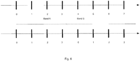
- This implementation is illustrated in the top axis in Fig. 6 in which the frequency band is divided into two bands, i.e. band A and band B, and 8 carrier frequencies are shown. In the top axis a single enumeration is applied and 3 bits are therefore needed for representing a carrier frequency.
- the carrier frequency is indicted as a channel number C
- multiple enumerations are applied over all frequency bands. This can be realized by dividing the spectrum into pre-defined disjoint frequency bands and performing an enumeration independently for each frequency band. Therefore, the frequency spectrum of the wireless communication system 500 is divided into a plurality of non-overlapping frequency bands, and wherein the channel number C is associated with a unique carrier frequency in a frequency band.
- mapping from a channel number to a carrier frequency C ⁇ f C,i is a one-to-many mapping and every value of the channel number C could be associated with more than one frequency f C,i .
- this still provides the receiving device 300 with a unique mapping C ⁇ f C,i since it knows in which frequency band it is detecting the synchronization signal block.
- This implementation is illustrated in the bottom axis in Fig. 6 in which the enumeration is repeated for each band A and B.
- 2 bits are needed in this case for representing a carrier frequency.
- the advantage of this is that fewer bits are needed for encoding the information about the carrier frequency, e.g., a reduction from log 2 N bits to log 2 ( N / M ) when N frequency positions are divided into M frequency bands. It is one objective to minimize the number of bits needed for indicating the carrier frequency, since the number of carrier frequencies may be very large while a large signaling overhead incurs smaller area coverage (i.e., higher code rates) for a given channel. Area coverage is particularly important for channels used for the initial access, such as synchronization signals, broadcast signals and for channels delivering system information.
- carrier frequency is used together with cell ID, e.g., to define a measurement object, further information about the designated frequency band may be needed in order for the receiving device 300 to be able to determine the correct carrier frequency uniquely.
- the channel number C can be indicated using log 2 SC bits in MIB, where SC is the total number of subcarriers within a given frequency band. This gives maximum deployment flexibility at the cost of signaling overhead.
- a frequency spacing between two neighboring synchronization signals is a multiple of a sub-carrier spacing of the wireless communication system 500, and wherein the first frequency raster is a subset of the second frequency raster.
- the distance between two neighboring synchronization signal frequency locations, ⁇ f SS is a multiple of a SubCarrier Spacing (SCS) supported by the wireless communication system 500.
- the synchronization signal frequency locations are a subset of the channel frequencies, i.e., ⁇ f SS,i ⁇ ⁇ ⁇ f C , i ⁇ .
- the carrier frequency is indicated using a relative channel number ⁇ C, i.e. - ( N - 1) ⁇ ⁇ C ⁇ N - 1.
- the receiving device 300 detects the synchronization signal block frequency location f SS,i , which is on the channel raster and determines a relative carrier frequency ⁇ C ⁇ ⁇ f C,i based on a pre-defined mapping rule.
- the carrier frequency is derived based on the relative number, f SS,i + ⁇ f C,i .
- the carrier frequency is indicated using a relative channel number ⁇ C , i.e. - ( N - 1) ⁇ ⁇ C ⁇ N - 1.
- the receiving device 300 is informed of a frequency location f WB , which is on the channel raster and determines a relative carrier frequency ⁇ C ⁇ ⁇ f C,i based on a pre-defined mapping rule.
- the carrier frequency is derived based on the relative number, f WB + ⁇ f C,i .
- the number N could be determined from the maximum carrier bandwidth, i.e., the maximum number of carrier frequencies that could be located within a carrier. It is realized that this would offer a minimum value of N since the carrier frequency could not be located farther away from the synchronization signal block frequency than the carrier bandwidth.
- the maximum carrier bandwidth is W Hz
- the maximum carrier bandwidth may depend on the frequency band, e.g., very wide carriers may be used in higher frequency bands.
- the second raster may be different in different frequency bands. Therefore, the number N could be frequency dependent such as N(f) ⁇ ⁇ W ( f )/
- the number N could be decreased further. For example, suppose that the carrier frequency cannot be located farther away than X Hz (where X is smaller than the maximum carrier bandwidth) from the synchronization signal block frequency f SS,i , it follows that N ⁇ ⁇ X /
- the number N could follow a single enumeration and be derived based on all synchronization signal frequencies in the wireless communication system 500.
- the number N could in another case follow multiple enumerations. This is realized by dividing the spectrum into pre-defined disjoint frequency bands and performing an enumeration independently for each frequency band.
- the mapping ⁇ C ⁇ ⁇ f C,i is a one-to-many mapping and every value ⁇ C could be associated with more than one frequency ⁇ f C,i .
- the advantage of this is that fewer bits need to be used for encoding the information about the carrier frequency, e.g., a reduction from log 2 (2 N + 1) bits to log 2 ( 2N / M ) when N frequency positions are divided into M frequency bands.
- carrier frequency is used together with cell ID, e.g., to define a measurement object, further information about the designated frequency band may be needed in order for the receiving device 300 to uniquely be able to determine the correct carrier frequency.
- the carrier frequency is indicated using a first index and a second index.
- the first index indicates a first frequency location relative to the frequency location of the synchronization signal and the second index indicates a second frequency location relative to the first frequency location indicated by the first index.
- the first frequency location is given in number of PRBs or in a resolution of the first frequency raster.
- the second frequency location is therefore given in a resolution the second frequency raster.
- resolution of a raster it is here meant the frequency spacing between two neighbouring frequencies of the raster.
- the first index -(M - 1) ⁇ ⁇ ⁇ M - 1 therefore determines an offset, e.g., in terms of PRB bandwidth steps B or first frequency raster steps (also denoted SS raster steps, or SS raster resolution), from the detected synchronization signal frequency location wherein the carrier frequency is located.
- the value M determines the number of PRBs or first frequency raster steps ⁇ f SS that could fit into the frequency band. In another realization, the value M determines the number of PRBs or first frequency raster steps ⁇ f SS that could fit into the maximum carrier bandwidth. It is realized that this may reduce the value of M since the distance between the synchronization signal and the carrier frequency cannot be larger than the maximum carrier bandwidth (which may be frequency band dependent).
- the second index provides the location of the carrier frequency within the PRB or within the frequency region confined by two consecutive synchronization signal frequencies. For example, in Fig.
- the carrier frequency is located 3 PRBs (second index) away from the detected synchronization signal block frequency (i.e., f SS,i ) and the carrier frequency is located on the second carrier frequency (first index) from the location derived from the first index.
- This allows reducing the number of bits for representing the carrier frequency, assuming that the first index has steps or granularity which are larger than the second frequency raster and that there is a constraint on how many PRBs or synchronization signal raster positions away from the synchronization signal block frequency that the carrier frequency could be placed, e.g., being limited by the maximum carrier bandwidth.
- the receiving device 300 could determine the PRB frequency locations and/or the RS frequency locations within a carrier, assuming their frequency locations are associated with the carrier frequency. For example, if the system bandwidth is signaled to the receiving device 300 with the carrier frequency and the system bandwidth, the PRB locations within the carrier frequency band can be determined. For each system bandwidth, one PRB location is determined.
- the central frequency of PRB#(Z+1)/2 is aligned with the carrier frequency. In this case, the PRB location is located as illustrated in Fig. 8 (a) . If the total number of PRBs within the frequency band (Z) is even, then the carrier frequency is located between PRB#(Z/2) and PRB#(Z/2+1) and the PRB is located as illustrated in Fig. 8 (b) .
- An advantage of aligning the PRBs from a given frequency (e.g., the carrier frequency) in a carrier is that the PRBs become frequency position aligned between carriers. This enables use of techniques utilizing inter-cell interference coordination.
- the network node herein may also be denoted as a radio network node, an access network node, an access point, or a base station, e.g. a Radio Base Station (RBS), which in some networks may be referred to as transmitter, "eNB”, “eNodeB”, “NodeB” or “B node”, depending on the technology and terminology used.
- the radio network nodes may be of different classes such as e.g. macro eNodeB, home eNodeB or pico base station, based on transmission power and thereby also cell size.
- the radio network node can be a Station (STA), which is any device that contains an IEEE 802.11-conformant Media Access Control (MAC) and Physical Layer (PHY) interface to the Wireless Medium (WM).
- STA Station
- the radio network node may also be a base station corresponding to the fifth generation (5G) wireless systems.
- the client device herein may be denoted as a user device, a User Equipment (UE), a mobile station, an internet of things (loT) device, a sensor device, a wireless terminal and/or a mobile terminal, is enabled to communicate wirelessly in a wireless communication system, sometimes also referred to as a cellular radio system.
- the UEs may further be referred to as mobile telephones, cellular telephones, computer tablets or laptops with wireless capability.
- the UEs in the present context may be, for example, portable, pocket-storable, hand-held, computer-comprised, or vehicle-mounted mobile devices, enabled to communicate voice and/or data, via the radio access network, with another entity, such as another receiver or a server.
- the UE can be a Station (STA), which is any device that contains an IEEE 802.11-conformant Media Access Control (MAC) and Physical Layer (PHY) interface to the Wireless Medium (WM).
- STA Station
- MAC Media Access Control
- PHY Physical Layer
- the UE may also be configured for communication in 3GPP related LTE and LTE-Advanced, in WiMAX and its evolution, and in fifth generation wireless technologies, such as New Radio.
- any method according to embodiments of the invention may be implemented in a computer program, having code means, which when run by processing means causes the processing means to execute the steps of the method.
- the computer program is included in a computer readable medium of a computer program product.
- the computer readable medium may comprise essentially any memory, such as a ROM (Read-Only Memory), a PROM (Programmable Read-Only Memory), an EPROM (Erasable PROM), a Flash memory, an EEPROM (Electrically Erasable PROM), or a hard disk drive.
- the network node and the client device comprises the necessary communication capabilities in the form of e.g., functions, means, units, elements, etc., for performing the present solution.
- means, units, elements and functions are: processors, memory, buffers, control logic, encoders, decoders, rate matchers, de-rate matchers, mapping units, multipliers, decision units, selecting units, switches, interleavers, de-interleavers, modulators, demodulators, inputs, outputs, antennas, amplifiers, receiver units, transmitter units, DSPs, MSDs, TCM encoder, TCM decoder, power supply units, power feeders, communication interfaces, communication protocols, etc. which are suitably arranged together for performing the present solution.
- the processor(s) of the network node and the client device may comprise, e.g., one or more instances of a Central Processing Unit (CPU), a processing unit, a processing circuit, a processor, an Application Specific Integrated Circuit (ASIC), a microprocessor, or other processing logic that may interpret and execute instructions.
- CPU Central Processing Unit
- ASIC Application Specific Integrated Circuit
- microprocessor may thus represent a processing circuitry comprising a plurality of processing circuits, such as, e.g., any, some or all of the ones mentioned above.
- the processing circuitry may further perform data processing functions for inputting, outputting, and processing of data comprising data buffering and device control functions, such as call processing control, user interface control, or the like.
Description
- The invention relates to a transmitting device and a receiving device. Furthermore, the invention also relates to corresponding methods.
- In 3GPP New Radio (NR), a Synchronization Signal (SS) block comprises NR-Primary Synchronization Signal (NR-PSS), NR-Secondary Synchronization Signal (NR-SSS) and NR-Physical Broadcast Channel (NR-PBCH). After detecting a synchronization signal block, a User Equipment (UE) is able to synchronize to a cell and obtain a cell ID of the cell as well as obtaining broadcast information. The broadcast information, e.g., the NR-Master Information Block (NR-MIB), may further contain information making it possible for the UE to detect the NR-Physical Downlink Shared Channel (NR-PDSCH) for obtaining system information, e.g., Remaining System Information (RMSI) and Other System Information (OSI). The NR-PBCH may include information about control channel resources wherein the UE may detect a NR-Physical Downlink Control Channel (NR-PDCCH) which is scheduling the RMSI through the NR-PDSCH. The NR-PBCH should be received over a large coverage area and therefore its payload should be minimized. Additional system information may be contained in the RMSI or the OSI.
- In 3GPP NR, the synchronization signal block is located on a frequency raster (e.g., the center frequency of the SS block or the SS is on the raster), i.e., a set of frequencies with a predefined spacing between them. The frequency raster used for the synchronization signal block, herein denoted the synchronization signal raster, may be different from the frequency raster used for the NR channels, herein denoted the NR channel raster. The NR channel raster defines the carrier frequencies (e.g., the center frequency of a carrier) available for deploying an NR carrier. A carrier should be understood as an entity of the communication system which comprises channels and signals used for communications and carriers could be deployed in both downlink and uplink communications.
- The synchronization signal raster and the NR channel raster may be selected for different purposes. Hence, the synchronization signal raster may, e.g., be sparser than the NR channel raster to reduce the search complexity for the UE. At least for initial cell selection, the UE searches for synchronization signals on the synchronization signal raster. The synchronization signal raster could, e.g., be a multiple of 15 kHz, which is a SubCarrier Spacing (SCS) in NR, say 300 kHz or 900 kHz. The NR system will provide different SCS, e.g., the SS may use 15, 30, 120 or 240 kHz SCS. Additional SCS such as 60 kHz may be applicable to other channels and signals. In addition, the synchronization signal raster may be different in different frequency bands, e.g., it could be 100 kHz in bands where LTE and NR should coexist. Similarly, the NR channel raster may be different in different frequency bands, e.g., it could be 100 kHz in bands where LTE and NR should coexist and could assume larger values in high frequency bands, where the amount of spectrum is much larger.
- If the synchronization signal raster and NR channel raster are different, it is realized that the synchronization signal block may not be located around the center frequency of the NR carrier, e.g., the carrier frequency. Moreover, an NR carrier may include multiple synchronization signal blocks transmitted at different frequency locations. Hence, the synchronization signal raster could give synchronization signal frequency locations which are a subset of the channel frequencies, or which are not at all aligned with the channel frequencies or which are partly aligned with the channel frequencies.
- In the conventional system 3GPP LTE, the synchronization signals are located around the center frequency of the carrier and the synchronization signal raster is the same as the channel raster. Hence, the UE could determine the carrier frequency implicitly from the detected frequency position of the synchronization signal. The carrier frequency information allows the UE to achieve one or several of the following non-limiting tasks:
- Tune its oscillator to the carrier frequency.
- Perform receiver filtering.
- Perform mobility measurements on cells characterized by both cell ID and the carrier frequency.
- Detect multiple synchronization signal blocks and determine which carrier they belong to.
- Determine the Physical Resource Block (PRB) locations of the carrier.
- Determine the locations of reference signals (RSs).
- Receive system information.
- In 3GPP NR, on the other hand, the UE will not be able to determine the carrier frequency implicitly from the detected synchronization signal block as the synchronization signal raster and the NR channel raster may be different. Hence, there is an issue on how to determine the NR carrier frequency in 3GPP NR.
- ZTE: "Multiple SS blocks in wideband CC", 3GPP Draft;
R1 1709887, 3RD GENERATION PARTNERSHIP PROJECT, discloses techniques for number of SS blocks in the frequency domain. - An objective of embodiments of the invention is to provide a solution which mitigates or solves the drawbacks and problems of conventional solutions.
- The above and further objectives are solved by the subject matter of the independent claims. Further advantageous implementation forms of the present invention can be found in the dependent claims.
- According to a first aspect of the invention, the above mentioned and other objectives are achieved with a transmitting device for a wireless communication system, according to
claim 1. - In one implementation of the first aspect, a frequency band in which the carrier is located comprises values determined from the first raster and the second raster, where values represent a frequency location.
- A frequency raster in this disclosure can be understood to be a set of frequencies with a predefined spacing between them. The first frequency raster can be aligned or not be aligned with the second frequency raster. The frequency raster may be frequency dependent, i.e., different frequency rasters could be used in different frequency bands.
- The transmitting device according to the first aspect relates to the case where there can be more than one synchronization signal in a carrier. In that case, the synchronization signals are located on different frequency positions on the first frequency raster. This does not however preclude the case that there is only one synchronization signal in the carrier. It is further noted that there could be multiple types of synchronization signals, such as primary synchronization signals, secondary synchronization signals, etc. Therefore, the one or more synchronization signal can comprise different types of synchronization signals herein. It should be further understood that the case where more than one synchronization signal is provided in a carrier and where the synchronization signals are located on different frequency positions on the first frequency raster, includes the case that one synchronization signal may comprise different types of synchronization signals (e.g., an NR-PSS and an NR-SSS) which are separated in time (e.g., in different OFDM symbols) but use the same frequency location (i.e., same raster value). Hence, one example is that a first pair of synchronization signals, NR-PSS_1 and NR-SSS_1, have the same frequency location, which is different from that one of a second pair of synchronization signals, NR-PSS_2 and NR-SSS_2. Furthermore, it should be understood that a carrier may also only comprise a first pair of synchronization signals, NR-PSS_1 and NR-SSS_1, which have the same frequency location.
- It should further be noted that the carrier frequency may or may not be equal to the center frequency of the carrier. For a receiving device not capable of receiving a wideband carrier, it could transmit and/or receive on one part of the carrier. Such a part of a wideband carrier could be regarded as the carrier for a certain receiving device, wherein its carrier frequency is confined to be within the part of the wideband carrier, which may not be the central frequency of the carrier.
- A transmitting device according to the first aspect provides a number of advantages over conventional solutions. An advantage of the transmitting device is that it allows the receiving device to determine the carrier frequency and potentially either/both of the frequency location of the synchronization signal within the carrier and the PRB and Reference Signal (RS) frequency locations.
- In an implementation form of a transmitting device according to the first aspect, the frequency of the synchronization signal is a center frequency of the synchronization signal or of the carrier. In one example, the center frequency and the carrier frequency are different frequencies.
- In an implementation form of a transmitting device according to the first aspect, the at least one integer number is a channel number.
- An advantage with this implementation form is that it reduces the signalling overhead of indicating the carrier frequency since the mapping between a carrier frequency and channel number could be known. Furthermore, the carrier frequency can be determined uniquely from a channel number.
- In an implementation form of a transmitting device according to the first aspect, the channel number is associated with a unique carrier frequency.
- An advantage with this implementation form is that this would provide a simple way to unambiguously determine the carrier frequency, which reduces the receiver complexity.
- In an implementation form of a transmitting device according to the first aspect, a frequency spectrum of the wireless communication system is divided into a plurality of non-overlapping frequency bands, and wherein the channel number is associated with a unique carrier frequency in a frequency band.
- An advantage with this implementation form is that fewer bits are needed for encoding the information about the carrier frequency since the range of channel number values could be reduced.
- In an implementation form of a transmitting device according to the first aspect, a range of the channel number depends on the frequency band.
- An advantage with this implementation form is that the signalling overhead of the channel number could be reduced. For example, in frequency bands where there is a large amount of spectrum available, the frequency raster may contain few frequencies and consequently, few channel numbers.
- In an implementation form of a transmitting device according to the first aspect, a frequency spacing between two neighbouring synchronization signals is a multiple of a sub-carrier spacing of the wireless communication system, and the first frequency raster is a subset of the second frequency raster.
- An advantage with this implementation form is that the synchronization signals align with the subcarriers of the other channels and signals of the carrier.
- In an implementation form of a transmitting device according to the first aspect, the at least one integer number is a relative channel number.
- An advantage with this implementation form is that it is possible to further reduce the overhead of signalling the carrier frequency.
- In an implementation form of a transmitting device according to the first aspect, the relative channel number is dependent on a maximum carrier bandwidth of the wireless communication system.
- An advantage with this implementation form is that it is possible to further reduce the overhead of signalling the carrier frequency considering that the synchronization signal could not be located farther away from the carrier frequency than the maximum carrier bandwidth.
- In an implementation form of a transmitting device according to the first aspect, a range of the relative channel number is dependent on the maximum carrier bandwidth.
- An advantage with this implementation form is that it is possible to further reduce the overhead of signalling the carrier frequency considering that the synchronization signal could not be located farther away from the carrier frequency than the maximum carrier bandwidth.
- In an implementation form of a transmitting device according to the first aspect, the maximum carrier bandwidth is frequency dependent.
- An advantage with this implementation form is that a wider carrier bandwidth is only provided in frequency bands where there is large amount of spectrum available.
- In an implementation form of a transmitting device according to the first aspect, the at least one integer number is a first index indicating a first frequency location relative to the frequency of the synchronization signal and a second index indicating a second frequency location relative to the first frequency location.
- An advantage with this implementation form is that it is possible to further reduce the overhead of signalling the carrier frequency.
- In an implementation form of a transmitting device according to the first aspect, the first frequency location is given in number of physical resource blocks, and the second frequency location is given in a resolution of the second frequency raster.
- An advantage with this implementation form is that it is possible to further reduce the overhead of signalling the carrier frequency and that the synchronization signals may be aligned in frequency position with the other channels and signals being located in resource blocks.
- In an implementation form of a transmitting device according to the first aspect, the first frequency location is given in a resolution of the first frequency raster, and the second frequency location is given in a resolution of the second frequency raster.
- An advantage with this implementation form is that it is possible to further reduce the overhead of signalling the carrier frequency considering that the first raster may be sparser than the second raster.
- In an implementation form of a transmitting device according to the first aspect, the transmitting device is further configured to
transmit the indication in at least one of: Master Information Block (MIB), Remaining System Information (RMSI), Other System Information (OSI), and Radio Resource Control (RRC). - An advantage with this implementation form is that the signalling is made in channels which have the capability to contain more information that what the synchronization signal can do. Encoding additional information in the synchronization signals, increase the receiver complexity, since they are typically based on synchronization sequences, while the MIB, RMSI, OSI and RRC signalling are carried in channels better suited for information transmission.
- According to a second aspect of the invention, the above mentioned and other objectives are achieved with receiving device for a wireless communication system, according to claim 14.
- In one implementation of the second aspect, a frequency band in which the carrier is located comprises values determined from the first raster and the second raster.
- A receiving device according to the second aspect provides a number of advantages over conventional solutions. An advantage is that it allows the receiving device to determine the carrier frequency and potentially either/both of the frequency location of the synchronization signal within the carrier and the PRB and RS frequency locations.
- In an implementation form of a receiving device according to the second aspect, a frequency spectrum of the wireless communication system is divided into a plurality of non-overlapping frequency bands, and the at least one integer number is associated with a frequency band, the receiving device is further configured to
map the at least one integer number based on the frequency band so as to derive the carrier frequency. - According to a third aspect of the invention, the above mentioned and other objectives are achieved with a method for a transmitting device, according to claim 19.
- In one implementation of the third aspect, a frequency band in which the carrier is located comprises values determined from the first raster and the second raster.
- In one implementation of the third aspect, the method further comprises obtaining at least one synchronization signal previous to transmitting the at least one synchronization signal.
- The method according to the third aspect can be extended into implementation forms corresponding to the implementation forms of the transmitting device according to the first aspect. Hence, an implementation form of the method comprises the feature(s) of the corresponding implementation form of the transmitting device.
- The advantages of the methods according to the third aspect are the same as those for the corresponding device claims according to the first aspect.
- According to a fourth aspect of the invention, the above mentioned and other objectives are achieved with a method for a receiving device, according to claim 25.
- In one implementation of the fourth aspect, a frequency band in which the carrier is located comprises values determined from the first raster and the second raster.
- The method according to the fourth aspect can be extended into implementation forms corresponding to the implementation forms of the receiving device according to the second aspect. Hence, an implementation form of the method comprises the feature(s) of the corresponding implementation form of the receiving device.
- The advantages of the methods according to the fourth aspect are the same as those for the corresponding device claims according to the second aspect.
- Further applications and advantages of the present invention will be apparent from the following detailed description.
- The appended drawings are intended to clarify and explain different embodiments of the present invention, in which:
-
Fig. 1 shows a transmitting device according to an implementation form of the invention; -
Fig. 2 shows a method according to an implementation form of the invention; -
Fig. 3 shows a receiving device according to an implementation form of the invention; -
Fig. 4 shows another method according to an implementation form of the invention; -
Fig. 5 shows a wireless system according to an implementation form of the invention; -
Fig. 6 shows enumeration of the carrier frequency according to implementation forms of the invention; -
Fig. 7 shows indication of the carrier frequency by using a first index and a second index according to an implementation form of the invention. -
Fig. 8 a) and b) shows PRB grids within the frequency band according to implementation forms of the invention. -
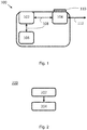
Fig. 1 shows a transmittingdevice 100 according to an implementation form of the invention. In the implementation shown inFig. 1 , the transmittingdevice 100 comprises aprocessor 102, atransceiver 104 and amemory 106. Theprocessor 102 is coupled to thetransceiver 104 and thememory 106 by communication means 108 known in the art. The transmittingdevice 100 may be configured for both wireless and wired communications in wireless and wired communication systems, respectively. The wireless communication capability is provided with anantenna 110 coupled to thetransceiver 104, while the wired communication capability is provided with awired communication interface 112 coupled to thetransceiver 104. - That the transmitting
device 100 is configured to perform certain actions and/or functions according to the invention should in this disclosure be understood to mean that the transmittingdevice 100 comprises suitable means, such as e.g. theprocessor 102 and thetransceiver 104, configured to perform said actions and/or functions. - The transmitting
device 100 inFig. 1 is configured to transmit one or more synchronization signals (SSs) on a carrier to at least onereceiving device 300, wherein a frequency of a synchronization signal among the one or more synchronization signals is located on a first frequency raster and a carrier frequency of the carrier is deployed on a second frequency raster, and wherein frequencies of two different synchronization signals among the one or more synchronization signals are located on different frequency positions in the first raster. The transmittingdevice 100 is further configured to transmit an indication of the carrier frequency to the at least onereceiving device 300. The indication herein comprises at least one integer number. -
Fig. 2 shows a flow chart of acorresponding method 200 which may be executed in atransmitting device 100, such as the one shown inFig. 1 . Themethod 200 comprises transmitting 202 one or more synchronization signals on a carrier to at least onereceiving device 300, wherein a frequency of a synchronization signal among the one or more synchronization signals is located on a first frequency raster and a carrier frequency of the carrier is deployed on a second frequency raster, and wherein frequencies of two different synchronization signals among the one or more synchronization signals are located on different frequency positions in the first raster. The method further comprises transmitting 204 an indication of the carrier frequency to the at least onereceiving device 300. The indication comprises at least one integer number. -
Fig. 3 shows a receivingdevice 300 according to an implementation form of the invention. In the implementation shown inFig. 3 , the receivingdevice 300 comprises aprocessor 302, atransceiver 304 and amemory 306. Theprocessor 302 is coupled to thetransceiver 304 and thememory 306 by communication means 308 known in the art. The receivingdevice 300 further comprises anantenna 308 coupled to thetransceiver 302, which means that the receivingdevice 300 is configured for wireless communications in a wireless communication system. - That the receiving
device 300 is configured to perform certain actions and/or functions according to the invention should in this disclosure be understood to mean that the receivingdevice 300 comprises suitable means, such as e.g. theprocessor 302 and thetransceiver 304, configured to perform said actions and/or functions. - The receiving
device 300 is configured to receive one or more synchronization signals on a carrier from a transmittingdevice 100, wherein a frequency of a synchronization signal among the one or more synchronization signals is located on a first frequency raster and a carrier frequency of the carrier is deployed on a second frequency raster, and wherein frequencies of two different synchronization signals among the one or more synchronization signals are located on different frequency positions in the first raster. The receivingdevice 300 is further configured to receive an indication of the carrier frequency from the transmittingdevice 100, wherein the indication comprises at least one integer number. The receivingdevice 300 is further configured to derive the carrier frequency based on the at least one integer number. Examples of how the carrier frequency is derived from the at least one integer number is explained in the following disclosure. -
Fig. 4 shows a flow chart of acorresponding method 400 which may be executed in areceiving device 300, such as the one shown inFig. 3 . Themethod 400 comprises receiving 402 one or more synchronization signals on a carrier from a transmittingdevice 100, wherein a frequency of a synchronization signal among the one or more synchronization signals is located on a first frequency raster and a carrier frequency of the carrier is deployed on a second frequency raster, and wherein frequencies of two different synchronization signals among the one or more synchronization signals are located on different frequency positions in the first raster. Themethod 400 further compromises receiving 404 an indication of the carrier frequency from the transmittingdevice 100, wherein the indication comprises at least one integer number. Themethod 400 further comprises deriving 406 the carrier frequency based on the at least one integer number. -
Fig. 5 shows awireless communication system 500 according to an implementation of the invention. Thewireless communication system 500 comprises a transmittingdevice 100 and areceiving device 300 configured to operate in thewireless communication system 500. In this example, the downlink (DL) case is illustrated which means that the transmittingdevice 100 is part of a network node (such as a base station) whilst the receivingdevice 300 is part of a client device (such as a UE). In thewireless communication system 500, synchronization signals (SSs) are transmitted by the transmittingdevice 100 and received by the receivingdevice 300. For simplicity, thewireless communication system 500 shown inFig. 5 only comprises onetransmitting device 100 and onereceiving device 300. However, thewireless communication system 500 may comprise any number of transmitting devices and any number of receiving devices without deviating from the scope of the invention. - It is to be noted that the present solution is not limited to the downlink case and can therefore be implemented in the uplink (UL) or both in the downlink and the uplink. Hence, the transmitting
device 100 and the receivingdevice 300 may be associated with a network node and/or a client device depending on the implementation case. - In one example, the frequency spectrum of the
wireless communication system 500 is divided into a plurality of non-overlapping frequency bands, and the at least one integer number is associated with a frequency band. In this case, the receivingdevice 300 is configured to map the at least one integer number based on the frequency band so as to derive the carrier frequency. - The indication of the carrier frequency herein could be signaled by the transmitting
device 100 to the receivingdevice 300 using several different methods, e.g., depending on when during the access procedure the receivingdevice 300 needs to be aware of the carrier frequency. The transmittingdevice 100 is hence configured to transmit the indication in at least one of: a Master Information Block (MIB), Remaining System Information (RMSI), Other System Information (OSI), and Radio Resource Control (RRC). - The MIB offers the quickest way of delivering the carrier frequency information in a broadcast channel. On the other hand, it is beneficial to minimize the payload of the broadcast channel.
- The RMSI can be contained in the NR-PDSCH which is scheduled by the NR-PDCCH, where information related to the configuration of the NR-PDCCH/NR-PDSCH are contained in the NR-MIB. If the carrier frequency information is contained in the RMSI, it implies that the RMSI should be detectable without knowing the carrier frequency. Hence, resources in NR-PDCCH/NR-PDSCH for determining RMSI should not depend on the carrier frequency but may be determined from the NR-SS and/or NR-PBCH.
- The OSI can be contained in the NR-PDSCH which is scheduled by the NR-PDCCH, where information related to the configuration of the NR-PDCCH/NR-PDSCH are contained in the NR-MIB and/or the RMSI. If the carrier frequency information is contained in the OSI, it implies that the OSI should be detectable without knowing the carrier frequency. Hence, resources in NR-PDCCH/NR-PDSCH for determining OSI should not depend on the carrier frequency but may be determined from the NR-SS and/or NR-PBCH.
- The invention is also applicable if the indication of the carrier frequency is jointly transmitted by any of the NR-MIB, RMSI and OSI.
- When RRC signaling is used for signaling and the carrier frequency is used to define cells in higher layers for mobility measurements, a cell description comprising both cell ID and carrier frequency could be signaled by RRC. In this case, the overhead of signaling the carrier frequency is less critical since RRC signaling is carried by the NR-PDSCH.
- In the following, possible implementation forms of the invention are described and explained. In this respect a
wireless communication system 500 where synchronization signals could be placed on a first frequency raster {fSS,i } (i.e., a set of frequencies) resulting in a minimum separation of |fSS,i - f SS,i+1| = ΔfSS Hz and where carriers could be placed on a second frequency raster {fC,i } resulting in a minimum separation of |fC,i - f C,i+1| = ΔfC Hz, is considered. The first frequency raster and the second frequency raster could in such a system be frequency band dependent, i.e., the values ΔfSS (fSS,i ) and ΔfC (fC,i ) representing the frequency spacing may not be constants and could be a function of the frequency. It is however noted that the invention is not limited to the above described type of wireless communication system. - In one implementation of the invention, the carrier frequency is indicted as a channel number C. In this case the mapping from a channel number to a carrier frequency, C → fC,i, could be pre-defined and be known to the receiving
device 300. As an example, the mapping could be performed using a closed form expression, such as: FDL = FDL_low + ΔfC (C - N Offs_DL ), where the constants FDL_low and N Offs_DL can be predefined and FDL = fC,i. - In one realization, N channel frequencies

- In one example when the carrier frequency is indicted as a channel number C, a single enumeration is applied over all frequency bands which means that each channel number is associated with a unique carrier frequency. That is, the mapping of a channel number to a carrier frequency C → fC,i is a one-to-one mapping and every value of the channel number C is associated with a unique frequency fC,i . This implementation is illustrated in the top axis in
Fig. 6 in which the frequency band is divided into two bands, i.e. band A and band B, and 8 carrier frequencies are shown. In the top axis a single enumeration is applied and 3 bits are therefore needed for representing a carrier frequency. This would provide a simple way to unambiguously determine the carrier frequency but requires the size N of the set of channel numbers to encompass all carrier frequencies of the system. The mapping could be frequency band specific and pre-defined, e.g., FDL = FDL_low + ΔfC (C)(C - NOffs_DL ), where the raster value is a function of the channel number, i.e. ΔfC (C). - In another example when the carrier frequency is indicted as a channel number C, multiple enumerations are applied over all frequency bands. This can be realized by dividing the spectrum into pre-defined disjoint frequency bands and performing an enumeration independently for each frequency band. Therefore, the frequency spectrum of the
wireless communication system 500 is divided into a plurality of non-overlapping frequency bands, and wherein the channel number C is associated with a unique carrier frequency in a frequency band. - Hence, the mapping from a channel number to a carrier frequency C → fC,i is a one-to-many mapping and every value of the channel number C could be associated with more than one frequency fC,i. However, this still provides the receiving
device 300 with a unique mapping C → fC,i since it knows in which frequency band it is detecting the synchronization signal block. It is noted however that the mapping may be different in different frequency bands, e.g., the mapping could be frequency band specific and pre-defined, e.g., FDL = FDL_low + ΔfC (C)(C - NOffs_DL ), where the raster value is a function of the channel number, ΔfC ( C ). This implementation is illustrated in the bottom axis inFig. 6 in which the enumeration is repeated for each band A and B. Hence, 2 bits are needed in this case for representing a carrier frequency. The advantage of this is that fewer bits are needed for encoding the information about the carrier frequency, e.g., a reduction from log2 N bits to log2(N /M) when N frequency positions are divided into M frequency bands. It is one objective to minimize the number of bits needed for indicating the carrier frequency, since the number of carrier frequencies may be very large while a large signaling overhead incurs smaller area coverage (i.e., higher code rates) for a given channel. Area coverage is particularly important for channels used for the initial access, such as synchronization signals, broadcast signals and for channels delivering system information. When carrier frequency is used together with cell ID, e.g., to define a measurement object, further information about the designated frequency band may be needed in order for the receivingdevice 300 to be able to determine the correct carrier frequency uniquely. - In one implementation, the channel number C can be indicated using log2 SC bits in MIB, where SC is the total number of subcarriers within a given frequency band. This gives maximum deployment flexibility at the cost of signaling overhead.
- Further possible implementations of the invention apply when a frequency spacing between two neighboring synchronization signals is a multiple of a sub-carrier spacing of the
wireless communication system 500, and wherein the first frequency raster is a subset of the second frequency raster. In other words, the distance between two neighboring synchronization signal frequency locations, ΔfSS , is a multiple of a SubCarrier Spacing (SCS) supported by thewireless communication system 500. Further, the synchronization signal frequency locations are a subset of the channel frequencies, i.e., {fSS,i } ⊆ {fC,i }. Herein, a multiple of a SCS may include the case where the distance between two synchronization signal frequency locations, ΔfSS , is a multiple n of a PRB bandwidth B (which is also a multiple of a SCS) for a certain given SCS, ΔfSS = n · B, where n is a positive integer. - In one implementation when the above assumptions hold, it is disclosed here that the carrier frequency is indicated using a relative channel number ΔC, i.e. -(N - 1) ≤ ΔC ≤ N - 1. In this case the receiving
device 300 detects the synchronization signal block frequency location fSS,i , which is on the channel raster and determines a relative carrier frequency ΔC → ΔfC,i based on a pre-defined mapping rule. For example, ΔfC,i may be a multiple of the carrier frequency raster, ΔfC = |fC,i - f C,i+1|. The carrier frequency is derived based on the relative number, fSS,i + ΔfC,i . Since {fSS,i } ⊆ {fC,i }, it follows that fSS,i + ΔfC,i ⊆ {fC,i } The number of bits to represent the relative channel number could be log2(2N + 1) where N is the number of synchronization signal frequencies. - In another implementation when the above assumptions hold, it is disclosed here that the carrier frequency is indicated using a relative channel number ΔC, i.e. -(N - 1) ≤ ΔC ≤ N - 1. In this case the receiving
device 300 is informed of a frequency location fWB , which is on the channel raster and determines a relative carrier frequency ΔC → ΔfC,i based on a pre-defined mapping rule. For example, ΔfC,i may be a multiple of the carrier frequency raster, ΔfC = |fC,i - f C,i+1| . The carrier frequency is derived based on the relative number, fWB + ΔfC,i . Since fWB ∈ {fC,i }. it follows that fWB + ΔfC,i ⊆ {fC,i }. The number of bits to represent the relative channel number could be log2(2N + 1) where N is the number of channel rasters on this frequency band. - It is realized that one advantage is that the number N could be determined from the maximum carrier bandwidth, i.e., the maximum number of carrier frequencies that could be located within a carrier. It is realized that this would offer a minimum value of N since the carrier frequency could not be located farther away from the synchronization signal block frequency than the carrier bandwidth. For example, suppose that the maximum carrier bandwidth is W Hz, it follows that N ≤ ┌W/|fC,i - f C,i+1|┐, utilizing the ceiling operator, such that ┌x┐ denotes the smallest integer being larger than x. Furthermore, the maximum carrier bandwidth may depend on the frequency band, e.g., very wide carriers may be used in higher frequency bands. Also, the second raster may be different in different frequency bands. Therefore, the number N could be frequency dependent such as N(f) ≤ ┌W(f)/|fC,i - f C,i+1|┐.
- If other restrictions could be assumed, in addition to requiring placement on the first raster, on the location the synchronization signal block(s) within the carrier, the number N could be decreased further. For example, suppose that the carrier frequency cannot be located farther away than X Hz (where X is smaller than the maximum carrier bandwidth) from the synchronization signal block frequency fSS,i , it follows that N ≤ ┌X/|fC,i - f C,i+1|┐.
- The number N could follow a single enumeration and be derived based on all synchronization signal frequencies in the
wireless communication system 500. - The number N could in another case follow multiple enumerations. This is realized by dividing the spectrum into pre-defined disjoint frequency bands and performing an enumeration independently for each frequency band. Hence, the mapping ΔC → ΔfC,i is a one-to-many mapping and every value ΔC could be associated with more than one frequency ΔfC,i . However, this still provides the receiving
device 300 with a unique mapping ΔC → fC,i since it knows in which frequency band it is detecting the synchronization signal block. The advantage of this is that fewer bits need to be used for encoding the information about the carrier frequency, e.g., a reduction from log2(2N + 1) bits to log2(2N/M) when N frequency positions are divided into M frequency bands. When carrier frequency is used together with cell ID, e.g., to define a measurement object, further information about the designated frequency band may be needed in order for the receivingdevice 300 to uniquely be able to determine the correct carrier frequency. - In another implementation of the invention when the above assumptions hold, the carrier frequency is indicated using a first index and a second index. The first index indicates a first frequency location relative to the frequency location of the synchronization signal and the second index indicates a second frequency location relative to the first frequency location indicated by the first index.
- In possible implementations of the invention, the first frequency location is given in number of PRBs or in a resolution of the first frequency raster. The second frequency location is therefore given in a resolution the second frequency raster. By resolution of a raster, it is here meant the frequency spacing between two neighbouring frequencies of the raster.
- In one realization of this implementation, it is assumed that the distance between two synchronization signal frequency locations, ΔfSS , is a multiple n of a PRB bandwidth B for a certain given SCS, ΔfSS = n · B, where n is a positive integer. The first index -(M - 1) ≤ δ ≤ M - 1 therefore determines an offset, e.g., in terms of PRB bandwidth steps B or first frequency raster steps (also denoted SS raster steps, or SS raster resolution), from the detected synchronization signal frequency location wherein the carrier frequency is located. In one realization, the value M determines the number of PRBs or first frequency raster steps ΔfSS that could fit into the frequency band. In another realization, the value M determines the number of PRBs or first frequency raster steps ΔfSS that could fit into the maximum carrier bandwidth. It is realized that this may reduce the value of M since the distance between the synchronization signal and the carrier frequency cannot be larger than the maximum carrier bandwidth (which may be frequency band dependent). The second index provides the location of the carrier frequency within the PRB or within the frequency region confined by two consecutive synchronization signal frequencies. For example, in
Fig. 7 , the carrier frequency is located 3 PRBs (second index) away from the detected synchronization signal block frequency (i.e., fSS,i ) and the carrier frequency is located on the second carrier frequency (first index) from the location derived from the first index. This allows reducing the number of bits for representing the carrier frequency, assuming that the first index has steps or granularity which are larger than the second frequency raster and that there is a constraint on how many PRBs or synchronization signal raster positions away from the synchronization signal block frequency that the carrier frequency could be placed, e.g., being limited by the maximum carrier bandwidth. - One consequence of the invention is that, once the receiving
device 300 has determined the carrier frequency, it could determine the PRB frequency locations and/or the RS frequency locations within a carrier, assuming their frequency locations are associated with the carrier frequency. For example, if the system bandwidth is signaled to the receivingdevice 300 with the carrier frequency and the system bandwidth, the PRB locations within the carrier frequency band can be determined. For each system bandwidth, one PRB location is determined. - In one example, if the total number of PRBs within the frequency band Z is odd, then the central frequency of PRB#(Z+1)/2 is aligned with the carrier frequency. In this case, the PRB location is located as illustrated in
Fig. 8 (a) . If the total number of PRBs within the frequency band (Z) is even, then the carrier frequency is located between PRB#(Z/2) and PRB#(Z/2+1) and the PRB is located as illustrated inFig. 8 (b) . - An advantage of aligning the PRBs from a given frequency (e.g., the carrier frequency) in a carrier is that the PRBs become frequency position aligned between carriers. This enables use of techniques utilizing inter-cell interference coordination.
- The network node herein may also be denoted as a radio network node, an access network node, an access point, or a base station, e.g. a Radio Base Station (RBS), which in some networks may be referred to as transmitter, "eNB", "eNodeB", "NodeB" or "B node", depending on the technology and terminology used. The radio network nodes may be of different classes such as e.g. macro eNodeB, home eNodeB or pico base station, based on transmission power and thereby also cell size. The radio network node can be a Station (STA), which is any device that contains an IEEE 802.11-conformant Media Access Control (MAC) and Physical Layer (PHY) interface to the Wireless Medium (WM). The radio network node may also be a base station corresponding to the fifth generation (5G) wireless systems.
- The client device herein may be denoted as a user device, a User Equipment (UE), a mobile station, an internet of things (loT) device, a sensor device, a wireless terminal and/or a mobile terminal, is enabled to communicate wirelessly in a wireless communication system, sometimes also referred to as a cellular radio system. The UEs may further be referred to as mobile telephones, cellular telephones, computer tablets or laptops with wireless capability. The UEs in the present context may be, for example, portable, pocket-storable, hand-held, computer-comprised, or vehicle-mounted mobile devices, enabled to communicate voice and/or data, via the radio access network, with another entity, such as another receiver or a server. The UE can be a Station (STA), which is any device that contains an IEEE 802.11-conformant Media Access Control (MAC) and Physical Layer (PHY) interface to the Wireless Medium (WM). The UE may also be configured for communication in 3GPP related LTE and LTE-Advanced, in WiMAX and its evolution, and in fifth generation wireless technologies, such as New Radio.
- Furthermore, any method according to embodiments of the invention may be implemented in a computer program, having code means, which when run by processing means causes the processing means to execute the steps of the method. The computer program is included in a computer readable medium of a computer program product. The computer readable medium may comprise essentially any memory, such as a ROM (Read-Only Memory), a PROM (Programmable Read-Only Memory), an EPROM (Erasable PROM), a Flash memory, an EEPROM (Electrically Erasable PROM), or a hard disk drive.
- Moreover, it is realized by the skilled person that the network node and the client device comprises the necessary communication capabilities in the form of e.g., functions, means, units, elements, etc., for performing the present solution. Examples of other such means, units, elements and functions are: processors, memory, buffers, control logic, encoders, decoders, rate matchers, de-rate matchers, mapping units, multipliers, decision units, selecting units, switches, interleavers, de-interleavers, modulators, demodulators, inputs, outputs, antennas, amplifiers, receiver units, transmitter units, DSPs, MSDs, TCM encoder, TCM decoder, power supply units, power feeders, communication interfaces, communication protocols, etc. which are suitably arranged together for performing the present solution.
- Especially, the processor(s) of the network node and the client device may comprise, e.g., one or more instances of a Central Processing Unit (CPU), a processing unit, a processing circuit, a processor, an Application Specific Integrated Circuit (ASIC), a microprocessor, or other processing logic that may interpret and execute instructions. The expression "processor" may thus represent a processing circuitry comprising a plurality of processing circuits, such as, e.g., any, some or all of the ones mentioned above. The processing circuitry may further perform data processing functions for inputting, outputting, and processing of data comprising data buffering and device control functions, such as call processing control, user interface control, or the like.
- Finally, it should be understood that the invention is not limited to the embodiments described above, but also relates to and incorporates all embodiments within the scope of the appended independent claims.
Claims (30)
- A transmitting device (100) for a wireless communication system (500), the transmitting device (100) being configured to
transmit one or more synchronization signals on a carrier to at least one receiving device (300), wherein a frequency of a synchronization signal among the one or more synchronization signals is located on a first frequency raster and a carrier frequency of the carrier is deployed on a second frequency raster, and wherein frequencies of two different synchronization signals among the one or more synchronization signals are located on different frequency positions in the first raster;
transmit an indication of the carrier frequency to the at least one receiving device (300), wherein the indication comprises at least one integer number; and
wherein a frequency spacing between two neighbouring synchronization signals is a multiple of a sub-carrier spacing of the wireless communication system (500), and wherein the first frequency raster is a subset of the second frequency raster. - The transmitting device (100) according to claim 1, wherein the at least one integer number is a channel number.
- The transmitting device (100) according to claim 2, wherein the channel number is associated with a unique carrier frequency.
- The transmitting device (100) according to claim 2 or 3, wherein a frequency spectrum of the wireless communication system (500) is divided into a plurality of non-overlapping frequency bands, and wherein the channel number is associated with a unique carrier frequency in a frequency band.
- The transmitting device (100) according to claim 4, wherein a range of the channel number depends on the frequency band.
- The transmitting device (100) according to claim 1, wherein the at least one integer number is a relative channel number.
- The transmitting device (100) according to claim 6, wherein the relative channel number is dependent on a maximum carrier bandwidth of the wireless communication system (500).
- The transmitting device (100) according to claim 7, wherein a range of the relative channel number is dependent on the maximum carrier bandwidth.
- The transmitting device (100) according to claim 7 or 8, wherein the maximum carrier bandwidth is frequency dependent.
- The transmitting device (100) according to claim 1, wherein the at least one integer number is a first index indicating a first frequency location relative to the frequency of the synchronization signal and a second index indicating a second frequency location relative to the first frequency location.
- The transmitting device (100) according to claim 10, wherein the first frequency location is given in number of physical resource blocks, and wherein the second frequency location is given in a resolution of the second frequency raster.
- The transmitting device (100) according to claim 10, wherein the first frequency location is given in a resolution of the first frequency raster, and wherein the second frequency location is given in a resolution of the second frequency raster.
- The transmitting device (100) according to any of the preceding claims, configured to transmit the indication in at least one of: a Master Information Block , MIB, Remaining System Information, RMSI, Other System Information, OSI, and Radio Resource Control , RRC.
- A receiving device (300) for a wireless communication system (500), the receiving device (300) being configured to
receive one or more synchronization signals on a carrier from a transmitting device (100), wherein a frequency of a synchronization signal among the one or more synchronization signals is located on a first frequency raster and a carrier frequency of the carrier is deployed on a second frequency raster, and wherein frequencies of two different synchronization signals among the one or more synchronization signals are located on different frequency positions in the first raster;
receive an indication of the carrier frequency from the transmitting device (100), wherein the indication comprises at least one integer number;
derive the carrier frequency based on the at least one integer number; and
wherein a frequency spacing between two neighbouring synchronization signals is a multiple of a sub-carrier spacing of the wireless communication system (500), and wherein the first frequency raster is a subset of the second frequency raster. - The receiving device (300) according to claim 14, wherein a frequency spectrum of the wireless communication system (500) is divided into a plurality of non-overlapping frequency bands, and the at least one integer number is associated with a frequency band, wherein the receiving device (300) is configured to
map the at least one integer number based on the frequency band so as to derive the carrier frequency. - The receiving device (300) according to claim 14, wherein the at least one integer number is a channel number.
- The receiving device (300) according to claim 16, wherein the channel number is associated with a unique carrier frequency.
- The receiving device (300) according to claims 14 to 17, receive the indication in at least one of: a Master Information Block, MIB, Remaining System Information, RMSI, Other System Information, OSI, Radio Resource Control, RRC.
- A method (200) for a transmitting device (100), the method comprising
transmitting (202) one or more synchronization signals on a carrier to at least one receiving device (300), wherein a frequency of a synchronization signal among the one or more synchronization signals is located on a first frequency raster and a carrier frequency of the carrier is deployed on a second frequency raster, and wherein frequencies of two different synchronization signals among the one or more synchronization signals are located on different frequency positions in the first raster;
transmitting (204) an indication of the carrier frequency to the at least one receiving device (300), wherein the indication comprises at least one integer number; .and
wherein a frequency spacing between two neighbouring synchronization signals is a multiple of a sub-carrier spacing of the wireless communication system (500), and wherein the first frequency raster is a subset of the second frequency raster. - The method (200) according to claim 19, wherein the at least one integer number is a channel number.
- The method (200) according to claim 20, wherein the channel number is associated with a unique carrier frequency.
- The method (200) according to claim 20 or 21, wherein a frequency spectrum of the wireless communication system (500) is divided into a plurality of non-overlapping frequency bands, and wherein the channel number is associated with a unique carrier frequency in a frequency band.
- The method (200) according to claim 22, wherein a range of the channel number depends on the frequency band.
- The method (200) according to any of the preceding claims 19 to 23, configured to transmit the indication in at least one of: a Master Information Block, MIB, Remaining System Information, RMSI, Other System Information, OSI, and Radio Resource Control , RRC.
- A method (400) for a receiving device (300), the method comprising
receiving (402) one or more synchronization signals on a carrier from a transmitting device (100), wherein a frequency of a synchronization signal among the one or more synchronization signals is located on a first frequency raster and a carrier frequency of the carrier is deployed on a second frequency raster, and wherein frequencies of two different synchronization signals among the one or more synchronization signals are located on different frequency positions in the first raster;
receiving (404) an indication of the carrier frequency from the transmitting device (100), wherein the indication comprises at least one integer number;
deriving (406) the carrier frequency based on the at least one integer number; and wherein a frequency spacing between two neighbouring synchronization signals is a multiple of a sub-carrier spacing of the wireless communication system (500), and wherein the first frequency raster is a subset of the second frequency raster. - The method (400) according to claim 25, wherein a frequency spectrum of the wireless communication system (500) is divided into a plurality of non-overlapping frequency bands, and the at least one integer number is associated with a frequency band, wherein the receiving device (300) is configured to
map the at least one integer number based on the frequency band so as to derive the carrier frequency. - The method (400) according to claim 25, the method further comprises a frequency band in which the carrier is located comprises values determined from the first raster and the second raster.
- The method (400) according to claim 25, wherein the at least one integer number is a channel number.
- The method (400) according to claim 25, wherein the channel number is associated with a unique carrier frequency.
- The method (400) according to any of claims 25, 28 to 29, receive the indication in at least one of: a Master Information Block, MIB, Remaining System Information, RMSI, Other System Information, OSI, and Radio Resource Control, RRC.
Priority Applications (1)
| Application Number | Priority Date | Filing Date | Title |
|---|---|---|---|
| EP21171118.9A EP3944546A1 (en) | 2017-08-10 | 2017-08-10 | Transmitting device, receiving device and methods thereof |
Applications Claiming Priority (1)
| Application Number | Priority Date | Filing Date | Title |
|---|---|---|---|
| PCT/EP2017/070262 WO2019029809A1 (en) | 2017-08-10 | 2017-08-10 | Transmitting device, receiving device and methods thereof |
Related Child Applications (1)
| Application Number | Title | Priority Date | Filing Date |
|---|---|---|---|
| EP21171118.9A Division EP3944546A1 (en) | 2017-08-10 | 2017-08-10 | Transmitting device, receiving device and methods thereof |
Publications (2)
| Publication Number | Publication Date |
|---|---|
| EP3571797A1 EP3571797A1 (en) | 2019-11-27 |
| EP3571797B1 true EP3571797B1 (en) | 2021-05-19 |
Family
ID=59683538
Family Applications (2)
| Application Number | Title | Priority Date | Filing Date |
|---|---|---|---|
| EP17755118.1A Active EP3571797B1 (en) | 2017-08-10 | 2017-08-10 | Transmitting device, receiving device and methods thereof |
| EP21171118.9A Pending EP3944546A1 (en) | 2017-08-10 | 2017-08-10 | Transmitting device, receiving device and methods thereof |
Family Applications After (1)
| Application Number | Title | Priority Date | Filing Date |
|---|---|---|---|
| EP21171118.9A Pending EP3944546A1 (en) | 2017-08-10 | 2017-08-10 | Transmitting device, receiving device and methods thereof |
Country Status (7)
| Country | Link |
|---|---|
| US (2) | US10819551B2 (en) |
| EP (2) | EP3571797B1 (en) |
| JP (1) | JP7106562B2 (en) |
| CN (2) | CN111052655A (en) |
| BR (1) | BR112019017620A2 (en) |
| CA (1) | CA3053276C (en) |
| WO (1) | WO2019029809A1 (en) |
Families Citing this family (10)
| Publication number | Priority date | Publication date | Assignee | Title |
|---|---|---|---|---|
| KR102352364B1 (en) | 2017-06-15 | 2022-01-18 | 주식회사 아이티엘 | Method and apparatus for wideband opration in nr communication system |
| EP3571797B1 (en) * | 2017-08-10 | 2021-05-19 | Huawei Technologies Co., Ltd. | Transmitting device, receiving device and methods thereof |
| US11751147B2 (en) * | 2017-09-08 | 2023-09-05 | Qualcomm Incorporated | Techniques and apparatuses for synchronization signal scanning based at least in part on a synchronization raster |
| JP2020500453A (en) * | 2017-09-11 | 2020-01-09 | エルジー エレクトロニクス インコーポレイティド | Method of receiving SSB by thin cluster and user equipment |
| CN109510791A (en) * | 2017-09-15 | 2019-03-22 | 华为技术有限公司 | Transmission method and transmitting device |
| JP7174148B2 (en) * | 2018-09-18 | 2022-11-17 | オッポ広東移動通信有限公司 | Synchronous signal transmission method, transmitting device and receiving device |
| US11234134B2 (en) * | 2018-11-21 | 2022-01-25 | Qualcomm Incorporated | Initial network access for licensed supplemental downlink paired with unlicensed primary component carrier |
| WO2021062584A1 (en) | 2019-09-30 | 2021-04-08 | Oppo广东移动通信有限公司 | Wireless communication method and terminal device |
| WO2023014544A1 (en) * | 2021-08-06 | 2023-02-09 | Intel Corporation | Channel raster and synchronization signal raster for operating in the 57 ghz to 71 ghz band |
| US20240039565A1 (en) * | 2022-07-29 | 2024-02-01 | Charter Communications Operating, Llc | Methods and apparatus relating to communicating and/or using minimum frequency separation information to facilitate carrier aggregation and/or dual connectivity |
Family Cites Families (9)
| Publication number | Priority date | Publication date | Assignee | Title |
|---|---|---|---|---|
| US6058101A (en) | 1997-06-11 | 2000-05-02 | Industrial Technology Research Institute | Synchronization method and system for a digital receiver |
| JP4440895B2 (en) * | 2006-01-18 | 2010-03-24 | 株式会社エヌ・ティ・ティ・ドコモ | Transmitting apparatus and transmitting method |
| US8489133B2 (en) | 2006-06-09 | 2013-07-16 | Nec Corporation | Communication system, transmission device, reception device, and synchronization method |
| US8937937B2 (en) * | 2010-06-22 | 2015-01-20 | Telefonaktiebolaget Lm Ericsson (Publ) | Synchronization in heterogeneous networks |
| US8868110B2 (en) | 2011-11-21 | 2014-10-21 | Broadcom Corporation | Wireless communication device capable of efficient network search |
| CN108476078B (en) * | 2016-01-15 | 2020-10-27 | 苹果公司 | Evolved node B (eNB), User Equipment (UE) and method for communication of channel grid frequency offset |
| US10419199B2 (en) * | 2016-05-11 | 2019-09-17 | Qualcomm Incorporated | Synchronization in wireless communications |
| BR112019019471A2 (en) | 2017-03-24 | 2020-04-22 | Ericsson Telefon Ab L M | raster and channel numbering |
| EP3571797B1 (en) * | 2017-08-10 | 2021-05-19 | Huawei Technologies Co., Ltd. | Transmitting device, receiving device and methods thereof |
-
2017
- 2017-08-10 EP EP17755118.1A patent/EP3571797B1/en active Active
- 2017-08-10 WO PCT/EP2017/070262 patent/WO2019029809A1/en unknown
- 2017-08-10 JP JP2019548298A patent/JP7106562B2/en active Active
- 2017-08-10 CA CA3053276A patent/CA3053276C/en active Active
- 2017-08-10 EP EP21171118.9A patent/EP3944546A1/en active Pending
- 2017-08-10 BR BR112019017620-9A patent/BR112019017620A2/en unknown
- 2017-08-10 CN CN201780093835.8A patent/CN111052655A/en active Pending
- 2017-08-10 CN CN202010178408.3A patent/CN111491381B/en active Active
-
2019
- 2019-12-24 US US16/726,560 patent/US10819551B2/en active Active
-
2020
- 2020-10-22 US US17/077,750 patent/US11290314B2/en active Active
Also Published As
| Publication number | Publication date |
|---|---|
| CN111491381B (en) | 2021-05-18 |
| CA3053276C (en) | 2023-10-17 |
| US10819551B2 (en) | 2020-10-27 |
| US11290314B2 (en) | 2022-03-29 |
| BR112019017620A2 (en) | 2020-03-24 |
| JP2020511074A (en) | 2020-04-09 |
| US20210099332A1 (en) | 2021-04-01 |
| JP7106562B2 (en) | 2022-07-26 |
| EP3571797A1 (en) | 2019-11-27 |
| CN111491381A (en) | 2020-08-04 |
| WO2019029809A1 (en) | 2019-02-14 |
| CN111052655A (en) | 2020-04-21 |
| US20200136881A1 (en) | 2020-04-30 |
| CA3053276A1 (en) | 2019-02-14 |
| EP3944546A1 (en) | 2022-01-26 |
Similar Documents
| Publication | Publication Date | Title |
|---|---|---|
| US11290314B2 (en) | Transmitting device, receiving device and methods thereof | |
| US10798601B2 (en) | User equipment and a radio network node, and methods therein | |
| CN110651510B (en) | Techniques and apparatus for reusing remaining minimum system information configuration bits to signal synchronization signal block locations | |
| KR102301825B1 (en) | Method and apparatus for synchronization operation in a cellular Internet of Things network | |
| EP3189686B1 (en) | Methods and apparatus for csi measurement configuration and reporting on unlicensed spectrum | |
| EP3132618B1 (en) | Systems and methods for secondary cell id selection | |
| CN110583069B (en) | Terminal, base station, system and wireless communication method | |
| CN108023666B (en) | Method and apparatus for wireless communication | |
| CN110999194A (en) | Communication system | |
| US20210051502A1 (en) | Base station apparatus, terminal apparatus, and communication method | |
| WO2018184875A1 (en) | Signaling downlink control information in a wireless communication network | |
| EP2783540A1 (en) | Ue measurement enhancement in adaptive tdd configuration networks | |
| RU2751788C1 (en) | User terminal and method for radio communication | |
| KR102205089B1 (en) | Reference signal transmission method and related devices and systems | |
| CN109314963B (en) | User terminal and wireless communication method | |
| CN110785974B (en) | User terminal and wireless communication method | |
| WO2016138718A1 (en) | Frequency hopping method and device | |
| US20180323931A1 (en) | Base station, user apparatus, reference signal transmission method and signal reception method |
Legal Events
| Date | Code | Title | Description |
|---|---|---|---|
| STAA | Information on the status of an ep patent application or granted ep patent |
Free format text: STATUS: UNKNOWN |
|
| STAA | Information on the status of an ep patent application or granted ep patent |
Free format text: STATUS: THE INTERNATIONAL PUBLICATION HAS BEEN MADE |
|
| PUAI | Public reference made under article 153(3) epc to a published international application that has entered the european phase |
Free format text: ORIGINAL CODE: 0009012 |
|
| STAA | Information on the status of an ep patent application or granted ep patent |
Free format text: STATUS: REQUEST FOR EXAMINATION WAS MADE |
|
| 17P | Request for examination filed |
Effective date: 20190823 |
|
| AK | Designated contracting states |
Kind code of ref document: A1 Designated state(s): AL AT BE BG CH CY CZ DE DK EE ES FI FR GB GR HR HU IE IS IT LI LT LU LV MC MK MT NL NO PL PT RO RS SE SI SK SM TR |
|
| AX | Request for extension of the european patent |
Extension state: BA ME |
|
| DAV | Request for validation of the european patent (deleted) | ||
| DAX | Request for extension of the european patent (deleted) | ||
| GRAP | Despatch of communication of intention to grant a patent |
Free format text: ORIGINAL CODE: EPIDOSNIGR1 |
|
| STAA | Information on the status of an ep patent application or granted ep patent |
Free format text: STATUS: GRANT OF PATENT IS INTENDED |
|
| INTG | Intention to grant announced |
Effective date: 20210122 |
|
| GRAS | Grant fee paid |
Free format text: ORIGINAL CODE: EPIDOSNIGR3 |
|
| GRAA | (expected) grant |
Free format text: ORIGINAL CODE: 0009210 |
|
| STAA | Information on the status of an ep patent application or granted ep patent |
Free format text: STATUS: THE PATENT HAS BEEN GRANTED |
|
| AK | Designated contracting states |
Kind code of ref document: B1 Designated state(s): AL AT BE BG CH CY CZ DE DK EE ES FI FR GB GR HR HU IE IS IT LI LT LU LV MC MK MT NL NO PL PT RO RS SE SI SK SM TR |
|
| REG | Reference to a national code |
Ref country code: GB Ref legal event code: FG4D |
|
| REG | Reference to a national code |
Ref country code: CH Ref legal event code: EP |
|
| REG | Reference to a national code |
Ref country code: DE Ref legal event code: R096 Ref document number: 602017038846 Country of ref document: DE |
|
| REG | Reference to a national code |
Ref country code: AT Ref legal event code: REF Ref document number: 1395040 Country of ref document: AT Kind code of ref document: T Effective date: 20210615 |
|
| REG | Reference to a national code |
Ref country code: IE Ref legal event code: FG4D |
|
| REG | Reference to a national code |
Ref country code: LT Ref legal event code: MG9D |
|
| REG | Reference to a national code |
Ref country code: AT Ref legal event code: MK05 Ref document number: 1395040 Country of ref document: AT Kind code of ref document: T Effective date: 20210519 |
|
| REG | Reference to a national code |
Ref country code: NL Ref legal event code: MP Effective date: 20210519 |
|
| PG25 | Lapsed in a contracting state [announced via postgrant information from national office to epo] |
Ref country code: FI Free format text: LAPSE BECAUSE OF FAILURE TO SUBMIT A TRANSLATION OF THE DESCRIPTION OR TO PAY THE FEE WITHIN THE PRESCRIBED TIME-LIMIT Effective date: 20210519 Ref country code: LT Free format text: LAPSE BECAUSE OF FAILURE TO SUBMIT A TRANSLATION OF THE DESCRIPTION OR TO PAY THE FEE WITHIN THE PRESCRIBED TIME-LIMIT Effective date: 20210519 Ref country code: HR Free format text: LAPSE BECAUSE OF FAILURE TO SUBMIT A TRANSLATION OF THE DESCRIPTION OR TO PAY THE FEE WITHIN THE PRESCRIBED TIME-LIMIT Effective date: 20210519 Ref country code: BG Free format text: LAPSE BECAUSE OF FAILURE TO SUBMIT A TRANSLATION OF THE DESCRIPTION OR TO PAY THE FEE WITHIN THE PRESCRIBED TIME-LIMIT Effective date: 20210819 Ref country code: AT Free format text: LAPSE BECAUSE OF FAILURE TO SUBMIT A TRANSLATION OF THE DESCRIPTION OR TO PAY THE FEE WITHIN THE PRESCRIBED TIME-LIMIT Effective date: 20210519 |
|
| PG25 | Lapsed in a contracting state [announced via postgrant information from national office to epo] |
Ref country code: LV Free format text: LAPSE BECAUSE OF FAILURE TO SUBMIT A TRANSLATION OF THE DESCRIPTION OR TO PAY THE FEE WITHIN THE PRESCRIBED TIME-LIMIT Effective date: 20210519 Ref country code: NO Free format text: LAPSE BECAUSE OF FAILURE TO SUBMIT A TRANSLATION OF THE DESCRIPTION OR TO PAY THE FEE WITHIN THE PRESCRIBED TIME-LIMIT Effective date: 20210819 Ref country code: PT Free format text: LAPSE BECAUSE OF FAILURE TO SUBMIT A TRANSLATION OF THE DESCRIPTION OR TO PAY THE FEE WITHIN THE PRESCRIBED TIME-LIMIT Effective date: 20210920 Ref country code: PL Free format text: LAPSE BECAUSE OF FAILURE TO SUBMIT A TRANSLATION OF THE DESCRIPTION OR TO PAY THE FEE WITHIN THE PRESCRIBED TIME-LIMIT Effective date: 20210519 Ref country code: RS Free format text: LAPSE BECAUSE OF FAILURE TO SUBMIT A TRANSLATION OF THE DESCRIPTION OR TO PAY THE FEE WITHIN THE PRESCRIBED TIME-LIMIT Effective date: 20210519 Ref country code: SE Free format text: LAPSE BECAUSE OF FAILURE TO SUBMIT A TRANSLATION OF THE DESCRIPTION OR TO PAY THE FEE WITHIN THE PRESCRIBED TIME-LIMIT Effective date: 20210519 Ref country code: IS Free format text: LAPSE BECAUSE OF FAILURE TO SUBMIT A TRANSLATION OF THE DESCRIPTION OR TO PAY THE FEE WITHIN THE PRESCRIBED TIME-LIMIT Effective date: 20210919 Ref country code: GR Free format text: LAPSE BECAUSE OF FAILURE TO SUBMIT A TRANSLATION OF THE DESCRIPTION OR TO PAY THE FEE WITHIN THE PRESCRIBED TIME-LIMIT Effective date: 20210820 |
|
| PG25 | Lapsed in a contracting state [announced via postgrant information from national office to epo] |
Ref country code: NL Free format text: LAPSE BECAUSE OF FAILURE TO SUBMIT A TRANSLATION OF THE DESCRIPTION OR TO PAY THE FEE WITHIN THE PRESCRIBED TIME-LIMIT Effective date: 20210519 |
|
| PG25 | Lapsed in a contracting state [announced via postgrant information from national office to epo] |
Ref country code: SK Free format text: LAPSE BECAUSE OF FAILURE TO SUBMIT A TRANSLATION OF THE DESCRIPTION OR TO PAY THE FEE WITHIN THE PRESCRIBED TIME-LIMIT Effective date: 20210519 Ref country code: SM Free format text: LAPSE BECAUSE OF FAILURE TO SUBMIT A TRANSLATION OF THE DESCRIPTION OR TO PAY THE FEE WITHIN THE PRESCRIBED TIME-LIMIT Effective date: 20210519 Ref country code: EE Free format text: LAPSE BECAUSE OF FAILURE TO SUBMIT A TRANSLATION OF THE DESCRIPTION OR TO PAY THE FEE WITHIN THE PRESCRIBED TIME-LIMIT Effective date: 20210519 Ref country code: DK Free format text: LAPSE BECAUSE OF FAILURE TO SUBMIT A TRANSLATION OF THE DESCRIPTION OR TO PAY THE FEE WITHIN THE PRESCRIBED TIME-LIMIT Effective date: 20210519 Ref country code: CZ Free format text: LAPSE BECAUSE OF FAILURE TO SUBMIT A TRANSLATION OF THE DESCRIPTION OR TO PAY THE FEE WITHIN THE PRESCRIBED TIME-LIMIT Effective date: 20210519 Ref country code: RO Free format text: LAPSE BECAUSE OF FAILURE TO SUBMIT A TRANSLATION OF THE DESCRIPTION OR TO PAY THE FEE WITHIN THE PRESCRIBED TIME-LIMIT Effective date: 20210519 Ref country code: ES Free format text: LAPSE BECAUSE OF FAILURE TO SUBMIT A TRANSLATION OF THE DESCRIPTION OR TO PAY THE FEE WITHIN THE PRESCRIBED TIME-LIMIT Effective date: 20210519 |
|
| REG | Reference to a national code |
Ref country code: DE Ref legal event code: R097 Ref document number: 602017038846 Country of ref document: DE |
|
| PLBE | No opposition filed within time limit |
Free format text: ORIGINAL CODE: 0009261 |
|
| STAA | Information on the status of an ep patent application or granted ep patent |
Free format text: STATUS: NO OPPOSITION FILED WITHIN TIME LIMIT |
|
| REG | Reference to a national code |
Ref country code: CH Ref legal event code: PL |
|
| PG25 | Lapsed in a contracting state [announced via postgrant information from national office to epo] |
Ref country code: MC Free format text: LAPSE BECAUSE OF FAILURE TO SUBMIT A TRANSLATION OF THE DESCRIPTION OR TO PAY THE FEE WITHIN THE PRESCRIBED TIME-LIMIT Effective date: 20210519 |
|
| REG | Reference to a national code |
Ref country code: BE Ref legal event code: MM Effective date: 20210831 |
|
| 26N | No opposition filed |
Effective date: 20220222 |
|
| PG25 | Lapsed in a contracting state [announced via postgrant information from national office to epo] |
Ref country code: LI Free format text: LAPSE BECAUSE OF NON-PAYMENT OF DUE FEES Effective date: 20210831 Ref country code: CH Free format text: LAPSE BECAUSE OF NON-PAYMENT OF DUE FEES Effective date: 20210831 |
|
| PG25 | Lapsed in a contracting state [announced via postgrant information from national office to epo] |
Ref country code: IS Free format text: LAPSE BECAUSE OF FAILURE TO SUBMIT A TRANSLATION OF THE DESCRIPTION OR TO PAY THE FEE WITHIN THE PRESCRIBED TIME-LIMIT Effective date: 20210919 Ref country code: LU Free format text: LAPSE BECAUSE OF NON-PAYMENT OF DUE FEES Effective date: 20210810 Ref country code: AL Free format text: LAPSE BECAUSE OF FAILURE TO SUBMIT A TRANSLATION OF THE DESCRIPTION OR TO PAY THE FEE WITHIN THE PRESCRIBED TIME-LIMIT Effective date: 20210519 |
|
| PG25 | Lapsed in a contracting state [announced via postgrant information from national office to epo] |
Ref country code: IE Free format text: LAPSE BECAUSE OF NON-PAYMENT OF DUE FEES Effective date: 20210810 Ref country code: BE Free format text: LAPSE BECAUSE OF NON-PAYMENT OF DUE FEES Effective date: 20210831 |
|
| P01 | Opt-out of the competence of the unified patent court (upc) registered |
Effective date: 20230514 |
|
| PG25 | Lapsed in a contracting state [announced via postgrant information from national office to epo] |
Ref country code: CY Free format text: LAPSE BECAUSE OF FAILURE TO SUBMIT A TRANSLATION OF THE DESCRIPTION OR TO PAY THE FEE WITHIN THE PRESCRIBED TIME-LIMIT Effective date: 20210519 |
|
| PG25 | Lapsed in a contracting state [announced via postgrant information from national office to epo] |
Ref country code: HU Free format text: LAPSE BECAUSE OF FAILURE TO SUBMIT A TRANSLATION OF THE DESCRIPTION OR TO PAY THE FEE WITHIN THE PRESCRIBED TIME-LIMIT; INVALID AB INITIO Effective date: 20170810 |
|
| PGFP | Annual fee paid to national office [announced via postgrant information from national office to epo] |
Ref country code: IT Payment date: 20230711 Year of fee payment: 7 Ref country code: GB Payment date: 20230629 Year of fee payment: 7 |
|
| PGFP | Annual fee paid to national office [announced via postgrant information from national office to epo] |
Ref country code: FR Payment date: 20230703 Year of fee payment: 7 Ref country code: DE Payment date: 20230703 Year of fee payment: 7 |