EP3571140B1 - Portionskapsel zum herstellen eines getränkes - Google Patents
Portionskapsel zum herstellen eines getränkes Download PDFInfo
- Publication number
- EP3571140B1 EP3571140B1 EP18716094.0A EP18716094A EP3571140B1 EP 3571140 B1 EP3571140 B1 EP 3571140B1 EP 18716094 A EP18716094 A EP 18716094A EP 3571140 B1 EP3571140 B1 EP 3571140B1
- Authority
- EP
- European Patent Office
- Prior art keywords
- capsule
- weak points
- interior
- portion capsule
- capsule according
- Prior art date
- Legal status (The legal status is an assumption and is not a legal conclusion. Google has not performed a legal analysis and makes no representation as to the accuracy of the status listed.)
- Active
Links
Images


Classifications
-
- B—PERFORMING OPERATIONS; TRANSPORTING
- B65—CONVEYING; PACKING; STORING; HANDLING THIN OR FILAMENTARY MATERIAL
- B65D—CONTAINERS FOR STORAGE OR TRANSPORT OF ARTICLES OR MATERIALS, e.g. BAGS, BARRELS, BOTTLES, BOXES, CANS, CARTONS, CRATES, DRUMS, JARS, TANKS, HOPPERS, FORWARDING CONTAINERS; ACCESSORIES, CLOSURES, OR FITTINGS THEREFOR; PACKAGING ELEMENTS; PACKAGES
- B65D85/00—Containers, packaging elements or packages, specially adapted for particular articles or materials
- B65D85/70—Containers, packaging elements or packages, specially adapted for particular articles or materials for materials not otherwise provided for
- B65D85/804—Disposable containers or packages with contents which are mixed, infused or dissolved in situ, i.e. without having been previously removed from the package
- B65D85/8043—Packages adapted to allow liquid to pass through the contents
-
- B—PERFORMING OPERATIONS; TRANSPORTING
- B65—CONVEYING; PACKING; STORING; HANDLING THIN OR FILAMENTARY MATERIAL
- B65D—CONTAINERS FOR STORAGE OR TRANSPORT OF ARTICLES OR MATERIALS, e.g. BAGS, BARRELS, BOTTLES, BOXES, CANS, CARTONS, CRATES, DRUMS, JARS, TANKS, HOPPERS, FORWARDING CONTAINERS; ACCESSORIES, CLOSURES, OR FITTINGS THEREFOR; PACKAGING ELEMENTS; PACKAGES
- B65D85/00—Containers, packaging elements or packages, specially adapted for particular articles or materials
- B65D85/70—Containers, packaging elements or packages, specially adapted for particular articles or materials for materials not otherwise provided for
- B65D85/804—Disposable containers or packages with contents which are mixed, infused or dissolved in situ, i.e. without having been previously removed from the package
-
- B—PERFORMING OPERATIONS; TRANSPORTING
- B65—CONVEYING; PACKING; STORING; HANDLING THIN OR FILAMENTARY MATERIAL
- B65D—CONTAINERS FOR STORAGE OR TRANSPORT OF ARTICLES OR MATERIALS, e.g. BAGS, BARRELS, BOTTLES, BOXES, CANS, CARTONS, CRATES, DRUMS, JARS, TANKS, HOPPERS, FORWARDING CONTAINERS; ACCESSORIES, CLOSURES, OR FITTINGS THEREFOR; PACKAGING ELEMENTS; PACKAGES
- B65D85/00—Containers, packaging elements or packages, specially adapted for particular articles or materials
- B65D85/70—Containers, packaging elements or packages, specially adapted for particular articles or materials for materials not otherwise provided for
- B65D85/804—Disposable containers or packages with contents which are mixed, infused or dissolved in situ, i.e. without having been previously removed from the package
- B65D85/8043—Packages adapted to allow liquid to pass through the contents
- B65D85/8049—Details of the inlet
Definitions
- Portion capsules are known in a wide variety of designs.
- the hot water either flows in through the housing base of the outer capsule and out again through the film that closes the opening of the capsule or, as in the embodiment according to the invention, in through the film and out again through a beverage outlet in the housing base of the outer capsule.
- a beverage capsule that has an inner capsule whose base has weak spots that tear open due to the pressure of the liquid.
- Such a structure is technically complex and does not produce sufficiently dense foam. Furthermore, there is no anti-drip barrier.
- the WO 2008/125256 A1 shows a beverage capsule with a filter above the bottom. A dense foam and a drip stop are not achieved.
- the object of the invention is to create a portion capsule of the type mentioned at the beginning, which has a simple and inexpensive construction and assembly and a high level of quality and aroma retention, a high level of functional reliability and produces a solid foam in sufficient quantities. This also creates a drip barrier.
- the object of the invention is also to create a capsule with breakable weak points in which a uniform melt flow is achieved during production using plastic injection molding despite the weak points.
- This type of construction ensures that the internal pressure generated by the water causes the bottom of the capsule to open towards the beverage outlet, so that the beverage produced can flow out of the capsule.
- the inner plate on the bottom of the housing creates narrow passages that delay flow, cause eddies, turbulence and pressure fluctuations, which lead to a significant increase in volume and improvement in the beverage foam.
- the capsule is particularly simple in its construction and assembly. Furthermore, the contents of the inner capsule remain unchanged over a long period of time during storage, so that no loss of aroma occurs.
- the crema function of the inner plate if the outer edge of the inner plate is perforated in the shape of a sieve. It is also proposed that the outer edge of the inner plate forms flow channels on the underside facing the housing base, which guide the liquid from the sieve openings over the ring projection to the weak points.
- the bottom of the inner capsule has circular thin spots for the uniform guidance of the plastic melt during plastic injection molding, which also lie on the centric circle of the weak spots, which fill the gaps between the weak spots and which have a material thickness that is so much greater than the material thickness of the weak spots that, unlike the weak spots, they do not tear or break open due to the fluid pressure.
- liquid passages are channels, notches and/or grooves in the outer edge of the inner plate.
- a sieve or a perforated film can also be placed on the inner plate to cover the inner plate.
- Aroma-resistant storage of the beverage substrate in the capsule is achieved when the capsule wall has or consists of a water vapor and/or oxygen-blocking material.
- the side wall and/or the base of the capsule can have two outer layers made of a non-blocking material and a barrier layer or blocking layer in between. It is also advantageous if the capsule wall is constructed in layers with a barrier layer or blocking layer made of polyolefin with embedded ethylene-vinyl alcohol copolymer (EVOH) or of a biodegradable polylactide (PLA) with embedded EVOH or polyvinyl alcohol (PVOH).
- EVOH embedded ethylene-vinyl alcohol copolymer
- PLA biodegradable polylactide
- PVOH polyvinyl alcohol
- the portion capsule 1 is intended to be used in a beverage device, in particular in a coffee or tea machine, in order to create a beverage, in particular coffee or tea, from a substrate, granulate or powder which is located inside the capsule.
- the portion capsule 1 is a pot-shaped capsule 1 in which the substrate, granulate or powder is located.
- the capsule is open on one side, in this case the inlet end 4, this opening 5 being closed by a film or foil which is attached to the flange-shaped edge 5a of the capsule so that the opening 5 is securely closed. This ensures that after the film/foil is pierced by a tube, in particular a lance, the liquid penetrating through the tube/lance, in particular hot or cold water, gets into the capsule 1.
- the portion capsule 1 is formed by a pot-shaped housing made of plastic with a lower housing base 3 on which an annular cylindrical projection (ring projection 11) is molded into the interior of the capsule, the axis of which is the same as the capsule axis 12.
- the inner diameter of the ring projection is equal to 1/3 to 3 ⁇ 4 of the diameter of the inlet opening 5.
- the height or width of the ring projection is 2 to 6 mm.
- the capsule 1 has at least one weak point 6 in the plastic of the capsule 1 in its base 3 within the ring projection 11, in particular in the shape of a circular arc, which opens, breaks or tears when liquid pressure is applied in the capsule in order to let liquid from the interior of the capsule through to the beverage outlet 7.
- the weak point 6 preferably consists of a tear line, so that when it is torn open, part of the housing base 10 breaks through downwards.
- This weak point 6 can also be a tear notch, tear seam or another type of weakening.
- the base 3 of the capsule 1 has four weak points 6, in particular in the shape of a circular arc, which are evenly distributed over a circle that is located centrally near the edge of the base and thus coaxial with the central axis 12 of the portion capsule.
- the plastic of the base is so thin that the plastic breaks through/tears open there due to the fluid pressure that develops inside the inner capsule.
- the wall of the capsule 1 consists of a barrier layer or barrier layer made of ethylene-vinyl alcohol copolymer (EVOH) or of polyolefin with an embedded intermediate layer made of ethylene-vinyl alcohol copolymer (EVOH) or of a biodegradable polylactide (PLA) with an embedded intermediate layer made of EVOH or polyvinyl alcohol (PVOH).
- EVOH ethylene-vinyl alcohol copolymer
- PLA biodegradable polylactide
- the capsule 1 is manufactured using plastic injection molding. It is important that when the plastic is injected into the center of the cavity of the injection molding tool that forms the housing base 3, the plastic melt flows evenly from the center to the circular edge of the base. However, the weak points 6 are in the way as thin spots, each of which creates flow resistance and hinders the flow of melt. In order to still maintain an even flow to the outer edge of the base 3 and also to the side wall of the capsule 1, thin spots 20 in the shape of an arc of a circle are arranged between the weak points 6, which lie on the circle on which the weak points 6 are also located and whose center is the center of the base 3 of the capsule 1, which is also the sprue point of the capsule.
- the material In the area of the thin spots 20, the material has a greater thickness than in the area of the weak spots 6, so that it is ensured that only the weak spots 6 and not the thin spots 20 tear or break open due to the liquid pressure within the portion capsule.
- the thin points 20 have a larger radial width B1 than the radial width B2 of the weak points 6.
- four circular arc-shaped weak points 6 and four circular arc-shaped thin points 20 are arranged in between, which all together form an uninterrupted circle. Instead, however, three, five or six weak points and thin points can each form a circle.
- the base 3 of the capsule, the weak points 6 and the thin points 20 preferably have the following dimensions: Thickness (mm) width (mm) Arc length (degrees) Bottom 3 of the capsule 0.5 - 1.0 preferably 0.7 - - Vulnerabilities 6 0.10 - 0.20 preferably 0.15 0.1 - 0.3 preferably 0.2 3-50° preferably 10° to 40° Thin spots 20 0.20 - 0.30 preferably 0.25 0.7 to 2.0 preferably 1.3 75 - 85° preferably 80°
- An inner plate 8 lies horizontally within the ring projection 11, parallel to the base 3. This inner plate 8 completely fills the interior of the ring projection, so that it lies in a form-fitting manner in the interior of the ring projection 11 and covers the base 3 there.
- the cylindrical outer edge of the inner plate 8 lies closely against the inner edge of the ring projection 11.
- the thickness D of the inner plate 8 is 1 to 10 mm.
- a molded second annular projection 17 protrudes downwards, the diameter of which is equal to or smaller than the diameter of the first annular projection 11, the diameter of the second annular projection 17 being selected to be large enough that the weak points 6 lie within the second annular projection 17.
- the axis of the second annular projection lies on the capsule axis 12.
- the second annular projection 17 is surrounded on the outside by a bowl-shaped plastic part 23, which forms the lower outlet space 22 of the portion capsule 1 and has a lower central beverage outlet 7.
- the second embodiment shown differs from the first essentially in that the inner plate 8 has a larger outer diameter than the outer diameter of the first annular projection 11, so that the inner plate 8 projects radially all the way around the annular projection 11 and forms an annular outer edge 8a which fills the annular space 14 in particular in a form-fitting manner.
- the underside of the outer edge 8a lies tightly on the housing base 3 in a sealing manner and the inner plate 8 has on its underside an annular groove 8b which is open downwards and into which the annular projection 11 projects.
- the ring-shaped outer edge 8a has vertical channel-shaped3 sieve openings 16 that connect the top of the outer edge 8a with its bottom, so that the outer edge acts like a sieve.
- the bottom of the outer edge 8a has radial flow channels 15 into which the sieve openings 16 open.
- the vulnerability is in Fig.3 formed as part of a circular arc.
- the weak points 6, on the other hand, have the shape of a triangle, a wave, one or more points, an oval, a U or a V.
- an upper perforated plate (not shown) is attached parallel to the base 3 and parallel to the upper cover film, which divides the interior into an upper space and a lower space.
- the water passes through a lance and flows through the holes in the perforated plate into the lower space storing the beverage substrate.
- the holes are arranged at regular intervals in the perforated plate so that the water is evenly distributed in the substrate.
Landscapes
- Engineering & Computer Science (AREA)
- Mechanical Engineering (AREA)
- Apparatus For Making Beverages (AREA)
Description
- Portionskapseln sind in den unterschiedlichsten Ausführungen bekannt. Hierbei strömt das heiße Wasser entweder durch den Gehäuseboden der Außenkapsel ein und durch die Folie wieder heraus, die die Öffnung der Kapsel verschließt oder, wie bei dem erfindungsgemäßen Ausführungsbeispiel, durch die Folie ein und durch einen Getränkeauslass im Gehäuseboden der Außenkapsel wieder heraus. Bei beiden Konstruktionen ist es von Bedeutung, dass nach dem Einsetzen der Portionskapsel in eine Getränkemaschine insbesondere in einer Kaffee- oder Teemaschine ein fester Schaum reichhaltig erzeugt wird.
- Aus der
EP 3 144 250 A1 ist eine Getränkekapsel bekannt, die eine Innenkapsel aufweist, deren Boden Schwachstellen aufweist, die durch den Flüssigkeitsdruck aufreißen. Ein solcher Aufbau ist technisch aufwändig und erzeugt keinen ausreichend dichten Schaum. Ferner ist eine Nachtropfsperre nicht gegeben. - Die
WO 2008/125256 A1 zeigt eine Getränkekapsel mit einem über dem Boden liegenden Filter. Ein dichter Schaum und eine Nachtropfsperre werden nicht erreicht. - Aufgabe der Erfindung ist es, eine Portionskapsel der eingangs genannten Art zu schaffen, bei der bei einfacher und preiswerter Konstruktion und Montage und hoher Qualitätserhaltungs- und Aromasicherheit eine hohe Funktionssicherheit besteht und hierbei ein fester Schaum in ausreichender Menge erzeugt wird. Auch wird hierdurch eine Nachtropfsperre erreicht. Auch ist es Aufgabe der Erfindung, eine durchbrechbare Schwachstellen aufweisende Kapsel zu schaffen, bei der bei der Herstellung im Kunststoffspritzguss trotz der Schwachstellen ein gleichmäßiger Schmelzfluss erreicht wird.
- Diese Aufgabe wird erfindungsgemäß dadurch gelöst,
- dass die Kapsel in ihrem Gehäuseboden Schwachstellen aufweist, die bei im Kapselinnenraum anliegendem Flüssigkeitsdruck sich öffnen, brechen oder reißen, um Flüssigkeit aus dem Innenraum der Kapsel zum Getränkeauslass durchzulassen,
- dass der Gehäuseboden von einer scheibenförmigen Innenplatte bedeckt ist, deren Außenrand Flüssigkeitsdurchlässe aufweist, durch die bei anliegendem Flüssigkeitsdruck die Flüssigkeit aus dem Innenraum der Kapsel zu den Schwachstellen des Bodens strömt
- dass auf dem Gehäuseboden ein in den Kapselinnenraum hineinragender Ringvorsprung vorsteht, der koaxial zur Kapselachse angeordnet ist, und
- dass die Innenplatte im Innenraum des Ringvorsprungs formschlüssig einliegt und hierbei den Innenraum ausfüllt.
- Bei einer solchen Konstruktion ist sichergestellt, dass durch den vom Wasser erzeugten Innendruck der Boden der Kapsel sich mit Sicherheit zum Getränkeauslass hin öffnet, so dass das erzeugte Getränk aus der Kapsel ausfließen kann. Hierbei sorgt die Innenplatte auf dem Gehäuseboden durch Engstellen zu Fließverzögerungen, zu Verwirbelungen, Turbulenzen und Druckschwankungen, die zu einer erheblichen Mengenvergrößerung und Verbesserung des Getränkeschaums führen. Hierbei ist die Kapsel besonders einfach in Konstruktion und Montage. Ferner wird bei der Lagerung der Inhalt der inneren Kapsel über lange Zeit unverändert gehalten, so dass Aromaverluste nicht entstehen.
- Besonders vorteilhaft für die Crema-Funktion der Innenplatte ist, wenn der Außenrand der Innenplatte siebförmig durchlöchert ist. Hierzu wird auch vorgeschlagen, dass der Außenrand der Innenplatte auf der dem Gehäuseboden zugewandten Unterseite Durchflusskanäle bildet, die die Flüssigkeit von den Sieböffnungen über den Ringvorsprung hinweg zu den Schwachstellen führt.
- Vorzugsweise wird vorgeschlagen, dass der Boden der Innenkapsel zum gleichmäßigen Führen der Kunststoffschmelze beim Kunststoffspritzguss kreisbogenförmige Dünnstellen aufweist, die auch auf dem zentrischen Kreis der Schwachstellen liegen, die die Zwischenräume zwischen den Schwachstellen ausfüllen und die eine Materialdicke aufweisen, die so viel größer ist als die Materialdicke der Schwachstellen, dass sie im Gegensatz zu den Schwachstellen durch den Flüssigkeitsdruck nicht aufreißen oder aufbrechen. Dies führt zu einer optimalen Kavitätenfüllung. Hierbei ist von Vorteil, wenn drei bis sechs insbesondere vier Schwachstellen in gleichen Abständen auf dem Kreis angeordnet sind und die Kreiszwischenräume zwischen den Schwachstellen durch die kreisbogenförmigen Dünnstellen gleicher Anzahl ausgefüllt sind.
- Zu den Schwachstellen und den Dünnstellen werden in den Ansprüchen 15 bis 17 vorteilhafte Abmessungen vorgeschlagen.
- Eine optimale Crema und eine Nachtropfsperre werden auch dadurch erreicht, wenn die Flüssigkeitsdurchlässe Kanäle, Kerben und/oder Nuten im Außenrand der Innenplatte sind. Auch kann hierzu auf der Innenplatte ein Sieb oder eine perforierte Folie liegen, das die Innenplatte bedeckt.
- Eine aromabeständige Aufbewahrung des Getränke-Substrats in der Kapsel wird erreicht, wenn die Kapselwand ein Wasserdampf und/oder Sauerstoff sperrendes Material aufweist oder daraus besteht. Hierbei können die Seitenwand und/oder der Boden der Kapsel zwei Außenschichten aus einem nicht sperrenden Material aufweisen und dazwischen eine Barriereschicht oder Sperrschicht aufweisen. Auch ist von Vorteil, wenn die Kapselwand schichtweise aufgebaut ist mit einer Barriereschicht oder Sperrschicht aus Polyolefin mit eingebettetem Ethylen-Vinylalkohol-Copolymer (EVOH) oder aus einem biologisch abbaubarem Polylactid (PLA) mit eingebettetem EVOH oder Polyvinylalkohol (PVOH).
- Ausführungsformen der Erfindung sind in den Zeichnungen dargestellt und werden mit weiteren Ausführungsformen im Folgenden näher beschrieben. Es zeigen
- Fig. 1
- einen axialen Schnitt durch eine Portionskapsel einer ersten Ausführungsform,
- Fig. 2
- einen axialen Schnitt durch eine Portionskapsel einer zweiten Ausführungsform
- Fig. 3 bis 8
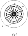
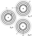
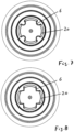
- Draufsichten auf den Gehäuseboden der Kapsel ohne Innenplatte mit unterschiedlich geformten Schwachstellen.
- Die erfindungsgemäße Portionskapsel 1 ist dazu vorgesehen, in einer Getränkevorrichtung insbesondere in einer Kaffee- oder Teemaschine eingesetzt zu werden, um ein Getränk insbesondere Kaffee oder Tee aus einem Substrat, Granulat oder Pulver zu schaffen, das sich innerhalb der Kapsel befindet. Die Portionskapsel 1 ist eine topfförmige Kapsel 1, in der sich das Substrat, Granulat oder Pulver befindet. Die Kapsel ist zu einer Seite, in diesem Fall dem Einlassende 4 geöffnet, wobei diese Öffnung 5 durch einen Film oder eine Folie geschlossen ist, die auf dem flanschförmigen Rand 5a der Kapsel aufgeheftet ist, so dass die Öffnung 5 sicher verschlossen ist. Hierdurch ist sichergestellt, dass nach einem Durchstechen des Films/der Folie durch ein Rohr insbesondere eine Lanze, die durch das Rohr/Lanze eindringende Flüssigkeit insbesondere heißes oder kaltes Wasser in die Kapsel 1 gelangt.
- Die Portionskapsel 1 ist von einem topfförmigen Gehäuse aus Kunststoff gebildet mit einem unteren Gehäuseboden 3 auf dem ein ringförmiger zylindrischer Vorsprung (Ringvorsprung 11) angeformt in das Kapselinnere hinein vorsteht, dessen Achse gleich der Kapselachse 12 ist. Der Innendurchmesser des Ringvorsprungs ist gleich 1/3 bis ¾ des Durchmessers der Eingangsöffnung 5. Die Höhe bzw. Breite des Ringvorsprungs beträgt 2 bis 6 mm.
- Die Kapsel 1 weist in ihrem Boden 3 innerhalb des Ringvorsprungs 11 mindestens eine insbesondere kreisbogenförmige Schwachstelle 6 im Kunststoff der Kapsel 1 auf, die bei in der Kapsel anliegendem Flüssigkeitsdruck sich öffnet, bricht oder reißt, um Flüssigkeit aus dem Innenraum der Kapsel zum Getränkeauslass 7 hindurchzulassen. Vorzugsweise besteht die Schwachstelle 6 aus einer Aufreißlinie, so dass beim Aufreißen ein Teil des Gehäusebodens 10 nach unten durchbricht. Diese Schwachstelle 6 kann auch eine Aufreißkerbe, Aufreißnaht oder eine andere Art der Schwächung sein.
- In der in der
Fig. 3 dargestellten Ausführung weist der Boden 3 der Kapsel 1 vier insbesondere kreisbogenförmige Schwachstellen 6 auf, die gleichmäßig über einen Kreis verteilt sind, der nahe des Bodenrandes zentrisch und damit koaxial zur Mittelachse 12 der Portionskapsel liegt. Im Bereich der Schwachstellen weist der Kunststoff des Bodens eine solch geringe Dicke auf, dass dort der Kunststoff durchbricht/aufreißt durch den im Inneren der Innenkapsel entstehenden Flüssigkeitsdruck. - Um sicher zu stellen, dass der Inhalt der Kapsel 1 während der Lagerung der Kapsel in seiner Qualität nicht abnimmt, besteht in einer Ausführung die Wand der Kapsel 1 aus einer Barriereschicht oder Sperrschicht aus Ethylen-Vinylalkohol-Copolymer (EVOH) oder aus Polyolefin mit eingebetteter Zwischenschicht aus Ethylen-Vinylalkohol-Copolymer (EVOH) oder aus einem biologisch abbaubarem Polylactid (PLA) mit eingebetteter Zwischenschicht aus EVOH oder Polyvinylalkohol (PVOH).
- Die Kapsel 1 wird im Kunststoffspritzguss hergestellt. Hierbei ist es wichtig, dass beim Einspritzen des Kunststoffes in die Mitte des den Gehäuseboden 3 bildenden Hohlraums des Spritzgusswerkzeugs die Kunststoffschmelze gleichmäßig von der Mitte zum kreisförmigen Rand des Bodens fließt. Hierbei sind aber die Schwachstellen 6 als Dünnstellen im Weg, die jeweils einen Fließwiderstand erzeugen und den Schmelzfluss behindern. Um dennoch einen gleichmäßigen Fluss bis zum Außenrand des Bodens 3 und auch zu der Seitenwand der Kapsel 1 zu erhalten, sind zwischen den Schwachstellen 6 kreisbogenförmige Dünnstellen 20 angeordnet, die auf dem Kreis liegen, auf dem sich auch die Schwachstellen 6 befinden und dessen Mittelpunkt der Mittelpunkt des Bodens 3 der Kapsel 1 ist, der gleichzeitig auch die Angussstelle der Kapsel ist.
- Im Bereich der Dünnstellen 20 weist das Material eine größere Dicke auf als im Bereich der Schwachstellen 6, so dass sichergestellt ist, dass durch den Flüssigkeitsdruck innerhalb der Portionskapsel nur die Schwachstellen 6 und nicht die Dünnstellen 20 aufreißen bzw. aufbrechen.
- Damit beim Einspritzen des Kunststoffs der Fließwiderstand über den gesamten Umfang des Kreises und damit bei den Dünnstellen 20 gleich groß ist wie bei den Schwachstellen 6 weisen die Dünnstellen 20 eine größere radiale Breite B1 auf als die radiale Breite B2 der Schwachstellen 6.
- Im Ausführungsbeispiel sind vier kreisbogenförmige Schwachstellen 6 und vier kreisbogenförmige Dünnstellen 20 dazwischen angeordnet, die alle zusammen einen ununterbrochenen Kreis bilden. Stattdessen können aber auch drei, fünf oder sechs Schwachstellen und Dünnstellen jeweils einen Kreis bilden.
- Der Boden 3 der Kapsel, die Schwachstellen 6 und die Dünnstellen 20 weisen vorzugsweise folgende Abmessungen auf:
Dicke (mm) Breite (mm) Kreisbogenlänge (Grad) Boden 3 der Kapsel 0,5 - 1,0 vorzugsweise 0,7 - - Schwachstellen 6 0,10 - 0,20 vorzugsweise 0,15 0,1 - 0,3 vorzugsweise 0,2 3-50° vorzugsweise 10° bis 40° Dünnstellen 20 0,20 - 0,30 vorzugsweise 0,25 0,7 bis 2,0 vorzugsweise 1,3 75 - 85° vorzugsweise 80° - In dem Ausführungsbeispiel nach
Fig. 1 liegt innerhalb des Ringvorsprungs 11 waagerecht eine Innenplatte 8 parallel zum Boden 3. Diese Innenplatte 8 füllt den Innenraum des Ringvorsprungs vollkommen aus, so dass sie formschlüssig im Innenraum des Ringvorsprungs 11 einliegt und dort den Boden 3 abdeckt. Der zylindrische Außenrand der Innenplatte 8 liegt hierbei dicht am Innenrand des Ringvorsprungs 11 an. Die Dicke D der Innenplatte 8 beträgt 1 bis 10 mm. - Im zylindrischen Außenrand 9 der Innenplatte 8 befinden sich zahlreiche Kerben und/oder Nuten 35, die ein Durchströmen des aus dem Innenraum der Innenkapsel kommenden Wassers begrenzt zu lassen, so dass das unter Druck stehende Wasser den Außenrand 9 umströmt, um zu den Schwachstellen 6 im Boden 3 zu gelangen.
- Hierdurch wird eine Fließverzögerung erreicht und zudem verhindert, dass das Wasser aus der Portionskapsel heraus nachtropft.
- Ein über der Innenplatte 8 liegendes Sieb 21 insbesondere in Form einer perforierten Folie hält Substrat-Partikel zurück.
- Auf der Unterseite des Gehäusebodens 3 steht ein angeformter zweiter Ringvorsprung 17 nach unten vor, dessen Durchmesser gleich oder geringer ist als der Durchmesser des ersten Ringvorsprungs 11, wobei der Durchmesser des zweiten Ringvorsprungs 17 so groß gewählt ist, dass die Schwachstellen 6 innerhalb des zweiten Ringvorsprungs 17 liegen. Die Achse des zweiten Ringvorsprungs liegt auf der Kapselachse 12.
- Der zweite Ringvorsprung 17 ist außenseitig von einem schalenförmigen Kunststoffteil 23 umgriffen, der den unteren Auslaufraum 22 der Portionskapsel 1 bildet und einen unteren mittigen Getränkeauslauf 7 besitzt.
- Die in
Fig. 2 dargestellte zweite Ausführungsform unterscheidet sich von der ersten im Wesentlichen dadurch, dass die Innenplatte 8 einen größeren Außendurchmesser aufweist als der Außendurchmesser des ersten Ringvorsprungs 11, so dass die Innenplatte 8 rundum über den Ringvorsprung 11 radial hinausragt und hierzu einen ringförmigen Außenrand 8a bildet, der den Ringraum 14 insbesondere formschlüssig ausfüllt. Hier liegt die Unterseite des Außenrandes 8a dicht auf dem Gehäuseboden 3 abdichtend auf und die Innenplatte 8 besitzt an ihrer Unterseite eine nach unten offene Ringnut 8b, in die der Ringvorsprung 11 hineinragt. - Der ringförmige Außenrand 8a weist senkrechte kanalförmige3 Sieböffnungen 16 auf, die die Oberseite des Außenrandes 8a mit dessen Unterseite verbinden, so dass der Außenrand wie ein Sieb wirkt. Die Unterseite des Außenrandes 8a besitzt radiale Durchflusskanäle 15, in die Sieböffnungen 16 münden. Bei Aufbau des Flüssigkeitsdruckes im Innenraum der Portionskapsel 1 strömt die Flüssigkeit vom Innenraum in die Sieböffnungen 16 und in die Kanäle 15, dann in die Ringnut 8b, um den Ringvorsprung 11 zu überströmen und unterhalb der Innenplatte 8 zu den Schwachstellen 6 zu gelangen, um diese zu öffnen, so dass die Flüssigkeit in den Auslaufraum 22 und zum Getränkeauslass 7 gelangt.
- Die Schwachstelle ist in
Fig. 3 als Teil eines Kreisbogens geformt. In denFig. 4 bis 8 haben die Schwachstellen 6 dagegen die Form eines Dreiecks, einer Welle, einer oder mehrerer Zacken, eines Ovals, eines U oder eines V. - Innerhalb des Innenraums der Innenkapsel ist eine obere Lochplatte (nicht dargestellt) parallel zum Boden 3 und parallel zur oberen Abdeckfolie befestigt, die den Innenraum in einen Oberraum und einen Unterraum trennt. In dem Oberraum gelangt das Wasser durch eine Lanze und über die Löcher in der Lochplatte fließt das Wasser in den das Getränke-Substrat speichernden Unterraum. Die Löcher sind in der Lochplatte in regelmäßigen Abständen angeordnet, so dass das Wasser im Substrat gleichmäßig verteilt wird.
Claims (13)
- Portionskapsel (1) zum Herstellen eines Getränkes wie Kaffee oder Tee in einer Getränkevorrichtung, die an ihrem Auslassende (2) durch einen Gehäuseboden (3) verschlossen ist und an dem gegenüberliegenden Einlassende (4) eine Öffnung (5) bildet, die durch eine Folie verschlossen ist, die von einer Einrichtung perforierbar ist, um Wasser in den Kapselinnenraum zu pressen, der ein Getränke-Substrat, -Granulat und/oder -Pulver enthält, weiterhin charakterisiert durch:- dass die Kapsel (1) in ihrem Gehäuseboden (3) Schwachstellen (6) aufweist, die bei im Kapselinnenraum anliegendem Flüssigkeitsdruck sich öffnen, brechen oder reißen, um Flüssigkeit aus dem Innenraum der Kapsel (1) zum Getränkeauslass (7) durchzulassen,- dass der Gehäuseboden (3) von einer scheibenförmigen Innenplatte (8) bedeckt ist, deren Außenrand (9) Flüssigkeitsdurchlässe (10) aufweist, durch die bei anliegendem Flüssigkeitsdruck die Flüssigkeit aus dem Innenraum der Kapsel (1) zu den Schwachstellen (6) des Bodens (3) strömt, dadurch gekennzeichnet:- dass auf dem Gehäuseboden (3) ein in den Kapselinnenraum hineinragender Ringvorsprung (11) vorsteht, der koaxial zur Kapselachse (12) angeordnet ist, und- dass die Innenplatte (8) im Innenraum (13) des Ringvorsprungs (11) formschlüssig einliegt und hierbei den Innenraum ausfüllt.
- Portionskapsel nach Anspruch 1, dadurch gekennzeichnet, dass die Innenplatte (8) im Innenraum (13) des Ringvorsprungs (11) einliegt, und hierbei den Ringvorsprung seitlich überragt, um mit seinem Außenrand (8a) im Ringraum (14) einzuliegen, der den Ringvorsprung umgibt.
- Portionskapsel nach Anspruch 2, dadurch gekennzeichnet, dass der Außenrand (8a) der Innenplatte (8) auf dem Gehäuseboden (3) aufliegt.
- Portionskapsel nach Anspruch 2 oder 3, dadurch gekennzeichnet, dass der Außenrand (8a) der Innenplatte (8) im Ringraum (14) formschlüssig einliegt.
- Portionskapsel nach einem der Ansprüche 2 bis 4, dadurch gekennzeichnet, dass der Außenrand (8a) der Innenplatte (8) siebförmig durchlöchert ist.
- Portionskapsel nach einem der Ansprüche 2 bis 5, dadurch gekennzeichnet, dass der Außenrand (8a) der Innenplatte (8) auf der dem Gehäuseboden (3) zugewandten Unterseite Durchflusskanäle (15) bildet, die die Flüssigkeit von den Sieböffnungen (16) über den Ringvorsprung (11) hinweg zu den Schwachstellen (6) führt.
- Portionskapsel nach einem der vorherigen Ansprüche, dadurch gekennzeichnet, dass der Boden (3) der Kapsel (1) als Schwachstelle (6) nahe seinem Außenrand mindestens eine Brechstelle oder mindestens eine Aufreißlinie aufweist.
- Portionskapsel nach Anspruch 7, dadurch gekennzeichnet, dass die Schwachstellen (6) auf einem Kreis liegen, der zentrisch zur Mitte des Bodens (3) der Kapsel (1) ist.
- Portionskapsel nach einem der vorherigen Ansprüche, dadurch gekennzeichnet, dass auf der Unterseite des Gehäusebodens (3) ein zweiter Ringvorsprung (17) nach unten koaxial zur Kappenachse vorsteht.
- Portionskapsel nach Anspruch 9, dadurch gekennzeichnet, dass am zweiten Ringvorsprung (17) ein Auslaufraum (22) formschlüssig insbesondere angeclipst befestigt ist.
- Portionskapsel nach einem der vorherigen Ansprüche dadurch gekennzeichnet, dass der Boden (3) der Kapsel (1) zum gleichmäßigen Führen der Kunststoffschmelze beim Kunststoffspritzguss kreisbogenförmige Dünnstellen (20) aufweist,- die auf dem zentrischen Kreis der Schwachstellen (6) liegen,- die die Zwischenräume zwischen den Schwachstellen (6) ausfüllen und- die eine Materialdicke aufweisen, die so viel größer ist als die Materialdicke der Schwachstellen (6), dass sie im Gegensatz zu den Schwachstellen (6) durch den Flüssigkeitsdruck nicht aufreißen oder aufbrechen.
- Portionskapsel nach Anspruch 11, dadurch gekennzeichnet, dass zwei bis acht insbesondere vier Schwachstellen (6) in gleichen Abständen auf dem Kreis angeordnet sind und die Kreiszwischenräume zwischen den Schwachstellen durch die kreisbogenförmigen Dünnstellen (20) gleicher Anzahl ausgefüllt sind.
- Portionskapsel nach einem der vorherigen Ansprüche, dadurch gekennzeichnet, dass die Schwachstellen (6) die Form eines Dreiecks, einer Welle, einer oder mehrerer Zacken, eines Ovals, eines U oder eines V besitzt.
Applications Claiming Priority (2)
| Application Number | Priority Date | Filing Date | Title |
|---|---|---|---|
| DE102017005363.4A DE102017005363A1 (de) | 2017-06-07 | 2017-06-07 | Portionskapsel zum Herstellen eines Getränkes |
| PCT/EP2018/000112 WO2018224177A1 (de) | 2017-06-07 | 2018-03-23 | Portionskapsel zum herstellen eines getränkes |
Publications (3)
| Publication Number | Publication Date |
|---|---|
| EP3571140A1 EP3571140A1 (de) | 2019-11-27 |
| EP3571140B1 true EP3571140B1 (de) | 2024-07-17 |
| EP3571140C0 EP3571140C0 (de) | 2024-07-17 |
Family
ID=61911506
Family Applications (1)
| Application Number | Title | Priority Date | Filing Date |
|---|---|---|---|
| EP18716094.0A Active EP3571140B1 (de) | 2017-06-07 | 2018-03-23 | Portionskapsel zum herstellen eines getränkes |
Country Status (9)
| Country | Link |
|---|---|
| EP (1) | EP3571140B1 (de) |
| CN (1) | CN110546082A (de) |
| CO (1) | CO2019011468A2 (de) |
| DE (1) | DE102017005363A1 (de) |
| ES (1) | ES2986841T3 (de) |
| MX (1) | MX2019012302A (de) |
| PL (1) | PL3571140T3 (de) |
| RU (1) | RU2749230C2 (de) |
| WO (1) | WO2018224177A1 (de) |
Family Cites Families (13)
| Publication number | Priority date | Publication date | Assignee | Title |
|---|---|---|---|---|
| PT1555218E (pt) * | 2004-02-11 | 2006-11-30 | I T A Ca S R L | Cartucho para café |
| EP1908706B1 (de) * | 2006-06-06 | 2009-12-23 | Nestec S.A. | Kapsel mit reduziertem Nachtropfen |
| ITMI20061503A1 (it) * | 2006-07-28 | 2008-01-29 | Illycaffe Spa | Perfezionamenti di capsule contenenti una sostanza in polvere da cui estrarre una bevanda,preferibilmente caffe' espresso |
| ITMI20070740A1 (it) * | 2007-04-12 | 2008-10-13 | Rossi Corp S R L | Capsula monouso di contenimento di un essenza aromatica per la produzione di un infuso |
| EP1982933B1 (de) * | 2007-04-18 | 2010-08-11 | ILLYCAFFE' S.p.A. | Starrer Filter für zum Brühen von Getränken geeignete Kapseln, insbesondere Espressokaffee |
| DE102009041633A1 (de) * | 2009-09-17 | 2011-06-01 | Krüger Gmbh & Co. Kg | Portionskapsel und Verwendung einer Portionskapsel |
| RU2607759C2 (ru) * | 2011-03-28 | 2017-01-10 | Конинклейке Дауве Эгбертс Б.В. | Картридж напитка и фильтрующий элемент |
| CH709296B1 (de) * | 2014-02-21 | 2022-08-15 | Delica Ag | Kapsel mit einem vorzugsweise rotationssymmetrisch ausgebildeten Kapselkörper. |
| BR112017001838A2 (pt) * | 2014-07-31 | 2017-11-21 | Caffitaly System Spa | ?filtro para cápsulas para fazer café expresso e cápsula para fazer café expresso? |
| KR20170107966A (ko) * | 2014-11-19 | 2017-09-26 | 코스웰 에스.피.에이. | 음료 분배용 캡슐 및 그 제조방법 |
| WO2016085361A1 (en) * | 2014-11-24 | 2016-06-02 | Teixeira E Silva Cardoso Paulo Alexandre | Single dose capsole, system and process for preparing edible products using said single dose capsule |
| DE102015011787A1 (de) * | 2015-09-16 | 2017-03-16 | Georg Menshen Gmbh & Co. Kg | Portionskapsel zum Herstellen eines Getränkes |
| ITUB20155389A1 (it) * | 2015-11-09 | 2017-05-09 | Sarong Spa | Capsula per bevande |
-
2017
- 2017-06-07 DE DE102017005363.4A patent/DE102017005363A1/de not_active Withdrawn
-
2018
- 2018-03-23 EP EP18716094.0A patent/EP3571140B1/de active Active
- 2018-03-23 RU RU2019130380A patent/RU2749230C2/ru active
- 2018-03-23 PL PL18716094.0T patent/PL3571140T3/pl unknown
- 2018-03-23 WO PCT/EP2018/000112 patent/WO2018224177A1/de not_active Ceased
- 2018-03-23 CN CN201880027398.4A patent/CN110546082A/zh active Pending
- 2018-03-23 MX MX2019012302A patent/MX2019012302A/es unknown
- 2018-03-23 ES ES18716094T patent/ES2986841T3/es active Active
-
2019
- 2019-10-17 CO CONC2019/0011468A patent/CO2019011468A2/es unknown
Also Published As
| Publication number | Publication date |
|---|---|
| PL3571140T3 (pl) | 2024-11-25 |
| DE102017005363A1 (de) | 2018-12-13 |
| EP3571140A1 (de) | 2019-11-27 |
| CO2019011468A2 (es) | 2020-02-28 |
| RU2019130380A3 (de) | 2021-03-26 |
| MX2019012302A (es) | 2020-01-13 |
| ES2986841T3 (es) | 2024-11-12 |
| RU2749230C2 (ru) | 2021-06-07 |
| EP3571140C0 (de) | 2024-07-17 |
| BR112019019968A2 (pt) | 2020-04-28 |
| WO2018224177A1 (de) | 2018-12-13 |
| CN110546082A (zh) | 2019-12-06 |
| RU2019130380A (ru) | 2021-03-26 |
Similar Documents
| Publication | Publication Date | Title |
|---|---|---|
| EP2238050B1 (de) | Labyrinth-kapsel für getränkepulver | |
| DE69801081T2 (de) | Baueinheit zum Einsatz in einem Kaffeebrühgerät, sowie deren Filterbehälter und Filterbeutel dafür | |
| EP3107835B1 (de) | Kapsel mit einem vorzugsweise rotationssymmetrisch ausgebildeten kapselkörper | |
| DE3049956C2 (de) | ||
| EP2794462B1 (de) | Füllelement sowie füllsystem | |
| DE1529389A1 (de) | Spritzschutzvorrichtung fuer Trinkgefaesse | |
| EP3222557A1 (de) | Kapselsystem | |
| EP3052408A1 (de) | Kapsel und system zur zubereitung eines flüssigen lebensmittels, sowie kapselkörper | |
| DE2931283C2 (de) | Einwegventil für Flaschen | |
| EP2957524B1 (de) | Kapsel für getränkzubereitung | |
| WO2009046551A1 (de) | Kunststoffverschluss | |
| CH708662A1 (de) | Kapsel und System zur Zubereitung eines flüssigen Lebensmittels. | |
| AT402556B (de) | Flüssiggas-feuerzeug | |
| EP3241781B1 (de) | Tube mit drosseleinsatz | |
| EP3144250B1 (de) | Portionskapsel zum herstellen eines getränkes | |
| WO2009135591A1 (de) | Füllelement sowie füllmaschine mit derartigen füllelementen | |
| EP2697151B1 (de) | Füllelement | |
| DE102018002102A1 (de) | Portionskapsel mit Schwachstellen und Dünnstellen im Kapselboden | |
| DE102017005363A1 (de) | Portionskapsel zum Herstellen eines Getränkes | |
| DE2141071C3 (de) | Tropf- oder Gießeinsatz | |
| EP3272672A1 (de) | Kapsel | |
| EP3272675A1 (de) | Kapsel zur zubereitung eines flüssigen lebensmittels | |
| DE3832045C1 (en) | Drinks filling (bottling) machine | |
| DE10217758A1 (de) | Rückstromsperre für Spritzgießmaschine | |
| DE102016010895A1 (de) | Portionskapsel zum Herstellen eines Getränkes |
Legal Events
| Date | Code | Title | Description |
|---|---|---|---|
| STAA | Information on the status of an ep patent application or granted ep patent |
Free format text: STATUS: UNKNOWN |
|
| STAA | Information on the status of an ep patent application or granted ep patent |
Free format text: STATUS: THE INTERNATIONAL PUBLICATION HAS BEEN MADE |
|
| PUAI | Public reference made under article 153(3) epc to a published international application that has entered the european phase |
Free format text: ORIGINAL CODE: 0009012 |
|
| STAA | Information on the status of an ep patent application or granted ep patent |
Free format text: STATUS: REQUEST FOR EXAMINATION WAS MADE |
|
| 17P | Request for examination filed |
Effective date: 20190821 |
|
| AK | Designated contracting states |
Kind code of ref document: A1 Designated state(s): AL AT BE BG CH CY CZ DE DK EE ES FI FR GB GR HR HU IE IS IT LI LT LU LV MC MK MT NL NO PL PT RO RS SE SI SK SM TR |
|
| AX | Request for extension of the european patent |
Extension state: BA ME |
|
| DAV | Request for validation of the european patent (deleted) | ||
| DAX | Request for extension of the european patent (deleted) | ||
| STAA | Information on the status of an ep patent application or granted ep patent |
Free format text: STATUS: EXAMINATION IS IN PROGRESS |
|
| 17Q | First examination report despatched |
Effective date: 20220525 |
|
| GRAP | Despatch of communication of intention to grant a patent |
Free format text: ORIGINAL CODE: EPIDOSNIGR1 |
|
| STAA | Information on the status of an ep patent application or granted ep patent |
Free format text: STATUS: GRANT OF PATENT IS INTENDED |
|
| INTG | Intention to grant announced |
Effective date: 20240307 |
|
| GRAS | Grant fee paid |
Free format text: ORIGINAL CODE: EPIDOSNIGR3 |
|
| GRAA | (expected) grant |
Free format text: ORIGINAL CODE: 0009210 |
|
| STAA | Information on the status of an ep patent application or granted ep patent |
Free format text: STATUS: THE PATENT HAS BEEN GRANTED |
|
| AK | Designated contracting states |
Kind code of ref document: B1 Designated state(s): AL AT BE BG CH CY CZ DE DK EE ES FI FR GB GR HR HU IE IS IT LI LT LU LV MC MK MT NL NO PL PT RO RS SE SI SK SM TR |
|
| REG | Reference to a national code |
Ref country code: CH Ref legal event code: EP |
|
| REG | Reference to a national code |
Ref country code: DE Ref legal event code: R096 Ref document number: 502018014865 Country of ref document: DE |
|
| REG | Reference to a national code |
Ref country code: IE Ref legal event code: FG4D Free format text: LANGUAGE OF EP DOCUMENT: GERMAN |
|
| U01 | Request for unitary effect filed |
Effective date: 20240801 |
|
| U07 | Unitary effect registered |
Designated state(s): AT BE BG DE DK EE FI FR IT LT LU LV MT NL PT SE SI Effective date: 20240813 |
|
| REG | Reference to a national code |
Ref country code: ES Ref legal event code: FG2A Ref document number: 2986841 Country of ref document: ES Kind code of ref document: T3 Effective date: 20241112 |
|
| PG25 | Lapsed in a contracting state [announced via postgrant information from national office to epo] |
Ref country code: NO Free format text: LAPSE BECAUSE OF FAILURE TO SUBMIT A TRANSLATION OF THE DESCRIPTION OR TO PAY THE FEE WITHIN THE PRESCRIBED TIME-LIMIT Effective date: 20241017 |
|
| PG25 | Lapsed in a contracting state [announced via postgrant information from national office to epo] |
Ref country code: GR Free format text: LAPSE BECAUSE OF FAILURE TO SUBMIT A TRANSLATION OF THE DESCRIPTION OR TO PAY THE FEE WITHIN THE PRESCRIBED TIME-LIMIT Effective date: 20241018 |
|
| PG25 | Lapsed in a contracting state [announced via postgrant information from national office to epo] |
Ref country code: IS Free format text: LAPSE BECAUSE OF FAILURE TO SUBMIT A TRANSLATION OF THE DESCRIPTION OR TO PAY THE FEE WITHIN THE PRESCRIBED TIME-LIMIT Effective date: 20241117 |
|
| PG25 | Lapsed in a contracting state [announced via postgrant information from national office to epo] |
Ref country code: HR Free format text: LAPSE BECAUSE OF FAILURE TO SUBMIT A TRANSLATION OF THE DESCRIPTION OR TO PAY THE FEE WITHIN THE PRESCRIBED TIME-LIMIT Effective date: 20240717 |
|
| PG25 | Lapsed in a contracting state [announced via postgrant information from national office to epo] |
Ref country code: RS Free format text: LAPSE BECAUSE OF FAILURE TO SUBMIT A TRANSLATION OF THE DESCRIPTION OR TO PAY THE FEE WITHIN THE PRESCRIBED TIME-LIMIT Effective date: 20241017 |
|
| U1N | Appointed representative for the unitary patent procedure changed after the registration of the unitary effect |
Representative=s name: COHAUSZ HANNIG BORKOWSKI WISSGOTT; DE |
|
| PG25 | Lapsed in a contracting state [announced via postgrant information from national office to epo] |
Ref country code: RS Free format text: LAPSE BECAUSE OF FAILURE TO SUBMIT A TRANSLATION OF THE DESCRIPTION OR TO PAY THE FEE WITHIN THE PRESCRIBED TIME-LIMIT Effective date: 20241017 Ref country code: NO Free format text: LAPSE BECAUSE OF FAILURE TO SUBMIT A TRANSLATION OF THE DESCRIPTION OR TO PAY THE FEE WITHIN THE PRESCRIBED TIME-LIMIT Effective date: 20241017 Ref country code: IS Free format text: LAPSE BECAUSE OF FAILURE TO SUBMIT A TRANSLATION OF THE DESCRIPTION OR TO PAY THE FEE WITHIN THE PRESCRIBED TIME-LIMIT Effective date: 20241117 Ref country code: HR Free format text: LAPSE BECAUSE OF FAILURE TO SUBMIT A TRANSLATION OF THE DESCRIPTION OR TO PAY THE FEE WITHIN THE PRESCRIBED TIME-LIMIT Effective date: 20240717 Ref country code: GR Free format text: LAPSE BECAUSE OF FAILURE TO SUBMIT A TRANSLATION OF THE DESCRIPTION OR TO PAY THE FEE WITHIN THE PRESCRIBED TIME-LIMIT Effective date: 20241018 |
|
| PG25 | Lapsed in a contracting state [announced via postgrant information from national office to epo] |
Ref country code: SM Free format text: LAPSE BECAUSE OF FAILURE TO SUBMIT A TRANSLATION OF THE DESCRIPTION OR TO PAY THE FEE WITHIN THE PRESCRIBED TIME-LIMIT Effective date: 20240717 |
|
| PG25 | Lapsed in a contracting state [announced via postgrant information from national office to epo] |
Ref country code: CZ Free format text: LAPSE BECAUSE OF FAILURE TO SUBMIT A TRANSLATION OF THE DESCRIPTION OR TO PAY THE FEE WITHIN THE PRESCRIBED TIME-LIMIT Effective date: 20240717 |
|
| PG25 | Lapsed in a contracting state [announced via postgrant information from national office to epo] |
Ref country code: SK Free format text: LAPSE BECAUSE OF FAILURE TO SUBMIT A TRANSLATION OF THE DESCRIPTION OR TO PAY THE FEE WITHIN THE PRESCRIBED TIME-LIMIT Effective date: 20240717 |
|
| U20 | Renewal fee for the european patent with unitary effect paid |
Year of fee payment: 8 Effective date: 20250325 |
|
| PLBE | No opposition filed within time limit |
Free format text: ORIGINAL CODE: 0009261 |
|
| STAA | Information on the status of an ep patent application or granted ep patent |
Free format text: STATUS: NO OPPOSITION FILED WITHIN TIME LIMIT |
|
| 26N | No opposition filed |
Effective date: 20250422 |
|
| PGFP | Annual fee paid to national office [announced via postgrant information from national office to epo] |
Ref country code: ES Payment date: 20250416 Year of fee payment: 8 |
|
| PG25 | Lapsed in a contracting state [announced via postgrant information from national office to epo] |
Ref country code: MC Free format text: LAPSE BECAUSE OF FAILURE TO SUBMIT A TRANSLATION OF THE DESCRIPTION OR TO PAY THE FEE WITHIN THE PRESCRIBED TIME-LIMIT Effective date: 20240717 |
|
| REG | Reference to a national code |
Ref country code: CH Ref legal event code: H13 Free format text: ST27 STATUS EVENT CODE: U-0-0-H10-H13 (AS PROVIDED BY THE NATIONAL OFFICE) Effective date: 20251023 |
|
| GBPC | Gb: european patent ceased through non-payment of renewal fee |
Effective date: 20250323 |
|
| PG25 | Lapsed in a contracting state [announced via postgrant information from national office to epo] |
Ref country code: GB Free format text: LAPSE BECAUSE OF NON-PAYMENT OF DUE FEES Effective date: 20250323 |
|
| PG25 | Lapsed in a contracting state [announced via postgrant information from national office to epo] |
Ref country code: CH Free format text: LAPSE BECAUSE OF NON-PAYMENT OF DUE FEES Effective date: 20250331 |
|
| PG25 | Lapsed in a contracting state [announced via postgrant information from national office to epo] |
Ref country code: IE Free format text: LAPSE BECAUSE OF NON-PAYMENT OF DUE FEES Effective date: 20250323 |
|
| PG25 | Lapsed in a contracting state [announced via postgrant information from national office to epo] |
Ref country code: RO Free format text: LAPSE BECAUSE OF FAILURE TO SUBMIT A TRANSLATION OF THE DESCRIPTION OR TO PAY THE FEE WITHIN THE PRESCRIBED TIME-LIMIT Effective date: 20240717 |
|
| PGFP | Annual fee paid to national office [announced via postgrant information from national office to epo] |
Ref country code: PL Payment date: 20260311 Year of fee payment: 9 |
|
| U20 | Renewal fee for the european patent with unitary effect paid |
Year of fee payment: 9 Effective date: 20260327 |