EP3571112B1 - Pillar reinforcement - Google Patents
Pillar reinforcement Download PDFInfo
- Publication number
- EP3571112B1 EP3571112B1 EP18703439.2A EP18703439A EP3571112B1 EP 3571112 B1 EP3571112 B1 EP 3571112B1 EP 18703439 A EP18703439 A EP 18703439A EP 3571112 B1 EP3571112 B1 EP 3571112B1
- Authority
- EP
- European Patent Office
- Prior art keywords
- structural reinforcement
- longitudinal axis
- upper portion
- expandable
- ribs
- Prior art date
- Legal status (The legal status is an assumption and is not a legal conclusion. Google has not performed a legal analysis and makes no representation as to the accuracy of the status listed.)
- Active
Links
- 230000002787 reinforcement Effects 0.000 title claims description 47
- 239000000463 material Substances 0.000 claims description 57
- 239000000853 adhesive Substances 0.000 claims description 13
- 230000001070 adhesive effect Effects 0.000 claims description 13
- 230000004913 activation Effects 0.000 claims description 2
- 238000000034 method Methods 0.000 description 4
- 239000004593 Epoxy Substances 0.000 description 3
- 238000000465 moulding Methods 0.000 description 2
- 239000004814 polyurethane Substances 0.000 description 2
- 229920002635 polyurethane Polymers 0.000 description 2
- 230000003014 reinforcing effect Effects 0.000 description 2
- 229920001169 thermoplastic Polymers 0.000 description 2
- 239000004416 thermosoftening plastic Substances 0.000 description 2
- 239000004952 Polyamide Substances 0.000 description 1
- 230000009286 beneficial effect Effects 0.000 description 1
- 239000011248 coating agent Substances 0.000 description 1
- 238000000576 coating method Methods 0.000 description 1
- 239000000835 fiber Substances 0.000 description 1
- 239000003365 glass fiber Substances 0.000 description 1
- 238000002347 injection Methods 0.000 description 1
- 239000007924 injection Substances 0.000 description 1
- 238000001746 injection moulding Methods 0.000 description 1
- 238000004519 manufacturing process Methods 0.000 description 1
- 238000012986 modification Methods 0.000 description 1
- 230000004048 modification Effects 0.000 description 1
- 238000010422 painting Methods 0.000 description 1
- 229920002647 polyamide Polymers 0.000 description 1
- 239000012779 reinforcing material Substances 0.000 description 1
- 239000012812 sealant material Substances 0.000 description 1
- 239000012815 thermoplastic material Substances 0.000 description 1
- 229920001187 thermosetting polymer Polymers 0.000 description 1
Images


Classifications
-
- B—PERFORMING OPERATIONS; TRANSPORTING
- B62—LAND VEHICLES FOR TRAVELLING OTHERWISE THAN ON RAILS
- B62D—MOTOR VEHICLES; TRAILERS
- B62D29/00—Superstructures, understructures, or sub-units thereof, characterised by the material thereof
- B62D29/001—Superstructures, understructures, or sub-units thereof, characterised by the material thereof characterised by combining metal and synthetic material
- B62D29/002—Superstructures, understructures, or sub-units thereof, characterised by the material thereof characterised by combining metal and synthetic material a foamable synthetic material or metal being added in situ
-
- B—PERFORMING OPERATIONS; TRANSPORTING
- B62—LAND VEHICLES FOR TRAVELLING OTHERWISE THAN ON RAILS
- B62D—MOTOR VEHICLES; TRAILERS
- B62D25/00—Superstructure or monocoque structure sub-units; Parts or details thereof not otherwise provided for
-
- B—PERFORMING OPERATIONS; TRANSPORTING
- B62—LAND VEHICLES FOR TRAVELLING OTHERWISE THAN ON RAILS
- B62D—MOTOR VEHICLES; TRAILERS
- B62D27/00—Connections between superstructure or understructure sub-units
- B62D27/02—Connections between superstructure or understructure sub-units rigid
-
- B—PERFORMING OPERATIONS; TRANSPORTING
- B62—LAND VEHICLES FOR TRAVELLING OTHERWISE THAN ON RAILS
- B62D—MOTOR VEHICLES; TRAILERS
- B62D29/00—Superstructures, understructures, or sub-units thereof, characterised by the material thereof
- B62D29/001—Superstructures, understructures, or sub-units thereof, characterised by the material thereof characterised by combining metal and synthetic material
- B62D29/004—Superstructures, understructures, or sub-units thereof, characterised by the material thereof characterised by combining metal and synthetic material the metal being over-moulded by the synthetic material, e.g. in a mould
-
- B—PERFORMING OPERATIONS; TRANSPORTING
- B62—LAND VEHICLES FOR TRAVELLING OTHERWISE THAN ON RAILS
- B62D—MOTOR VEHICLES; TRAILERS
- B62D29/00—Superstructures, understructures, or sub-units thereof, characterised by the material thereof
- B62D29/04—Superstructures, understructures, or sub-units thereof, characterised by the material thereof predominantly of synthetic material
Definitions
- the present teachings relate generally to reinforcement of structures, and more particularly to reinforcement of vehicle structures using structural reinforcements with associated activatable (e.g., expandable) materials.
- activatable e.g., expandable
- vehicle pillars A pillar, B, pillar C, pillar
- vehicle pillars often experience significant stress during crash, especially at locations where the pillars are joined with the vehicle roof. It would thus be beneficial to provide additional support at such locations.
- the present teachings pertain to a structural reinforcement comprising a rigid polymeric structure having a longitudinal axis and including a lower portion and an upper portion, each of the lower and upper portions including a top surface and bottom surface, and an expandable adhesive material located onto a portion of each of the top and bottom surface of each of the upper and lower portions.
- the rigid polymeric structure may include a plurality of ribs and the top edge of one or more of the ribs may be co-planar with the expandable adhesive material prior to activation of the expandable adhesive material.
- the structural reinforcement may include one or more weld tabs located in the upper portion.
- the weld tabs may be overmolded by the rigid polymeric material.
- a plurality of center ribs are arranged substantially perpendicular to the longitudinal axis.
- the plurality of center ribs are arranged substantially parallel to one another and substantially equidistant from one another.
- the lower portion includes at least one undulating surface that receives a layer of expandable adhesive.
- the upper portion may have a longitudinal axis that is substantially perpendicular to the longitudinal axis of the structural reinforcement.
- the upper portion may include a plurality of the ribs arranged substantially perpendicular to the longitudinal axis of the upper portion.
- the structural reinforcement may include strips of expandable material on each of the top surface and bottom surface of the upper portion and lower portion such that the strips are substantially parallel to one another.
- the strips of expandable material on the top surface of the upper and lower portion may be offset from the strips of expandable material on the bottom surface. At least a portion of the top edges of the ribs that are co-planar with the expandable adhesive material may be located in a portion of the structural reinforcement having an undulating surface.
- the invention herein contemplates a unique approach for providing structural reinforcement in a vehicle structure, especially in areas where buckling of a cavity and/or of a reinforcement within a cavity is common. Such areas may include but may not be limited to, areas within or adjoining vehicle pillars and/or roof sections.
- the rigid polymeric structure may be formed of a moldable material, which may be any polymeric material.
- the rigid polymeric structure which may include a polyamide material.
- the rigid polymeric structure may be formed by pultrusion.
- the polymeric material may be a reinforced polymeric material.
- the polymeric material may be a glass fiber reinforced material.
- the polymeric material may include a polyurethane.
- the polymeric material may be a thermoset material.
- the polymeric material may be a thermoplastic material.
- the polymeric material may be a thermoplastic epoxy material.
- the polymeric material may be a fiber reinforced thermoplastic epoxy material or a fiber-reinforced polyurethane material.
- the activatable material may be activated to expand, cure, or some combination thereof.
- the activatable material e.g., expandable material
- the activatable material may be one or some combination of an adhesive, reinforcing and/or sealant material.
- the expandable material may be a material that experiences expansion and/or cure upon exposure to temperatures of between about 148.89°C to about 204.44°C (about 300°F to about 400°F) (i.e., temperatures typically experienced in automotive painting or coating operations).
- the expandable material may be foamed to a volume of at least 5% greater, at least 50% greater, at least 200% greater, at least 1000% greater, at least 2000% greater, at least 5000% greater or higher relative to the original unexpanded (e.g., green state) volume.
- the expandable material may be an epoxy based material such as those disclosed in U.S. Patent Nos. 5,884,960 ; 6,348,513 ; 6,368,438 ; 6,811,864 ; 7,125,461 ; 7,249,415 ; and U.S. Patent Publication No.
- the structural reinforcement may also be formed with a plurality of rib structures.
- the ribs may be arranged in at least one section of the structural reinforcement such that there are a plurality of ribs arranged equidistant from one another, substantially parallel to one another, substantially perpendicular to the longitudinal axis of the structural reinforcement, or some combination thereof.
- the upper portion may include a longitudinal axis that runs substantially perpendicular to the longitudinal axis of the structural reinforcement as a whole.
- the upper portion may include one or more ribs arranged substantially perpendicular to the longitudinal axis of the upper portion and thus substantially parallel to the longitudinal axis of the structural reinforcement as a whole.
- the expandable material may be located onto only select surfaces of the device.
- the expandable material may be located onto a top or bottom surface of a portion (e.g., the central portion or side portion) of the device. It is possible that the expandable material be located onto surfaces of the portions that do not carry any rib structures.
- the expandable material may be located in strips on the top and/or bottom surface that run parallel to the longitudinal axis of the structural reinforcement. It is also possible that the strips of expandable material on the top surface are offset from, yet still substantially parallel to the strips of expandable material on the bottom surface of the structural reinforcement.
- the reinforcement structure 10 is shown having a rigid polymeric structure 14. Portions of each of the polymeric 14 may include an expandable material 12 located thereon.
- the reinforcement may further include a plurality of rib structures 16.
- One or more weld tabs 18 may be connected to an upper portion of the reinforcement.
- some of the rib structures 16 may include an edge 20 that lies coplanar with a portion of expandable material 12.
- the edge 20 that lies co-planar with the expandable material 12 may be located on a portion of the structural reinforcement that includes an undulating surface 22.
- the rigid polymeric structure may be formed by an injection molding step.
- the expandable material may be applied to the rigid polymeric structure by a second molding process (e.g., a two-shot molding process) whereby the adhesive material is injection molded onto the base reinforcing structure.
Description
- The present teachings relate generally to reinforcement of structures, and more particularly to reinforcement of vehicle structures using structural reinforcements with associated activatable (e.g., expandable) materials.
- In various locations throughout transportation vehicles, recent years have seen the increased use of structural reinforcements in which vehicle cavities are commonly fitted with structural reinforcements that aid in controlling deformation from an impact, as for example disclosed in
WO 2010/097120 A1 . For some applications, it has become popular in recent years to employ a carrier structure in combination with a secondary material, such as an expandable adhesive material as part of the reinforcement. See e.g.,U.S. Patent Nos. 6,932,421 ;6,921,130 ;6,920,693 ;6,890,021 ; and6,467,834 . - In addition, there are specific locations on a vehicle where structural reinforcement is particularly crucial. For example, vehicle pillars (A pillar, B, pillar C, pillar) often experience significant stress during crash, especially at locations where the pillars are joined with the vehicle roof. It would thus be beneficial to provide additional support at such locations.
- The present teachings meet one or more of the above needs by the improved devices described herein.
- In one aspect, the present teachings pertain to a structural reinforcement comprising a rigid polymeric structure having a longitudinal axis and including a lower portion and an upper portion, each of the lower and upper portions including a top surface and bottom surface, and an expandable adhesive material located onto a portion of each of the top and bottom surface of each of the upper and lower portions. The rigid polymeric structure may include a plurality of ribs and the top edge of one or more of the ribs may be co-planar with the expandable adhesive material prior to activation of the expandable adhesive material.
- The structural reinforcement may include one or more weld tabs located in the upper portion. The weld tabs may be overmolded by the rigid polymeric material. A plurality of center ribs are arranged substantially perpendicular to the longitudinal axis. The plurality of center ribs are arranged substantially parallel to one another and substantially equidistant from one another. The lower portion includes at least one undulating surface that receives a layer of expandable adhesive.
- The upper portion may have a longitudinal axis that is substantially perpendicular to the longitudinal axis of the structural reinforcement. The upper portion may include a plurality of the ribs arranged substantially perpendicular to the longitudinal axis of the upper portion. The structural reinforcement may include strips of expandable material on each of the top surface and bottom surface of the upper portion and lower portion such that the strips are substantially parallel to one another. The strips of expandable material on the top surface of the upper and lower portion may be offset from the strips of expandable material on the bottom surface. At least a portion of the top edges of the ribs that are co-planar with the expandable adhesive material may be located in a portion of the structural reinforcement having an undulating surface.
-
-
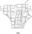
Fig. 1 is a front perspective view of an illustrative reinforcement in accordance with the present teachings. -
Fig. 2 is a rear perspective view of the reinforcement ofFig. 1 . -
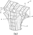
Fig. 3 is a top down perspective view of the reinforcement ofFig. 1 . -
Fig. 4 is cross sectional view of the reinforcement ofFig. 1 . -
Fig. 5 is rear elevational view of the reinforcement ofFig. 1 . - The present teachings meet one or more of the above needs by the improved devices and methods described herein. The explanations and illustrations presented herein are intended to acquaint others skilled in the art with the teachings, its principles, and its practical application. Those skilled in the art may adapt and apply the teachings in its numerous forms, as may be best suited to the requirements of a particular use. Accordingly, the specific embodiments of the present teachings as set forth are not intended as being exhaustive or limiting of the teachings. The scope of the teachings should, therefore, be determined not with reference to the above description, but should instead be determined with reference to the appended claims, along with the full scope of equivalents to which such claims are entitled.
- This application claims the benefit of the filing date of
U.S. Provisional Application Serial No. 62/449,410, filed on January 23, 2017 - The invention herein contemplates a unique approach for providing structural reinforcement in a vehicle structure, especially in areas where buckling of a cavity and/or of a reinforcement within a cavity is common. Such areas may include but may not be limited to, areas within or adjoining vehicle pillars and/or roof sections.
- The rigid polymeric structure may be formed of a moldable material, which may be any polymeric material. The rigid polymeric structure which may include a polyamide material. The rigid polymeric structure may be formed by pultrusion. The polymeric material may be a reinforced polymeric material. For example, the polymeric material may be a glass fiber reinforced material. The polymeric material may include a polyurethane. The polymeric material may be a thermoset material. The polymeric material may be a thermoplastic material. The polymeric material may be a thermoplastic epoxy material. The polymeric material may be a fiber reinforced thermoplastic epoxy material or a fiber-reinforced polyurethane material.
- The activatable material may be activated to expand, cure, or some combination thereof. The activatable material (e.g., expandable material) may be one or some combination of an adhesive, reinforcing and/or sealant material. The expandable material may be a material that experiences expansion and/or cure upon exposure to temperatures of between about 148.89°C to about 204.44°C (about 300°F to about 400°F) (i.e., temperatures typically experienced in automotive painting or coating operations). The expandable material may be foamed to a volume of at least 5% greater, at least 50% greater, at least 200% greater, at least 1000% greater, at least 2000% greater, at least 5000% greater or higher relative to the original unexpanded (e.g., green state) volume.
-
- The structural reinforcement may also be formed with a plurality of rib structures. The ribs may be arranged in at least one section of the structural reinforcement such that there are a plurality of ribs arranged equidistant from one another, substantially parallel to one another, substantially perpendicular to the longitudinal axis of the structural reinforcement, or some combination thereof.
- The upper portion may include a longitudinal axis that runs substantially perpendicular to the longitudinal axis of the structural reinforcement as a whole. The upper portion may include one or more ribs arranged substantially perpendicular to the longitudinal axis of the upper portion and thus substantially parallel to the longitudinal axis of the structural reinforcement as a whole.
- It is also possible that the expandable material may be located onto only select surfaces of the device. For example, the expandable material may be located onto a top or bottom surface of a portion (e.g., the central portion or side portion) of the device. It is possible that the expandable material be located onto surfaces of the portions that do not carry any rib structures.
- It is possible that the expandable material may be located in strips on the top and/or bottom surface that run parallel to the longitudinal axis of the structural reinforcement. It is also possible that the strips of expandable material on the top surface are offset from, yet still substantially parallel to the strips of expandable material on the bottom surface of the structural reinforcement.
- As shown for example in
Figs. 1-5 , thereinforcement structure 10 is shown having a rigidpolymeric structure 14. Portions of each of the polymeric 14 may include anexpandable material 12 located thereon. The reinforcement may further include a plurality ofrib structures 16. One ormore weld tabs 18 may be connected to an upper portion of the reinforcement. As shown for example inFigs. 1-5 , some of therib structures 16 may include anedge 20 that lies coplanar with a portion ofexpandable material 12. Theedge 20 that lies co-planar with theexpandable material 12 may be located on a portion of the structural reinforcement that includes an undulatingsurface 22. - The rigid polymeric structure may be formed by an injection molding step. The expandable material may be applied to the rigid polymeric structure by a second molding process (e.g., a two-shot molding process) whereby the adhesive material is injection molded onto the base reinforcing structure.
- Unless stated otherwise, dimensions and geometries of the various structures depicted herein are not intended to be restrictive of the invention, and other dimensions or geometries are possible. Plural structural components can be provided by a single integrated structure. Alternatively, a single integrated structure might be divided into separate plural components. In addition, while a feature of the present invention may have been described in the context of only one of the illustrated embodiments, such feature may be combined with one or more other features of other embodiments, for any given application. It will also be appreciated from the above that the fabrication of the unique structures herein and the operation thereof also constitute methods in accordance with the present invention.
- The preferred embodiment of the present invention has been disclosed. A person of ordinary skill in the art would realize however, that certain modifications would come within the teachings of this invention. Therefore, the following claims should be studied to determine the true scope and content of the invention.
- The explanations and illustrations presented herein are intended to acquaint others skilled in the art with the invention, its principles, and its practical application. Those skilled in the art may adapt and apply the invention in its numerous forms, as may be best suited to the requirements of a particular use. Accordingly, the specific embodiments of the present invention as set forth are not intended as being exhaustive or limiting of the invention. The scope of the invention should, therefore, be determined not with reference to the above description, but should instead be determined with reference to the appended claims, along with the full scope of equivalents to which such claims are entitled.
Claims (13)
- A structural reinforcement comprising:i) a rigid polymeric structure (14) having a longitudinal axis and including a lower portion and an upper portion each of the lower and upper portions including a top surface and bottom surface;ii) an expandable adhesive material (12) located onto a portion of each of the top and bottom surface of each of the upper and lower portions;iii) a central portion including at least three ribs (16) that are substantially parallel with one another and substantially equidistant from one another;wherein the at least three ribs include a top edge that is substantially co-planar with the expandable adhesive material prior to activation of the expandable adhesive material,wherein the at least three ribs (16) are arranged substantially perpendicular to the longitudinal axis,characterized in, that the lower portion includes at least one undulating surface that receives a layer of the expandable adhesive.
- The structural reinforcement of claim 1, including one or more weld tabs (18) located in the upper portion.
- The structural reinforcement of claim 2, wherein the weld tabs are overmolded by the rigid polymeric material.
- The structural reinforcement of any of claims 1 through 3, wherein the upper portion has a longitudinal axis that is substantially perpendicular to the longitudinal axis of the structural reinforcement (14).
- The structural reinforcement of claim 4, wherein the upper portion includes a plurality of ribs (16) arranged substantially perpendicular to the longitudinal axis of the upper portion.
- The structural reinforcement of claim 1, including strips of expandable material on each of the top surface and bottom surface of the upper portion and lower portion such that the strips are substantially parallel to one another.
- The structural reinforcement of claim 6, wherein the strips of expandable material on the top surface of the upper and lower portion are offset from the strips of expandable material on the bottom surface.
- The structural reinforcement of claim 7, wherein at least a portion of the top edges (20) of the at least three ribs that are co-planar with the expandable adhesive material are located in a portion of the structural reinforcement having an undulating surface.
- The structural reinforcement of claim 1, including one or more weld tabs located in the upper portion.
- The structural reinforcement of claim 9, wherein the weld tabs are overmolded by the rigid polymeric material.
- The structural reinforcement of any of claims 9 - 10, wherein the upper portion has a longitudinal axis that is substantially perpendicular to the longitudinal axis of the structural reinforcement.
- The structural reinforcement of any of claims 9 through 11, wherein the upper portion includes a plurality of ribs arranged substantially perpendicular to the longitudinal axis of the upper portion.
- The structural reinforcement of any of claims 9 through 11, wherein the strips of expandable material on the top surface of the upper and lower portion are offset from the strips of expandable material on the bottom surface.
Priority Applications (1)
| Application Number | Priority Date | Filing Date | Title |
|---|---|---|---|
| EP22181534.3A EP4101742A1 (en) | 2017-01-23 | 2018-01-23 | Pillar reinforcement |
Applications Claiming Priority (2)
| Application Number | Priority Date | Filing Date | Title |
|---|---|---|---|
| US201762449410P | 2017-01-23 | 2017-01-23 | |
| PCT/US2018/014916 WO2018136969A1 (en) | 2017-01-23 | 2018-01-23 | Pillar reinforcement |
Related Child Applications (1)
| Application Number | Title | Priority Date | Filing Date |
|---|---|---|---|
| EP22181534.3A Division EP4101742A1 (en) | 2017-01-23 | 2018-01-23 | Pillar reinforcement |
Publications (2)
| Publication Number | Publication Date |
|---|---|
| EP3571112A1 EP3571112A1 (en) | 2019-11-27 |
| EP3571112B1 true EP3571112B1 (en) | 2022-06-29 |
Family
ID=61163831
Family Applications (2)
| Application Number | Title | Priority Date | Filing Date |
|---|---|---|---|
| EP22181534.3A Pending EP4101742A1 (en) | 2017-01-23 | 2018-01-23 | Pillar reinforcement |
| EP18703439.2A Active EP3571112B1 (en) | 2017-01-23 | 2018-01-23 | Pillar reinforcement |
Family Applications Before (1)
| Application Number | Title | Priority Date | Filing Date |
|---|---|---|---|
| EP22181534.3A Pending EP4101742A1 (en) | 2017-01-23 | 2018-01-23 | Pillar reinforcement |
Country Status (5)
| Country | Link |
|---|---|
| US (1) | US10960934B2 (en) |
| EP (2) | EP4101742A1 (en) |
| CN (1) | CN110418750B (en) |
| BR (1) | BR112019015163B1 (en) |
| WO (1) | WO2018136969A1 (en) |
Families Citing this family (6)
| Publication number | Priority date | Publication date | Assignee | Title |
|---|---|---|---|---|
| WO2010054194A1 (en) * | 2008-11-07 | 2010-05-14 | Zephyros, Inc. | Hybrid reinforcement structure |
| EP3487749B1 (en) * | 2016-07-21 | 2021-10-06 | Zephyros, Inc. | Reinforcement structure |
| EP3568336B1 (en) * | 2017-01-11 | 2021-08-11 | Zephyros, Inc. | Reinforcing devices |
| CN114906232A (en) * | 2017-04-10 | 2022-08-16 | 沙特基础工业全球技术有限公司 | Hybrid structure and method of manufacture |
| US11312423B2 (en) * | 2017-11-15 | 2022-04-26 | Sika Technology Ag | Device for reinforcing a structural element |
| EP3486146B1 (en) * | 2017-11-15 | 2021-04-14 | Sika Technology Ag | Device for reinforcing and sealing a structural element |
Citations (14)
| Publication number | Priority date | Publication date | Assignee | Title |
|---|---|---|---|---|
| WO1997043501A1 (en) | 1996-05-10 | 1997-11-20 | Henkel Kommanditgesellschaft Auf Aktien | Internal reinforcement for hollow structural elements |
| WO2000013876A1 (en) | 1998-09-02 | 2000-03-16 | Henkel Corporation | Reinforcement of hollow sections using extrusions and a polymer binding layer |
| WO2001058741A1 (en) | 2000-02-11 | 2001-08-16 | L & L Products, Inc. | Structural reinforcement system for automotive vehicles |
| GB2375328A (en) | 2001-05-08 | 2002-11-13 | L & L Products | Reinforcing element for hollow structural member |
| WO2006066966A1 (en) | 2004-12-21 | 2006-06-29 | L & L Products Inc | Improvements in or relating to the structural reinforcement of vehicles |
| US7097794B2 (en) | 2002-04-15 | 2006-08-29 | Dow Global Technologies, Inc. | Vehicular structural members and method of making the members |
| EP1717078A2 (en) | 2005-04-28 | 2006-11-02 | L & L Products, Inc. | Door member for baffling, reinforcement or sealing |
| EP2011679A1 (en) | 2007-07-06 | 2009-01-07 | Ford Global Technologies, LLC | A striker reinforcement for an automotive door frame |
| US20090085379A1 (en) | 2007-09-28 | 2009-04-02 | Zephyros, Inc. | Reinforcement system for an automotive vehicle |
| WO2010097120A1 (en) | 2009-02-27 | 2010-09-02 | Sika Technology Ag | Structural reinforcement system |
| EP2463180A1 (en) | 2010-12-07 | 2012-06-13 | Sika Technology AG | Reinforcer with pre-applied bonding material |
| US8430448B2 (en) | 2008-11-07 | 2013-04-30 | Zephyros, Inc. | Hybrid reinforcement structure |
| US20150375800A1 (en) | 2014-06-30 | 2015-12-31 | Ford Global Technologies, Llc | Composite Reinforcement for Vehicle Body Structures |
| WO2018132579A1 (en) | 2017-01-11 | 2018-07-19 | Zephyros, Inc. | Reinforcing devices |
Family Cites Families (35)
| Publication number | Priority date | Publication date | Assignee | Title |
|---|---|---|---|---|
| US5884960A (en) | 1994-05-19 | 1999-03-23 | Henkel Corporation | Reinforced door beam |
| ZA991856B (en) | 1998-08-27 | 1999-09-22 | Henkel Corp | Storage-stable compositions useful for the production of structural foams. |
| US6387470B1 (en) | 1998-11-05 | 2002-05-14 | Sika Corporation | Sound deadening and structural reinforcement compositions and methods of using the same |
| JP2001088739A (en) * | 1999-09-24 | 2001-04-03 | Neoex Lab Inc | Hollow structure charging-in structure and method thereof |
| US6467834B1 (en) | 2000-02-11 | 2002-10-22 | L&L Products | Structural reinforcement system for automotive vehicles |
| US6786533B2 (en) | 2001-09-24 | 2004-09-07 | L&L Products, Inc. | Structural reinforcement system having modular segmented characteristics |
| US7318873B2 (en) * | 2002-03-29 | 2008-01-15 | Zephyros, Inc. | Structurally reinforced members |
| US7077460B2 (en) * | 2002-04-30 | 2006-07-18 | L&L Products, Inc. | Reinforcement system utilizing a hollow carrier |
| US6920693B2 (en) | 2002-07-24 | 2005-07-26 | L&L Products, Inc. | Dynamic self-adjusting assembly for sealing, baffling or structural reinforcement |
| US20040076831A1 (en) | 2002-10-02 | 2004-04-22 | L&L Products, Inc. | Synthetic material and methods of forming and applying same |
| US6811864B2 (en) | 2002-08-13 | 2004-11-02 | L&L Products, Inc. | Tacky base material with powder thereon |
| US6883858B2 (en) | 2002-09-10 | 2005-04-26 | L & L Products, Inc. | Structural reinforcement member and method of use therefor |
| US7125461B2 (en) * | 2003-05-07 | 2006-10-24 | L & L Products, Inc. | Activatable material for sealing, baffling or reinforcing and method of forming same |
| US7249415B2 (en) | 2003-06-26 | 2007-07-31 | Zephyros, Inc. | Method of forming members for sealing or baffling |
| GB0407047D0 (en) * | 2004-03-29 | 2004-04-28 | Nygaard Jens H S | Passenger carrying road vehicle and a strengthening member for a passenger carrying road vehicle |
| GB2415658A (en) * | 2004-06-21 | 2006-01-04 | L & L Products Inc | An overmoulding process |
| CN101233167B (en) * | 2005-07-01 | 2012-07-18 | Sika技术股份公司 | Solid thermally expansible material |
| US8087916B2 (en) * | 2005-12-15 | 2012-01-03 | Cemedine Henkel Co., Ltd. | Holding jig for a foamable material |
| GB0600901D0 (en) * | 2006-01-17 | 2006-02-22 | L & L Products Inc | Improvements in or relating to reinforcement of hollow profiles |
| US20080296164A1 (en) * | 2007-06-02 | 2008-12-04 | Lanxess Deutschland Gmbh | Reinforcement Element for a Vehicle Hollow Body |
| EP2251250A1 (en) * | 2009-05-05 | 2010-11-17 | Sika Technology AG | Bonding with adhesive beads or plots |
| DE102009054999A1 (en) * | 2009-12-18 | 2011-06-22 | Henkel AG & Co. KGaA, 40589 | composite component |
| CN104284831B (en) * | 2012-03-13 | 2016-10-12 | 泽费罗斯股份有限公司 | Load activates block piece |
| US8926005B2 (en) * | 2012-05-24 | 2015-01-06 | Zephyros, Inc. | Vehicle body structure cut zones |
| GB201318595D0 (en) * | 2013-10-21 | 2013-12-04 | Zephyros Inc | Improvements in or relating to laminates |
| DE102013022247B4 (en) * | 2013-12-09 | 2019-01-24 | Audi Ag | Vehicle body element |
| WO2015095325A1 (en) * | 2013-12-17 | 2015-06-25 | Zephyros, Inc. | Carrier with localized fibrous insert and methods |
| US10427346B2 (en) * | 2014-04-30 | 2019-10-01 | Zephyros, Inc. | Extruded reinforcements |
| US10449919B2 (en) * | 2014-05-19 | 2019-10-22 | Zephyros, Inc. | Method and device for reinforcement |
| CN107428095A (en) * | 2015-03-10 | 2017-12-01 | 泽菲罗斯有限公司 | Pultrusion part and its manufacture method |
| CN109982917B (en) * | 2016-07-28 | 2022-04-05 | 泽菲罗斯有限公司 | Multi-stage deformation reinforcement structure for absorbing impact |
| EP3612436B1 (en) * | 2017-04-21 | 2021-03-10 | Sika Technology AG | Reinforcing element |
| EP3665068B1 (en) * | 2017-08-07 | 2021-04-14 | Sika Technology AG | System of a sealed and reinforced structural element |
| EP3486147B1 (en) * | 2017-11-15 | 2021-01-13 | Sika Technology Ag | Device for reinforcing a structural element |
| US20200147899A1 (en) * | 2018-11-09 | 2020-05-14 | Zephyros, Inc. | Mechanical Interface for Retaining Adhesive Material |
-
2018
- 2018-01-23 US US16/480,089 patent/US10960934B2/en active Active
- 2018-01-23 CN CN201880018020.8A patent/CN110418750B/en active Active
- 2018-01-23 EP EP22181534.3A patent/EP4101742A1/en active Pending
- 2018-01-23 WO PCT/US2018/014916 patent/WO2018136969A1/en active Application Filing
- 2018-01-23 BR BR112019015163-0A patent/BR112019015163B1/en active IP Right Grant
- 2018-01-23 EP EP18703439.2A patent/EP3571112B1/en active Active
Patent Citations (14)
| Publication number | Priority date | Publication date | Assignee | Title |
|---|---|---|---|---|
| WO1997043501A1 (en) | 1996-05-10 | 1997-11-20 | Henkel Kommanditgesellschaft Auf Aktien | Internal reinforcement for hollow structural elements |
| WO2000013876A1 (en) | 1998-09-02 | 2000-03-16 | Henkel Corporation | Reinforcement of hollow sections using extrusions and a polymer binding layer |
| WO2001058741A1 (en) | 2000-02-11 | 2001-08-16 | L & L Products, Inc. | Structural reinforcement system for automotive vehicles |
| GB2375328A (en) | 2001-05-08 | 2002-11-13 | L & L Products | Reinforcing element for hollow structural member |
| US7097794B2 (en) | 2002-04-15 | 2006-08-29 | Dow Global Technologies, Inc. | Vehicular structural members and method of making the members |
| WO2006066966A1 (en) | 2004-12-21 | 2006-06-29 | L & L Products Inc | Improvements in or relating to the structural reinforcement of vehicles |
| EP1717078A2 (en) | 2005-04-28 | 2006-11-02 | L & L Products, Inc. | Door member for baffling, reinforcement or sealing |
| EP2011679A1 (en) | 2007-07-06 | 2009-01-07 | Ford Global Technologies, LLC | A striker reinforcement for an automotive door frame |
| US20090085379A1 (en) | 2007-09-28 | 2009-04-02 | Zephyros, Inc. | Reinforcement system for an automotive vehicle |
| US8430448B2 (en) | 2008-11-07 | 2013-04-30 | Zephyros, Inc. | Hybrid reinforcement structure |
| WO2010097120A1 (en) | 2009-02-27 | 2010-09-02 | Sika Technology Ag | Structural reinforcement system |
| EP2463180A1 (en) | 2010-12-07 | 2012-06-13 | Sika Technology AG | Reinforcer with pre-applied bonding material |
| US20150375800A1 (en) | 2014-06-30 | 2015-12-31 | Ford Global Technologies, Llc | Composite Reinforcement for Vehicle Body Structures |
| WO2018132579A1 (en) | 2017-01-11 | 2018-07-19 | Zephyros, Inc. | Reinforcing devices |
Non-Patent Citations (1)
| Title |
|---|
| SAMEER GUPTA: "Using CAE to evaluate a structural foam design for increasing roof strength", 8TH EUROPEAN LS-DYNA USER CONFERENCE, 1 May 2011 (2011-05-01), pages 1 - 12, XP093087121 |
Also Published As
| Publication number | Publication date |
|---|---|
| BR112019015163A2 (en) | 2020-03-24 |
| US20190382056A1 (en) | 2019-12-19 |
| WO2018136969A1 (en) | 2018-07-26 |
| EP3571112A1 (en) | 2019-11-27 |
| CN110418750A (en) | 2019-11-05 |
| US10960934B2 (en) | 2021-03-30 |
| BR112019015163B1 (en) | 2023-10-31 |
| EP4101742A1 (en) | 2022-12-14 |
| CN110418750B (en) | 2022-08-26 |
Similar Documents
| Publication | Publication Date | Title |
|---|---|---|
| EP3571112B1 (en) | Pillar reinforcement | |
| US10161543B2 (en) | Multi-part insert | |
| CN105857402B (en) | Vehicle frame structural member assembly and method | |
| KR101827233B1 (en) | Vehicle cross members and related methods | |
| KR101597852B1 (en) | Reinforcement assembly | |
| US9914490B2 (en) | Frame structure with at least one console for connecting further components, method for producing and motor vehicle body | |
| US8530015B2 (en) | Reinforcement of hollow profiles | |
| US20060233598A1 (en) | Interconnection unit for structural elements | |
| KR20010089819A (en) | Laminate reinforced beam with tapered polymer layer | |
| US11273872B2 (en) | Vehicle structural component and method for producing a vehicle structural component | |
| GB2521937A (en) | Body component for a vehicle and method for manufacturing a body component for a vehicle | |
| EP3568336B1 (en) | Reinforcing devices | |
| EP2289769B1 (en) | Structural reinforcer applied to cut-out area of structural member | |
| EP2450239B1 (en) | Method for connecting two objects and panel using said method | |
| CN111032494A (en) | System of sealed and reinforced structural elements | |
| US20160318220A1 (en) | Method for the production of a vehicle body element and vehicle body element | |
| KR101820547B1 (en) | Reinforcement aligned with axis of load | |
| CN108082068B (en) | Separator for motor vehicle | |
| JP2007290585A (en) | Frp molded body reinforcing structure, and its manufacturing method | |
| WO2020117784A1 (en) | Reinforcement with integrated stop device | |
| US20200269471A1 (en) | Method for producing a trim part for vehicles, using a temporary seal | |
| US10480556B1 (en) | Member joining method | |
| CN112638753B (en) | Device for reinforcing, sealing or damping a structural element |
Legal Events
| Date | Code | Title | Description |
|---|---|---|---|
| STAA | Information on the status of an ep patent application or granted ep patent |
Free format text: STATUS: UNKNOWN |
|
| STAA | Information on the status of an ep patent application or granted ep patent |
Free format text: STATUS: THE INTERNATIONAL PUBLICATION HAS BEEN MADE |
|
| PUAI | Public reference made under article 153(3) epc to a published international application that has entered the european phase |
Free format text: ORIGINAL CODE: 0009012 |
|
| STAA | Information on the status of an ep patent application or granted ep patent |
Free format text: STATUS: REQUEST FOR EXAMINATION WAS MADE |
|
| 17P | Request for examination filed |
Effective date: 20190823 |
|
| AK | Designated contracting states |
Kind code of ref document: A1 Designated state(s): AL AT BE BG CH CY CZ DE DK EE ES FI FR GB GR HR HU IE IS IT LI LT LU LV MC MK MT NL NO PL PT RO RS SE SI SK SM TR |
|
| AX | Request for extension of the european patent |
Extension state: BA ME |
|
| DAV | Request for validation of the european patent (deleted) | ||
| DAX | Request for extension of the european patent (deleted) | ||
| STAA | Information on the status of an ep patent application or granted ep patent |
Free format text: STATUS: EXAMINATION IS IN PROGRESS |
|
| 17Q | First examination report despatched |
Effective date: 20200626 |
|
| STAA | Information on the status of an ep patent application or granted ep patent |
Free format text: STATUS: EXAMINATION IS IN PROGRESS |
|
| STAA | Information on the status of an ep patent application or granted ep patent |
Free format text: STATUS: EXAMINATION IS IN PROGRESS |
|
| GRAP | Despatch of communication of intention to grant a patent |
Free format text: ORIGINAL CODE: EPIDOSNIGR1 |
|
| STAA | Information on the status of an ep patent application or granted ep patent |
Free format text: STATUS: GRANT OF PATENT IS INTENDED |
|
| INTG | Intention to grant announced |
Effective date: 20210727 |
|
| GRAJ | Information related to disapproval of communication of intention to grant by the applicant or resumption of examination proceedings by the epo deleted |
Free format text: ORIGINAL CODE: EPIDOSDIGR1 |
|
| STAA | Information on the status of an ep patent application or granted ep patent |
Free format text: STATUS: EXAMINATION IS IN PROGRESS |
|
| INTC | Intention to grant announced (deleted) | ||
| GRAP | Despatch of communication of intention to grant a patent |
Free format text: ORIGINAL CODE: EPIDOSNIGR1 |
|
| STAA | Information on the status of an ep patent application or granted ep patent |
Free format text: STATUS: GRANT OF PATENT IS INTENDED |
|
| INTG | Intention to grant announced |
Effective date: 20220126 |
|
| GRAS | Grant fee paid |
Free format text: ORIGINAL CODE: EPIDOSNIGR3 |
|
| GRAA | (expected) grant |
Free format text: ORIGINAL CODE: 0009210 |
|
| STAA | Information on the status of an ep patent application or granted ep patent |
Free format text: STATUS: THE PATENT HAS BEEN GRANTED |
|
| AK | Designated contracting states |
Kind code of ref document: B1 Designated state(s): AL AT BE BG CH CY CZ DE DK EE ES FI FR GB GR HR HU IE IS IT LI LT LU LV MC MK MT NL NO PL PT RO RS SE SI SK SM TR |
|
| REG | Reference to a national code |
Ref country code: CH Ref legal event code: EP |
|
| REG | Reference to a national code |
Ref country code: DE Ref legal event code: R096 Ref document number: 602018037272 Country of ref document: DE |
|
| REG | Reference to a national code |
Ref country code: AT Ref legal event code: REF Ref document number: 1501177 Country of ref document: AT Kind code of ref document: T Effective date: 20220715 |
|
| REG | Reference to a national code |
Ref country code: IE Ref legal event code: FG4D |
|
| REG | Reference to a national code |
Ref country code: LT Ref legal event code: MG9D |
|
| PG25 | Lapsed in a contracting state [announced via postgrant information from national office to epo] |
Ref country code: SE Free format text: LAPSE BECAUSE OF FAILURE TO SUBMIT A TRANSLATION OF THE DESCRIPTION OR TO PAY THE FEE WITHIN THE PRESCRIBED TIME-LIMIT Effective date: 20220629 Ref country code: NO Free format text: LAPSE BECAUSE OF FAILURE TO SUBMIT A TRANSLATION OF THE DESCRIPTION OR TO PAY THE FEE WITHIN THE PRESCRIBED TIME-LIMIT Effective date: 20220929 Ref country code: LT Free format text: LAPSE BECAUSE OF FAILURE TO SUBMIT A TRANSLATION OF THE DESCRIPTION OR TO PAY THE FEE WITHIN THE PRESCRIBED TIME-LIMIT Effective date: 20220629 Ref country code: HR Free format text: LAPSE BECAUSE OF FAILURE TO SUBMIT A TRANSLATION OF THE DESCRIPTION OR TO PAY THE FEE WITHIN THE PRESCRIBED TIME-LIMIT Effective date: 20220629 Ref country code: GR Free format text: LAPSE BECAUSE OF FAILURE TO SUBMIT A TRANSLATION OF THE DESCRIPTION OR TO PAY THE FEE WITHIN THE PRESCRIBED TIME-LIMIT Effective date: 20220930 Ref country code: FI Free format text: LAPSE BECAUSE OF FAILURE TO SUBMIT A TRANSLATION OF THE DESCRIPTION OR TO PAY THE FEE WITHIN THE PRESCRIBED TIME-LIMIT Effective date: 20220629 Ref country code: BG Free format text: LAPSE BECAUSE OF FAILURE TO SUBMIT A TRANSLATION OF THE DESCRIPTION OR TO PAY THE FEE WITHIN THE PRESCRIBED TIME-LIMIT Effective date: 20220929 |
|
| REG | Reference to a national code |
Ref country code: NL Ref legal event code: MP Effective date: 20220629 |
|
| REG | Reference to a national code |
Ref country code: AT Ref legal event code: MK05 Ref document number: 1501177 Country of ref document: AT Kind code of ref document: T Effective date: 20220629 |
|
| PG25 | Lapsed in a contracting state [announced via postgrant information from national office to epo] |
Ref country code: RS Free format text: LAPSE BECAUSE OF FAILURE TO SUBMIT A TRANSLATION OF THE DESCRIPTION OR TO PAY THE FEE WITHIN THE PRESCRIBED TIME-LIMIT Effective date: 20220629 Ref country code: LV Free format text: LAPSE BECAUSE OF FAILURE TO SUBMIT A TRANSLATION OF THE DESCRIPTION OR TO PAY THE FEE WITHIN THE PRESCRIBED TIME-LIMIT Effective date: 20220629 |
|
| PG25 | Lapsed in a contracting state [announced via postgrant information from national office to epo] |
Ref country code: NL Free format text: LAPSE BECAUSE OF FAILURE TO SUBMIT A TRANSLATION OF THE DESCRIPTION OR TO PAY THE FEE WITHIN THE PRESCRIBED TIME-LIMIT Effective date: 20220629 |
|
| PG25 | Lapsed in a contracting state [announced via postgrant information from national office to epo] |
Ref country code: SM Free format text: LAPSE BECAUSE OF FAILURE TO SUBMIT A TRANSLATION OF THE DESCRIPTION OR TO PAY THE FEE WITHIN THE PRESCRIBED TIME-LIMIT Effective date: 20220629 Ref country code: SK Free format text: LAPSE BECAUSE OF FAILURE TO SUBMIT A TRANSLATION OF THE DESCRIPTION OR TO PAY THE FEE WITHIN THE PRESCRIBED TIME-LIMIT Effective date: 20220629 Ref country code: RO Free format text: LAPSE BECAUSE OF FAILURE TO SUBMIT A TRANSLATION OF THE DESCRIPTION OR TO PAY THE FEE WITHIN THE PRESCRIBED TIME-LIMIT Effective date: 20220629 Ref country code: PT Free format text: LAPSE BECAUSE OF FAILURE TO SUBMIT A TRANSLATION OF THE DESCRIPTION OR TO PAY THE FEE WITHIN THE PRESCRIBED TIME-LIMIT Effective date: 20221031 Ref country code: ES Free format text: LAPSE BECAUSE OF FAILURE TO SUBMIT A TRANSLATION OF THE DESCRIPTION OR TO PAY THE FEE WITHIN THE PRESCRIBED TIME-LIMIT Effective date: 20220629 Ref country code: EE Free format text: LAPSE BECAUSE OF FAILURE TO SUBMIT A TRANSLATION OF THE DESCRIPTION OR TO PAY THE FEE WITHIN THE PRESCRIBED TIME-LIMIT Effective date: 20220629 Ref country code: AT Free format text: LAPSE BECAUSE OF FAILURE TO SUBMIT A TRANSLATION OF THE DESCRIPTION OR TO PAY THE FEE WITHIN THE PRESCRIBED TIME-LIMIT Effective date: 20220629 |
|
| PG25 | Lapsed in a contracting state [announced via postgrant information from national office to epo] |
Ref country code: PL Free format text: LAPSE BECAUSE OF FAILURE TO SUBMIT A TRANSLATION OF THE DESCRIPTION OR TO PAY THE FEE WITHIN THE PRESCRIBED TIME-LIMIT Effective date: 20220629 Ref country code: IS Free format text: LAPSE BECAUSE OF FAILURE TO SUBMIT A TRANSLATION OF THE DESCRIPTION OR TO PAY THE FEE WITHIN THE PRESCRIBED TIME-LIMIT Effective date: 20221029 |
|
| REG | Reference to a national code |
Ref country code: DE Ref legal event code: R026 Ref document number: 602018037272 Country of ref document: DE |
|
| PG25 | Lapsed in a contracting state [announced via postgrant information from national office to epo] |
Ref country code: AL Free format text: LAPSE BECAUSE OF FAILURE TO SUBMIT A TRANSLATION OF THE DESCRIPTION OR TO PAY THE FEE WITHIN THE PRESCRIBED TIME-LIMIT Effective date: 20220629 |
|
| PLBI | Opposition filed |
Free format text: ORIGINAL CODE: 0009260 |
|
| PLAX | Notice of opposition and request to file observation + time limit sent |
Free format text: ORIGINAL CODE: EPIDOSNOBS2 |
|
| PG25 | Lapsed in a contracting state [announced via postgrant information from national office to epo] |
Ref country code: DK Free format text: LAPSE BECAUSE OF FAILURE TO SUBMIT A TRANSLATION OF THE DESCRIPTION OR TO PAY THE FEE WITHIN THE PRESCRIBED TIME-LIMIT Effective date: 20220629 Ref country code: CZ Free format text: LAPSE BECAUSE OF FAILURE TO SUBMIT A TRANSLATION OF THE DESCRIPTION OR TO PAY THE FEE WITHIN THE PRESCRIBED TIME-LIMIT Effective date: 20220629 |
|
| PGFP | Annual fee paid to national office [announced via postgrant information from national office to epo] |
Ref country code: FR Payment date: 20230124 Year of fee payment: 6 |
|
| 26 | Opposition filed |
Opponent name: SIKA TECHNOLOGY AG Effective date: 20230328 |
|
| PGFP | Annual fee paid to national office [announced via postgrant information from national office to epo] |
Ref country code: DE Payment date: 20230123 Year of fee payment: 6 |
|
| P01 | Opt-out of the competence of the unified patent court (upc) registered |
Effective date: 20230524 |
|
| PLBB | Reply of patent proprietor to notice(s) of opposition received |
Free format text: ORIGINAL CODE: EPIDOSNOBS3 |
|
| PG25 | Lapsed in a contracting state [announced via postgrant information from national office to epo] |
Ref country code: SI Free format text: LAPSE BECAUSE OF FAILURE TO SUBMIT A TRANSLATION OF THE DESCRIPTION OR TO PAY THE FEE WITHIN THE PRESCRIBED TIME-LIMIT Effective date: 20220629 |
|
| REG | Reference to a national code |
Ref country code: CH Ref legal event code: PL |
|
| GBPC | Gb: european patent ceased through non-payment of renewal fee |
Effective date: 20230123 |
|
| PG25 | Lapsed in a contracting state [announced via postgrant information from national office to epo] |
Ref country code: LU Free format text: LAPSE BECAUSE OF NON-PAYMENT OF DUE FEES Effective date: 20230123 |
|
| REG | Reference to a national code |
Ref country code: BE Ref legal event code: MM Effective date: 20230131 |
|
| PG25 | Lapsed in a contracting state [announced via postgrant information from national office to epo] |
Ref country code: LI Free format text: LAPSE BECAUSE OF NON-PAYMENT OF DUE FEES Effective date: 20230131 Ref country code: GB Free format text: LAPSE BECAUSE OF NON-PAYMENT OF DUE FEES Effective date: 20230123 Ref country code: CH Free format text: LAPSE BECAUSE OF NON-PAYMENT OF DUE FEES Effective date: 20230131 |
|
| PG25 | Lapsed in a contracting state [announced via postgrant information from national office to epo] |
Ref country code: BE Free format text: LAPSE BECAUSE OF NON-PAYMENT OF DUE FEES Effective date: 20230131 |
|
| PG25 | Lapsed in a contracting state [announced via postgrant information from national office to epo] |
Ref country code: IT Free format text: LAPSE BECAUSE OF FAILURE TO SUBMIT A TRANSLATION OF THE DESCRIPTION OR TO PAY THE FEE WITHIN THE PRESCRIBED TIME-LIMIT Effective date: 20220629 Ref country code: IE Free format text: LAPSE BECAUSE OF NON-PAYMENT OF DUE FEES Effective date: 20230123 |