EP3571066B1 - Automatic hinged towing device especially for passenger cars - Google Patents
Automatic hinged towing device especially for passenger cars Download PDFInfo
- Publication number
- EP3571066B1 EP3571066B1 EP18711215.6A EP18711215A EP3571066B1 EP 3571066 B1 EP3571066 B1 EP 3571066B1 EP 18711215 A EP18711215 A EP 18711215A EP 3571066 B1 EP3571066 B1 EP 3571066B1
- Authority
- EP
- European Patent Office
- Prior art keywords
- cam
- rotary shaft
- section
- actuator
- towing device
- Prior art date
- Legal status (The legal status is an assumption and is not a legal conclusion. Google has not performed a legal analysis and makes no representation as to the accuracy of the status listed.)
- Active
Links
Images




Classifications
-
- B—PERFORMING OPERATIONS; TRANSPORTING
- B60—VEHICLES IN GENERAL
- B60D—VEHICLE CONNECTIONS
- B60D1/00—Traction couplings; Hitches; Draw-gear; Towing devices
- B60D1/01—Traction couplings or hitches characterised by their type
- B60D1/06—Ball-and-socket hitches
-
- B—PERFORMING OPERATIONS; TRANSPORTING
- B60—VEHICLES IN GENERAL
- B60D—VEHICLE CONNECTIONS
- B60D1/00—Traction couplings; Hitches; Draw-gear; Towing devices
- B60D1/48—Traction couplings; Hitches; Draw-gear; Towing devices characterised by the mounting
- B60D1/54—Traction couplings; Hitches; Draw-gear; Towing devices characterised by the mounting collapsible or retractable when not in use, e.g. hide-away hitches
-
- B—PERFORMING OPERATIONS; TRANSPORTING
- B60—VEHICLES IN GENERAL
- B60D—VEHICLE CONNECTIONS
- B60D1/00—Traction couplings; Hitches; Draw-gear; Towing devices
- B60D1/58—Auxiliary devices
- B60D1/62—Auxiliary devices involving supply lines, electric circuits or the like
Definitions
- the invention primarily relates to passenger cars, specifically a hinged towing device.
- Towing devices with a hook that is firmly attached to the body supporting elements with a towing device removable hook, and hinged towing device.
- the hinged towing devices are controlled either mechanically, by means of a cable or electrically powered actuator.
- multi-actuator designs are known, the basis of which rests in the use of a rigid connection between the cam and rotary shaft. These hinged towing device designs are heavy and have a complex structure.
- the hinged towing devices use their multiple locking elements to lock their towing arm.
- the disadvantage of these solutions is the fact that their manufacturing precision cannot guarantee geometric concentricity of the interlocking components.
- a trailer coupling comprising a mounting unit which is fixedly connectable to a vehicle body; a pivot bearing unit, provided on the mounting unit, having a pivot bearing base which is fixedly connected to the mounting unit, and having a pivot element which is pivotable about a pivot axis, relative to the pivot bearing base, between a working position and a rest position, and is displaceable in the direction of the pivot axis between a fixed position and a pivot position; a ball neck which at one end is mounted on the pivot element and which at the other end carries a coupling ball, and which, due to the pivotability of the pivot element, is pivotable about the pivot axis between the working position and the rest position, and due to the displaceability of the pivot element is displaceable between the fixed position and the pivot position; a fixing unit which, in the fixed position of the pivot element, fixes the pivot element, and thus also the ball neck, relative to the pivot bearing base in a rotationally fixed manner by means of positive-fit elements
- the main components of the hinged towing device include its rotary shaft. One end of it features a forced-on towing arm, and the other one features a ball.
- a bearing diameter for a needle bearing mounting In the middle part of the rotary shaft, there is a bearing diameter for a needle bearing mounting. This diameter is coupled with the rotary shaft mount formed by an axial bearing. The axial forces are absorbed from one side by the outer ring of the needle bearing, and on the other side by the locking lid. The outer ring of the needle bearing and locking lid are firmly connected to the towing device beam flange.
- the part of the rotary shaft behind the mount is drilled. The holes are perpendicular to the axis of rotation, forming a guide for the balls that move simultaneously with the rotary shaft.
- one of the balls In the folded or raised position, one of the balls always controls the end switch.
- the balls reach the small diameter of the expansion spindle and immerse into the rotary shaft guiding diameter, at the other end of which an extension is formed which, when the cam rotates, only touches the cam carrier, and the shaft rotates together with the cam into the raised or folded position.
- a hole is created in the longitudinal axis of the rotary shaft. It serves as a guide for the expansion part of the spindle and for the main and backup springs.
- the spindle moves in the axis of rotation and rotates with the rotary shaft.
- the spindle is still pressed in one direction by the springs; in the other direction it is controlled (shifted) by the axial cam connected to the actuator via a torque clutch.
- the expansion spindle features its guiding, conical, safety, small diameter, fatigue relief, and push-off sections.
- the cam together with the torque clutch, is mounted in a radial bearing and then in a plastic housing to which the actuator is screwed.
- the cam actuator features a rotary axis parallel to the rotary shaft axis but shifted by the cam span diameter radius.
- the tilting mechanism including the actuator and end switches protected by covers, is sealed with a gasket and several "O" rings.
- the actuator rotates the cam to the left (folded) or to the right (raised).
- the cam actuates the expansion spindle, which shifts, and the mechanism gets unlocked.
- the shaft extension contacts the cam carrier formed on its periphery and the shaft of the appropriate geometric image in the lock cover, the balls fit into the slots of the locking cap and move the resilient contacts so that the end switches are switched off, and the rotation of the actuator, which is secured by the torque clutch against overloading, is stopped.
- the clutch is set so that the maximum force on the towing arm circumference does not exceed the prescribed force.
- the corresponding torque of the torque clutch is formed by disc springs that are pre-stressed by a nut.”
- the torque clutch is mounted in the cam and performs the safety function when the towing arm moves. If the towing arm is caught by some obstacle, the actuator is time-limited so that the towing arm movement is interrupted after a set time, and after the obstacle has been removed, the device must be restarted.
- Another safety feature is the safety lock that ensures complete unlocking of the mechanism by moving the expansion spindle to its position where the balls move from the conical section of the expansion spindle to its cylindrical section, and the expansion spindle with its locking pawl get locked, and the balls touch the expansion spindle cylindrical diameter and get loose in their grooves.
- the towing arm features a slight play of the locking mechanism, but the mechanism cannot be fully unlocked when the balls reach the cylindrical section of the expansion spindle.
- the end switches (sensors or switches) are switched off, and the electronics indicate a fault.
- the automatic towing device unfolding may be started in multiple ways. One may use the buttons inside a car or on the rear car lid or even remotely, possibly through a radar or ultrasonic sensor or other means. When the electrical plug is plugged into the socket, the electronics shut off the electrical circuit powering the actuator so that the towing arm cannot be raised or folded. This is not possible even while driving.
- the main components of the hinged mechanism include the pivot shaft (40), one end of which features its forced-on towing arm (14) locked with pins (43). Its other end features the ISO ball (50).
- the needle bearing (8) mounted, behind which is the rotary shaft (40) mount (41) to absorb axial forces. The axial forces are absorbed from one side by the needle bearing (8) outer ring (9) and from the other side by the locking cap (20).
- the outer ring (9) of the needle bearing (8) and the locking cap (20) are firmly connected to the flange (26) of the towing device beam (80).
- the openings are perpendicular to the rotary shaft (40) axis, forming a guide (76) for the balls (54) that move together with the rotary shaft (40).
- one of the balls (54) In the folded or raised position, one of the balls (54) always actuates the end switch (23, 24) in the given geometrical arrangement of the locking cap (20).
- the balls (54) reach the small diameter (83) of the expansion spindle (52) and move in the guide diameter of the rotary shaft (40) (see Fig. 7 ) whose other end features the extension (42) (see Fig.
- a hole is created in the rotary shaft (40) longitudinal axis.
- the hole acts as a guide for the expansion section of the spindle (52) and for the main spring (77) and backup spring (78).
- the expansion spindle (52) moves in the rotation axis and turns together with the rotary shaft (40).
- the spindle (52) is constantly pressed in one direction by two springs (77 and 78), and in the other direction it is controlled (shifted) by the axial cam (16) connected to the actuator (17) via the torque clutch (72).
- the expansion spindle (52) features its guiding section (81), springs (77 and 78), ball conical section (82) for ball (54) control, safety section (28) that prevents any undesirable ball (54) gripping, small diameter (83) for ball unlocking, relief (84) for the clutch latch (13), and the push-off section (12).
- the cam (16) together with the torque clutch (72) is mounted in the radial bearing (75) and also in the plastic housing (27) to which the actuator (17) is screwed.
- the actuator (17) with cam (16) feature their rotational axis parallel to the rotary shaft (40) axis; however, it is displaced by the cam (16) span diameter radius (see Fig. 8 ).
- the hinged mechanism including the actuator (17) and end switches (23 and 24) protected with caps (25), features its IP 67 protection. It is sealed with a gasket (79) and several "O" rings.
- the actuator (17) turns to the left (folded) or to the right (raised). It turns the cam (16) and moves the expansion spindle (52).
- the mechanism becomes fully unlocked (see Fig. 7 ), while simultaneously engaging the shaft extension (42) with the cam carrier (16) formed on its perimeter.
- the balls (54) engage in the locking cap (20) grooves (58) and move the resilient contacts (21 and 22) by disabling the limit switches (23 and 24). It stops the rotation of the actuator (17), which is protected by the torque clutch (72) against overload.
- the clutch (72) is set so that the maximum force on the towing arm (14) circumference does not exceed the prescribed force.
- the corresponding torque of the torque clutch (72) is formed by disc springs (70) that are pre- stressed by a nut (71).
- the torque clutch (72) is mounted in the cam (16) and performs the safety function when the towing arm (14) moves. If the towing arm (14) is caught by some obstacle, the actuator (17) is time-limited so that the towing arm (14) movement is interrupted after a set time, and after the obstacle has been removed, the device must be restarted.
- Another safety feature is the safety lock (73) (see Fig.
- the electronics shut off the electrical circuit powering the actuator so that the towing arm (14) cannot be raised or folded. This is not possible even while driving.
Landscapes
- Engineering & Computer Science (AREA)
- Transportation (AREA)
- Mechanical Engineering (AREA)
- Mechanical Operated Clutches (AREA)
- Lock And Its Accessories (AREA)
- Pivots And Pivotal Connections (AREA)
Description
- The invention primarily relates to passenger cars, specifically a hinged towing device.
- Three types of towing devices are currently being used. Towing devices with a hook that is firmly attached to the body supporting elements, with a towing device removable hook, and hinged towing device. The hinged towing devices are controlled either mechanically, by means of a cable or electrically powered actuator. In the case of hinged devices with actuators, multi-actuator designs are known, the basis of which rests in the use of a rigid connection between the cam and rotary shaft. These hinged towing device designs are heavy and have a complex structure.
- The hinged towing devices use their multiple locking elements to lock their towing arm. The disadvantage of these solutions is the fact that their manufacturing precision cannot guarantee geometric concentricity of the interlocking components. These deficiencies are solved through, for example, additional compensating elements, which make these solutions more expensive.
- From the document
US 2013/093162 A1 a trailer coupling is known comprising a mounting unit which is fixedly connectable to a vehicle body; a pivot bearing unit, provided on the mounting unit, having a pivot bearing base which is fixedly connected to the mounting unit, and having a pivot element which is pivotable about a pivot axis, relative to the pivot bearing base, between a working position and a rest position, and is displaceable in the direction of the pivot axis between a fixed position and a pivot position; a ball neck which at one end is mounted on the pivot element and which at the other end carries a coupling ball, and which, due to the pivotability of the pivot element, is pivotable about the pivot axis between the working position and the rest position, and due to the displaceability of the pivot element is displaceable between the fixed position and the pivot position; a fixing unit which, in the fixed position of the pivot element, fixes the pivot element, and thus also the ball neck, relative to the pivot bearing base in a rotationally fixed manner by means of positive-fit elements, and in the pivot position allows pivoting; and a locking unit, which acts axially against a displacement in the direction of the pivot axis, by means of which, in the fixed position, the fixing unit is fixable against a movement in the direction of the pivot position, the fixing unit having a stationary first toothed segment which is fixedly connected to the pivot bearing base, by means of which a first toothed segment which in the working position is connected to the pivot element in a rotationally fixed manner and pivots together with same, is engageable by displacing the pivot element from the pivot position into the fixed position, and is disengageable by displacing the pivot element from the fixed position into the pivot position. - The aforementioned deficiencies are to a large extent resolved by the arrangement per this invention when the hinged towing device is designed in such a way that the locking mechanism functions and the hinged arm is tilted automatically through only one actuator and without the use of any rigid connection between the cam and rotary shaft when the cam unlocks the locking; mechanism while turning the rotary shaft to its upright or folded position.
- The main components of the hinged towing device include its rotary shaft. One end of it features a forced-on towing arm, and the other one features a ball. In the middle part of the rotary shaft, there is a bearing diameter for a needle bearing mounting. This diameter is coupled with the rotary shaft mount formed by an axial bearing. The axial forces are absorbed from one side by the outer ring of the needle bearing, and on the other side by the locking lid. The outer ring of the needle bearing and locking lid are firmly connected to the towing device beam flange. The part of the rotary shaft behind the mount is drilled. The holes are perpendicular to the axis of rotation, forming a guide for the balls that move simultaneously with the rotary shaft. In the folded or raised position, one of the balls always controls the end switch. When the mechanism is unlocked, the balls reach the small diameter of the expansion spindle and immerse into the rotary shaft guiding diameter, at the other end of which an extension is formed which, when the cam rotates, only touches the cam carrier, and the shaft rotates together with the cam into the raised or folded position. A hole is created in the longitudinal axis of the rotary shaft. It serves as a guide for the expansion part of the spindle and for the main and backup springs. The spindle moves in the axis of rotation and rotates with the rotary shaft. The spindle is still pressed in one direction by the springs; in the other direction it is controlled (shifted) by the axial cam connected to the actuator via a torque clutch.
- The expansion spindle features its guiding, conical, safety, small diameter, fatigue relief, and push-off sections. The cam, together with the torque clutch, is mounted in a radial bearing and then in a plastic housing to which the actuator is screwed. The cam actuator features a rotary axis parallel to the rotary shaft axis but shifted by the cam span diameter radius. The tilting mechanism, including the actuator and end switches protected by covers, is sealed with a gasket and several "O" rings.
- Thanks to this design, the following functions of the hinged towing device are achieved:
The actuator rotates the cam to the left (folded) or to the right (raised). The cam actuates the expansion spindle, which shifts, and the mechanism gets unlocked. Then, the shaft extension contacts the cam carrier formed on its periphery and the shaft of the appropriate geometric image in the lock cover, the balls fit into the slots of the locking cap and move the resilient contacts so that the end switches are switched off, and the rotation of the actuator, which is secured by the torque clutch against overloading, is stopped. The clutch is set so that the maximum force on the towing arm circumference does not exceed the prescribed force. The corresponding torque of the torque clutch is formed by disc springs that are pre-stressed by a nut." The torque clutch is mounted in the cam and performs the safety function when the towing arm moves. If the towing arm is caught by some obstacle, the actuator is time-limited so that the towing arm movement is interrupted after a set time, and after the obstacle has been removed, the device must be restarted. Another safety feature is the safety lock that ensures complete unlocking of the mechanism by moving the expansion spindle to its position where the balls move from the conical section of the expansion spindle to its cylindrical section, and the expansion spindle with its locking pawl get locked, and the balls touch the expansion spindle cylindrical diameter and get loose in their grooves. In this position, the towing arm features a slight play of the locking mechanism, but the mechanism cannot be fully unlocked when the balls reach the cylindrical section of the expansion spindle. The end switches (sensors or switches) are switched off, and the electronics indicate a fault. The automatic towing device unfolding may be started in multiple ways. One may use the buttons inside a car or on the rear car lid or even remotely, possibly through a radar or ultrasonic sensor or other means. When the electrical plug is plugged into the socket, the electronics shut off the electrical circuit powering the actuator so that the towing arm cannot be raised or folded. This is not possible even while driving. - The technical solution based on this invention will be described in more detail by an embodiment. The figures show as cross-sections:
- Fig. 1
- the expansion spindle,
- Fig. 2
- the cam in its initial position,
- Fig. 3
- the cam turned by 180 deg. in its intermediate position,
- Fig. 4
- the cam turned to its engaged position,
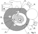
- Fig. 5
- the cam in its end position,
- Fig. 6
- a sectional view of the locked device,
- Fig. 7
- a sectional view of the unlocked device,
- Fig. 8
- a sectional view of the cam and torque clutch,
- Fig. 9
- a detail cross-section of the cam and torque clutch,
- Fig. 10
- a sectional view of the device when the cam is turned by 90°, and the rotary shaft extension may be seen, and
- Fig. 11
- shows a cross-section of the device showing the expansion spindle secured against the total mechanism unlocking by a locking device.
- The main components of the hinged mechanism include the pivot shaft (40), one end of which features its forced-on towing arm (14) locked with pins (43). Its other end features the ISO ball (50). In the middle of the pivot shaft (40), there is the needle bearing (8) mounted, behind which is the rotary shaft (40) mount (41) to absorb axial forces. The axial forces are absorbed from one side by the needle bearing (8) outer ring (9) and from the other side by the locking cap (20). The outer ring (9) of the needle bearing (8) and the locking cap (20) are firmly connected to the flange (26) of the towing device beam (80). In the rotary shaft (40) section behind the mount (41), the openings are perpendicular to the rotary shaft (40) axis, forming a guide (76) for the balls (54) that move together with the rotary shaft (40). In the folded or raised position, one of the balls (54) always actuates the end switch (23, 24) in the given geometrical arrangement of the locking cap (20). When the mechanism is unlocked, the balls (54) reach the small diameter (83) of the expansion spindle (52) and move in the guide diameter of the rotary shaft (40) (see
Fig. 7 ) whose other end features the extension (42) (seeFig. 10 ), which, when the cam carrier (16) is rotated only touches the cam carrier (16), and the shaft (40) turns together with the cam (16) to the raised or folded position (seeFigures 2 ,3 ,4 , and5 ). A hole is created in the rotary shaft (40) longitudinal axis. The hole acts as a guide for the expansion section of the spindle (52) and for the main spring (77) and backup spring (78). The expansion spindle (52) moves in the rotation axis and turns together with the rotary shaft (40). The spindle (52) is constantly pressed in one direction by two springs (77 and 78), and in the other direction it is controlled (shifted) by the axial cam (16) connected to the actuator (17) via the torque clutch (72). - The expansion spindle (52) features its guiding section (81), springs (77 and 78), ball conical section (82) for ball (54) control, safety section (28) that prevents any undesirable ball (54) gripping, small diameter (83) for ball unlocking, relief (84) for the clutch latch (13), and the push-off section (12). The cam (16) together with the torque clutch (72) is mounted in the radial bearing (75) and also in the plastic housing (27) to which the actuator (17) is screwed. The actuator (17) with cam (16) feature their rotational axis parallel to the rotary shaft (40) axis; however, it is displaced by the cam (16) span diameter radius (see
Fig. 8 ). The hinged mechanism, including the actuator (17) and end switches (23 and 24) protected with caps (25), features its IP 67 protection. It is sealed with a gasket (79) and several "O" rings. - Thanks to this design, the following functions of the hinged towing device are achieved:
The actuator (17) turns to the left (folded) or to the right (raised). It turns the cam (16) and moves the expansion spindle (52). The mechanism becomes fully unlocked (seeFig. 7 ), while simultaneously engaging the shaft extension (42) with the cam carrier (16) formed on its perimeter. Once the rotary shaft (40) reaches the geometrical arrangement in the locking cap (20), the balls (54) engage in the locking cap (20) grooves (58) and move the resilient contacts (21 and 22) by disabling the limit switches (23 and 24). It stops the rotation of the actuator (17), which is protected by the torque clutch (72) against overload. The clutch (72) is set so that the maximum force on the towing arm (14) circumference does not exceed the prescribed force. The corresponding torque of the torque clutch (72) is formed by disc springs (70) that are pre- stressed by a nut (71). The torque clutch (72) is mounted in the cam (16) and performs the safety function when the towing arm (14) moves. If the towing arm (14) is caught by some obstacle, the actuator (17) is time-limited so that the towing arm (14) movement is interrupted after a set time, and after the obstacle has been removed, the device must be restarted. Another safety feature is the safety lock (73) (seeFig. 11 ) that ensures complete unlocking of the mechanism by moving the expansion spindle (52) to its position where the balls (54) move from the conical section (82) of the expansion spindle (52) to its cylindrical section (28) (seeFig. 11 ), and the expansion spindle (52) with its locking pawl (13) gets locked, and the balls (54) touch the expansion spindle cylindrical diameter (28) and get loose in their grooves (58). In this position, the towing arm (14) features a slight play of the locking mechanism, but the mechanism cannot be fully unlocked when the balls (54) reach the cylindrical section (28) of the expansion spindle (52). The end switches (23, 24) (sensors or switches) are switched off, and the electronics indicate a fault. The automatic towing device unfolding may be started in multiple ways. One may use the buttons inside a car or on the rear car lid or even remotely, possibly through a radar or ultrasonic sensor or other means. When the electrical plug is plugged into the socket, the electronics shut off the electrical circuit powering the actuator so that the towing arm (14) cannot be raised or folded. This is not possible even while driving. - This solution is particularly usable in the automotive industry.
Claims (4)
- An automatic actuator-controlled (17) hinged towing device comprising a towing arm (14), a needle bearing (8), a mount (41) of the rotary shaft (40), locking cap (20), a towing device beam (80), a towing device beam flange (26), balls (54), at least one end switch (23, 24), a cam (16), an expansion spindle (52), main spring (77) and backup spring (78), an actuator (17), a cam (16) pins (43) and outer ring (9) with- a rotary shaft (40), to which at one end the towing arm (14) is pressed on, wherein the needle bearing (8) is mounted in the middle section of the rotary shaft (40) , wherein behind the needle bearing (8), there is the mount (41) for the rotary shaft (40), wherein the mount (41) is connected to the outer ring (9) of the needle bearing (8) and on the other side it is connected to the locking cap (20), wherein the outer ring (9) and the locking cap (20) are firmly connected to the towing device beam (80) flange (26), wherein in the bottom section of the rotary shaft (40) behind the mount (41), there are holes perpendicular to the rotary shaft (40) rotation axis, wherein the rotary shaft (40) forms a guide (76) for the balls (54), wherein at least one of the balls (54) is in the respective geometrical arrangement of the locking cap (20) opposite to the at least one end switch (23, 24), wherein on the other end, there is an extension (42), which is connected to the cam (16),characterized characterized in
that the towing arm (14) is secured by the pins (43) and in that in the longitudinal axis of the rotary shaft (40), the rotary shaft (40) comprising a hole receiving the expansion spindle (52), the main spring (77) and the backup spring (78), wherein the expansion spindle (52) is actuated in one direction by the springs (77, 78) and in the other direction by the axial cam (16) connected to the actuator (17) stored in the cam (16). - The automatic hinged towing device of claim 1 comprising a guiding section (81), a conical section (82), a safety section (28), a small diameter (83) section, a relief (84) section, a protection latch (13) and a push-off section (12) the expansion spindle (52) comprising the guiding section (81) for guiding the springs (77, 78), followed by the conical section (82) to control the balls (54), followed by the safety section (28) that prevents any undesirable ball (54) gripping, followed by the small diameter (83) section for unlocking the balls (54), followed by the relief (84) section for the protection latch (13) and followed by the push-off section (12).
- The automatic hinged towing device of claim 1 comprising a cam (16) and a circumferential carrier, wherein the cam (16) actuator's (17) rotation axis is parallel to the rotary shaft (40) axis that is shifted by the cam (16) span diameter radius, wherein the cam (16) comprises the circumferential carrier to actuate the rotary shaft (40) extension (42).
- The automatic hinged towing device of one of the previous claims comprising a torque clutch (72), disc springs (70), a nut (71), wherein the actuator (17) is locked by the torque clutch (72) and disc springs (70) against overloading, wherein the disc springs (70) are pre-stressed by the nut (71) and the torque clutch (72) is housed in the cam (16) to secure safety when the towing arm (14) moves.
Priority Applications (1)
| Application Number | Priority Date | Filing Date | Title |
|---|---|---|---|
| PL18711215T PL3571066T3 (en) | 2017-01-20 | 2018-01-17 | Automatic hinged towing device especially for passenger cars |
Applications Claiming Priority (2)
| Application Number | Priority Date | Filing Date | Title |
|---|---|---|---|
| CZ2017-24A CZ308583B6 (en) | 2017-01-20 | 2017-01-20 | Automatic tilting towing device, especially for passenger cars |
| PCT/CZ2018/000003 WO2018133888A1 (en) | 2017-01-20 | 2018-01-17 | Automatic hinged towing device especially for passenger cars |
Publications (2)
| Publication Number | Publication Date |
|---|---|
| EP3571066A1 EP3571066A1 (en) | 2019-11-27 |
| EP3571066B1 true EP3571066B1 (en) | 2022-03-09 |
Family
ID=73744359
Family Applications (1)
| Application Number | Title | Priority Date | Filing Date |
|---|---|---|---|
| EP18711215.6A Active EP3571066B1 (en) | 2017-01-20 | 2018-01-17 | Automatic hinged towing device especially for passenger cars |
Country Status (5)
| Country | Link |
|---|---|
| EP (1) | EP3571066B1 (en) |
| CZ (1) | CZ308583B6 (en) |
| ES (1) | ES2913648T3 (en) |
| PL (1) | PL3571066T3 (en) |
| WO (1) | WO2018133888A1 (en) |
Cited By (2)
| Publication number | Priority date | Publication date | Assignee | Title |
|---|---|---|---|---|
| EP4242018A1 (en) * | 2022-03-10 | 2023-09-13 | Brink Towing Systems B.V. | Clutch assembly for a retractable towing hitch assembly |
| EP4351896A1 (en) * | 2021-07-06 | 2024-04-17 | WESTFALIA - Automotive GmbH | Trailer coupling having a securing device |
Families Citing this family (7)
| Publication number | Priority date | Publication date | Assignee | Title |
|---|---|---|---|---|
| CN116373513B (en) * | 2021-05-20 | 2025-07-01 | 浙江致优汽车科技有限公司 | Self-locking electric trailer hook device |
| CN215621229U (en) * | 2021-07-26 | 2022-01-25 | 浙江致优汽车科技有限公司 | Trailer coupler |
| EP4124477B1 (en) * | 2021-07-26 | 2024-09-25 | Zhejiang Zhiyou Automotive Technology Co., Ltd. | Trailer hitch coupler |
| EP4186719B1 (en) * | 2021-11-30 | 2026-02-11 | Zhejiang Zhiyou Automotive Technology Co., Ltd. | Trailer hitch coupler |
| CN217588723U (en) * | 2022-03-31 | 2022-10-14 | 蔚来汽车科技(安徽)有限公司 | Travel switch, trailer coupler and vehicle |
| CN217705400U (en) * | 2022-04-12 | 2022-11-01 | 蔚来汽车科技(安徽)有限公司 | Fixed plate assembly, trailer hook and vehicle |
| EP4427951B1 (en) * | 2023-03-07 | 2025-05-21 | Brink Towing Systems B.V. | Tow hitch assembly comprising a one-way wrap spring clutch |
Family Cites Families (4)
| Publication number | Priority date | Publication date | Assignee | Title |
|---|---|---|---|---|
| DE10336445B4 (en) * | 2003-08-08 | 2006-04-20 | Westfalia-Automotive Gmbh & Co. Kg | Towbar for motor vehicles |
| DE102010032991A1 (en) * | 2010-07-31 | 2012-02-02 | Westfalia-Automotive Gmbh | Trailer coupling for motor vehicle, has bearing, which has vehicle bearing part and coupling arm-bearing part that is mounted at vehicle bearing part between custom position and non-usage position |
| DE102011053506A1 (en) * | 2011-09-12 | 2013-03-14 | Scambia Holdings Cyprus Ltd. | Towing |
| DE102016109939A1 (en) * | 2015-05-29 | 2016-12-01 | Westfalia-Automotive Gmbh | Towing |
-
2017
- 2017-01-20 CZ CZ2017-24A patent/CZ308583B6/en unknown
-
2018
- 2018-01-17 EP EP18711215.6A patent/EP3571066B1/en active Active
- 2018-01-17 WO PCT/CZ2018/000003 patent/WO2018133888A1/en not_active Ceased
- 2018-01-17 PL PL18711215T patent/PL3571066T3/en unknown
- 2018-01-17 ES ES18711215T patent/ES2913648T3/en active Active
Non-Patent Citations (1)
| Title |
|---|
| None * |
Cited By (2)
| Publication number | Priority date | Publication date | Assignee | Title |
|---|---|---|---|---|
| EP4351896A1 (en) * | 2021-07-06 | 2024-04-17 | WESTFALIA - Automotive GmbH | Trailer coupling having a securing device |
| EP4242018A1 (en) * | 2022-03-10 | 2023-09-13 | Brink Towing Systems B.V. | Clutch assembly for a retractable towing hitch assembly |
Also Published As
| Publication number | Publication date |
|---|---|
| EP3571066A1 (en) | 2019-11-27 |
| CZ308583B6 (en) | 2020-12-16 |
| PL3571066T3 (en) | 2022-07-04 |
| WO2018133888A1 (en) | 2018-07-26 |
| ES2913648T3 (en) | 2022-06-03 |
| CZ201724A3 (en) | 2018-08-08 |
Similar Documents
| Publication | Publication Date | Title |
|---|---|---|
| EP3571066B1 (en) | Automatic hinged towing device especially for passenger cars | |
| CN112389331B (en) | Combined actuator for turning and lifting rearview mirror, rearview device and vehicle | |
| US11186233B2 (en) | Electric retractable vehicle periphery viewing device | |
| EP1953049B1 (en) | Method of assembling an electric steering lock device | |
| US10421476B2 (en) | Self-locking telescope actuator of a steering column assembly | |
| EP1953050B1 (en) | Electric steering lock | |
| US7260963B2 (en) | Electric steering lock device | |
| US8230964B2 (en) | Steering device for a motor vehicle, having a steering wheel, a steering shaft and a superposition gearing | |
| US20170072753A1 (en) | Trailer Coupling | |
| US11577562B2 (en) | Trailer hitch | |
| US20150239490A1 (en) | Steering system | |
| RU2501640C2 (en) | Machine tool, mainly, hand-held machine | |
| US20160009311A1 (en) | Friction clutch for steering column | |
| JP5550139B2 (en) | Electric steering lock device | |
| US5704235A (en) | Key case for an ignition key | |
| US7147496B2 (en) | Electrical connection device | |
| JP2005343378A (en) | Electric steering lock device | |
| CN110905286B (en) | Resetting device and method for switching a resetting device between a first handle stop position and a second handle stop position | |
| US20190016300A1 (en) | Steering column with an electrical steering lock | |
| US7673483B2 (en) | Anti-theft device for a motor vehicle, such as an electronic anti-theft device | |
| JP5212137B2 (en) | Steering device | |
| CN103975114B (en) | Exterior locking module for a lock | |
| US20020067078A1 (en) | Vehicle security steering wheel | |
| JP6176607B2 (en) | Steering lock device | |
| RU2804016C1 (en) | Rotary handle for cylinder mechanism and method of determining position and activation of cylinder mechanism |
Legal Events
| Date | Code | Title | Description |
|---|---|---|---|
| STAA | Information on the status of an ep patent application or granted ep patent |
Free format text: STATUS: UNKNOWN |
|
| STAA | Information on the status of an ep patent application or granted ep patent |
Free format text: STATUS: THE INTERNATIONAL PUBLICATION HAS BEEN MADE |
|
| PUAI | Public reference made under article 153(3) epc to a published international application that has entered the european phase |
Free format text: ORIGINAL CODE: 0009012 |
|
| STAA | Information on the status of an ep patent application or granted ep patent |
Free format text: STATUS: REQUEST FOR EXAMINATION WAS MADE |
|
| 17P | Request for examination filed |
Effective date: 20190916 |
|
| AK | Designated contracting states |
Kind code of ref document: A1 Designated state(s): AL AT BE BG CH CY CZ DE DK EE ES FI FR GB GR HR HU IE IS IT LI LT LU LV MC MK MT NL NO PL PT RO RS SE SI SK SM TR |
|
| AX | Request for extension of the european patent |
Extension state: BA ME |
|
| DAV | Request for validation of the european patent (deleted) | ||
| DAX | Request for extension of the european patent (deleted) | ||
| STAA | Information on the status of an ep patent application or granted ep patent |
Free format text: STATUS: EXAMINATION IS IN PROGRESS |
|
| 17Q | First examination report despatched |
Effective date: 20201124 |
|
| GRAP | Despatch of communication of intention to grant a patent |
Free format text: ORIGINAL CODE: EPIDOSNIGR1 |
|
| STAA | Information on the status of an ep patent application or granted ep patent |
Free format text: STATUS: GRANT OF PATENT IS INTENDED |
|
| INTG | Intention to grant announced |
Effective date: 20210930 |
|
| GRAS | Grant fee paid |
Free format text: ORIGINAL CODE: EPIDOSNIGR3 |
|
| GRAA | (expected) grant |
Free format text: ORIGINAL CODE: 0009210 |
|
| STAA | Information on the status of an ep patent application or granted ep patent |
Free format text: STATUS: THE PATENT HAS BEEN GRANTED |
|
| AK | Designated contracting states |
Kind code of ref document: B1 Designated state(s): AL AT BE BG CH CY CZ DE DK EE ES FI FR GB GR HR HU IE IS IT LI LT LU LV MC MK MT NL NO PL PT RO RS SE SI SK SM TR |
|
| REG | Reference to a national code |
Ref country code: CH Ref legal event code: EP Ref country code: AT Ref legal event code: REF Ref document number: 1473826 Country of ref document: AT Kind code of ref document: T Effective date: 20220315 |
|
| REG | Reference to a national code |
Ref country code: IE Ref legal event code: FG4D |
|
| REG | Reference to a national code |
Ref country code: DE Ref legal event code: R096 Ref document number: 602018031940 Country of ref document: DE |
|
| REG | Reference to a national code |
Ref country code: NL Ref legal event code: FP |
|
| REG | Reference to a national code |
Ref country code: ES Ref legal event code: FG2A Ref document number: 2913648 Country of ref document: ES Kind code of ref document: T3 Effective date: 20220603 |
|
| REG | Reference to a national code |
Ref country code: LT Ref legal event code: MG9D |
|
| PG25 | Lapsed in a contracting state [announced via postgrant information from national office to epo] |
Ref country code: SE Free format text: LAPSE BECAUSE OF FAILURE TO SUBMIT A TRANSLATION OF THE DESCRIPTION OR TO PAY THE FEE WITHIN THE PRESCRIBED TIME-LIMIT Effective date: 20220309 Ref country code: RS Free format text: LAPSE BECAUSE OF FAILURE TO SUBMIT A TRANSLATION OF THE DESCRIPTION OR TO PAY THE FEE WITHIN THE PRESCRIBED TIME-LIMIT Effective date: 20220309 Ref country code: NO Free format text: LAPSE BECAUSE OF FAILURE TO SUBMIT A TRANSLATION OF THE DESCRIPTION OR TO PAY THE FEE WITHIN THE PRESCRIBED TIME-LIMIT Effective date: 20220609 Ref country code: LT Free format text: LAPSE BECAUSE OF FAILURE TO SUBMIT A TRANSLATION OF THE DESCRIPTION OR TO PAY THE FEE WITHIN THE PRESCRIBED TIME-LIMIT Effective date: 20220309 Ref country code: HR Free format text: LAPSE BECAUSE OF FAILURE TO SUBMIT A TRANSLATION OF THE DESCRIPTION OR TO PAY THE FEE WITHIN THE PRESCRIBED TIME-LIMIT Effective date: 20220309 Ref country code: BG Free format text: LAPSE BECAUSE OF FAILURE TO SUBMIT A TRANSLATION OF THE DESCRIPTION OR TO PAY THE FEE WITHIN THE PRESCRIBED TIME-LIMIT Effective date: 20220609 |
|
| REG | Reference to a national code |
Ref country code: AT Ref legal event code: MK05 Ref document number: 1473826 Country of ref document: AT Kind code of ref document: T Effective date: 20220309 |
|
| PG25 | Lapsed in a contracting state [announced via postgrant information from national office to epo] |
Ref country code: LV Free format text: LAPSE BECAUSE OF FAILURE TO SUBMIT A TRANSLATION OF THE DESCRIPTION OR TO PAY THE FEE WITHIN THE PRESCRIBED TIME-LIMIT Effective date: 20220309 Ref country code: GR Free format text: LAPSE BECAUSE OF FAILURE TO SUBMIT A TRANSLATION OF THE DESCRIPTION OR TO PAY THE FEE WITHIN THE PRESCRIBED TIME-LIMIT Effective date: 20220610 Ref country code: FI Free format text: LAPSE BECAUSE OF FAILURE TO SUBMIT A TRANSLATION OF THE DESCRIPTION OR TO PAY THE FEE WITHIN THE PRESCRIBED TIME-LIMIT Effective date: 20220309 |
|
| PG25 | Lapsed in a contracting state [announced via postgrant information from national office to epo] |
Ref country code: SM Free format text: LAPSE BECAUSE OF FAILURE TO SUBMIT A TRANSLATION OF THE DESCRIPTION OR TO PAY THE FEE WITHIN THE PRESCRIBED TIME-LIMIT Effective date: 20220309 Ref country code: RO Free format text: LAPSE BECAUSE OF FAILURE TO SUBMIT A TRANSLATION OF THE DESCRIPTION OR TO PAY THE FEE WITHIN THE PRESCRIBED TIME-LIMIT Effective date: 20220309 Ref country code: PT Free format text: LAPSE BECAUSE OF FAILURE TO SUBMIT A TRANSLATION OF THE DESCRIPTION OR TO PAY THE FEE WITHIN THE PRESCRIBED TIME-LIMIT Effective date: 20220711 Ref country code: EE Free format text: LAPSE BECAUSE OF FAILURE TO SUBMIT A TRANSLATION OF THE DESCRIPTION OR TO PAY THE FEE WITHIN THE PRESCRIBED TIME-LIMIT Effective date: 20220309 Ref country code: AT Free format text: LAPSE BECAUSE OF FAILURE TO SUBMIT A TRANSLATION OF THE DESCRIPTION OR TO PAY THE FEE WITHIN THE PRESCRIBED TIME-LIMIT Effective date: 20220309 |
|
| PG25 | Lapsed in a contracting state [announced via postgrant information from national office to epo] |
Ref country code: IS Free format text: LAPSE BECAUSE OF FAILURE TO SUBMIT A TRANSLATION OF THE DESCRIPTION OR TO PAY THE FEE WITHIN THE PRESCRIBED TIME-LIMIT Effective date: 20220709 Ref country code: AL Free format text: LAPSE BECAUSE OF FAILURE TO SUBMIT A TRANSLATION OF THE DESCRIPTION OR TO PAY THE FEE WITHIN THE PRESCRIBED TIME-LIMIT Effective date: 20220309 |
|
| REG | Reference to a national code |
Ref country code: DE Ref legal event code: R097 Ref document number: 602018031940 Country of ref document: DE |
|
| PLBE | No opposition filed within time limit |
Free format text: ORIGINAL CODE: 0009261 |
|
| STAA | Information on the status of an ep patent application or granted ep patent |
Free format text: STATUS: NO OPPOSITION FILED WITHIN TIME LIMIT |
|
| PG25 | Lapsed in a contracting state [announced via postgrant information from national office to epo] |
Ref country code: DK Free format text: LAPSE BECAUSE OF FAILURE TO SUBMIT A TRANSLATION OF THE DESCRIPTION OR TO PAY THE FEE WITHIN THE PRESCRIBED TIME-LIMIT Effective date: 20220309 |
|
| 26N | No opposition filed |
Effective date: 20221212 |
|
| PG25 | Lapsed in a contracting state [announced via postgrant information from national office to epo] |
Ref country code: SI Free format text: LAPSE BECAUSE OF FAILURE TO SUBMIT A TRANSLATION OF THE DESCRIPTION OR TO PAY THE FEE WITHIN THE PRESCRIBED TIME-LIMIT Effective date: 20220309 |
|
| PG25 | Lapsed in a contracting state [announced via postgrant information from national office to epo] |
Ref country code: IT Free format text: LAPSE BECAUSE OF FAILURE TO SUBMIT A TRANSLATION OF THE DESCRIPTION OR TO PAY THE FEE WITHIN THE PRESCRIBED TIME-LIMIT Effective date: 20220309 |
|
| REG | Reference to a national code |
Ref country code: CH Ref legal event code: PL |
|
| GBPC | Gb: european patent ceased through non-payment of renewal fee |
Effective date: 20230117 |
|
| PG25 | Lapsed in a contracting state [announced via postgrant information from national office to epo] |
Ref country code: LU Free format text: LAPSE BECAUSE OF NON-PAYMENT OF DUE FEES Effective date: 20230117 |
|
| PG25 | Lapsed in a contracting state [announced via postgrant information from national office to epo] |
Ref country code: LI Free format text: LAPSE BECAUSE OF NON-PAYMENT OF DUE FEES Effective date: 20230131 Ref country code: GB Free format text: LAPSE BECAUSE OF NON-PAYMENT OF DUE FEES Effective date: 20230117 Ref country code: CH Free format text: LAPSE BECAUSE OF NON-PAYMENT OF DUE FEES Effective date: 20230131 |
|
| PGFP | Annual fee paid to national office [announced via postgrant information from national office to epo] |
Ref country code: SK Payment date: 20231123 Year of fee payment: 7 |
|
| PG25 | Lapsed in a contracting state [announced via postgrant information from national office to epo] |
Ref country code: IE Free format text: LAPSE BECAUSE OF NON-PAYMENT OF DUE FEES Effective date: 20230117 |
|
| PGFP | Annual fee paid to national office [announced via postgrant information from national office to epo] |
Ref country code: NL Payment date: 20240119 Year of fee payment: 7 |
|
| PGFP | Annual fee paid to national office [announced via postgrant information from national office to epo] |
Ref country code: ES Payment date: 20240227 Year of fee payment: 7 |
|
| PGFP | Annual fee paid to national office [announced via postgrant information from national office to epo] |
Ref country code: BE Payment date: 20240119 Year of fee payment: 7 |
|
| PG25 | Lapsed in a contracting state [announced via postgrant information from national office to epo] |
Ref country code: MC Free format text: LAPSE BECAUSE OF FAILURE TO SUBMIT A TRANSLATION OF THE DESCRIPTION OR TO PAY THE FEE WITHIN THE PRESCRIBED TIME-LIMIT Effective date: 20220309 |
|
| PG25 | Lapsed in a contracting state [announced via postgrant information from national office to epo] |
Ref country code: MC Free format text: LAPSE BECAUSE OF FAILURE TO SUBMIT A TRANSLATION OF THE DESCRIPTION OR TO PAY THE FEE WITHIN THE PRESCRIBED TIME-LIMIT Effective date: 20220309 |
|
| PG25 | Lapsed in a contracting state [announced via postgrant information from national office to epo] |
Ref country code: CY Free format text: LAPSE BECAUSE OF FAILURE TO SUBMIT A TRANSLATION OF THE DESCRIPTION OR TO PAY THE FEE WITHIN THE PRESCRIBED TIME-LIMIT; INVALID AB INITIO Effective date: 20180117 |
|
| PG25 | Lapsed in a contracting state [announced via postgrant information from national office to epo] |
Ref country code: HU Free format text: LAPSE BECAUSE OF FAILURE TO SUBMIT A TRANSLATION OF THE DESCRIPTION OR TO PAY THE FEE WITHIN THE PRESCRIBED TIME-LIMIT; INVALID AB INITIO Effective date: 20180117 |
|
| REG | Reference to a national code |
Ref country code: NL Ref legal event code: MM Effective date: 20250201 |
|
| REG | Reference to a national code |
Ref country code: SK Ref legal event code: MM4A Ref document number: E 39923 Country of ref document: SK Effective date: 20250117 |
|
| PG25 | Lapsed in a contracting state [announced via postgrant information from national office to epo] |
Ref country code: NL Free format text: LAPSE BECAUSE OF NON-PAYMENT OF DUE FEES Effective date: 20250201 |
|
| PG25 | Lapsed in a contracting state [announced via postgrant information from national office to epo] |
Ref country code: BE Free format text: LAPSE BECAUSE OF NON-PAYMENT OF DUE FEES Effective date: 20250131 |
|
| REG | Reference to a national code |
Ref country code: BE Ref legal event code: MM Effective date: 20250131 |
|
| PG25 | Lapsed in a contracting state [announced via postgrant information from national office to epo] |
Ref country code: SK Free format text: LAPSE BECAUSE OF NON-PAYMENT OF DUE FEES Effective date: 20250117 |
|
| PG25 | Lapsed in a contracting state [announced via postgrant information from national office to epo] |
Ref country code: TR Free format text: LAPSE BECAUSE OF FAILURE TO SUBMIT A TRANSLATION OF THE DESCRIPTION OR TO PAY THE FEE WITHIN THE PRESCRIBED TIME-LIMIT Effective date: 20220309 |
|
| PGFP | Annual fee paid to national office [announced via postgrant information from national office to epo] |
Ref country code: CZ Payment date: 20251203 Year of fee payment: 9 |
|
| REG | Reference to a national code |
Ref country code: ES Ref legal event code: FD2A Effective date: 20260227 |
|
| PG25 | Lapsed in a contracting state [announced via postgrant information from national office to epo] |
Ref country code: ES Free format text: LAPSE BECAUSE OF NON-PAYMENT OF DUE FEES Effective date: 20250118 |
|
| PGFP | Annual fee paid to national office [announced via postgrant information from national office to epo] |
Ref country code: DE Payment date: 20260121 Year of fee payment: 9 |
|
| PGFP | Annual fee paid to national office [announced via postgrant information from national office to epo] |
Ref country code: FR Payment date: 20260123 Year of fee payment: 9 |
|
| PGFP | Annual fee paid to national office [announced via postgrant information from national office to epo] |
Ref country code: PL Payment date: 20260123 Year of fee payment: 9 |