EP3570775B1 - Rotatable surgical table - Google Patents
Rotatable surgical table Download PDFInfo
- Publication number
- EP3570775B1 EP3570775B1 EP18713057.0A EP18713057A EP3570775B1 EP 3570775 B1 EP3570775 B1 EP 3570775B1 EP 18713057 A EP18713057 A EP 18713057A EP 3570775 B1 EP3570775 B1 EP 3570775B1
- Authority
- EP
- European Patent Office
- Prior art keywords
- platform
- channel
- base
- base member
- platform member
- Prior art date
- Legal status (The legal status is an assumption and is not a legal conclusion. Google has not performed a legal analysis and makes no representation as to the accuracy of the status listed.)
- Active
Links
- 239000012530 fluid Substances 0.000 claims description 68
- 238000004891 communication Methods 0.000 claims description 58
- 238000000034 method Methods 0.000 description 24
- 230000003444 anaesthetic effect Effects 0.000 description 21
- 239000003795 chemical substances by application Substances 0.000 description 15
- 241000283984 Rodentia Species 0.000 description 12
- 239000007789 gas Substances 0.000 description 11
- 230000005540 biological transmission Effects 0.000 description 10
- 238000002474 experimental method Methods 0.000 description 7
- 241001465754 Metazoa Species 0.000 description 6
- 239000000463 material Substances 0.000 description 6
- 230000002093 peripheral effect Effects 0.000 description 5
- 239000002912 waste gas Substances 0.000 description 5
- 206010002091 Anaesthesia Diseases 0.000 description 4
- 239000003570 air Substances 0.000 description 4
- 230000037005 anaesthesia Effects 0.000 description 4
- 229920001971 elastomer Polymers 0.000 description 4
- 238000010438 heat treatment Methods 0.000 description 4
- 238000003384 imaging method Methods 0.000 description 4
- 230000033001 locomotion Effects 0.000 description 4
- 238000012545 processing Methods 0.000 description 3
- 239000005060 rubber Substances 0.000 description 3
- 239000007787 solid Substances 0.000 description 3
- 239000000126 substance Substances 0.000 description 3
- 239000004743 Polypropylene Substances 0.000 description 2
- 241000700159 Rattus Species 0.000 description 2
- 239000012080 ambient air Substances 0.000 description 2
- 230000036760 body temperature Effects 0.000 description 2
- 238000011161 development Methods 0.000 description 2
- 230000018109 developmental process Effects 0.000 description 2
- 238000004519 manufacturing process Methods 0.000 description 2
- 239000004033 plastic Substances 0.000 description 2
- -1 polypropylene Polymers 0.000 description 2
- 229920001155 polypropylene Polymers 0.000 description 2
- 241000282412 Homo Species 0.000 description 1
- PIWKPBJCKXDKJR-UHFFFAOYSA-N Isoflurane Chemical compound FC(F)OC(Cl)C(F)(F)F PIWKPBJCKXDKJR-UHFFFAOYSA-N 0.000 description 1
- 241000124008 Mammalia Species 0.000 description 1
- 241000699666 Mus <mouse, genus> Species 0.000 description 1
- 241000699670 Mus sp. Species 0.000 description 1
- 230000001580 bacterial effect Effects 0.000 description 1
- 230000031018 biological processes and functions Effects 0.000 description 1
- 239000000919 ceramic Substances 0.000 description 1
- 230000007812 deficiency Effects 0.000 description 1
- 230000001419 dependent effect Effects 0.000 description 1
- 229940079593 drug Drugs 0.000 description 1
- 239000003814 drug Substances 0.000 description 1
- 239000000806 elastomer Substances 0.000 description 1
- 238000005516 engineering process Methods 0.000 description 1
- 230000002068 genetic effect Effects 0.000 description 1
- 238000001746 injection moulding Methods 0.000 description 1
- 229960002725 isoflurane Drugs 0.000 description 1
- 239000007788 liquid Substances 0.000 description 1
- 238000002483 medication Methods 0.000 description 1
- 239000002184 metal Substances 0.000 description 1
- 238000012986 modification Methods 0.000 description 1
- 230000004048 modification Effects 0.000 description 1
- 230000036407 pain Effects 0.000 description 1
- 238000007639 printing Methods 0.000 description 1
- 239000011347 resin Substances 0.000 description 1
- 229920005989 resin Polymers 0.000 description 1
- 238000007789 sealing Methods 0.000 description 1
- 239000000243 solution Substances 0.000 description 1
- 229910001220 stainless steel Inorganic materials 0.000 description 1
- 239000010935 stainless steel Substances 0.000 description 1
- 238000012414 sterilization procedure Methods 0.000 description 1
- 238000001356 surgical procedure Methods 0.000 description 1
Images


Classifications
-
- A—HUMAN NECESSITIES
- A61—MEDICAL OR VETERINARY SCIENCE; HYGIENE
- A61D—VETERINARY INSTRUMENTS, IMPLEMENTS, TOOLS, OR METHODS
- A61D3/00—Appliances for supporting or fettering animals for operative purposes
-
- A—HUMAN NECESSITIES
- A61—MEDICAL OR VETERINARY SCIENCE; HYGIENE
- A61D—VETERINARY INSTRUMENTS, IMPLEMENTS, TOOLS, OR METHODS
- A61D7/00—Devices or methods for introducing solid, liquid, or gaseous remedies or other materials into or onto the bodies of animals
- A61D7/04—Devices for anaesthetising animals by gases or vapours; Inhaling devices
-
- A—HUMAN NECESSITIES
- A61—MEDICAL OR VETERINARY SCIENCE; HYGIENE
- A61G—TRANSPORT, PERSONAL CONVEYANCES, OR ACCOMMODATION SPECIALLY ADAPTED FOR PATIENTS OR DISABLED PERSONS; OPERATING TABLES OR CHAIRS; CHAIRS FOR DENTISTRY; FUNERAL DEVICES
- A61G13/00—Operating tables; Auxiliary appliances therefor
- A61G13/02—Adjustable operating tables; Controls therefor
-
- A—HUMAN NECESSITIES
- A61—MEDICAL OR VETERINARY SCIENCE; HYGIENE
- A61M—DEVICES FOR INTRODUCING MEDIA INTO, OR ONTO, THE BODY; DEVICES FOR TRANSDUCING BODY MEDIA OR FOR TAKING MEDIA FROM THE BODY; DEVICES FOR PRODUCING OR ENDING SLEEP OR STUPOR
- A61M16/00—Devices for influencing the respiratory system of patients by gas treatment, e.g. mouth-to-mouth respiration; Tracheal tubes
- A61M16/0087—Environmental safety or protection means, e.g. preventing explosion
- A61M16/009—Removing used or expired gases or anaesthetic vapours
-
- A—HUMAN NECESSITIES
- A61—MEDICAL OR VETERINARY SCIENCE; HYGIENE
- A61M—DEVICES FOR INTRODUCING MEDIA INTO, OR ONTO, THE BODY; DEVICES FOR TRANSDUCING BODY MEDIA OR FOR TAKING MEDIA FROM THE BODY; DEVICES FOR PRODUCING OR ENDING SLEEP OR STUPOR
- A61M16/00—Devices for influencing the respiratory system of patients by gas treatment, e.g. mouth-to-mouth respiration; Tracheal tubes
- A61M16/01—Devices for influencing the respiratory system of patients by gas treatment, e.g. mouth-to-mouth respiration; Tracheal tubes specially adapted for anaesthetising
-
- A—HUMAN NECESSITIES
- A61—MEDICAL OR VETERINARY SCIENCE; HYGIENE
- A61G—TRANSPORT, PERSONAL CONVEYANCES, OR ACCOMMODATION SPECIALLY ADAPTED FOR PATIENTS OR DISABLED PERSONS; OPERATING TABLES OR CHAIRS; CHAIRS FOR DENTISTRY; FUNERAL DEVICES
- A61G2210/00—Devices for specific treatment or diagnosis
-
- A—HUMAN NECESSITIES
- A61—MEDICAL OR VETERINARY SCIENCE; HYGIENE
- A61M—DEVICES FOR INTRODUCING MEDIA INTO, OR ONTO, THE BODY; DEVICES FOR TRANSDUCING BODY MEDIA OR FOR TAKING MEDIA FROM THE BODY; DEVICES FOR PRODUCING OR ENDING SLEEP OR STUPOR
- A61M2250/00—Specially adapted for animals
Definitions
- Surgical tables and associated systems for examining and operating on specimens which may include rodents and other small animals, provide support and stability for performing delicate procedures.
- Surgical procedures are often paired with anesthesia as a means to reduce the pain of the subject as well ensure stability throughout the procedure by reducing the movement of the subject.
- Applicant has identified a number of additional deficiencies and problems associated with conventional surgical tables and associated systems and methods. Through applied effort, ingenuity, and innovation, many of these identified problems have been solved by developing solutions that are included in embodiments of the present invention, many examples of which are described in detail herein.
- US 2009/126113 A1 discloses a surgical table for infants and small animals that has a bed assembly that is rotatable.
- the bed assembly includes a stationary plate and a rotating plate with a brake that controls rotation.
- the bed assembly may be connected by a clamp to the frame of a conventional operating table and supported alongside or above.
- the bed assembly may also be permanently mounted on its own vertical support.
- the bed assembly may also be permanently mounted to the operating table by an articulated clamp that allows the bed assembly to be stored alongside.
- a central opening is present in both plates so that hoses and wires connected to the patient will pass through this opening to permit rotation of the patient with the table with no stress on the hoses or wires where they connect to the patient.
- US 809 358 A discloses a veterinary surgeons table.
- US 2014/069426 A1 discloses a method comprising positioning a nose of a rodent within a nose chamber of a device for anesthetizing the rodent, the nose chamber configured to partially enclose an anesthetizing gas and hold the nose of the rodent in contact with the anesthetizing gas, delivering a positive flow of the anesthetizing gas into the nose chamber through a gas intake channel sufficient to anesthetize the rodent, supplying a waste gas reservoir to collect the anesthetizing gas, the waste gas reservoir in communication with the nose chamber through a gas transport channel and coupled with the nose chamber in an open configuration allowing the anesthetizing gas and ambient air to flow into the waste gas reservoir, and actively retrieving the anesthetizing gas and ambient air from the waste gas reservoir with a negative flow conveyed through a gas outtake channel in communication with the waste gas reservoir.
- the animal operation and experiment table comprises a table top of an experiment table, rails and an operation table, wherein the table top of the experiment table is provided with a first imaging hole which passes through the table top of the experiment table; the rails are arranged on the table top of the experiment table so as to fix an imaging device; the operation table is movably arranged on the table top of the experiment table and is provided with a second imaging hole which passes through the operation table; and the first image hole and the second imaging hole are kept coaxial.
- the apparatus and exemplary methods described herein provide a rotatable surgical table capable of supplying an anesthetic to a specimen wherein the flow of anesthesia is maintained when the table is rotated.
- rodents i.e. , rats, mice, etc.
- Rodents are often utilized for their convenience and their genetic similarity to humans.
- rodents share similar biological processes and systems to their human counterparts and, therefore, are an effective indicator as to the likelihood of success associated with a proposed medical procedure.
- a surgical table or apparatus is utilized to support and secure the subject during a procedure.
- a surgical table may secure a specimen at a desired position and may limit motion of the specimen to ensure that the procedure is completed properly. Additionally, anesthesia is also often utilized to ensure that the specimen remains in a desired position.
- a separate anesthetic supply device e.g. , free standing
- a separate anesthetic supply device is utilized to deliver an anesthetic to the specimen resulting in various tubes and cords freely hanging to connect the anesthetic supply device to the specimen.
- navigation around the specimen during operation is tedious and creates the risk of disturbing the specimen.
- repositioning of the specimen during a procedure requires releasing the specimen from the surgical table and/or moving the physician about the surgical table.
- Embodiments of the present invention that are described hereinbelow provide a rotatable surgical table for processing a specimen.
- embodiments of the present invention also provide for supplying an anesthetic to the specimen via the surgical table, as opposed to a separate device, such that the specimen may receive continuous anesthetic during rotation of the surgical table.
- rodents and small animals one of ordinary skill in the art will appreciate that the devices and exemplary methods discussed herein may be scaled to accommodate any patient or specimen.
- fluid may refer to a substance, such as a liquid or gas, which does not have a fixed shape and is capable of flowing.
- a gaseous anesthetic may be considered a fluid, and may be administered to a specimen via various respective channels in fluid communication with one another (e.g. , an anesthetic supplied to a first base channel in fluid communication with a first platform channel).
- Some embodiments described herein include a base member and platform member.
- the base member and the platform member may abut one another and be configured such that the platform member may rotate relative to the base member.
- the platform member and base member may each define one or more channels where the one or more channels of the platform member are in fluid communication with the one or more channels of the base member.
- the platform member and the base member may each define two channels.
- a treatment agent e.g. , an anesthetic
- a nozzle such as, for example, a nose cone
- a specimen e.g. , a mouse of other rodent
- This nozzle may be in fluid communication with the first channel of the platform member.
- some embodiments of the rotatable surgical table may utilize the second channels of both the platform member and the base member in conjunction with a reverse flow (e.g. , vacuum suction) to create a self-scavenging system at the nozzle.
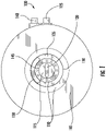
- an opaque top view of the base member 100 is shown with a first surface 105, gasket 110, a first base channel 120, a second base channel 130, an inner annular chamber 115, an outer annular chamber 135, a first side port 125, and a second side port 140.
- the first surface 105 of the base member 100 may be configured to abut the bottom surface of a platform member ( e.g. , bottom surface 500 in FIG. 5 ).
- the base member may define one or more annular walls. These annular walls may define one or more annular chambers. In the example embodiment shown in FIG.
- annular chamber 115 an inner annular chamber 115 and an outer annular chamber 135 are created by annular walls 145, 150 defined by the first surface 105 of the base member 100.
- one or more gaskets 110 may be disposed on the first surface 105 of the base member 100.
- the base member 100 may further define one or more channels to deliver a fluid from an external source coupled with one or more side ports 125, 140 to the respective inner annular chamber 115 or outer annular chamber 135, or to remove fluid from the inner annular chamber 115 or outer annular chamber 135 via a respective one or more side ports 125, 140.
- the base member 100 shown in FIG. 1 defines a first base channel 120 and a second base channel 130. As shown in FIG. 1 , these channels may be located between a top surface ( e.g. , first surface 105) and a bottom surface ( e.g. , bottom surface 200 shown in FIG. 1 ) of the base member 100.
- the base member 100 may be a solid body such that the first base channel 120 and the second base channel 130 are enclosed in and formed by the body of the base member 100.
- the channels 120, 130 may be formed in or on the base member 100 or may include one or more separately-attached conduits. These channels may be configured such that a fluid may travel therethrough.
- the base member 100 may be integrated into a larger table or work surface such that the top surface of the base member is part of the larger table or work surface.
- the base member 100 may define one or more side ports (e.g. , first side port 125 and second side port 140).
- the first base channel 120 may be in fluid communication with a first side port 125.
- this first side port 125 may be supplied with a fluid, such as an anesthetic or other treatment agent, that flows from the first side port 125 through the first base channel 120.
- the second base channel 130 may be in fluid communication with a second side port 140.
- a reverse flow e.g. , vacuum or other suction
- the second base channel 130 may receive the fluid (e.g. , anesthetic or other treatment agent) from the second side port 140, while the first base channel 120 receives the reverse flow.
- both of the channels 120, 130 may receive the fluid or reverse flow, either simultaneously or alternately, as required.
- a bottom view of the base member 100 is depicted showing a second, bottom surface 200 and the respective channels 120, 130 therein.
- the first base channel 120 may be positioned so as to connect the first side port 125 and the inner annular chamber 115.
- the second base channel 130 may be positioned so as to connect the second side port 140 and the outer annular chamber 135.
- excess material may be removed from the base member 100, such as shown in FIG. 2 , to reduce weight and cost of manufacturing (e.g. , partially hollowed out).
- the base member 100 may be a solid member such that the first channel 120 and the second base channel 130 are disposed between the first surface 105 and the second surface 200 of the base member 100 (i.e., located between the top and bottom of the base member). In some embodiments, excess material may be removed from the base member 100, such as shown in FIG. 2 , to reduce weight and cost of manufacturing.
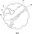
- FIG. 3 a top view of the base member 100 of FIG. 1 is illustrated with the channels 120, 130.
- the first surface 105 of the base member 100 clearly shows the arrangement of the first base channel 120 and the second base channel 130. These channels are shown terminating at the inner annular chamber 115 and the outer annular chamber 135, respectively.
- the gaskets 110 are shown atop the first surface 105.
- the gaskets 110 may be disposed on a top edge of the one or more annular walls 145, 150 and may be configured to encircle one or more annular walls defined by a platform member ( e.g. , annular walls 505, 510 of platform member 400 in FIG. 5 ).
- the gaskets 110 may be further configured to extend radially inward beyond their respective annular wall to prevent air leakage between chambers and channels.
- a gasket 110 disposed atop of outer annular wall 150 of the base member 100 may extend radially inward such that the gasket 110 contacts the outer annular wall 505 of the platform member 400, hereinafter described.
- the gasket 110 may substantially seal the outer annular chamber about a linear contact which encircles the outer annular wall 505.
- the gaskets 110 may further be configured to be recessed into the bottom surface of the base member 105 such that the gaskets 110 of the base member 100 do not contact the bottom surface 500 of the platform member 400 when the base member 100 and platform member 400 abut.
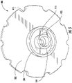
- a top view of a platform member 400 is illustrated installed on a base member 100.
- the depicted platform member 400 includes a top surface 405, a nozzle 410, one or more notches 415, and a nozzle channel 425.
- the platform 400 is configured to hold the specimen thereon and rotate relative to the base member 100.
- the platform 400 may rotate 360 degrees relative to the base member 100 in either direction ( e.g. , a clockwise and/or counter-clockwise rotation).
- the present disclosure contemplates that any number of full or partial rotations of the platform 400 may be made relative to the base member 100, in either direction.
- the nozzle 410 may supply a treatment agent to the specimen as discussed herein.
- the platform member may define one or more platform channels (e.g. , first platform channel 515 and second platform channel 520).
- the depicted platform member 400 includes a bottom surface 500, an inner annular wall 510, and outer annular wall 505, a first platform channel 515, a second platform channel 520, and one or more notches 415.
- at least a portion of the bottom surface 500 of the platform member 400 may be configured to abut the first surface 105 of the base member 100 during operation.
- the bottom surface 500 may define an inner annular wall 510 and an outer annular wall 505.
- the base member 100 may be configured to receive the platform member such that the inner annular wall 510 and the outer annular wall 505 nest in spaced defined by the one or more annular walls 145, 150 defined by the first surface 105 of the base member 100.
- the outer annular wall 150 of the base member 100 may encircle the outer annular wall 505 of the platform member 400.
- the inner annular wall 145 of the base member 100 may encircle the inner annular wall 510 of the platform member 400.
- connection between the platform member 400 and the base member 100 may be such that the inner annular chamber 115 is defined radially inward of the inner annular wall 510, and the outer annular chamber 135 is defined between the inner annular wall 510 and the outer annular wall 505.
- only one of the base member 100 and the platform member 400 may define annular walls and/or chambers.
- the base member 100 and/or the platform member 400 may be configured to receive one or more annular walls unattached to either member.
- one or more separate wall members may be placed between the platform member and base member to create one or more chambers.
- the present disclosure contemplates that any shape capable of creating a rotatable enclosure or chamber may be used.
- one end of the first platform channel 515 may terminate in the inner annular chamber 115 located in the space created radially inward of the inner annular wall 510.
- one end of the second platform channel 520 may terminate in the outer annular chamber 135 located in the space created between the inner annular wall 510 and the outer annular wall 505.
- the connection between the base member 100 and the platform member 400 may be such that the inner annular chamber 115 and the outer annular chamber 135 may be enclosed and may substantially airtight from one another.
- the connection between the base member 100 and the platform member 400 may be such that the first platform channel 515 and the first base channel 120 may be in continuous fluid communication.
- connection between the base member 100 and the platform member 400 may also be such that the second platform channel 520 and the second base channel 130 may be in continuous fluid communication.
- a fluid supplied to the first side port 125 may flow through the first base channel 120, into the inner annular chamber 115, and through the first platform channel 515.
- connection between the base member 100 and the platform member 400 may be such that the platform member 400 may rotate about the base member.
- the platform member 400 and base member 100 may allow unlimited rotation therebetween.
- the rotation of the platform member 400 about the base member 100 may maintain continuous fluid communication between the first base channel 120 and the first platform channel 515, as well as continuous fluid communication between the second base channel 130 and the second platform channel 520 for any rotational position of the platform member relative to the base member.
- one or more gaskets 110 may facilitate this connection between the base member 100 and the platform member 400 and help to prevent leakage of fluids supplied to the apparatus.
- the platform member 400 may define one or more notches 415 along the edge of the platform member 400 such as to facilitate user rotation of the platform member 400 about the base member 100.
- a bottom view of the platform member 400 is illustrated showing the platform channels 515, 520.
- the first platform channel 515 is shown terminating on one end radially inward of the inner annular wall 510 and the second platform member 520 is show terminating on one end between the inner annular wall 510 and the outer annular wall 505.
- the ends of the first platform channel 515 and the second platform channel 520 opposite the annular chambers may each terminate at the top surface 405 of the platform member 400.
- the one or more platform channels may be in fluid communication with a nozzle channel 425. As shown in FIGS.
- these channels may be located between a top surface 405 and a bottom surface 500 of the platform member 400.
- the platform member 400 may be solid such that the first platform channel 515 and the second platform channel 520 are enclosed in the body of the platform member 400.
- an example nozzle 410 is illustrated affixed atop the top surface 405 of the platform member 400.
- the nozzle 410 may include a nozzle channel 425, an inner shell 705, an outer shell 710, and a shell channel 715.
- the nozzle channel 425 may be in fluid communication with the first platform channel 515 and may extend through the outer shell 710 and inner shell 705, terminating within the inner shell 705 of the nozzle 410.
- a shell channel 715 may be defined by the space located between the inner shell 705 and the outer shell 710.
- the shell channel 715 may be in fluid communication with the second platform channel 520.
- the shell channel 715 may terminate about a peripheral edge of the nozzle 410, such that a semi-circular opening is defined between the inner shell 705 and the outer shell 710 as shown in FIG. 7 .
- an anesthetic may be administered to a subject using the nozzle channel 425, and a reverse flow (e.g., vacuum or other suction) may be applied to the shell channel 715 around the nozzle channel 425 to create a self-scavenging system whereby fluid is released within the nozzle 410 at an interior of the inner shell 705, and the fluid may be drawn into the shell channel 715 between the inner shell 705 and outer shell 710 at the peripheral edge.
- a reverse flow e.g., vacuum or other suction
- the specimen's head may be positioned in the nozzle 410 internal of the inner shell 705 to receive the fluid treatment agent.
- FIG. 7 illustrates the nozzle 410 affixed to the top surface 405 of the platform member 400, the present disclosure contemplates that the nozzle 410 may be located anywhere in proximity to the platform member so long as fluid communication between the nozzle channel 425 and the first platform channel 515 is maintained.
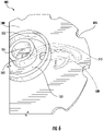
- FIGS. 8-9 cross-sectional views of the base member 100 and the platform member 400 are illustrated.
- the first base channel 120 is illustrated terminating in the first annular chamber 115 in the space radially inward of (bounded by) the inner annular wall 145 defined by the first surface 105 of the base member 100.
- the second base channel 130 is illustrated terminating in the outer annular chamber 135 in the space created between the inner annular wall 145 and the outer annular wall 150.
- Gaskets 110 are illustrated atop each of the inner annular wall 145 and the outer annular wall 150. In some embodiments, as previously described, the gaskets may extend radially inward beyond their respective annular wall to prevent air leakage between chambers and channels.
- FIG. 9 a cross-sectional view of the base member 100 and the platform member 400 are shown together.
- the first platform channel 515 is illustrated terminating on one end in the inner annular chamber 115 in the space radially inward of the inner annular wall 510.
- the first platform channel 515 is illustrated terminating on a second end at a position on the top surface 405 in fluid communication with a nozzle channel 425.
- the nozzle channel 425 may be in fluid communication with the first platform channel 515 and may extend through the outer shell 710 and inner shell 705, terminating within the inner shell 705 of the nozzle 410.
- the second platform channel 520 is illustrated terminating on one end in the outer annular chamber 135 in the space created between the inner annular wall 510 and the outer annular wall 505.
- the second platform channel 520 is illustrated terminating on a second end at a position on the top surface 405 in fluid communication with a shell channel 715.
- the shell channel 715 may be in fluid communication with the second platform channel 520 and may terminate about a peripheral edge of the nozzle 410, such that a semi-circular opening is defined between the inner shell 705 and the outer shell 710 as shown in FIG. 7 .
- a perspective view of a rotatable surgical table is displayed with the first surface 105 of base member 100 abutting the bottom surface of the platform member 400 ( e.g. , bottom surface 500 shown in FIG. 5 ).
- a user may rotate the platform member 400 relative to the base member 100 through use of the one or more notches 415.
- the rotatable surgical table may comprise a heated surface (e.g. , heated surface 1205 in FIG. 12 ) disposed on the top surface of the platform member ( e.g. , top surface 405 in FIG. 12 ).
- the electrical contacts 1100 may correspond to ends of a transmission medium (e.g. , wire, coil, or the like) disposed within the body of the platform member 400 and configured to transmit an electrical current.
- the base member 100 may also comprise a transmission medium configured to transmit an electrical current.
- the electrical contacts 1100 may be in electrical communication with the transmission medium of the base member when the bottom surface 500 platform member 400 abuts the first surface 105 of the base member 100. Electrical communication may further be maintained when the platform member 400 is rotated about the base member 100 via electric brushes, slip rings, rotary electrical interfaces, rotating electrical connectors, collectors, swivels, electrical rotary joints, rotary unions, or the like disposed between the platform member 400 and the base member 100.
- the platform member 400 and/or base member 100 may be configured to be in electrical communication with a power source (e.g. , battery, power outlet, or the like) such that an electrical current may be provided to the transmission medium.
- a power source e.g. , battery, power outlet, or the like
- the platform member 400 may further comprise a heated surface 1205.
- the heated surface 1205 may define a pad configured to receive a specimen.
- the heated surface 1205 may, via an electrical current supplied by the transmission medium associated with the electrical contacts 1100, generate heat (e.g. , via resistors or the like) such that the body temperature of the specimen may be influenced.
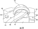
- the heated surface 1205 (as seen in FIG. 13 ) may extend into an area covered by the nozzle 410.
- the heated surface 1205 may cover any portion of the top surface 405 of the platform member 400, and/or that heat may be applied to any member or surface of any embodiment discussed herein.
- heat may be provided to the specimen from a variety of means (e.g. , chemical heat pad, heating lamp, or the like).
- the platform member 400 may further define one or more openings 1210 configured to receive one or more corresponding posts 1215.
- the one or more openings 1210 may be positioned at any location upon the top surface 405 of the platform member 400. Further, the one or more openings 1210 may be of any depth required to secure the location of an object disposed inside the one or more openings 1210 ( e.g. , post 1215). As seen in the enlarged area depicting post 1215, the one or more posts 1215 may be stepped ( e.g. , diameters of varying size) such that only a portion of the post 1215 may be disposed within the body of the platform member 400 when the post 1215 is received by an opening 1210.
- the posts 1215 may be configured such that a securing member (e.g. , string, elastic band, or the like) may wrap around the post and specimen in order to secure the specimen to the platform member 400.
- the posts 1215 may be positioned such that they form a boundary.
- the one or more posts 1215 may be disposed about the perimeter of the heated surface 1205 in order to limit or otherwise restrict the movement of a specimen disposed on the heated surface.
- the top surface 405 of the platform member 400 may comprise a rubberized surface at least partially covering the surface of the platform member 400.
- the rubberized surface may define a layer of an elastomer (e.g.
- the rubberized surface may also facilitate positioning of a specimen disposed thereon via the friction between the specimen and rubberized surface resisting the movement of the specimen during possible rotation of the platform member 400.
- the nozzle 410 may, comprise an inner shell 705, an outer shell 710, and a shell channel 715. Similar to the nozzle 410 in FIG. 7 , described above, the shell channel 715 may be defined by the space created between the outer shell 710 and inner shell 705, and may terminate about a peripheral edge of the nozzle 410. Additionally, the shell channel 715 may be in fluid communication with the second platform channel 520, and may be configured in some embodiments, in conjunction with a reverse flow (e.g. , vacuum suction) applied to the rotatable table (via side port 140 discussed above), to create a self-scavenging system.
- a reverse flow e.g. , vacuum suction
- the nozzle 410 may be configured without a nozzle channel 425 (as seen in FIG. 4 ) affixed to the top surface 405 of the platform member 400.
- the nozzle 410 may be configured such that the first platform channel 515 terminates at a point disposed on the top surface 405 of the platform member 400.
- the nozzle 410 may further be configured to cover the first platform channel 515 in order to direct the fluid flow supplied by the first platform channel 515.
- an alternative platform member may be provided that is comprised of two separable members, a top platform member 1400 and a bottom platform member 1500.
- the top platform member 1400 may define a first top platform opening 1410, a second top platform opening 1405, a bottom surface 1420, a recessed surface 1425, and a first keying feature 1415.
- the top platform member 1400 may also be configured to receive a bottom platform member ( e.g. , bottom platform member 1500 in FIG. 15 ).
- the top platform member may define a recess configured to receive the bottom platform member 1500 such that the top surface of the bottom platform member ( e.g. , top surface 1505 in FIG.
- the thickness of the top platform member i.e. , the difference between the surface to which the specimen is secured and the recessed surface 1425
- the thickness of the top platform member may be between 1-3 mm.
- the top platform member 1400 may be configured such that the first top platform opening 1410 is in fluid communication with the first platform channel 515. Additionally, the top platform member 100 may be configured such that the second top platform opening 1405 is in fluid communication with the second platform channel 520. In some embodiments, as above, the first top platform opening 1410 may be configured to administer an anesthetic to a rodent via a nozzle disposed on the top surface of the top platform member 1400 ( e.g. , nozzle 410). Additionally, as above, the second top platform opening 1405 may be in fluid communication with the second platform channel 520 and configured to provide a reverse suction (e.g. a vacuum suction).
- a reverse suction e.g. a vacuum suction
- This communication may create a self-scavenging system via a channel in fluid communication with the second top platform opening 1405 disposed about the peripheral edge of a nozzle disposed on the top surface of the top platform member ( e.g. , shell channel 715 in FIG. 12 ).
- the top platform member 1400 may further define a bottom surface 1420 configured to abut a top surface of a base member ( e.g. , first surface 105 of the base member 100 in FIG. 1 ).
- a bottom platform member 1500 is illustrated with a top surface 1505, a bottom surface 1510, a first platform channel 515, a second platform channel 520, a heated surface 1205, electrical elements 1520, and second keying feature 1515.
- the bottom platform member 1500 may be configured to be received by the top platform member 1400.
- the bottom platform member 1500 may nest within the top platform member 1400 such that the top surface 1505 abuts the recessed surface 1425.
- the bottom surface 1510 of the bottom platform member 1500 may be substantially level with the bottom surface 1420 of the top platform member 1400 such that both the bottom surfaces 1420, 1510 abut the top surface of a base member, when the separable platform member (e.g. , bottom platform member 1500 and top platform member 1400) is received by the base member ( e.g. , base member 100 in FIG. 1 ).
- the bottom platform member 1500 may comprise a heated surface 1205.
- the heated surface 1205 may, via an electrical current supplied by the transmission medium associated with the electrical contacts electrical elements 1520, generate heat (e.g. , via resistors or the like) such that the body temperature of a specimen affixed to a top surface of the top platform member 1400 may be influenced.
- the heated surface 1205 may heat (e.g. , via conduction, convection, or the like) the top platform member 1400.
- the heated surface 1205 may cover any portion of the top surface 1505 of the bottom platform member 1500, and/or that heat may be applied to any member or surface of any embodiment discussed herein.
- heat may be provided to a specimen from a variety of means (e.g. , chemical heat pad, heating lamp, or the like).
- the top surface 1505 may further comprise electrical elements 1520.
- the electrical elements 1520 may correspond to a transmission medium (e.g. , wire, coil, or the like) disposed within the body of the bottom platform member 1500 and configured to transmit an electrical current.
- a base member e.g. , base member 100 in FIG. 1
- the electrical elements 1520 may further include electrical contacts (e.g. , electrical contacts 1100 in FIG. 11 ) disposed on the bottom surface 1510 of the bottom platform member 1500.
- the electrical elements 1520 may be in electrical communication with a transmission medium of the base member when the bottom surface 1510 bottom platform member 1500 abuts the first surface 105 of the base member 100. Electrical communication may further be maintained when the separable platform member (e.g. , bottom platform member 1500 and top platform member 1400) is rotated about a base member via electric brushes, slip rings, rotary electrical interfaces, rotating electrical connectors, collectors, swivels, electrical rotary joints, rotary unions, or the like disposed between the separable platform member and the base member.
- the bottom platform member 1500 and/or base member may be configured to be in electrical communication with a power source (e.g. , battery, power outlet, or the like) such that an electrical current may be provided to the transmission medium.
- a power source e.g. , battery, power outlet, or the like
- the top platform member 1400 and the bottom platform member 1500 may further define a first keying element 1415 and a second keying element 1515, respectively.
- These keying elements may be configured such that the top platform member 1400 may only receive the bottom platform member 1500 in a defined orientation.
- the first keying element 1415 may define a 9-sided polygon and the second keying element 1515 may define a corresponding 9-side polygon.
- the keying elements may be configured to assist the top platform member 1400 receiving the bottom platform member 1500 in an orientation such that the first top platform opening 1410 and second top platform opening 1405 may be in fluid communication with the first platform channel 515 and second platform channel 520, respectively.
- first keying element 1415 and the second keying element 1515 may define any number of shapes without limitation.
- the first keying element 1415 and second keying element 1515 may each define corresponding unique shapes such that the top platform member 1400 may only receive the bottom platform member 1500 in an orientation in which fluid communication is maintained between the bottom platform member 1500 and the top platform member 1400.
- the unique shapes, defined by the keying elements may function to prevent any incorrect meshing between the platform members and prevent leakage of any gas traveling therein.
- the top platform member 1400 may be created from any suitable autoclavable material known in the art (e.g. , polypropylene, stainless steel, or the like).
- the top platform member 1400 may be comprised of a polypropylene plastic such that the top platform member ( i.e. , the surface contacting the specimen) may be removed following a procedure, and sterilized via an autoclave procedure.
- the bottom platform member 1500 may be created from a soft rubber material to facilitate rotation of the bottom platform member 1500 relative to a base member.
- the rotatable surgical table, systems, and exemplary methods described herein may be used to process (e.g., treat, operate on, dissect, etc.) a specimen (e.g. , a rat or other rodent or small animal), however, the exemplary methods and use of the tables and systems do not form part of the present invention.
- a specimen may be affixed to the top surface 405 of the platform member 400.
- the first side port 125 of the base member 100 may be supplied with an anesthetic or other treatment agent.
- This first side port 125 may be connected to a supply (e.g. , storage tank) via one or more connectors ( e.g. , medical tubes) that engage the first side port.
- the first side port 125 may be in fluid communication with the first base channel 120, located in the base member 100, such that the anesthetic flows from the anesthetic supply, through the connector and into the first base channel 120 via the first side port 125.
- the base member 100 may be configured to receive and/or otherwise connect with the rotatable platform member 400.
- At least one of the base member 100 and the base member 400 may define one or more annular walls.
- the connection between the base member 100 and the platform member 400 may be such that the platform member 400 abuts ( e.g. , rests atop) the base member 100.
- the annular walls 505 510 of the platform member 400 nest within the base member 100.
- connection between the base member and the platform member further defines an inner annular chamber 115 and an outer annular chamber 135.
- the inner annular chamber 115 may be in fluid communication with the first base channel 120.
- the platform member 400 may further define a first platform channel 515 in fluid communication with the inner annular chamber 115, and in fluid communication with the first base channel 120. Therefore, the treatment agent may flow from the first base channel 120 through the first platform channel 515 via the inner annular chamber 115.
- the first platform channel 515 may terminate at a position on the top surface 405 of the platform member. Further, this first platform channel 515 may be in fluid communication with a nozzle channel 425. This nozzle channel 425 may receive the treatment agent (e.g. , a gaseous anesthetic) flowing from the first platform channel 515 and dispose of the anesthetic to a specimen via the nozzle 410.
- the treatment agent e.g. , a gaseous anesthetic
- the second side port 140 of the base member 100 may be supplied with a reverse flow (e.g. , vacuum or other suction).
- This second side port 140 may be connected to a supply (e.g. , storage tank) via one or more connectors ( e . g ., medical tubes).
- the second side port 140 may be in fluid communication with the second base channel 130, located in or attached to the base member 100, such that a reverse flow removes fluid from the second base channel 130 via the second side port 140.
- the base member 100 may be configured to receive and/or otherwise connect with the platform member 400 and may define one or more annular walls.
- connection between the base member and the platform member defines an outer annular chamber 135.
- the outer annular chamber 135 may be in fluid communication with the second base channel 130.
- the platform member 400 may further define a second platform channel 520 in fluid communication with the outer annular chamber 135, and inherently in fluid communication with the second base channel 130. Therefore, the reverse flow may draw fluid from the second platform channel 520 to the second base channel 130 via the outer annular chamber 135 and out the side port 140.
- the second platform channel 520 may terminate at a position on the top surface 405 of the platform member. Further, this second platform channel 520 may be in fluid communication with a shell channel 715 between the inner shell 705 and the outer shell 710.
- This shell channel 715 may be disposed around the edge of the nozzle 410 and may be in fluid communication with the second platform channel 520. Accordingly, a reverse flow may be applied to the shell channel 715 via the second platform channel 520.
- the reverse flow or suction applied at the shell channel 715 around the nozzle 410 and nozzle channel 425 may create a self-scavenging system.
- the self-scavenging system may be reversed, such that the treatment agent is released from the shell channel 715 and excess agent is drawn into the nozzle channel 425 by the reverse flow.
- the example method of processing a specimen using the rotatable surgical table includes supplying an anesthetic via the first side port 125 through the first base channel 120, the inner annular chamber 115, the first platform channel 515, and the nozzle channel 425, and is administered to the specimen.
- a reverse flow e.g. , a pump or suction
- the above described connection between the platform member 400 and the base member 100 is configured to allow the platform member 400 to be rotated about the base member 100 while maintaining continuous fluid communication between the above described channels at any angle and for any number of rotations.
- the annular chambers may be arranged concentrically, such that each annular chamber is positioned a predetermined radial distance from the rotational center of the platform/base interface. Such an arrangement may facilitate the unlimited rotational connectivity of the embodiments described herein.
- One or more gaskets may be located between the base member 100 and platform member 400 to facilitate maintaining fluid communication and prevent air leakage at the interface between the platform 400 and the base 100.
- the platform member 400 may be notched ( e.g. , notches 415) to assist the user is effectuating the rotation of the platform member 400 about the base member 100.
- the present disclosure contemplates that the present invention may be created from any suitable material known in the art (e.g. , plastic, resin, ceramic, metal, rubber, or the like). By way of example, the present invention may be created through 3-D printing, injection molding, among others without limitation. Additionally, due to the oft required sterile nature of medical environments, the present disclosure contemplates that the present invention may be comprised of bacterial resistant materials or subjected to any manner of sterilization procedure or device ( e.g. , an autoclave). Although the present invention is depicted as two members ( e.g. , a base member and a platform member with an attached nozzle), the present disclosure contemplates that the present invention may be comprised of any number of individual members or pieces so long as continuous fluid communication is maintained between the respective channels.
- any suitable material known in the art e.g. , plastic, resin, ceramic, metal, rubber, or the like.
- the present invention may be created through 3-D printing, injection molding, among others without limitation.
- the present disclosure contemplate
- a treatment agent is provided through one or more of the channels to the nozzle.
- the treatment agent may be an anesthetic, such as, for example, vaporized isoflurane.
- the base member and platform member shown and described herein each include two channels, which in some embodiments may respectively supply a treatment agent and apply a reverse flow to the nozzle.
- only one channel may be provided that supplies a treatment agent or applies a reverse flow.
- three or more channels may be provided to apply multiple treatment agents, multiple reverse flows, or combinations thereof.
- three or more annular chambers may be likewise arranged in concentric positions in a similar manner to the embodiments shown in FIGS. 1-7 .
Description
- Surgical tables and associated systems for examining and operating on specimens, which may include rodents and other small animals, provide support and stability for performing delicate procedures. Surgical procedures are often paired with anesthesia as a means to reduce the pain of the subject as well ensure stability throughout the procedure by reducing the movement of the subject.
- Traditionally, a subject or specimen was secured to a stationary object and administered anesthesia through a separate source such as by injectable or inhalable means. Additionally, once secured, the specimen could only be moved through contact with the specimen. This current process of adjusting a specimen is cumbersome and inefficient providing slower procedure times and increased costs. Conventional surgical apparatuses and associated methods also fail to allow for easy access to the specimen from various angles during a procedure.
- Applicant has identified a number of additional deficiencies and problems associated with conventional surgical tables and associated systems and methods. Through applied effort, ingenuity, and innovation, many of these identified problems have been solved by developing solutions that are included in embodiments of the present invention, many examples of which are described in detail herein.
-
US 2009/126113 A1 discloses a surgical table for infants and small animals that has a bed assembly that is rotatable. The bed assembly includes a stationary plate and a rotating plate with a brake that controls rotation. The bed assembly may be connected by a clamp to the frame of a conventional operating table and supported alongside or above. The bed assembly may also be permanently mounted on its own vertical support. The bed assembly may also be permanently mounted to the operating table by an articulated clamp that allows the bed assembly to be stored alongside. A central opening is present in both plates so that hoses and wires connected to the patient will pass through this opening to permit rotation of the patient with the table with no stress on the hoses or wires where they connect to the patient. -
US 809 358 A discloses a veterinary surgeons table. -
US 2014/069426 A1 discloses a method comprising positioning a nose of a rodent within a nose chamber of a device for anesthetizing the rodent, the nose chamber configured to partially enclose an anesthetizing gas and hold the nose of the rodent in contact with the anesthetizing gas, delivering a positive flow of the anesthetizing gas into the nose chamber through a gas intake channel sufficient to anesthetize the rodent, supplying a waste gas reservoir to collect the anesthetizing gas, the waste gas reservoir in communication with the nose chamber through a gas transport channel and coupled with the nose chamber in an open configuration allowing the anesthetizing gas and ambient air to flow into the waste gas reservoir, and actively retrieving the anesthetizing gas and ambient air from the waste gas reservoir with a negative flow conveyed through a gas outtake channel in communication with the waste gas reservoir. -
CN 102 755 202 B discloses an animal operation and experiment table. The animal operation and experiment table comprises a table top of an experiment table, rails and an operation table, wherein the table top of the experiment table is provided with a first imaging hole which passes through the table top of the experiment table; the rails are arranged on the table top of the experiment table so as to fix an imaging device; the operation table is movably arranged on the table top of the experiment table and is provided with a second imaging hole which passes through the operation table; and the first image hole and the second imaging hole are kept coaxial. - According to the present invention there is provided a surgical table as specified by independent claim 1, with preferred embodiments disclosed by the dependent claims.
- The apparatus and exemplary methods described herein provide a rotatable surgical table capable of supplying an anesthetic to a specimen wherein the flow of anesthesia is maintained when the table is rotated.
- Having thus described the invention in general terms, reference will now be made to the accompanying drawings, which are not necessarily drawn to scale, and wherein:
-
FIG. 1 illustrates a top view of a base member of a surgical apparatus, in accordance with some embodiments discussed herein; -
FIG. 2 illustrates a bottom view of the base member ofFIG. 1 ; -
FIG. 3 illustrates a top view of the base member ofFIG 1 ; -
FIG. 4 illustrates a top view of a platform member of a surgical apparatus, in accordance with some embodiments discussed herein; -
FIG. 5 illustrates a bottom view of the platform member ofFIG. 4 ; -
FIG. 6 illustrates a bottom view of the platform member ofFIG. 4 ; -
FIG. 7 illustrates a nozzle, in accordance with some embodiments discussed herein; -
FIG. 8 illustrates a cross-sectional side view of the base member ofFIG. 1 ; -
FIG. 9 illustrates a cross-sectional side view of the platform and base members ofFIGS. 1 and4 ; -
FIG. 10 illustrates the rotatable surgical table, in accordance with some embodiments discussed herein; -
FIG. 11 illustrates a bottom view of an alternative platform member, in accordance with some embodiments discussed herein; -
FIG. 12 illustrates a top view of a platform member ofFIG. 11 in conjunction with a base member; -
FIG. 13 illustrates a nozzle, in accordance with some embodiments discussed herein; -
FIG. 14 illustrates a bottom view of a top portion of an alternative platform member, in accordance with some embodiments discussed herein; and -
FIG. 15 illustrates a perspective view of a bottom portion of an alternative platform member, in accordance with some embodiments discussed herein. - Embodiments of the present invention now will be described more fully hereinafter with reference to the accompanying drawings, in which some, but not all embodiments of the invention are shown. Indeed, the invention may be embodied in many different forms and should not be construed as limited to the embodiments set forth herein; rather, these embodiments are provided so that this disclosure will satisfy applicable legal requirements.
- The scope of the invention is defined by the appended claims.
- Like reference numerals refer to like elements throughout.
- In the development of new medical procedures, medications, and other treatment options, rodents (i.e., rats, mice, etc.) are often utilized as a medium for verifying the safety and effectiveness of new developments before administration to human subjects. Rodents are often utilized for their convenience and their genetic similarity to humans. As mammals, rodents share similar biological processes and systems to their human counterparts and, therefore, are an effective indicator as to the likelihood of success associated with a proposed medical procedure.
- In many surgical environments, a surgical table or apparatus is utilized to support and secure the subject during a procedure. A surgical table may secure a specimen at a desired position and may limit motion of the specimen to ensure that the procedure is completed properly. Additionally, anesthesia is also often utilized to ensure that the specimen remains in a desired position. Traditionally, a separate anesthetic supply device (e.g., free standing) is utilized to deliver an anesthetic to the specimen resulting in various tubes and cords freely hanging to connect the anesthetic supply device to the specimen. In these circumstances, navigation around the specimen during operation is tedious and creates the risk of disturbing the specimen. Additionally, repositioning of the specimen during a procedure, using conventional technologies, requires releasing the specimen from the surgical table and/or moving the physician about the surgical table.
- Embodiments of the present invention that are described hereinbelow provide a rotatable surgical table for processing a specimen. In addition, embodiments of the present invention also provide for supplying an anesthetic to the specimen via the surgical table, as opposed to a separate device, such that the specimen may receive continuous anesthetic during rotation of the surgical table. In addition to rodents and small animals, one of ordinary skill in the art will appreciate that the devices and exemplary methods discussed herein may be scaled to accommodate any patient or specimen.
- For the sake of clarity and convenience of description, the embodiments that are described herein are made in reference to various components, elements, members, or the like that allow and/or maintain fluid communication. As used herein, the term "fluid" may refer to a substance, such as a liquid or gas, which does not have a fixed shape and is capable of flowing. By way of example, in some embodiments described below, a gaseous anesthetic may be considered a fluid, and may be administered to a specimen via various respective channels in fluid communication with one another (e.g., an anesthetic supplied to a first base channel in fluid communication with a first platform channel).
- Some embodiments described herein include a base member and platform member. The base member and the platform member may abut one another and be configured such that the platform member may rotate relative to the base member. The platform member and base member may each define one or more channels where the one or more channels of the platform member are in fluid communication with the one or more channels of the base member. In some embodiments, the platform member and the base member may each define two channels. In such an embodiment, a treatment agent (e.g., an anesthetic) may be supplied to a first channel of the base member that is in fluid communication with a first channel of the platform member. In some embodiments, a nozzle (such as, for example, a nose cone) may be affixed to the top surface of the platform member such that a specimen (e.g., a mouse of other rodent) secured to the platform may be administered an anesthetic. This nozzle may be in fluid communication with the first channel of the platform member. As described in further detail below, some embodiments of the rotatable surgical table may utilize the second channels of both the platform member and the base member in conjunction with a reverse flow (e.g., vacuum suction) to create a self-scavenging system at the nozzle.
- With reference to
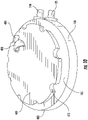
FIG. 1 , an opaque top view of thebase member 100 is shown with afirst surface 105,gasket 110, afirst base channel 120, asecond base channel 130, an innerannular chamber 115, an outerannular chamber 135, afirst side port 125, and asecond side port 140. Thefirst surface 105 of thebase member 100 may be configured to abut the bottom surface of a platform member (e.g.,bottom surface 500 inFIG. 5 ). In some embodiments, the base member may define one or more annular walls. These annular walls may define one or more annular chambers. In the example embodiment shown inFIG. 1 , an innerannular chamber 115 and an outerannular chamber 135 are created byannular walls first surface 105 of thebase member 100. In order to promote sealing of the annular chambers and base channels from the environment, one ormore gaskets 110 may be disposed on thefirst surface 105 of thebase member 100. - The
base member 100 may further define one or more channels to deliver a fluid from an external source coupled with one ormore side ports annular chamber 115 or outerannular chamber 135, or to remove fluid from the innerannular chamber 115 or outerannular chamber 135 via a respective one ormore side ports base member 100 shown inFIG. 1 defines afirst base channel 120 and asecond base channel 130. As shown inFIG. 1 , these channels may be located between a top surface (e.g., first surface 105) and a bottom surface (e.g.,bottom surface 200 shown inFIG. 1 ) of thebase member 100. Thebase member 100 may be a solid body such that thefirst base channel 120 and thesecond base channel 130 are enclosed in and formed by the body of thebase member 100. In some embodiments, thechannels base member 100 or may include one or more separately-attached conduits. These channels may be configured such that a fluid may travel therethrough. In some embodiments, thebase member 100 may be integrated into a larger table or work surface such that the top surface of the base member is part of the larger table or work surface. - In some embodiments, the
base member 100 may define one or more side ports (e.g.,first side port 125 and second side port 140). Thefirst base channel 120 may be in fluid communication with afirst side port 125. In some embodiments, thisfirst side port 125 may be supplied with a fluid, such as an anesthetic or other treatment agent, that flows from thefirst side port 125 through thefirst base channel 120. Thesecond base channel 130 may be in fluid communication with asecond side port 140. In some embodiments, a reverse flow (e.g., vacuum or other suction) may be applied to thesecond side port 140 such that a fluid may travel through thesecond base channel 130. In some embodiments, thesecond base channel 130 may receive the fluid (e.g., anesthetic or other treatment agent) from thesecond side port 140, while thefirst base channel 120 receives the reverse flow. In some other embodiments, both of thechannels - With reference to
FIG. 2 , a bottom view of thebase member 100 is depicted showing a second,bottom surface 200 and therespective channels FIG. 2 , thefirst base channel 120 may be positioned so as to connect thefirst side port 125 and the innerannular chamber 115. Similarly, thesecond base channel 130 may be positioned so as to connect thesecond side port 140 and the outerannular chamber 135. As shown inFIG. 2 , in some embodiments, excess material may be removed from thebase member 100, such as shown inFIG. 2 , to reduce weight and cost of manufacturing (e.g., partially hollowed out). As discussed above, in some embodiments, thebase member 100 may be a solid member such that thefirst channel 120 and thesecond base channel 130 are disposed between thefirst surface 105 and thesecond surface 200 of the base member 100 (i.e., located between the top and bottom of the base member). In some embodiments, excess material may be removed from thebase member 100, such as shown inFIG. 2 , to reduce weight and cost of manufacturing. - With reference to
FIG. 3 , a top view of thebase member 100 ofFIG. 1 is illustrated with thechannels first surface 105 of thebase member 100 clearly shows the arrangement of thefirst base channel 120 and thesecond base channel 130. These channels are shown terminating at the innerannular chamber 115 and the outerannular chamber 135, respectively. In addition, thegaskets 110 are shown atop thefirst surface 105. Thegaskets 110 may be disposed on a top edge of the one or moreannular walls annular walls platform member 400 inFIG. 5 ). Thegaskets 110 may be further configured to extend radially inward beyond their respective annular wall to prevent air leakage between chambers and channels. For example, agasket 110 disposed atop of outerannular wall 150 of thebase member 100 may extend radially inward such that thegasket 110 contacts the outerannular wall 505 of theplatform member 400, hereinafter described. In such an example, thegasket 110 may substantially seal the outer annular chamber about a linear contact which encircles the outerannular wall 505. Thegaskets 110 may further be configured to be recessed into the bottom surface of thebase member 105 such that thegaskets 110 of thebase member 100 do not contact thebottom surface 500 of theplatform member 400 when thebase member 100 andplatform member 400 abut. - With reference to
FIG. 4 , a top view of aplatform member 400 is illustrated installed on abase member 100. The depictedplatform member 400 includes atop surface 405, anozzle 410, one ormore notches 415, and anozzle channel 425. Theplatform 400 is configured to hold the specimen thereon and rotate relative to thebase member 100. By way of example, theplatform 400 may rotate 360 degrees relative to thebase member 100 in either direction (e.g., a clockwise and/or counter-clockwise rotation). Further, the present disclosure contemplates that any number of full or partial rotations of theplatform 400 may be made relative to thebase member 100, in either direction. Thenozzle 410 may supply a treatment agent to the specimen as discussed herein. As described in greater detail below, with regards toFIG. 6 , the platform member may define one or more platform channels (e.g.,first platform channel 515 and second platform channel 520). - Similarly, with reference to
FIG. 5 , a bottom view of an embodiment of theplatform member 400 is illustrated. The depictedplatform member 400 includes abottom surface 500, an innerannular wall 510, and outerannular wall 505, afirst platform channel 515, asecond platform channel 520, and one ormore notches 415. In some embodiments, at least a portion of thebottom surface 500 of theplatform member 400 may be configured to abut thefirst surface 105 of thebase member 100 during operation. In some embodiments, thebottom surface 500 may define an innerannular wall 510 and an outerannular wall 505. Thebase member 100 may be configured to receive the platform member such that the innerannular wall 510 and the outerannular wall 505 nest in spaced defined by the one or moreannular walls first surface 105 of thebase member 100. By way of example, when thefirst surface 105 of thebase member 100 abuts thebottom surface 500 of theplatform member 400, the outerannular wall 150 of thebase member 100 may encircle the outerannular wall 505 of theplatform member 400. Likewise, in such an example, the innerannular wall 145 of thebase member 100 may encircle the innerannular wall 510 of theplatform member 400. Further, in such an embodiment, the connection between theplatform member 400 and thebase member 100 may be such that the innerannular chamber 115 is defined radially inward of the innerannular wall 510, and the outerannular chamber 135 is defined between the innerannular wall 510 and the outerannular wall 505. - In some embodiments, only one of the
base member 100 and theplatform member 400 may define annular walls and/or chambers. In other embodiments, thebase member 100 and/or theplatform member 400 may be configured to receive one or more annular walls unattached to either member. For example, one or more separate wall members may be placed between the platform member and base member to create one or more chambers. Additionally, although shown as circular or annular walls, the present disclosure contemplates that any shape capable of creating a rotatable enclosure or chamber may be used. - With further reference to
FIG. 5 , one end of thefirst platform channel 515 may terminate in the innerannular chamber 115 located in the space created radially inward of the innerannular wall 510. Similarly, one end of thesecond platform channel 520 may terminate in the outerannular chamber 135 located in the space created between the innerannular wall 510 and the outerannular wall 505. The connection between thebase member 100 and theplatform member 400 may be such that the innerannular chamber 115 and the outerannular chamber 135 may be enclosed and may substantially airtight from one another. The connection between thebase member 100 and theplatform member 400 may be such that thefirst platform channel 515 and thefirst base channel 120 may be in continuous fluid communication. Similarly, the connection between thebase member 100 and theplatform member 400 may also be such that thesecond platform channel 520 and thesecond base channel 130 may be in continuous fluid communication. By way of example, a fluid supplied to thefirst side port 125 may flow through thefirst base channel 120, into the innerannular chamber 115, and through thefirst platform channel 515. - In some embodiments, the connection between the
base member 100 and theplatform member 400 may be such that theplatform member 400 may rotate about the base member. In some embodiments, theplatform member 400 andbase member 100 may allow unlimited rotation therebetween. The rotation of theplatform member 400 about thebase member 100 may maintain continuous fluid communication between thefirst base channel 120 and thefirst platform channel 515, as well as continuous fluid communication between thesecond base channel 130 and thesecond platform channel 520 for any rotational position of the platform member relative to the base member. As discussed above, one ormore gaskets 110 may facilitate this connection between thebase member 100 and theplatform member 400 and help to prevent leakage of fluids supplied to the apparatus. Additionally, theplatform member 400 may define one ormore notches 415 along the edge of theplatform member 400 such as to facilitate user rotation of theplatform member 400 about thebase member 100. - With reference to
FIG. 6 , a bottom view of theplatform member 400 is illustrated showing theplatform channels first platform channel 515 is shown terminating on one end radially inward of the innerannular wall 510 and thesecond platform member 520 is show terminating on one end between the innerannular wall 510 and the outerannular wall 505. The ends of thefirst platform channel 515 and thesecond platform channel 520 opposite the annular chambers may each terminate at thetop surface 405 of theplatform member 400. As shown inFIG. 4 , in some embodiments, the one or more platform channels may be in fluid communication with anozzle channel 425. As shown inFIGS. 5-6 , these channels may be located between atop surface 405 and abottom surface 500 of theplatform member 400. In some embodiments, theplatform member 400 may be solid such that thefirst platform channel 515 and thesecond platform channel 520 are enclosed in the body of theplatform member 400. - With reference to
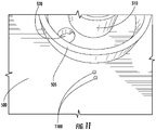
FIG. 7 , anexample nozzle 410 is illustrated affixed atop thetop surface 405 of theplatform member 400. Thenozzle 410 may include anozzle channel 425, aninner shell 705, anouter shell 710, and ashell channel 715. In the example embodiment shown inFIG. 7 , thenozzle channel 425 may be in fluid communication with thefirst platform channel 515 and may extend through theouter shell 710 andinner shell 705, terminating within theinner shell 705 of thenozzle 410. Additionally, ashell channel 715 may be defined by the space located between theinner shell 705 and theouter shell 710. In some still further embodiments, theshell channel 715 may be in fluid communication with thesecond platform channel 520. Theshell channel 715 may terminate about a peripheral edge of thenozzle 410, such that a semi-circular opening is defined between theinner shell 705 and theouter shell 710 as shown inFIG. 7 . In some embodiments, an anesthetic may be administered to a subject using thenozzle channel 425, and a reverse flow (e.g., vacuum or other suction) may be applied to theshell channel 715 around thenozzle channel 425 to create a self-scavenging system whereby fluid is released within thenozzle 410 at an interior of theinner shell 705, and the fluid may be drawn into theshell channel 715 between theinner shell 705 andouter shell 710 at the peripheral edge. The specimen's head may be positioned in thenozzle 410 internal of theinner shell 705 to receive the fluid treatment agent. Although the example embodiment ofFIG. 7 illustrates thenozzle 410 affixed to thetop surface 405 of theplatform member 400, the present disclosure contemplates that thenozzle 410 may be located anywhere in proximity to the platform member so long as fluid communication between thenozzle channel 425 and thefirst platform channel 515 is maintained. - With reference to
FIGS. 8-9 , cross-sectional views of thebase member 100 and theplatform member 400 are illustrated. InFIG. 8 , thefirst base channel 120 is illustrated terminating in the firstannular chamber 115 in the space radially inward of (bounded by) the innerannular wall 145 defined by thefirst surface 105 of thebase member 100. Thesecond base channel 130 is illustrated terminating in the outerannular chamber 135 in the space created between the innerannular wall 145 and the outerannular wall 150.Gaskets 110 are illustrated atop each of the innerannular wall 145 and the outerannular wall 150. In some embodiments, as previously described, the gaskets may extend radially inward beyond their respective annular wall to prevent air leakage between chambers and channels. - With reference to
FIG. 9 , a cross-sectional view of thebase member 100 and theplatform member 400 are shown together. InFIG. 9 , thefirst platform channel 515 is illustrated terminating on one end in the innerannular chamber 115 in the space radially inward of the innerannular wall 510. Thefirst platform channel 515 is illustrated terminating on a second end at a position on thetop surface 405 in fluid communication with anozzle channel 425. As discussed above, thenozzle channel 425 may be in fluid communication with thefirst platform channel 515 and may extend through theouter shell 710 andinner shell 705, terminating within theinner shell 705 of thenozzle 410. Thesecond platform channel 520 is illustrated terminating on one end in the outerannular chamber 135 in the space created between the innerannular wall 510 and the outerannular wall 505. Thesecond platform channel 520 is illustrated terminating on a second end at a position on thetop surface 405 in fluid communication with ashell channel 715. As discussed above, theshell channel 715 may be in fluid communication with thesecond platform channel 520 and may terminate about a peripheral edge of thenozzle 410, such that a semi-circular opening is defined between theinner shell 705 and theouter shell 710 as shown inFIG. 7 . - With reference to
FIG. 10 , a perspective view of a rotatable surgical table is displayed with thefirst surface 105 ofbase member 100 abutting the bottom surface of the platform member 400 (e.g.,bottom surface 500 shown inFIG. 5 ). As discussed further below, a user may rotate theplatform member 400 relative to thebase member 100 through use of the one ormore notches 415. - With reference to
FIG. 11 , a bottom view of analternative platform member 400 is displayed. InFIG. 11 , two electrical contacts 1100 are illustrated disposed on thebottom surface 500 of theplatform member 400. In some embodiments, the rotatable surgical table may comprise a heated surface (e.g.,heated surface 1205 inFIG. 12 ) disposed on the top surface of the platform member (e.g.,top surface 405 inFIG. 12 ). The electrical contacts 1100 may correspond to ends of a transmission medium (e.g., wire, coil, or the like) disposed within the body of theplatform member 400 and configured to transmit an electrical current. In some embodiments, thebase member 100 may also comprise a transmission medium configured to transmit an electrical current. In such an embodiment, the electrical contacts 1100 may be in electrical communication with the transmission medium of the base member when thebottom surface 500platform member 400 abuts thefirst surface 105 of thebase member 100. Electrical communication may further be maintained when theplatform member 400 is rotated about thebase member 100 via electric brushes, slip rings, rotary electrical interfaces, rotating electrical connectors, collectors, swivels, electrical rotary joints, rotary unions, or the like disposed between theplatform member 400 and thebase member 100. In some embodiments, theplatform member 400 and/orbase member 100 may be configured to be in electrical communication with a power source (e.g., battery, power outlet, or the like) such that an electrical current may be provided to the transmission medium. - With reference to
FIG. 12 , a top view of analternative platform member 400 is illustrated in conjunction with a base member (e.g.,base member 100 ofFIG. 1 ). In some embodiments, theplatform member 400 may further comprise aheated surface 1205. As described above, theheated surface 1205 may define a pad configured to receive a specimen. Theheated surface 1205 may, via an electrical current supplied by the transmission medium associated with the electrical contacts 1100, generate heat (e.g., via resistors or the like) such that the body temperature of the specimen may be influenced. In some embodiments, the heated surface 1205 (as seen inFIG. 13 ) may extend into an area covered by thenozzle 410. The present disclosure contemplates that theheated surface 1205 may cover any portion of thetop surface 405 of theplatform member 400, and/or that heat may be applied to any member or surface of any embodiment discussed herein. Although described in conjunction with an electrically powered heating pad, the present disclosure contemplates that heat may be provided to the specimen from a variety of means (e.g., chemical heat pad, heating lamp, or the like). - With continued reference to
FIG. 12 , theplatform member 400 may further define one ormore openings 1210 configured to receive one or morecorresponding posts 1215. The one ormore openings 1210 may be positioned at any location upon thetop surface 405 of theplatform member 400. Further, the one ormore openings 1210 may be of any depth required to secure the location of an object disposed inside the one or more openings 1210 (e.g., post 1215). As seen in the enlarged area depicting post 1215, the one ormore posts 1215 may be stepped (e.g., diameters of varying size) such that only a portion of thepost 1215 may be disposed within the body of theplatform member 400 when thepost 1215 is received by anopening 1210. - In some embodiments, the
posts 1215 may be configured such that a securing member (e.g., string, elastic band, or the like) may wrap around the post and specimen in order to secure the specimen to theplatform member 400. In some other embodiments, theposts 1215 may be positioned such that they form a boundary. By way of example, the one ormore posts 1215 may be disposed about the perimeter of theheated surface 1205 in order to limit or otherwise restrict the movement of a specimen disposed on the heated surface. In some still further embodiments, thetop surface 405 of theplatform member 400 may comprise a rubberized surface at least partially covering the surface of theplatform member 400. By way of example, the rubberized surface may define a layer of an elastomer (e.g., rubber or the like) of 3mm-4mm in thickness such that a specimen disposed on the rubberized surface may be pinned to the rubberized surface. Additionally, the rubberized surface may also facilitate positioning of a specimen disposed thereon via the friction between the specimen and rubberized surface resisting the movement of the specimen during possible rotation of theplatform member 400. - With reference to
FIGS. 12-13 , an alternative nozzle 410 (e.g., nose cone) for use in some embodiments is illustrated. Thenozzle 410, with reference toFIG. 13 , may, comprise aninner shell 705, anouter shell 710, and ashell channel 715. Similar to thenozzle 410 inFIG. 7 , described above, theshell channel 715 may be defined by the space created between theouter shell 710 andinner shell 705, and may terminate about a peripheral edge of thenozzle 410. Additionally, theshell channel 715 may be in fluid communication with thesecond platform channel 520, and may be configured in some embodiments, in conjunction with a reverse flow (e.g., vacuum suction) applied to the rotatable table (viaside port 140 discussed above), to create a self-scavenging system. - Additionally, in some embodiments as seen in
FIG. 13 , thenozzle 410 may be configured without a nozzle channel 425 (as seen inFIG. 4 ) affixed to thetop surface 405 of theplatform member 400. In such an embodiment, thenozzle 410 may be configured such that thefirst platform channel 515 terminates at a point disposed on thetop surface 405 of theplatform member 400. Thenozzle 410 may further be configured to cover thefirst platform channel 515 in order to direct the fluid flow supplied by thefirst platform channel 515. - With reference to
FIGS. 14-15 , in some embodiments, an alternative platform member may be provided that is comprised of two separable members, atop platform member 1400 and abottom platform member 1500. As seen inFIG. 14 , thetop platform member 1400 may define a firsttop platform opening 1410, a secondtop platform opening 1405, abottom surface 1420, a recessedsurface 1425, and afirst keying feature 1415. Thetop platform member 1400 may also be configured to receive a bottom platform member (e.g.,bottom platform member 1500 inFIG. 15 ). By way of example, the top platform member may define a recess configured to receive thebottom platform member 1500 such that the top surface of the bottom platform member (e.g.,top surface 1505 inFIG. 15 ) abuts the recessedsurface 1425 of thetop platform member 1400. In some embodiments, the thickness of the top platform member (i.e., the difference between the surface to which the specimen is secured and the recessed surface 1425) may be between 1-3 mm. - In some embodiments, the
top platform member 1400 may be configured such that the firsttop platform opening 1410 is in fluid communication with thefirst platform channel 515. Additionally, thetop platform member 100 may be configured such that the secondtop platform opening 1405 is in fluid communication with thesecond platform channel 520. In some embodiments, as above, the firsttop platform opening 1410 may be configured to administer an anesthetic to a rodent via a nozzle disposed on the top surface of the top platform member 1400 (e.g., nozzle 410). Additionally, as above, the secondtop platform opening 1405 may be in fluid communication with thesecond platform channel 520 and configured to provide a reverse suction (e.g. a vacuum suction). This communication may create a self-scavenging system via a channel in fluid communication with the secondtop platform opening 1405 disposed about the peripheral edge of a nozzle disposed on the top surface of the top platform member (e.g.,shell channel 715 inFIG. 12 ). Thetop platform member 1400 may further define abottom surface 1420 configured to abut a top surface of a base member (e.g.,first surface 105 of thebase member 100 inFIG. 1 ). - With reference to
FIG. 15 , abottom platform member 1500 is illustrated with atop surface 1505, abottom surface 1510, afirst platform channel 515, asecond platform channel 520, aheated surface 1205,electrical elements 1520, andsecond keying feature 1515. As discussed with reference toFIG. 14 , thebottom platform member 1500 may be configured to be received by thetop platform member 1400. By way of example, thebottom platform member 1500 may nest within thetop platform member 1400 such that thetop surface 1505 abuts the recessedsurface 1425. In such an example, thebottom surface 1510 of thebottom platform member 1500 may be substantially level with thebottom surface 1420 of thetop platform member 1400 such that both thebottom surfaces bottom platform member 1500 and top platform member 1400) is received by the base member (e.g.,base member 100 inFIG. 1 ). - With continued reference to
FIG. 15 , in some embodiments, thebottom platform member 1500 may comprise aheated surface 1205. Theheated surface 1205 may, via an electrical current supplied by the transmission medium associated with the electrical contactselectrical elements 1520, generate heat (e.g., via resistors or the like) such that the body temperature of a specimen affixed to a top surface of thetop platform member 1400 may be influenced. By way of example, when thebottom platform member 1500 is received by thetop platform member 1400, theheated surface 1205 may heat (e.g., via conduction, convection, or the like) thetop platform member 1400. The present disclosure contemplates that theheated surface 1205 may cover any portion of thetop surface 1505 of thebottom platform member 1500, and/or that heat may be applied to any member or surface of any embodiment discussed herein. As above, although described in conjunction with an electrically powered heating pad, the present disclosure contemplates that heat may be provided to a specimen from a variety of means (e.g., chemical heat pad, heating lamp, or the like). - In some embodiments, the
top surface 1505 may further compriseelectrical elements 1520. Theelectrical elements 1520 may correspond to a transmission medium (e.g., wire, coil, or the like) disposed within the body of thebottom platform member 1500 and configured to transmit an electrical current. As above, in some embodiments, a base member (e.g.,base member 100 inFIG. 1 ) may also comprise a transmission medium configured to transmit an electrical current. In such an embodiment, theelectrical elements 1520 may further include electrical contacts (e.g., electrical contacts 1100 inFIG. 11 ) disposed on thebottom surface 1510 of thebottom platform member 1500. Theelectrical elements 1520 may be in electrical communication with a transmission medium of the base member when thebottom surface 1510bottom platform member 1500 abuts thefirst surface 105 of thebase member 100. Electrical communication may further be maintained when the separable platform member (e.g.,bottom platform member 1500 and top platform member 1400) is rotated about a base member via electric brushes, slip rings, rotary electrical interfaces, rotating electrical connectors, collectors, swivels, electrical rotary joints, rotary unions, or the like disposed between the separable platform member and the base member. In some embodiments, thebottom platform member 1500 and/or base member may be configured to be in electrical communication with a power source (e.g., battery, power outlet, or the like) such that an electrical current may be provided to the transmission medium. - With continued reference to
FIGS. 14-15 , thetop platform member 1400 and thebottom platform member 1500 may further define afirst keying element 1415 and asecond keying element 1515, respectively. These keying elements may be configured such that thetop platform member 1400 may only receive thebottom platform member 1500 in a defined orientation. By way of example, thefirst keying element 1415 may define a 9-sided polygon and thesecond keying element 1515 may define a corresponding 9-side polygon. In such an example, the keying elements may be configured to assist thetop platform member 1400 receiving thebottom platform member 1500 in an orientation such that the firsttop platform opening 1410 and secondtop platform opening 1405 may be in fluid communication with thefirst platform channel 515 andsecond platform channel 520, respectively. Although illustrated inFIGS. 14-15 as a 9-side polygon, the present disclosure contemplates that thefirst keying element 1415 and thesecond keying element 1515 may define any number of shapes without limitation. In some embodiments, thefirst keying element 1415 andsecond keying element 1515 may each define corresponding unique shapes such that thetop platform member 1400 may only receive thebottom platform member 1500 in an orientation in which fluid communication is maintained between thebottom platform member 1500 and thetop platform member 1400. In such an embodiment, the unique shapes, defined by the keying elements, may function to prevent any incorrect meshing between the platform members and prevent leakage of any gas traveling therein. - The present disclosure also contemplates that the
top platform member 1400 may be created from any suitable autoclavable material known in the art (e.g., polypropylene, stainless steel, or the like). By way of example, thetop platform member 1400 may be comprised of a polypropylene plastic such that the top platform member (i.e., the surface contacting the specimen) may be removed following a procedure, and sterilized via an autoclave procedure. The present disclosure further contemplates that thebottom platform member 1500 may be created from a soft rubber material to facilitate rotation of thebottom platform member 1500 relative to a base member. - As will be appreciated by the description above, the rotatable surgical table, systems, and exemplary methods described herein may be used to process (e.g., treat, operate on, dissect, etc.) a specimen (e.g., a rat or other rodent or small animal), however, the exemplary methods and use of the tables and systems do not form part of the present invention.
- In an example embodiment shown in
FIGS. 1-7 , a specimen may be affixed to thetop surface 405 of theplatform member 400. Thefirst side port 125 of thebase member 100 may be supplied with an anesthetic or other treatment agent. Thisfirst side port 125 may be connected to a supply (e.g., storage tank) via one or more connectors (e.g., medical tubes) that engage the first side port. Thefirst side port 125 may be in fluid communication with thefirst base channel 120, located in thebase member 100, such that the anesthetic flows from the anesthetic supply, through the connector and into thefirst base channel 120 via thefirst side port 125. Thebase member 100 may be configured to receive and/or otherwise connect with therotatable platform member 400. At least one of thebase member 100 and thebase member 400 may define one or more annular walls. The connection between thebase member 100 and theplatform member 400 may be such that theplatform member 400 abuts (e.g., rests atop) thebase member 100. In the example embodiment, theannular walls 505 510 of theplatform member 400 nest within thebase member 100. - In the example embodiment, the connection between the base member and the platform member further defines an inner
annular chamber 115 and an outerannular chamber 135. The innerannular chamber 115 may be in fluid communication with thefirst base channel 120. Theplatform member 400 may further define afirst platform channel 515 in fluid communication with the innerannular chamber 115, and in fluid communication with thefirst base channel 120. Therefore, the treatment agent may flow from thefirst base channel 120 through thefirst platform channel 515 via the innerannular chamber 115. In the example embodiment, thefirst platform channel 515 may terminate at a position on thetop surface 405 of the platform member. Further, thisfirst platform channel 515 may be in fluid communication with anozzle channel 425. Thisnozzle channel 425 may receive the treatment agent (e.g., a gaseous anesthetic) flowing from thefirst platform channel 515 and dispose of the anesthetic to a specimen via thenozzle 410. - Similarly, the
second side port 140 of thebase member 100 may be supplied with a reverse flow (e.g., vacuum or other suction). Thissecond side port 140 may be connected to a supply (e.g., storage tank) via one or more connectors (e.g., medical tubes). Thesecond side port 140 may be in fluid communication with thesecond base channel 130, located in or attached to thebase member 100, such that a reverse flow removes fluid from thesecond base channel 130 via thesecond side port 140. As discussed above, thebase member 100 may be configured to receive and/or otherwise connect with theplatform member 400 and may define one or more annular walls. - In the example embodiment, the connection between the base member and the platform member defines an outer
annular chamber 135. The outerannular chamber 135 may be in fluid communication with thesecond base channel 130. Theplatform member 400 may further define asecond platform channel 520 in fluid communication with the outerannular chamber 135, and inherently in fluid communication with thesecond base channel 130. Therefore, the reverse flow may draw fluid from thesecond platform channel 520 to thesecond base channel 130 via the outerannular chamber 135 and out theside port 140. In the example embodiment, thesecond platform channel 520 may terminate at a position on thetop surface 405 of the platform member. Further, thissecond platform channel 520 may be in fluid communication with ashell channel 715 between theinner shell 705 and theouter shell 710. Thisshell channel 715 may be disposed around the edge of thenozzle 410 and may be in fluid communication with thesecond platform channel 520. Accordingly, a reverse flow may be applied to theshell channel 715 via thesecond platform channel 520. The reverse flow or suction applied at theshell channel 715 around thenozzle 410 andnozzle channel 425 may create a self-scavenging system. As would be appreciated by one of ordinary skill in the art in light of the present disclosure, the self-scavenging system may be reversed, such that the treatment agent is released from theshell channel 715 and excess agent is drawn into thenozzle channel 425 by the reverse flow. - The example method of processing a specimen using the rotatable surgical table includes supplying an anesthetic via the
first side port 125 through thefirst base channel 120, the innerannular chamber 115, thefirst platform channel 515, and thenozzle channel 425, and is administered to the specimen. A reverse flow (e.g., a pump or suction) may be applied to thesecond side port 140 such that the air or fluid located about theshell channel 715 enters theshell channel 715, flows through thesecond platform channel 520, the outerannular chamber 135, thesecond base channel 130, and to a reverse flow supply (e.g., a pump) via thesecond side port 140. - Additionally, during processing of a specimen, the above described connection between the
platform member 400 and thebase member 100 is configured to allow theplatform member 400 to be rotated about thebase member 100 while maintaining continuous fluid communication between the above described channels at any angle and for any number of rotations. The annular chambers may be arranged concentrically, such that each annular chamber is positioned a predetermined radial distance from the rotational center of the platform/base interface. Such an arrangement may facilitate the unlimited rotational connectivity of the embodiments described herein. One or more gaskets may be located between thebase member 100 andplatform member 400 to facilitate maintaining fluid communication and prevent air leakage at the interface between theplatform 400 and thebase 100. Further, theplatform member 400 may be notched (e.g., notches 415) to assist the user is effectuating the rotation of theplatform member 400 about thebase member 100. - The present disclosure contemplates that the present invention may be created from any suitable material known in the art (e.g., plastic, resin, ceramic, metal, rubber, or the like). By way of example, the present invention may be created through 3-D printing, injection molding, among others without limitation. Additionally, due to the oft required sterile nature of medical environments, the present disclosure contemplates that the present invention may be comprised of bacterial resistant materials or subjected to any manner of sterilization procedure or device (e.g., an autoclave). Although the present invention is depicted as two members (e.g., a base member and a platform member with an attached nozzle), the present disclosure contemplates that the present invention may be comprised of any number of individual members or pieces so long as continuous fluid communication is maintained between the respective channels.
- In embodiments discussed herein, a treatment agent is provided through one or more of the channels to the nozzle. In some embodiments, the treatment agent may be an anesthetic, such as, for example, vaporized isoflurane.
- Many modifications and other embodiments of the inventions set forth herein will come to mind to one skilled in the art to which these inventions pertain having the benefit of the teachings presented in the foregoing descriptions and the associated drawings. For example, the base member and platform member shown and described herein each include two channels, which in some embodiments may respectively supply a treatment agent and apply a reverse flow to the nozzle. In some embodiments, only one channel may be provided that supplies a treatment agent or applies a reverse flow. In some other embodiments, three or more channels may be provided to apply multiple treatment agents, multiple reverse flows, or combinations thereof. In instances having three or more channels, three or more annular chambers may be likewise arranged in concentric positions in a similar manner to the embodiments shown in
FIGS. 1-7 . Although the figures only show certain components of the apparatus, systems, and associated methods described herein, it is understood that various other components may also be part of the rotatable surgical table. In addition, the methods described above may include fewer steps in some cases, while in other cases may include additional steps. - Although specific terms are employed herein, they are used in a generic and descriptive sense only and not for purposes of limitation.
- The scope of the invention is defined by the appended claims.
Claims (8)
- A surgical table comprising:a base member (100) defining:a first surface (105), andat least one base channel (120, 130);a platform member (400) defining:
a top surface (405) and a bottom surface (500), wherein the bottom surface (500) is configured to abut the first surface (105) of the base member (100),
wherein the platform member (400) defines at least one platform channel (515, 520), wherein the at least one platform channel (515, 520) and the at least one base channel (120, 130) are in fluid communication, wherein the platform member (400) is configured to rotate relative to the base member (100) while maintaining said fluid communication; anda nozzle (410) disposed on the top surface (405) on the platform member (400), wherein the nozzle (410) is in fluid communication with the at least one platform channel (515, 520). - The surgical table according to claim 1, wherein the at least one base channel (120, 130) comprises, a first base channel (120) and a second base channel (130), and, wherein the at least one platform channel (515, 520) comprises a first platform channel (515) and a second platform channel (520)
wherein the nozzle (410) optionally defines an inner shell (705) in continuous fluid communication with the first platform channel (515) and an outer shell (710) in fluid communication with the second platform channel (520) creating a self-scavenging system. - The surgical table according to claim 1, wherein at least one of the base member (100) and the platform member (400) is configured to connect the at least one base channel (120, 130) with the at least one platform channel (515, 520).
- The surgical table according to claim 1, further comprising one or more walls disposed between the first surface (105) of the base member (100) and the bottom surface (500) of the platform member (400), wherein the one or more walls are configured to maintain fluid communication between the at least one channel (120, 130) of the base member (100) and the at least one channel (515, 520) of the platform member (400).
- The surgical table according to claim 1, wherein at least one of the bottom surface (500) of the platform member (400) and the first surface (105) of the base member (100) define two concentric annular walls (145, 150, 505, 510);
optionally wherein one or more gaskets (110) are optionally disposed between the first surface (105) of the base member (100) and the bottom surface (500) of the platform member (400) and the one or more gaskets (110) abut the two concentric annular walls (145, 150, 505, 510). - The surgical table according to claim 1, wherein the base member (100) and the platform member (400) define a first annular chamber (115) bounded by an innermost wall of the concentric annular walls (145, 510) and a second annular chamber (135) disposed between the two concentric annular walls (145, 150, 505, 510) such that a first channel (515) of the platform member (400) and a first channel (120) of the base member (130) are configured to be in continuous fluid communication and a second channel (130) of the base member (100) and the second channel (520) of the platform member (400) are configured to be in continuous fluid communication.
- The surgical table according to claim 1, wherein one or more gaskets (110) are disposed between the first surface (105) of the base member (100) and the bottom surface (500) of the platform member (400).
- The surgical table according to claim 1, wherein the base member (100) further defines one or more side ports (125, 140) configured to create a fluid connection between an input source and the at least one base channel (120, 130).
Applications Claiming Priority (2)
| Application Number | Priority Date | Filing Date | Title |
|---|---|---|---|
| US201762448710P | 2017-01-20 | 2017-01-20 | |
| PCT/US2018/014325 WO2018136681A1 (en) | 2017-01-20 | 2018-01-19 | Rotatable surgical table |
Publications (2)
| Publication Number | Publication Date |
|---|---|
| EP3570775A1 EP3570775A1 (en) | 2019-11-27 |
| EP3570775B1 true EP3570775B1 (en) | 2022-04-13 |
Family
ID=61764109
Family Applications (1)
| Application Number | Title | Priority Date | Filing Date |
|---|---|---|---|
| EP18713057.0A Active EP3570775B1 (en) | 2017-01-20 | 2018-01-19 | Rotatable surgical table |
Country Status (9)
| Country | Link |
|---|---|
| US (2) | US10758331B2 (en) |
| EP (1) | EP3570775B1 (en) |
| JP (1) | JP6867497B2 (en) |
| KR (1) | KR102297172B1 (en) |
| CN (1) | CN110366397B (en) |
| AU (1) | AU2018210253B2 (en) |
| CA (1) | CA3049138A1 (en) |
| ES (1) | ES2913217T3 (en) |
| WO (1) | WO2018136681A1 (en) |
Families Citing this family (3)
| Publication number | Priority date | Publication date | Assignee | Title |
|---|---|---|---|---|
| CA3049138A1 (en) | 2017-01-20 | 2018-07-26 | Regeneron Pharmaceuticals, Inc. | Rotatable surgical table |
| FR3096573A1 (en) * | 2019-05-31 | 2020-12-04 | Francisco Félix SOUBRIER PEDRENO | Mobilization device for animals |
| CN113041067B (en) * | 2021-03-19 | 2022-07-08 | 四川大学华西医院 | Totally enclosed formula neurosurgery operation equipment |
Family Cites Families (23)
| Publication number | Priority date | Publication date | Assignee | Title |
|---|---|---|---|---|
| US809358A (en) | 1905-02-01 | 1906-01-09 | Leonard L Conkey | Veterinary surgeon's table. |
| US3318597A (en) | 1964-11-09 | 1967-05-09 | Briggs Jamalabo Abel | Dissecting board and head clamp |
| US3548840A (en) | 1967-10-30 | 1970-12-22 | Gallaher Ltd | Cigarette smoking machines |
| US3687137A (en) * | 1969-11-13 | 1972-08-29 | Donald W Johnson | Small animal anesthesia machine |
| US4332244A (en) | 1980-10-08 | 1982-06-01 | The Government Of The United States As Represented By The Secretary Of Department Of Health And Human Services | Mask for the safe delivery of inhalation gases to small laboratory animals |
| SE8008962L (en) | 1980-12-18 | 1982-06-19 | Erik Allan Lindkvist | DEVICE FOR ANCESTIC MASK |
| US4807617A (en) | 1988-02-01 | 1989-02-28 | Massachusetts Eye And Ear Infirmary | Scavenging mask |
| US5297502A (en) * | 1993-05-05 | 1994-03-29 | Jaeger Rudolf J | Modular reversible-flow-past nasopulmonary respiratory dosing system for laboratory animals |
| US6776158B1 (en) * | 2001-07-26 | 2004-08-17 | Euthanex Corporation | System for anesthetizing laboratory animals |
| US8905585B2 (en) * | 2004-05-13 | 2014-12-09 | Or21, Llc | Operating room/intervention room |
| US7996348B2 (en) | 2006-12-08 | 2011-08-09 | Pandya Ashish A | 100GBPS security and search architecture using programmable intelligent search memory (PRISM) that comprises one or more bit interval counters |
| US7992238B2 (en) * | 2007-09-13 | 2011-08-09 | Thomas Hejkal | Rotatable surgery table |
| HUE059796T2 (en) | 2009-03-19 | 2022-12-28 | Univ Johns Hopkins | Psma-targeting compounds and uses thereof |
| US20130213318A1 (en) | 2010-07-09 | 2013-08-22 | Petedge, Inc. | Animal Handling Station |
| KR101280350B1 (en) * | 2011-04-27 | 2013-07-01 | 조순복 | Small animal operation table for veterinary medicine |
| CN102755202B (en) * | 2012-08-02 | 2015-01-07 | 上海交通大学 | Animal operation and experiment table |
| US20140069426A1 (en) | 2012-09-13 | 2014-03-13 | James Thornton Houts | Systems and methods for anesthetizing a rodent |
| CN203315265U (en) | 2013-07-09 | 2013-12-04 | 南阳医学高等专科学校第一附属医院 | Overturn-type anesthesia surgery table facet |
| US9751888B2 (en) | 2013-10-04 | 2017-09-05 | Infinity Pharmaceuticals, Inc. | Heterocyclic compounds and uses thereof |
| KR101491344B1 (en) | 2013-11-07 | 2015-02-11 | 울산대학교 산학협력단 | Operating table for animals of small size |
| SI3161128T1 (en) | 2014-06-26 | 2019-02-28 | Regeneron Pharmaceuticals, Inc. | Methods and compositions for targeted genetic modifications and methods of use |
| WO2016007524A1 (en) | 2014-07-07 | 2016-01-14 | Jackson Roger P | Single and dual column patient positioning and support structure |
| CA3049138A1 (en) | 2017-01-20 | 2018-07-26 | Regeneron Pharmaceuticals, Inc. | Rotatable surgical table |
-
2018
- 2018-01-19 CA CA3049138A patent/CA3049138A1/en active Pending
- 2018-01-19 WO PCT/US2018/014325 patent/WO2018136681A1/en unknown
- 2018-01-19 ES ES18713057T patent/ES2913217T3/en active Active
- 2018-01-19 EP EP18713057.0A patent/EP3570775B1/en active Active
- 2018-01-19 JP JP2019538640A patent/JP6867497B2/en active Active
- 2018-01-19 AU AU2018210253A patent/AU2018210253B2/en active Active
- 2018-01-19 US US15/875,716 patent/US10758331B2/en active Active
- 2018-01-19 CN CN201880007757.XA patent/CN110366397B/en active Active
- 2018-01-19 KR KR1020197023462A patent/KR102297172B1/en active IP Right Grant
-
2020
- 2020-07-23 US US16/936,831 patent/US11864976B2/en active Active
Non-Patent Citations (1)
| Title |
|---|
| None * |
Also Published As
| Publication number | Publication date |
|---|---|
| AU2018210253A1 (en) | 2019-07-18 |
| US20200352691A1 (en) | 2020-11-12 |
| JP2020505121A (en) | 2020-02-20 |
| CN110366397B (en) | 2021-10-29 |
| AU2018210253B2 (en) | 2023-05-04 |
| US10758331B2 (en) | 2020-09-01 |
| CN110366397A (en) | 2019-10-22 |
| KR20190113826A (en) | 2019-10-08 |
| US20180206962A1 (en) | 2018-07-26 |
| US11864976B2 (en) | 2024-01-09 |
| KR102297172B1 (en) | 2021-09-03 |
| ES2913217T3 (en) | 2022-06-01 |
| EP3570775A1 (en) | 2019-11-27 |
| CA3049138A1 (en) | 2018-07-26 |
| JP6867497B2 (en) | 2021-04-28 |
| WO2018136681A1 (en) | 2018-07-26 |
Similar Documents
| Publication | Publication Date | Title |
|---|---|---|
| US11864976B2 (en) | Rotatable surgical table | |
| US8858418B2 (en) | Method and apparatus for providing treatment in a warming device | |
| CA2420427C (en) | Respiratory care multiple access port assembly and adapter | |
| ES2236758T3 (en) | APPLIANCE FOR MANAGING A TOXIC FLUID. | |
| JP4387105B2 (en) | Infusion hub assembly and fluid line cutting system | |
| US20140378821A1 (en) | Mask for analyzed mammals | |
| WO2016137838A1 (en) | Handheld surgical endoscope | |
| JPH05507004A (en) | Devices and methods for collecting breathing gases | |
| JP2018531670A (en) | Dual port tube for aspiration and nutrient supply systems, methods, and devices | |
| US20170312066A1 (en) | Versatile inhalation anesthesia platform for small animal surgery | |
| CN109568774B (en) | A device of dosing is intervene in environmental protection for treating liver cancer | |
| CN219127961U (en) | Nasal cavity administration device | |
| CN209173140U (en) | A kind of Severe acute disease oxygen supply drug delivery device | |
| CN1424009A (en) | Steam anionic fumigating instrument | |
| CN117338588A (en) | Traditional chinese medicine fumigation therapeutic instrument for department of rheumatism immunity | |
| JPH0246279Y2 (en) | ||
| CN108324568A (en) | Syringe Adapter | |
| CN102525775B (en) | Infant care system and device | |
| US20170312156A1 (en) | Patient transfer device and associated systems and methods |
Legal Events
| Date | Code | Title | Description |
|---|---|---|---|
| STAA | Information on the status of an ep patent application or granted ep patent |
Free format text: STATUS: UNKNOWN |
|
| STAA | Information on the status of an ep patent application or granted ep patent |
Free format text: STATUS: THE INTERNATIONAL PUBLICATION HAS BEEN MADE |
|
| PUAI | Public reference made under article 153(3) epc to a published international application that has entered the european phase |
Free format text: ORIGINAL CODE: 0009012 |
|
| STAA | Information on the status of an ep patent application or granted ep patent |
Free format text: STATUS: REQUEST FOR EXAMINATION WAS MADE |
|
| 17P | Request for examination filed |
Effective date: 20190719 |
|
| AK | Designated contracting states |
Kind code of ref document: A1 Designated state(s): AL AT BE BG CH CY CZ DE DK EE ES FI FR GB GR HR HU IE IS IT LI LT LU LV MC MK MT NL NO PL PT RO RS SE SI SK SM TR |
|
| AX | Request for extension of the european patent |
Extension state: BA ME |
|
| DAV | Request for validation of the european patent (deleted) | ||
| DAX | Request for extension of the european patent (deleted) | ||
| REG | Reference to a national code |
Ref country code: HK Ref legal event code: DE Ref document number: 40017245 Country of ref document: HK |
|
| STAA | Information on the status of an ep patent application or granted ep patent |
Free format text: STATUS: EXAMINATION IS IN PROGRESS |
|
| STAA | Information on the status of an ep patent application or granted ep patent |
Free format text: STATUS: EXAMINATION IS IN PROGRESS |
|
| 17Q | First examination report despatched |
Effective date: 20201020 |
|
| GRAP | Despatch of communication of intention to grant a patent |
Free format text: ORIGINAL CODE: EPIDOSNIGR1 |
|
| STAA | Information on the status of an ep patent application or granted ep patent |
Free format text: STATUS: GRANT OF PATENT IS INTENDED |
|
| INTG | Intention to grant announced |
Effective date: 20211026 |
|
| GRAS | Grant fee paid |
Free format text: ORIGINAL CODE: EPIDOSNIGR3 |
|
| GRAA | (expected) grant |
Free format text: ORIGINAL CODE: 0009210 |
|
| STAA | Information on the status of an ep patent application or granted ep patent |
Free format text: STATUS: THE PATENT HAS BEEN GRANTED |
|
| AK | Designated contracting states |
Kind code of ref document: B1 Designated state(s): AL AT BE BG CH CY CZ DE DK EE ES FI FR GB GR HR HU IE IS IT LI LT LU LV MC MK MT NL NO PL PT RO RS SE SI SK SM TR |
|
| REG | Reference to a national code |
Ref country code: GB Ref legal event code: FG4D |
|
| REG | Reference to a national code |
Ref country code: CH Ref legal event code: EP |
|
| REG | Reference to a national code |
Ref country code: DE Ref legal event code: R096 Ref document number: 602018033737 Country of ref document: DE |
|
| REG | Reference to a national code |
Ref country code: IE Ref legal event code: FG4D |
|
| REG | Reference to a national code |
Ref country code: AT Ref legal event code: REF Ref document number: 1482811 Country of ref document: AT Kind code of ref document: T Effective date: 20220515 |
|
| REG | Reference to a national code |
Ref country code: NL Ref legal event code: FP Ref country code: ES Ref legal event code: FG2A Ref document number: 2913217 Country of ref document: ES Kind code of ref document: T3 Effective date: 20220601 |
|
| REG | Reference to a national code |
Ref country code: LT Ref legal event code: MG9D |
|
| REG | Reference to a national code |
Ref country code: AT Ref legal event code: MK05 Ref document number: 1482811 Country of ref document: AT Kind code of ref document: T Effective date: 20220413 |
|
| PG25 | Lapsed in a contracting state [announced via postgrant information from national office to epo] |
Ref country code: SE Free format text: LAPSE BECAUSE OF FAILURE TO SUBMIT A TRANSLATION OF THE DESCRIPTION OR TO PAY THE FEE WITHIN THE PRESCRIBED TIME-LIMIT Effective date: 20220413 Ref country code: PT Free format text: LAPSE BECAUSE OF FAILURE TO SUBMIT A TRANSLATION OF THE DESCRIPTION OR TO PAY THE FEE WITHIN THE PRESCRIBED TIME-LIMIT Effective date: 20220816 Ref country code: NO Free format text: LAPSE BECAUSE OF FAILURE TO SUBMIT A TRANSLATION OF THE DESCRIPTION OR TO PAY THE FEE WITHIN THE PRESCRIBED TIME-LIMIT Effective date: 20220713 Ref country code: LT Free format text: LAPSE BECAUSE OF FAILURE TO SUBMIT A TRANSLATION OF THE DESCRIPTION OR TO PAY THE FEE WITHIN THE PRESCRIBED TIME-LIMIT Effective date: 20220413 Ref country code: HR Free format text: LAPSE BECAUSE OF FAILURE TO SUBMIT A TRANSLATION OF THE DESCRIPTION OR TO PAY THE FEE WITHIN THE PRESCRIBED TIME-LIMIT Effective date: 20220413 Ref country code: GR Free format text: LAPSE BECAUSE OF FAILURE TO SUBMIT A TRANSLATION OF THE DESCRIPTION OR TO PAY THE FEE WITHIN THE PRESCRIBED TIME-LIMIT Effective date: 20220714 Ref country code: FI Free format text: LAPSE BECAUSE OF FAILURE TO SUBMIT A TRANSLATION OF THE DESCRIPTION OR TO PAY THE FEE WITHIN THE PRESCRIBED TIME-LIMIT Effective date: 20220413 Ref country code: BG Free format text: LAPSE BECAUSE OF FAILURE TO SUBMIT A TRANSLATION OF THE DESCRIPTION OR TO PAY THE FEE WITHIN THE PRESCRIBED TIME-LIMIT Effective date: 20220713 Ref country code: AT Free format text: LAPSE BECAUSE OF FAILURE TO SUBMIT A TRANSLATION OF THE DESCRIPTION OR TO PAY THE FEE WITHIN THE PRESCRIBED TIME-LIMIT Effective date: 20220413 |
|
| PG25 | Lapsed in a contracting state [announced via postgrant information from national office to epo] |
Ref country code: RS Free format text: LAPSE BECAUSE OF FAILURE TO SUBMIT A TRANSLATION OF THE DESCRIPTION OR TO PAY THE FEE WITHIN THE PRESCRIBED TIME-LIMIT Effective date: 20220413 Ref country code: PL Free format text: LAPSE BECAUSE OF FAILURE TO SUBMIT A TRANSLATION OF THE DESCRIPTION OR TO PAY THE FEE WITHIN THE PRESCRIBED TIME-LIMIT Effective date: 20220413 Ref country code: LV Free format text: LAPSE BECAUSE OF FAILURE TO SUBMIT A TRANSLATION OF THE DESCRIPTION OR TO PAY THE FEE WITHIN THE PRESCRIBED TIME-LIMIT Effective date: 20220413 Ref country code: IS Free format text: LAPSE BECAUSE OF FAILURE TO SUBMIT A TRANSLATION OF THE DESCRIPTION OR TO PAY THE FEE WITHIN THE PRESCRIBED TIME-LIMIT Effective date: 20220813 |
|
| REG | Reference to a national code |
Ref country code: DE Ref legal event code: R097 Ref document number: 602018033737 Country of ref document: DE |
|
| PG25 | Lapsed in a contracting state [announced via postgrant information from national office to epo] |
Ref country code: SM Free format text: LAPSE BECAUSE OF FAILURE TO SUBMIT A TRANSLATION OF THE DESCRIPTION OR TO PAY THE FEE WITHIN THE PRESCRIBED TIME-LIMIT Effective date: 20220413 Ref country code: SK Free format text: LAPSE BECAUSE OF FAILURE TO SUBMIT A TRANSLATION OF THE DESCRIPTION OR TO PAY THE FEE WITHIN THE PRESCRIBED TIME-LIMIT Effective date: 20220413 Ref country code: RO Free format text: LAPSE BECAUSE OF FAILURE TO SUBMIT A TRANSLATION OF THE DESCRIPTION OR TO PAY THE FEE WITHIN THE PRESCRIBED TIME-LIMIT Effective date: 20220413 Ref country code: EE Free format text: LAPSE BECAUSE OF FAILURE TO SUBMIT A TRANSLATION OF THE DESCRIPTION OR TO PAY THE FEE WITHIN THE PRESCRIBED TIME-LIMIT Effective date: 20220413 Ref country code: DK Free format text: LAPSE BECAUSE OF FAILURE TO SUBMIT A TRANSLATION OF THE DESCRIPTION OR TO PAY THE FEE WITHIN THE PRESCRIBED TIME-LIMIT Effective date: 20220413 Ref country code: CZ Free format text: LAPSE BECAUSE OF FAILURE TO SUBMIT A TRANSLATION OF THE DESCRIPTION OR TO PAY THE FEE WITHIN THE PRESCRIBED TIME-LIMIT Effective date: 20220413 |
|
| PLBE | No opposition filed within time limit |
Free format text: ORIGINAL CODE: 0009261 |
|
| STAA | Information on the status of an ep patent application or granted ep patent |
Free format text: STATUS: NO OPPOSITION FILED WITHIN TIME LIMIT |
|
| 26N | No opposition filed |
Effective date: 20230116 |
|
| PG25 | Lapsed in a contracting state [announced via postgrant information from national office to epo] |
Ref country code: AL Free format text: LAPSE BECAUSE OF FAILURE TO SUBMIT A TRANSLATION OF THE DESCRIPTION OR TO PAY THE FEE WITHIN THE PRESCRIBED TIME-LIMIT Effective date: 20220413 |
|
| PGFP | Annual fee paid to national office [announced via postgrant information from national office to epo] |
Ref country code: ES Payment date: 20230201 Year of fee payment: 6 Ref country code: CH Payment date: 20230201 Year of fee payment: 6 |
|
| PG25 | Lapsed in a contracting state [announced via postgrant information from national office to epo] |
Ref country code: SI Free format text: LAPSE BECAUSE OF FAILURE TO SUBMIT A TRANSLATION OF THE DESCRIPTION OR TO PAY THE FEE WITHIN THE PRESCRIBED TIME-LIMIT Effective date: 20220413 |
|
| PGFP | Annual fee paid to national office [announced via postgrant information from national office to epo] |
Ref country code: IT Payment date: 20230103 Year of fee payment: 6 Ref country code: DE Payment date: 20221220 Year of fee payment: 6 |
|
| P01 | Opt-out of the competence of the unified patent court (upc) registered |
Effective date: 20230404 |
|
| PG25 | Lapsed in a contracting state [announced via postgrant information from national office to epo] |
Ref country code: LU Free format text: LAPSE BECAUSE OF NON-PAYMENT OF DUE FEES Effective date: 20230119 |
|
| REG | Reference to a national code |
Ref country code: BE Ref legal event code: MM Effective date: 20230131 |
|
| PG25 | Lapsed in a contracting state [announced via postgrant information from national office to epo] |
Ref country code: BE Free format text: LAPSE BECAUSE OF NON-PAYMENT OF DUE FEES Effective date: 20230131 |
|
| PGFP | Annual fee paid to national office [announced via postgrant information from national office to epo] |
Ref country code: GB Payment date: 20231219 Year of fee payment: 7 |
|
| PGFP | Annual fee paid to national office [announced via postgrant information from national office to epo] |
Ref country code: NL Payment date: 20231219 Year of fee payment: 7 Ref country code: IE Payment date: 20231221 Year of fee payment: 7 Ref country code: FR Payment date: 20231219 Year of fee payment: 7 |
|
| PGFP | Annual fee paid to national office [announced via postgrant information from national office to epo] |
Ref country code: ES Payment date: 20240202 Year of fee payment: 7 |