EP3570533A1 - Bildverarbeitungsvorrichtung, steuerungsverfahren, programm und aufzeichnungsmedium - Google Patents
Bildverarbeitungsvorrichtung, steuerungsverfahren, programm und aufzeichnungsmedium Download PDFInfo
- Publication number
- EP3570533A1 EP3570533A1 EP19178138.4A EP19178138A EP3570533A1 EP 3570533 A1 EP3570533 A1 EP 3570533A1 EP 19178138 A EP19178138 A EP 19178138A EP 3570533 A1 EP3570533 A1 EP 3570533A1
- Authority
- EP
- European Patent Office
- Prior art keywords
- display
- image
- reconstruction
- subject distance
- subject
- Prior art date
- Legal status (The legal status is an assumption and is not a legal conclusion. Google has not performed a legal analysis and makes no representation as to the accuracy of the status listed.)
- Granted
Links
Images


Classifications
-
- H—ELECTRICITY
- H04—ELECTRIC COMMUNICATION TECHNIQUE
- H04N—PICTORIAL COMMUNICATION, e.g. TELEVISION
- H04N23/00—Cameras or camera modules comprising electronic image sensors; Control thereof
- H04N23/60—Control of cameras or camera modules
- H04N23/67—Focus control based on electronic image sensor signals
-
- H—ELECTRICITY
- H04—ELECTRIC COMMUNICATION TECHNIQUE
- H04N—PICTORIAL COMMUNICATION, e.g. TELEVISION
- H04N23/00—Cameras or camera modules comprising electronic image sensors; Control thereof
- H04N23/60—Control of cameras or camera modules
- H04N23/63—Control of cameras or camera modules by using electronic viewfinders
- H04N23/631—Graphical user interfaces [GUI] specially adapted for controlling image capture or setting capture parameters
-
- H—ELECTRICITY
- H04—ELECTRIC COMMUNICATION TECHNIQUE
- H04N—PICTORIAL COMMUNICATION, e.g. TELEVISION
- H04N23/00—Cameras or camera modules comprising electronic image sensors; Control thereof
- H04N23/60—Control of cameras or camera modules
- H04N23/62—Control of parameters via user interfaces
-
- H—ELECTRICITY
- H04—ELECTRIC COMMUNICATION TECHNIQUE
- H04N—PICTORIAL COMMUNICATION, e.g. TELEVISION
- H04N23/00—Cameras or camera modules comprising electronic image sensors; Control thereof
- H04N23/60—Control of cameras or camera modules
- H04N23/69—Control of means for changing angle of the field of view, e.g. optical zoom objectives or electronic zooming
-
- G—PHYSICS
- G06—COMPUTING OR CALCULATING; COUNTING
- G06T—IMAGE DATA PROCESSING OR GENERATION, IN GENERAL
- G06T2207/00—Indexing scheme for image analysis or image enhancement
- G06T2207/10—Image acquisition modality
- G06T2207/10052—Images from lightfield camera
Definitions
- the present invention relates to an image processing apparatus, a control method, a program, and a recording medium, and particularly to a technique for generating an image focused on an arbitrary subject distance from image data after capturing an image.
- pixels of an image captured in that direction can be generated from the LF data. Also, pixels of an image in which a specific subject distance is focused can be generated (reconstructed) after capturing an image, by setting an arbitrary subject distance and adding the output of pixels that record light flux that has passed through one point on a focal plane corresponding to that subject distance.
- the focused state of the subject is determined by the setting conditions and the like of the optical system at the time of capturing an image, and thus whether or not a user can recognize the details of the subject in a region of an image by enlarging the region is dependent on the focused state (of the subject).
- a reconstruction image in which an arbitrary subject distance is focused can be generated from LF data obtained by capturing an image, for example, in the case where a specific region of the reconstruction image is enlarged, it is possible to enlarge and present the reconstruction image in which a subject in the region is focused.
- the desired effect of an operation for checking the captured state of a subject by enlargement may differ depending on the user.
- a user wants to output from LF data a reconstruction image of a state in which subjects other than the main subject are blurred, such as a portrait enlarged display may be used as a way of checking that the subjects are in a desired blurred state.
- enlarged display may be used as a way of checking that the subject is not visually recognizable.
- the reconstruction image that a user desires to be presented when an operation for restoring the original magnification is performed may differ depending on the user.
- a reconstruction image in the focused state before enlargement is presented after a reduction operation for restoring the original magnification is performed.
- the present invention was made in view of such problems in the conventional technique.
- the present invention provides an image processing apparatus, a control method, a program, and a recording medium that are capable of easily changing the focused state of a reconstruction image that a user wants to display after an operation related to enlarged display or reduced display.
- the present invention in its first aspect provides an image processing apparatus as specified in claims 1 to 7.
- the present invention in its second aspect provides a method for controlling an image processing apparatus as specified in claim 8.
- the present invention in its third aspect provides a program as specified in claim 9.
- the present invention in its fourth aspect provides a computer-readable recording medium as specified in claim 10.
- An image signal output from an imaging unit 106 included in a digital camera 100 of the present embodiment Each pixel of the image signal shows a signal intensity corresponding to light flux resulting from different combinations of pupil regions and incidence directions of an imaging optical system 104 through which the light flux passed.
- LF data is also referred to as light field information.
- An image that is generated from LF data and in which an arbitrary subject distance is focused Specifically, pixels of the LF data corresponding to light flux that passes through the respective pixels are combined in accordance with the pixel arrangement on a focal plane (reconstruction plane) to be generated that corresponds to a subject distance, and thereby pixel values of the pixels are obtained.
- the reconstruction plane may include a focal plane, corresponding to a physical focal plane when the LF data is captured, and a plurality of virtual focal planes.
- the corresponding pixels are specified based on information on the incidence direction of the light flux that is incident on each pixel if an imaging element were to exist in the reconstruction plane.
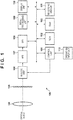
- FIG. 1 is a block diagram showing the functional configuration of the digital camera 100 according to an embodiment of the present invention.
- a control unit 101 is a CPU, for example, and controls operations of blocks included in the digital camera 100. Specifically, the control unit 101 controls operations of the blocks by reading out and extracting from a RAM 103 operation programs for image capture processing (described later), or refocus moving image generation processing that are stored in a ROM 102, and executing the read operation programs.
- the ROM 102 is a rewritable non-volatile memory, for example, and stores parameters and so on that are necessary for the operations of the blocks, in addition to storing the operation programs of the blocks included in the digital camera 100.
- the RAM 103 is a volatile memory.
- the RAM 103 is not only used as a region where the operation programs of the blocks included in the digital camera 100 are extracted, but also as a storage region where intermediate data and so on that are output in the operations in the blocks are stored.
- the imaging unit 106 is an imaging element such as a CCD or a CMOS sensor, for example.
- the imaging unit 106 receives a timing signal output from a timing generator (TG) (not shown) as a result of receiving an instruction from the control unit 101, and photoelectrically converts an optical image that is formed by an imaging optical system 104 on the plane of a photoelectric conversion element of the imaging element and outputs an analog image signal.
- TG timing generator
- the imaging optical system 104 includes, for example, a field lens, a focus lens, an aperture and so on.
- the digital camera 100 of the present embodiment has a microlens array 105 between the imaging optical system 104 and the imaging element on an optical axis, separately from the microlenses provided in photoelectric conversion elements of the imaging element.
- microlens array 105 provided between the imaging optical system 104 and the imaging element on the optical axis in the digital camera 100 of the present embodiment is described using diagrams.
- the microlens array 105 of the present embodiment is configured with a plurality of microlenses 201.
- the optical axis of the imaging optical system 104 is denoted as the z axis
- the horizontal direction of the digital camera 100 in a horizontal position is denoted as the x axis
- the vertical direction thereof is denoted as the y axis.
- the photoelectric conversion devices 202 of the imaging element that constitutes the imaging unit 106 are shown in a grid in FIG. 2 .
- a predetermined number of the photoelectric conversion elements 202 are associated with each microlens 201, and photoelectric conversion elements 202 having 25 (5x5) pixels are associated with one microlens 201 in the example of FIG. 2 .
- the number and arrangement of photoelectric conversion elements is not limited to this.
- the light flux that has passed through one microlens 201 is separated depending on the incidence direction, and an image is formed in the corresponding photoelectric conversion elements 202.
- FIG. 3 is a diagram showing the light flux incident on the photoelectric conversion elements 202-p1 to p5 corresponding to one microlens 201.
- a direction out of the plane of the paper corresponds to the vertical Y-axis direction of Fig. 2 .
- a light path of the light flux incident on the photoelectric conversion element 202 is illustrated as viewed from the lateral direction (y-axis) in a state in which the digital camera 100 is in the so-called horizontal position. As shown in FIG.
- the light flux that has passed through five regions a1 to a5 into which an exit pupil 301 of the imaging optical system 104 is vertically divided is incident on the photoelectric conversion elements 202-p1 to p5 arranged in the horizontal direction via one microlens 201. It should be noted that the number given to each region shows the correspondence relationship between the light flux that has passed therethrough and the light flux that is incident on the photoelectric conversion elements 202.
- each photoelectric conversion element 202 as viewed from the lateral direction is shown in the example of FIG. 3 , separation of the light flux is not limited to the vertical direction and is similarly performed in the horizontal direction.
- the exit pupil 301 of the imaging optical system 104 is classified into regions such as in FIG. 4A , the light flux that has passed through each region is incident on the photoelectric conversion element to which the same identification number is given among the photoelectric conversion elements 202 shown in FIG. 4B .
- the f-number of the imaging optical system 104 substantially matches that of microlenses of the microlens array 105.
- an AFE (Analog Front End) 107 and a DFE (Digital Front End) 108 perform correction processing and the like on image signals generated by the imaging unit 106.
- the AFE 107 adjusts a reference level (clamp processing) and performs A/D conversion processing on analog image signals output from the imaging unit 106, and outputs LF data to the DFE 108.
- the DFE 108 corrects minute shifts in the reference level and the like of the input LF data.
- An image processing unit 109 applies various image processes such as color conversion processing to the LF data to which correction processing has been applied by the DFE 108. Also, the image processing unit 109 performs processing in which an image (reconstruction image) in which an arbitrary subject distance is focused is generated from the LF data in the present embodiment.
- the method of "Light Field Photography" shown by Ren described above may be used to generate the reconstruction image.
- the combination of the imaging optical system 104, the microlens array 105, the imaging unit 106, the AFE 107, DFE 108 and the image processing unit 109 may be thought of as an obtaining means for obtaining an image signal that is capable of generating a plurality of reconstructions images.
- the image processing unit 109 generates images corresponding to two light fluxes that have passed through different divided pupil regions from LF data, and detects a difference (a defocus amount) in the image of the specific subject between the images.
- the control unit 101 is capable of calculating the subject distance at which a specific subject is focused based on the defocus amount detected in this manner.
- determinations or processes, which refer to subject distances, described below may be realized by referring to corresponding defocus amounts instead of subject distances.
- an A image can be generated that corresponds to the divided pupil regions on the left half of the exit pupil 301, and that is generated by adding pixel values of pixels in a first column and a second column among the corresponding pixels.
- a B image can be generated that corresponds to the divided pupil regions on the right half of the exit pupil 301, and that is generated by adding pixel values of pixels in a fourth column and a fifth column among the corresponding pixels.
- the two types of reconstruction images obtained in this manner are images in which the centroid position of the corresponding divided pupil regions serves as the optical axis.
- two types of reconstruction images have image differences caused by differences in the optical axes, and thus the amount of difference in the images (pupil division phase difference) with regard to each subject can be detected by performing a correlation operation on the two images.
- a subject distance in which each subject included in an image capture range in the LF data is focused can be analyzed from the image difference amount obtained in this manner, and, for example, a reconstruction image in which a specific subject is focused can be generated as an additional image.
- a plurality of pixels assigned to one microlens each receives light flux that has passed through different divided pupil regions of the exit pupil of an imaging lens. This similarly applies to all microlenses of the microlens array 105. Also, because the light flux that has passed through the imaging lens is incident on each microlens from different directions, all of the pixels of the imaging element each receive the light flux from different directions.
- each light flux is defined as coordinates (u, v) of a pupil region in the exit pupil through which the light flux has passed, and as position coordinates (x', y') of the corresponding microlens.
- FIG. 5 the light path of the light flux in a horizontal plane (xz plane) viewed from a vertical direction of the digital camera 100 in a horizontal position is shown.
- xz plane the light path of the light flux passing through each pixel of the reconstruction plane on an xz plane.
- F is a distance from an imaging lens to the microlens array
- ⁇ F is a distance from the imaging lens to a reconstruction plane
- ⁇ is a refocus coefficient: a variable coefficient for determining a distance to the reconstruction plane
- a pixel output E (x, y) at coordinates (x, y) of an image formed on the reconstruction plane is obtained by integrating L (x', y', u, v) with regard to a pupil region of the imaging lens and is expressed as follows.
- E x y 1 ⁇ 2 F 2 ⁇ L u + x ⁇ u ⁇ + v + y ⁇ v ⁇ , u , v dudv
- a displaying unit 110 is, for example, a displaying medium included in the digital camera 100 such as a small LCD.
- the displaying unit 110 displays an image that is generated by the image processing unit 109 and in which an arbitrary subject distance is focused.
- the control unit 101 controls the display on displaying unit 110, and may be considered as a display control means 101.
- images are not continuous in adjacent pixels. Accordingly, the displaying unit 110 displays image data generated by the image processing unit 109 instead of LF data.
- the present embodiment is described using the digital camera 100 as an example of image processing apparatuses, and thus description is given in which the displaying unit 110 is integrated in the digital camera 100, the present invention is not limited to this embodiment.
- display of a reconstruction image generated by an image processing apparatus may be controlled so that the reconstruction image is displayed on an external display apparatus connected to the image processing apparatus, and the display apparatus is not necessarily integrated in an image processing apparatus.
- a recording medium 111 is, for example, an internal memory included in the digital camera 100, or a recording apparatus such as a memory card or a HDD that is detachably connected to the digital camera 100.
- the recording medium 111 records LF data, and an image that is generated from such LF data and in which an arbitrary subject distance is focused.
- An operation input unit 112 is a user interface included in the digital camera 100, such as a power button or a shutter button, for example. Upon detecting that a user has operated the user interface, the operation input unit 112 outputs a control signal or a command that corresponds to the operation to the control unit 101.
- the displaying unit 110 of the present embodiment is a touch panel display that detects a touch input
- the operation input unit 112 receives a signal output from a sensor that performed the touch detection, analyzes the operation resulting from the touch input, and outputs a corresponding command to the control unit 101.
- the operation input unit 112 of the present embodiment determines that an operation related to enlarged display was performed.
- the operation input unit 112 determines that an operation related to reduced display was performed.
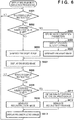
- step S601 the control unit 101 determines whether an instruction for enlarged display of a reconstruction image has been given. Specifically, the control unit 101 performs the determination of this step by determining whether or not a control signal that indicates that enlarged display has been performed is received from the operation input unit 112. In the case of determining that an instruction for enlarged display of a reconstruction image has been given, the control unit 101 stores in the RAM 103, as enlarged display parameters, information that is included in the control signal on, for example, coordinates that will be at the center of the image after enlarged display is performed, and on the display magnification after enlarged display is performed, and moves the processing to step S602. Also, in the case of determining that an instruction for performing enlarged display of a reconstruction image is not given, the control unit 101 repeats the processing in this step.
- step S602 the control unit 101 determines whether or not the digital camera 100 is currently set to change the subject distance to be focused when enlarged display of the reconstruction image is performed.
- the user controls the digital camera 100 of the present embodiment so as to change the subject distance to be focused at the time of enlarged display or reduced display while another touch input, other than the touch input related to enlarged display, is given in a predetermined region within a display region of the displaying unit 110.
- This may be performed by the control unit 101 setting true logic-based information (focus change flag) stored in the RAM 103, and referring to the information in this step while receiving control signals corresponding to the touch input from the operation input unit 112, for example.
- the switching is not limited to a touch input and may be performed in response to other operation inputs.
- the switching may be carried out in response to, for example, an operation input related to a setting change in the viewing mode being performed, the switching is preferably performed by a simple operation that is easily input along with the operation input for enlarged display or reduced display in order to facilitate the switching by the user.
- the switching may be carried out through input to an operation member such as a predetermined switch or button.
- the control unit 101 moves the processing to step S604 in the case of determining that changing the subject distance to be focused at the time of enlarged display is currently set, and moves the processing to step S603 in the case of determining that this is not the case.
- step S603 under the control of the control unit 101, the image processing unit 109 generates a reconstruction image with regard to a subject distance used in the generation of the reconstruction image that is currently displayed on the displaying unit 110.
- the image processing unit 109 then extracts an image of a region to be enlarged that is indicated by enlarged display parameters, and generates an enlarged image that is enlarged to a designated display magnification.
- an enlarged image may be generated using this image.
- control unit 101 performs processing as follows in step S604.
- the control unit 101 stores various image generation parameters in the RAM 103, including information on the subject distance used in the generation of the reconstruction image that is currently displayed on the displaying unit 110.
- step S605 the control unit 101 refers to the enlarged display parameters, and specifies a subject distance in which a subject included in a region to be enlarged is focused.
- a subject distance in which a subject included in a region to be enlarged is focused may be a subject distance in which a subject that is present in the center of the region is focused, for example.
- the subject distance may be determined based on the distance range into which the majority of subjects (pixels) are classified.
- any criterion may be used to specify the subject distance, as long as the subject distance specified in this step is a subject distance in which one of the subjects included in the region is focused, in the case of generating a reconstruction image based on the subject distance.
- subject distances calculated by a method based on the amount of differences in images as described above may be used in specifying the subject distances.
- step S606 under the control of the control unit 101, the image processing unit 109 newly generates a reconstruction image in which the subject in the subject distance is focused from LF data, based on a subject distance in which a subject in the subject distance specified in step S605 is focused.
- the image processing unit 109 then extracts an image in a region to be enlarged from the reconstruction image, and generates an enlarged image that is enlarged to a designated display magnification.
- step S607 the control unit 101 sends to and causes the displaying unit 110 to display the enlarged image generated by the image processing unit 109.
- step S608 the control unit 101 determines whether or not an instruction for performing reduced display of the enlarged reconstruction image, that is displayed, is given.
- an instruction for performing reduced display of the enlarged image after enlarged display is given, display magnification is restored to the original display magnification before the enlarged display
- the present invention is not limited to this embodiment.
- the display magnification may be reduced to another display magnification different from the original display magnification due to reduction.
- the control unit 101 moves the processing to step S609 in the case of determining that an instruction for performing reduced display of the enlarged reconstruction image that is displayed is given, and repeats the processing of this step in the case of determining that the instruction is not given.
- step S609 the control unit 101 determines whether or not the digital camera 100 is currently set to change the subject distance to be focused at the time of reducing and displaying the enlarged reconstruction image that is displayed.
- the control unit 101 refers to a focus change flag stored in the RAM 103 and determines whether or not the flag is on. It should be noted that although in the present embodiment, description is given in which the determination is performed depending on whether the same operation input is performed for whether or not a subject distance is changed at the time of enlarged display, and for whether or not a subject distance is changed at the time of reduced display, the determination may be performed based on different operation inputs.
- the control unit 101 moves the processing to step S611 in the case of determining that changing the subject distance to be focused at the time of reduced display is currently set, and moves the processing to step S610 in the case of determining that this is not the case.
- step S610 under the control of control unit 101, the image processing unit 109 generates a reconstruction image with regard to a subject distance used in the generation of the reconstruction image from which the enlarged image that is currently displayed on the displaying unit 110 is extracted.
- the reconstruction image generated in this step is an image in a focused state similar to the enlarged reconstruction image that is displayed. Accordingly, for example, in the case where a subject distance to be focused at the time of enlarged display is changed, a reconstruction image in a state in which the change is maintained at the time of reduction is displayed on the displaying unit 110.
- this image may be used.
- the control unit 101 obtains information on the subject distance used in the generation of the reconstruction image displayed on the displaying unit 110 before performing enlarged display, in step S611. Specifically, the control unit 101 reads out image generation parameters with regard to the reconstruction image displayed before enlarged display from the RAM 103 and obtains the information. It should be noted that because description is given in which image generation parameters are stored in step S604 in the present display enlargement/reduction processing, in other words, image generation parameters are stored only in the case where the subject distance is changed at the time of enlarged display, the image generation parameters do not exist in the case where the subject distance is not changed at the time of enlarged display.
- the image processing unit 109 also generates a reconstruction image at the time of generation of the enlarged image using the same parameters as those used before enlarged display and thus the image processing unit 109 holds the parameters.
- the present invention is not limited to this, and it may be configured that image generation parameters are stored in the RAM 103 when an instruction for performing enlarged display is given, regardless of whether the subject distance is changed at the time of enlarged display. Thereby, for example, even if a subject distance to be focused is changed after enlarged display, it is possible to refer to image generation parameters prior to enlarged display. Also, when the subject distance to be focused is changed after enlarged display instead of before enlarged display, image generation parameters may be stored.
- step S612 based on the subject distance used in the generation of the reconstruction image displayed on the displaying unit 110 before performing enlarged display, the image processing unit 109 newly generates a reconstruction image in which the subject distance is focused from LF data under the control of the control unit 101.
- a reconstruction image generated in this step is an image in a focused state in which the reconstruction image does not necessarily correspond to the enlarged reconstruction image that is displayed.
- the change is discarded at the time of reduction, and a reconstruction image in a focused state that is the same as the reconstruction image displayed before enlarged display is displayed on the displaying unit 110.
- step S613 the control unit 101 sends the reconstruction image generated by the image processing unit 109 to the displaying unit 110 and causes the displaying unit 110 to display the image, before moving the processing to step S601.
- a user is able to easily view a reconstruction image in a desired focused state in the case of performing an operation related to enlarged display or reduced display in which display magnification is restored to the original display magnification after enlarged display.
- parameters are separately stored, and thereby when an instruction for performing reduced display of the enlarged image in the second stage is given, the image can be returned to the enlarged image in the first stage.
- the image can be returned to the reconstruction image before enlarged display in the first stage was performed.
- the image processing unit 109 has a function of detecting the image of a person from an image
- a configuration may be adopted in which changing the subject distance to be focused is set, only in the case where the image processing unit 109 determines that enlarged display is an operation for determining a focused state of the person, and the person is not focused in the displayed reconstruction image. Accordingly, it is possible to check the details of the focused state of the person due to enlarged display. Also, in the case where the focused state is slightly out of focus in normal display, or in the case where nobody is focused in normal display, it is possible to focus on a person in a region to be displayed after enlarged display, and to forcibly keep the focused state after reduced display.
- the focused state of the person may be forcibly kept even if enlarged display/reduced display is performed thereafter. It should be noted that such control is not limited to people, and may be performed using a subject detection function of detecting a preset specific subject.
- an image processing apparatus of the present embodiment is capable of easily changing a focused state of a reconstruction image to be displayed after an operation related to enlarged display or reduced display.
- Embodiment(s) of the present invention can also be realized by a computer of a system or apparatus that reads out and executes computer executable instructions (e.g., one or more programs) recorded on a storage medium (which may also be referred to more fully as a 'non-transitory computer-readable storage medium') to perform the functions of one or more of the above-described embodiment(s).
- a storage medium which may also be referred to more fully as a 'non-transitory computer-readable storage medium'
- the computer of the system or apparatus may include one or more circuits (e.g., application specific integrated circuit (ASIC)) for performing the functions of one or more of the above-described embodiment(s).
- ASIC application specific integrated circuit
- the computer of the system or apparatus may perform a method by, for example, reading out and executing the computer executable instructions from the storage medium to perform the functions of one or more of the above-described embodiment(s), and/or controlling the one or more circuits to perform the functions of one or more of the above-described embodiment(s).
- the computer may comprise one or more processors (e.g., central processing unit (CPU), micro processing unit (MPU)) and may include a network of separate computers or separate processors to read out and execute the computer executable instructions.
- the computer executable instructions may be provided to the computer, for example, from a network or the storage medium.
- the storage medium may include, for example, one or more of a hard disk, a random-access memory (RAM), a read only memory (ROM), a storage of distributed computing systems, an optical disk (such as a compact disc (CD), digital versatile disc (DVD), or Blu-ray Disc (BD)TM), a flash memory device, a memory card, and the like.
- RAM random-access memory
- ROM read only memory
- BD Blu-ray Disc
Landscapes
- Engineering & Computer Science (AREA)
- Multimedia (AREA)
- Signal Processing (AREA)
- Human Computer Interaction (AREA)
- Studio Devices (AREA)
- Focusing (AREA)
- Automatic Focus Adjustment (AREA)
- Image Processing (AREA)
Applications Claiming Priority (2)
| Application Number | Priority Date | Filing Date | Title |
|---|---|---|---|
| JP2014032151A JP6321991B2 (ja) | 2014-02-21 | 2014-02-21 | 画像処理装置、制御方法、プログラム、及び記録媒体 |
| EP15155808.7A EP2911383B1 (de) | 2014-02-21 | 2015-02-19 | Bildverarbeitungsvorrichtung, steuerungsverfahren, programm und aufzeichnungsmedium |
Related Parent Applications (1)
| Application Number | Title | Priority Date | Filing Date |
|---|---|---|---|
| EP15155808.7A Division EP2911383B1 (de) | 2014-02-21 | 2015-02-19 | Bildverarbeitungsvorrichtung, steuerungsverfahren, programm und aufzeichnungsmedium |
Publications (2)
| Publication Number | Publication Date |
|---|---|
| EP3570533A1 true EP3570533A1 (de) | 2019-11-20 |
| EP3570533B1 EP3570533B1 (de) | 2024-12-11 |
Family
ID=52573614
Family Applications (2)
| Application Number | Title | Priority Date | Filing Date |
|---|---|---|---|
| EP15155808.7A Active EP2911383B1 (de) | 2014-02-21 | 2015-02-19 | Bildverarbeitungsvorrichtung, steuerungsverfahren, programm und aufzeichnungsmedium |
| EP19178138.4A Active EP3570533B1 (de) | 2014-02-21 | 2015-02-19 | Bildverarbeitungsvorrichtung, steuerungsverfahren, programm und aufzeichnungsmedium |
Family Applications Before (1)
| Application Number | Title | Priority Date | Filing Date |
|---|---|---|---|
| EP15155808.7A Active EP2911383B1 (de) | 2014-02-21 | 2015-02-19 | Bildverarbeitungsvorrichtung, steuerungsverfahren, programm und aufzeichnungsmedium |
Country Status (3)
| Country | Link |
|---|---|
| US (1) | US9723213B2 (de) |
| EP (2) | EP2911383B1 (de) |
| JP (1) | JP6321991B2 (de) |
Families Citing this family (3)
| Publication number | Priority date | Publication date | Assignee | Title |
|---|---|---|---|---|
| JP6736270B2 (ja) * | 2015-07-13 | 2020-08-05 | キヤノン株式会社 | 画像処理装置及び画像処理装置の作動方法 |
| JP6689656B2 (ja) * | 2016-04-18 | 2020-04-28 | ルネサスエレクトロニクス株式会社 | 画像処理システム、画像処理方法及び画像送信装置 |
| WO2018055659A1 (ja) * | 2016-09-20 | 2018-03-29 | 株式会社オプティム | 画面共有システム、画面共有方法及びプログラム |
Citations (4)
| Publication number | Priority date | Publication date | Assignee | Title |
|---|---|---|---|---|
| US20110129165A1 (en) * | 2009-11-27 | 2011-06-02 | Samsung Electronics Co., Ltd. | Image processing apparatus and method |
| EP2566150A2 (de) * | 2011-09-01 | 2013-03-06 | Canon Kabushiki Kaisha | Bildverarbeitungsvorrichtung, Bildverarbeitungsverfahren und Programm |
| US20130128069A1 (en) * | 2010-08-27 | 2013-05-23 | Todor G. Georgiev | Methods and Apparatus for Rendering Output Images with Simulated Artistic Effects from Focused Plenoptic Camera Data |
| US20140049666A1 (en) * | 2012-08-14 | 2014-02-20 | Canon Kabushiki Kaisha | Image processing device, image capturing device including image processing device, image processing method, and program |
Family Cites Families (4)
| Publication number | Priority date | Publication date | Assignee | Title |
|---|---|---|---|---|
| JP4969474B2 (ja) * | 2007-02-09 | 2012-07-04 | オリンパスイメージング株式会社 | 復号方法、復号装置、及び復号プログラム |
| JP5463739B2 (ja) * | 2009-06-03 | 2014-04-09 | ソニー株式会社 | 撮像装置、画像処理方法及びプログラム |
| JP6080417B2 (ja) * | 2011-08-19 | 2017-02-15 | キヤノン株式会社 | 画像処理装置、及び画像処理方法 |
| JP6188290B2 (ja) * | 2012-08-03 | 2017-08-30 | キヤノン株式会社 | 測距装置、撮像装置、ピント評価方法、プログラム及び記憶媒体 |
-
2014
- 2014-02-21 JP JP2014032151A patent/JP6321991B2/ja active Active
-
2015
- 2015-02-19 EP EP15155808.7A patent/EP2911383B1/de active Active
- 2015-02-19 EP EP19178138.4A patent/EP3570533B1/de active Active
- 2015-02-19 US US14/626,379 patent/US9723213B2/en active Active
Patent Citations (4)
| Publication number | Priority date | Publication date | Assignee | Title |
|---|---|---|---|---|
| US20110129165A1 (en) * | 2009-11-27 | 2011-06-02 | Samsung Electronics Co., Ltd. | Image processing apparatus and method |
| US20130128069A1 (en) * | 2010-08-27 | 2013-05-23 | Todor G. Georgiev | Methods and Apparatus for Rendering Output Images with Simulated Artistic Effects from Focused Plenoptic Camera Data |
| EP2566150A2 (de) * | 2011-09-01 | 2013-03-06 | Canon Kabushiki Kaisha | Bildverarbeitungsvorrichtung, Bildverarbeitungsverfahren und Programm |
| US20140049666A1 (en) * | 2012-08-14 | 2014-02-20 | Canon Kabushiki Kaisha | Image processing device, image capturing device including image processing device, image processing method, and program |
Non-Patent Citations (1)
| Title |
|---|
| REN. NG ET AL.: "Light Field Photography with a Hand-Held Plenoptic Camera", STANFORD TECH REPORT CTSR, February 2005 (2005-02-01) |
Also Published As
| Publication number | Publication date |
|---|---|
| US20150244941A1 (en) | 2015-08-27 |
| EP2911383B1 (de) | 2019-07-03 |
| JP2015158736A (ja) | 2015-09-03 |
| US9723213B2 (en) | 2017-08-01 |
| EP2911383A1 (de) | 2015-08-26 |
| JP6321991B2 (ja) | 2018-05-09 |
| EP3570533B1 (de) | 2024-12-11 |
Similar Documents
| Publication | Publication Date | Title |
|---|---|---|
| US9208569B2 (en) | Image processing apparatus and control method thereof capable of performing refocus calculation processing for light field data | |
| US10200590B2 (en) | Image pickup apparatus and method of controlling the same | |
| US9712740B2 (en) | Image processing apparatus, imaging apparatus, image processing method, and storage medium | |
| US20150358542A1 (en) | Image processing apparatus, image capturing apparatus, image processing method, image capturing method, and non-transitory computer-readable medium for focus bracketing | |
| US10855903B2 (en) | Image processing apparatus, image capturing apparatus, control method and recording medium | |
| US11831979B2 (en) | Image pickup apparatus, an image processing method and a non-transitory computer-readable medium for displaying a plurality of images different in in-focus position | |
| US11323689B2 (en) | Image processing device, imaging device, image processing method, and recording medium | |
| US20140044420A1 (en) | Image processing apparatus, control method for same, and program | |
| EP3002940A1 (de) | Bildgebungsvorrichtung und abbildungsverfahren | |
| EP2866430B1 (de) | Bilderzeugungsvorrichtung und deren Steuerungsverfahren sowie Programm | |
| EP2512144B1 (de) | Bildverarbeitungsvorrichtung, Bildverarbeitungsverfahren und Programm | |
| US10148862B2 (en) | Image capturing apparatus, method for controlling image capturing apparatus focus area display, and storage medium | |
| JP2008281385A (ja) | 画像処理装置 | |
| EP2944997A1 (de) | Bildaufnahmevorrichtung, bildkorrekturverfahren, bildverarbeitungsvorrichtung und bildverarbeitungsverfahren | |
| EP3570533B1 (de) | Bildverarbeitungsvorrichtung, steuerungsverfahren, programm und aufzeichnungsmedium | |
| JP2013160991A (ja) | 撮像装置 | |
| US10003735B2 (en) | Calculation device and image pickup device using calculation device and calculation method | |
| US11985420B2 (en) | Image processing device, image processing method, program, and imaging device | |
| JP2017138434A (ja) | 撮像装置 | |
| US20180109720A1 (en) | Image processing apparatus, image processing method, and storage medium | |
| JP7373297B2 (ja) | 画像処理装置、画像処理方法及びプログラム | |
| US12342074B2 (en) | Image processing device, imaging device, method of controlling image processing device, and storage medium | |
| JP2014131188A (ja) | 撮像装置、その制御方法、および制御プログラム | |
| JP2020085967A (ja) | 画像処理装置およびその制御方法ならびにプログラム | |
| US20150365599A1 (en) | Information processing apparatus, image capturing apparatus, and control method |
Legal Events
| Date | Code | Title | Description |
|---|---|---|---|
| PUAI | Public reference made under article 153(3) epc to a published international application that has entered the european phase |
Free format text: ORIGINAL CODE: 0009012 |
|
| STAA | Information on the status of an ep patent application or granted ep patent |
Free format text: STATUS: THE APPLICATION HAS BEEN PUBLISHED |
|
| AC | Divisional application: reference to earlier application |
Ref document number: 2911383 Country of ref document: EP Kind code of ref document: P |
|
| AK | Designated contracting states |
Kind code of ref document: A1 Designated state(s): AL AT BE BG CH CY CZ DE DK EE ES FI FR GB GR HR HU IE IS IT LI LT LU LV MC MK MT NL NO PL PT RO RS SE SI SK SM TR |
|
| STAA | Information on the status of an ep patent application or granted ep patent |
Free format text: STATUS: REQUEST FOR EXAMINATION WAS MADE |
|
| 17P | Request for examination filed |
Effective date: 20200520 |
|
| RBV | Designated contracting states (corrected) |
Designated state(s): AL AT BE BG CH CY CZ DE DK EE ES FI FR GB GR HR HU IE IS IT LI LT LU LV MC MK MT NL NO PL PT RO RS SE SI SK SM TR |
|
| STAA | Information on the status of an ep patent application or granted ep patent |
Free format text: STATUS: EXAMINATION IS IN PROGRESS |
|
| 17Q | First examination report despatched |
Effective date: 20210409 |
|
| REG | Reference to a national code |
Ref country code: DE Ref legal event code: R079 Free format text: PREVIOUS MAIN CLASS: H04N0005232000 Ipc: H04N0023630000 Ref document number: 602015090638 Country of ref document: DE |
|
| GRAP | Despatch of communication of intention to grant a patent |
Free format text: ORIGINAL CODE: EPIDOSNIGR1 |
|
| STAA | Information on the status of an ep patent application or granted ep patent |
Free format text: STATUS: GRANT OF PATENT IS INTENDED |
|
| RIC1 | Information provided on ipc code assigned before grant |
Ipc: H04N 23/69 20230101ALI20240620BHEP Ipc: H04N 23/67 20230101ALI20240620BHEP Ipc: H04N 23/63 20230101AFI20240620BHEP |
|
| INTG | Intention to grant announced |
Effective date: 20240705 |
|
| GRAS | Grant fee paid |
Free format text: ORIGINAL CODE: EPIDOSNIGR3 |
|
| GRAA | (expected) grant |
Free format text: ORIGINAL CODE: 0009210 |
|
| STAA | Information on the status of an ep patent application or granted ep patent |
Free format text: STATUS: THE PATENT HAS BEEN GRANTED |
|
| AC | Divisional application: reference to earlier application |
Ref document number: 2911383 Country of ref document: EP Kind code of ref document: P |
|
| AK | Designated contracting states |
Kind code of ref document: B1 Designated state(s): AL AT BE BG CH CY CZ DE DK EE ES FI FR GB GR HR HU IE IS IT LI LT LU LV MC MK MT NL NO PL PT RO RS SE SI SK SM TR |
|
| REG | Reference to a national code |
Ref country code: GB Ref legal event code: FG4D |
|
| REG | Reference to a national code |
Ref country code: CH Ref legal event code: EP |
|
| REG | Reference to a national code |
Ref country code: IE Ref legal event code: FG4D |
|
| REG | Reference to a national code |
Ref country code: DE Ref legal event code: R096 Ref document number: 602015090638 Country of ref document: DE |
|
| REG | Reference to a national code |
Ref country code: LT Ref legal event code: MG9D |
|
| PG25 | Lapsed in a contracting state [announced via postgrant information from national office to epo] |
Ref country code: HR Free format text: LAPSE BECAUSE OF FAILURE TO SUBMIT A TRANSLATION OF THE DESCRIPTION OR TO PAY THE FEE WITHIN THE PRESCRIBED TIME-LIMIT Effective date: 20241211 |
|
| PG25 | Lapsed in a contracting state [announced via postgrant information from national office to epo] |
Ref country code: FI Free format text: LAPSE BECAUSE OF FAILURE TO SUBMIT A TRANSLATION OF THE DESCRIPTION OR TO PAY THE FEE WITHIN THE PRESCRIBED TIME-LIMIT Effective date: 20241211 |
|
| PG25 | Lapsed in a contracting state [announced via postgrant information from national office to epo] |
Ref country code: BG Free format text: LAPSE BECAUSE OF FAILURE TO SUBMIT A TRANSLATION OF THE DESCRIPTION OR TO PAY THE FEE WITHIN THE PRESCRIBED TIME-LIMIT Effective date: 20241211 |
|
| REG | Reference to a national code |
Ref country code: NL Ref legal event code: MP Effective date: 20241211 |
|
| PG25 | Lapsed in a contracting state [announced via postgrant information from national office to epo] |
Ref country code: ES Free format text: LAPSE BECAUSE OF FAILURE TO SUBMIT A TRANSLATION OF THE DESCRIPTION OR TO PAY THE FEE WITHIN THE PRESCRIBED TIME-LIMIT Effective date: 20241211 |
|
| PG25 | Lapsed in a contracting state [announced via postgrant information from national office to epo] |
Ref country code: NO Free format text: LAPSE BECAUSE OF FAILURE TO SUBMIT A TRANSLATION OF THE DESCRIPTION OR TO PAY THE FEE WITHIN THE PRESCRIBED TIME-LIMIT Effective date: 20250311 |
|
| PG25 | Lapsed in a contracting state [announced via postgrant information from national office to epo] |
Ref country code: LV Free format text: LAPSE BECAUSE OF FAILURE TO SUBMIT A TRANSLATION OF THE DESCRIPTION OR TO PAY THE FEE WITHIN THE PRESCRIBED TIME-LIMIT Effective date: 20241211 Ref country code: GR Free format text: LAPSE BECAUSE OF FAILURE TO SUBMIT A TRANSLATION OF THE DESCRIPTION OR TO PAY THE FEE WITHIN THE PRESCRIBED TIME-LIMIT Effective date: 20250312 |
|
| PG25 | Lapsed in a contracting state [announced via postgrant information from national office to epo] |
Ref country code: RS Free format text: LAPSE BECAUSE OF FAILURE TO SUBMIT A TRANSLATION OF THE DESCRIPTION OR TO PAY THE FEE WITHIN THE PRESCRIBED TIME-LIMIT Effective date: 20250311 |
|
| PG25 | Lapsed in a contracting state [announced via postgrant information from national office to epo] |
Ref country code: NL Free format text: LAPSE BECAUSE OF FAILURE TO SUBMIT A TRANSLATION OF THE DESCRIPTION OR TO PAY THE FEE WITHIN THE PRESCRIBED TIME-LIMIT Effective date: 20241211 |
|
| REG | Reference to a national code |
Ref country code: AT Ref legal event code: MK05 Ref document number: 1751304 Country of ref document: AT Kind code of ref document: T Effective date: 20241211 |
|
| PG25 | Lapsed in a contracting state [announced via postgrant information from national office to epo] |
Ref country code: SM Free format text: LAPSE BECAUSE OF FAILURE TO SUBMIT A TRANSLATION OF THE DESCRIPTION OR TO PAY THE FEE WITHIN THE PRESCRIBED TIME-LIMIT Effective date: 20241211 |
|
| PG25 | Lapsed in a contracting state [announced via postgrant information from national office to epo] |
Ref country code: PL Free format text: LAPSE BECAUSE OF FAILURE TO SUBMIT A TRANSLATION OF THE DESCRIPTION OR TO PAY THE FEE WITHIN THE PRESCRIBED TIME-LIMIT Effective date: 20241211 |
|
| PG25 | Lapsed in a contracting state [announced via postgrant information from national office to epo] |
Ref country code: IS Free format text: LAPSE BECAUSE OF FAILURE TO SUBMIT A TRANSLATION OF THE DESCRIPTION OR TO PAY THE FEE WITHIN THE PRESCRIBED TIME-LIMIT Effective date: 20250411 |
|
| PG25 | Lapsed in a contracting state [announced via postgrant information from national office to epo] |
Ref country code: PT Free format text: LAPSE BECAUSE OF FAILURE TO SUBMIT A TRANSLATION OF THE DESCRIPTION OR TO PAY THE FEE WITHIN THE PRESCRIBED TIME-LIMIT Effective date: 20250411 |
|
| PG25 | Lapsed in a contracting state [announced via postgrant information from national office to epo] |
Ref country code: EE Free format text: LAPSE BECAUSE OF FAILURE TO SUBMIT A TRANSLATION OF THE DESCRIPTION OR TO PAY THE FEE WITHIN THE PRESCRIBED TIME-LIMIT Effective date: 20241211 |
|
| PG25 | Lapsed in a contracting state [announced via postgrant information from national office to epo] |
Ref country code: RO Free format text: LAPSE BECAUSE OF FAILURE TO SUBMIT A TRANSLATION OF THE DESCRIPTION OR TO PAY THE FEE WITHIN THE PRESCRIBED TIME-LIMIT Effective date: 20241211 Ref country code: AT Free format text: LAPSE BECAUSE OF FAILURE TO SUBMIT A TRANSLATION OF THE DESCRIPTION OR TO PAY THE FEE WITHIN THE PRESCRIBED TIME-LIMIT Effective date: 20241211 |
|
| PG25 | Lapsed in a contracting state [announced via postgrant information from national office to epo] |
Ref country code: SK Free format text: LAPSE BECAUSE OF FAILURE TO SUBMIT A TRANSLATION OF THE DESCRIPTION OR TO PAY THE FEE WITHIN THE PRESCRIBED TIME-LIMIT Effective date: 20241211 |
|
| PG25 | Lapsed in a contracting state [announced via postgrant information from national office to epo] |
Ref country code: CZ Free format text: LAPSE BECAUSE OF FAILURE TO SUBMIT A TRANSLATION OF THE DESCRIPTION OR TO PAY THE FEE WITHIN THE PRESCRIBED TIME-LIMIT Effective date: 20241211 |
|
| PG25 | Lapsed in a contracting state [announced via postgrant information from national office to epo] |
Ref country code: IT Free format text: LAPSE BECAUSE OF FAILURE TO SUBMIT A TRANSLATION OF THE DESCRIPTION OR TO PAY THE FEE WITHIN THE PRESCRIBED TIME-LIMIT Effective date: 20241211 |
|
| PG25 | Lapsed in a contracting state [announced via postgrant information from national office to epo] |
Ref country code: SE Free format text: LAPSE BECAUSE OF FAILURE TO SUBMIT A TRANSLATION OF THE DESCRIPTION OR TO PAY THE FEE WITHIN THE PRESCRIBED TIME-LIMIT Effective date: 20241211 |
|
| REG | Reference to a national code |
Ref country code: DE Ref legal event code: R097 Ref document number: 602015090638 Country of ref document: DE |
|
| PG25 | Lapsed in a contracting state [announced via postgrant information from national office to epo] |
Ref country code: MC Free format text: LAPSE BECAUSE OF FAILURE TO SUBMIT A TRANSLATION OF THE DESCRIPTION OR TO PAY THE FEE WITHIN THE PRESCRIBED TIME-LIMIT Effective date: 20241211 |
|
| REG | Reference to a national code |
Ref country code: CH Ref legal event code: PL |
|
| PG25 | Lapsed in a contracting state [announced via postgrant information from national office to epo] |
Ref country code: DK Free format text: LAPSE BECAUSE OF FAILURE TO SUBMIT A TRANSLATION OF THE DESCRIPTION OR TO PAY THE FEE WITHIN THE PRESCRIBED TIME-LIMIT Effective date: 20241211 |
|
| PG25 | Lapsed in a contracting state [announced via postgrant information from national office to epo] |
Ref country code: LU Free format text: LAPSE BECAUSE OF NON-PAYMENT OF DUE FEES Effective date: 20250219 |
|
| PLBE | No opposition filed within time limit |
Free format text: ORIGINAL CODE: 0009261 |
|
| STAA | Information on the status of an ep patent application or granted ep patent |
Free format text: STATUS: NO OPPOSITION FILED WITHIN TIME LIMIT |
|
| PG25 | Lapsed in a contracting state [announced via postgrant information from national office to epo] |
Ref country code: CH Free format text: LAPSE BECAUSE OF NON-PAYMENT OF DUE FEES Effective date: 20250228 |
|
| 26N | No opposition filed |
Effective date: 20250912 |
|
| GBPC | Gb: european patent ceased through non-payment of renewal fee |
Effective date: 20250311 |
|
| REG | Reference to a national code |
Ref country code: BE Ref legal event code: MM Effective date: 20250228 |
|
| PG25 | Lapsed in a contracting state [announced via postgrant information from national office to epo] |
Ref country code: GB Free format text: LAPSE BECAUSE OF NON-PAYMENT OF DUE FEES Effective date: 20250311 |
|
| PG25 | Lapsed in a contracting state [announced via postgrant information from national office to epo] |
Ref country code: FR Free format text: LAPSE BECAUSE OF NON-PAYMENT OF DUE FEES Effective date: 20250228 |
|
| PG25 | Lapsed in a contracting state [announced via postgrant information from national office to epo] |
Ref country code: BE Free format text: LAPSE BECAUSE OF NON-PAYMENT OF DUE FEES Effective date: 20250228 |
|
| PG25 | Lapsed in a contracting state [announced via postgrant information from national office to epo] |
Ref country code: IE Free format text: LAPSE BECAUSE OF NON-PAYMENT OF DUE FEES Effective date: 20250219 |
|
| PGFP | Annual fee paid to national office [announced via postgrant information from national office to epo] |
Ref country code: DE Payment date: 20260121 Year of fee payment: 12 |