EP3570403A1 - Electronic cigarette and battery protection circuit thereof - Google Patents
Electronic cigarette and battery protection circuit thereof Download PDFInfo
- Publication number
- EP3570403A1 EP3570403A1 EP17891131.9A EP17891131A EP3570403A1 EP 3570403 A1 EP3570403 A1 EP 3570403A1 EP 17891131 A EP17891131 A EP 17891131A EP 3570403 A1 EP3570403 A1 EP 3570403A1
- Authority
- EP
- European Patent Office
- Prior art keywords
- connecting end
- battery
- switch unit
- protection circuit
- switch
- Prior art date
- Legal status (The legal status is an assumption and is not a legal conclusion. Google has not performed a legal analysis and makes no representation as to the accuracy of the status listed.)
- Withdrawn
Links
Images


Classifications
-
- H—ELECTRICITY
- H02—GENERATION; CONVERSION OR DISTRIBUTION OF ELECTRIC POWER
- H02H—EMERGENCY PROTECTIVE CIRCUIT ARRANGEMENTS
- H02H7/00—Emergency protective circuit arrangements specially adapted for specific types of electric machines or apparatus or for sectionalised protection of cable or line systems, and effecting automatic switching in the event of an undesired change from normal working conditions
- H02H7/18—Emergency protective circuit arrangements specially adapted for specific types of electric machines or apparatus or for sectionalised protection of cable or line systems, and effecting automatic switching in the event of an undesired change from normal working conditions for batteries; for accumulators
-
- H—ELECTRICITY
- H02—GENERATION; CONVERSION OR DISTRIBUTION OF ELECTRIC POWER
- H02J—ELECTRIC POWER NETWORKS; CIRCUIT ARRANGEMENTS OR SYSTEMS FOR SUPPLYING OR DISTRIBUTING ELECTRIC POWER; SYSTEMS FOR STORING ELECTRIC ENERGY
- H02J7/00—Circuit arrangements for charging or discharging batteries or for supplying loads from batteries
- H02J7/60—Circuit arrangements for charging or discharging batteries or for supplying loads from batteries including safety or protection arrangements
- H02J7/68—Circuit arrangements for charging or discharging batteries or for supplying loads from batteries including safety or protection arrangements using circuits for correcting or protecting against reverse-polarity
-
- A—HUMAN NECESSITIES
- A24—TOBACCO; CIGARS; CIGARETTES; SIMULATED SMOKING DEVICES; SMOKERS' REQUISITES
- A24F—SMOKERS' REQUISITES; MATCH BOXES; SIMULATED SMOKING DEVICES
- A24F40/00—Electrically operated smoking devices; Component parts thereof; Manufacture thereof; Maintenance or testing thereof; Charging means specially adapted therefor
- A24F40/50—Control or monitoring
-
- H—ELECTRICITY
- H01—ELECTRIC ELEMENTS
- H01M—PROCESSES OR MEANS, e.g. BATTERIES, FOR THE DIRECT CONVERSION OF CHEMICAL ENERGY INTO ELECTRICAL ENERGY
- H01M50/00—Constructional details or processes of manufacture of the non-active parts of electrochemical cells other than fuel cells, e.g. hybrid cells
- H01M50/50—Current conducting connections for cells or batteries
- H01M50/572—Means for preventing undesired use or discharge
- H01M50/574—Devices or arrangements for the interruption of current
-
- H—ELECTRICITY
- H02—GENERATION; CONVERSION OR DISTRIBUTION OF ELECTRIC POWER
- H02J—ELECTRIC POWER NETWORKS; CIRCUIT ARRANGEMENTS OR SYSTEMS FOR SUPPLYING OR DISTRIBUTING ELECTRIC POWER; SYSTEMS FOR STORING ELECTRIC ENERGY
- H02J7/00—Circuit arrangements for charging or discharging batteries or for supplying loads from batteries
- H02J7/50—Circuit arrangements for charging or discharging batteries or for supplying loads from batteries acting upon multiple batteries simultaneously or sequentially
- H02J7/52—Circuit arrangements for charging or discharging batteries or for supplying loads from batteries acting upon multiple batteries simultaneously or sequentially for charge balancing, e.g. equalisation of charge between batteries
- H02J7/54—Passive balancing, e.g. using resistors or parallel MOSFETs
-
- Y—GENERAL TAGGING OF NEW TECHNOLOGICAL DEVELOPMENTS; GENERAL TAGGING OF CROSS-SECTIONAL TECHNOLOGIES SPANNING OVER SEVERAL SECTIONS OF THE IPC; TECHNICAL SUBJECTS COVERED BY FORMER USPC CROSS-REFERENCE ART COLLECTIONS [XRACs] AND DIGESTS
- Y02—TECHNOLOGIES OR APPLICATIONS FOR MITIGATION OR ADAPTATION AGAINST CLIMATE CHANGE
- Y02E—REDUCTION OF GREENHOUSE GAS [GHG] EMISSIONS, RELATED TO ENERGY GENERATION, TRANSMISSION OR DISTRIBUTION
- Y02E60/00—Enabling technologies; Technologies with a potential or indirect contribution to GHG emissions mitigation
- Y02E60/10—Energy storage using batteries
Definitions
- the present application relates to the technical field of smoking simulation, and more particularly, to an electronic cigarette and a battery protection circuit of the electronic cigarette.
- an electronic cigarette is also provided.
- a battery protection circuit is configured for connecting with a battery.
- the battery protection circuit includes a first connecting end and a second connecting end.
- the first connecting end is configured for connecting with an electrode of the battery, and the second connecting end is configured for connecting with an opposite electrode of the battery.
- the battery protection circuit further includes a third connecting end, a fourth connecting end, a fifth connecting end and a sixth connecting end.
- the third connecting end and the fourth connecting end are both configured for connecting with a positive voltage terminal.
- the fifth connecting end and the sixth connecting end are both configured for connecting with the ground terminal.
- the third connecting end is in connection with the first connecting end and the fifth connecting end is in connection with the second connecting end.
- the sixth connecting end is in connection with the first connecting end and the fourth connecting end is in connection with the second connecting end.
- the battery protection circuit includes a first switch unit, a second switch unit, a third switch unit and a fourth switch unit.
- Each switch unit has three ends, the three ends of each switch unit are comprised of a first end, a second end and a control end. The turning on or off between the first end and the second end is controlled according to the voltage level applied on the control end.
- the first switch unit and the fourth switch unit are controlled to be turned on under a high-level voltage, and controlled to be turned off under a low-level voltage.
- the second switch unit and the third switch unit are controlled to be turned on under a low-level voltage, and controlled to be turned off under a high-level voltage.
- the first end acts as the third connecting end and is connected to the positive voltage terminal, the second end and the control end are both connected to the first connecting end.
- the first end acts as the sixth connecting end and is connected to the ground terminal, the second end and the control end are both connected to the first connecting end.
- the first end acts as the fifth connecting end and is connected to the ground terminal, the second end and the control end are both connected to the second connecting end.
- the first end acts as the fourth connecting end and is connected to the positive voltage terminal
- the second end and the control end are both connected to the second connecting end.
- both the first switch unit and the fourth switch unit are NMOS transistors, the first end is a source terminal, the second end is a drain terminal, and the control end is a gate terminal.
- Both the second switch unit and the third switch unit are PMOS transistors, the first end is a source terminal, the second end is a drain terminal, and the control end is a gate terminal.
- each of the first switch unit and the fourth switch unit adopts an AON6512 chip.
- the 1 st to 3 rd pins of the AON6512 chip of the first switch unit are led out for acting as the third connecting end and connecting with the positive voltage terminal, and the 4 th to 8 th pins of the AON6512 chip of the first switch unit are connected to the first connecting end.
- the 1 st to 3 rd pins of the AON6512 chip of the fourth switch unit are led out for acting as the fourth connecting end and connecting with the positive voltage terminal, and the 4 th to 8 th pins of the AON6512 chip of the fourth switch unit are connected to the second connecting end.
- Each of the second switch unit and the third switch unit adopts an AON6411 chip.
- the 1 st to 3 rd pins of the AON6411 chip of the second switch unit are led out for acting as the sixth connecting end and connecting with the ground terminal, and the 4 th to 8 th pins of the AON6411 chip of the second switch unit are connected to the first connecting end.
- the 1 st to 3 rd pins of the AON6411 chip of the third switch unit are led out for acting as the fifth connecting end and connecting with the ground terminal, and the 4 th to 8 th pins of the AON6411 chip of the third switch unit are connected to the second connecting end.
- the battery protection circuit includes a first relay switch module and a second relay switch module.
- the first relay switch module includes a first coil and a first switch.
- the second relay switch module includes a second coil and a second switch.
- the normally opened contact of the first switch acts as the third connecting end and is connected to the positive voltage terminal
- the normally closed contact of the first switch acts as the sixth connecting end and is connected to the ground terminal
- the common contact of the first switch is connected to the first connecting end.
- the normally opened contact of the second switch acts as the fifth connecting end and is connected to the ground terminal
- the normally closed contact of the second switch acts as the fourth connecting end and is connected to the positive voltage terminal
- the common contact of the second switch is connected to the second connecting end.
- the first connecting end is connected to the first coil and the second coil via a first anti-reverse diode, and the positive terminal of the first anti-reverse diode is connected to the first connecting end.
- An electronic cigarette includes a master control circuit, an atomizing circuit, and the foregoing battery protection circuit.
- the battery protection circuit is configured for connecting with a battery so as to provide power for the master control circuit and the atomizing circuit.
- the electronic cigarette further includes a battery.
- the positive electrode of the battery is connected to the first connecting end of the battery protection circuit, and the negative electrode of the battery is connected to the second connecting end of the battery protection circuit.
- the positive electrode of the battery is connected to the second connecting end of the battery protection circuit, and the negative electrode of the battery is connected to the first connecting end of the battery protection circuit.
- the battery is detachably or fixedly connected to the battery protection circuit.
- the battery is a rechargeable battery.
- the electronic cigarette further includes a receiving case and a battery case.
- the battery case is configured for receiving the battery.
- the battery case forms two first interfaces which are the same as each other, the two first interfaces are respectively led out to an outside of battery case from the positive electrode and the negative electrode of the battery.
- the receiving case is connected to the first connecting end and the second connecting end of the battery protection circuit.
- the receiving case forms two second interfaces which are the same as each other, the two second interfaces are respectively led out from the first connecting end and the second connecting end into an interior of the receiving case.
- the battery case is received in the receiving case and the first interfaces are connected to the second interfaces.
- the first switch unit when the positive electrode of the battery is connected to the first connecting end and the negative electrode of the battery is connected to the second connecting end, the first switch unit is turned on due to a high potential applied on the control end C of the first switch unit, the second switch unit is turned off due to a high potential applied on the control end C of the second switch unit, the third switch unit is turned on due to a low potential applied on the control end C of the third switch unit, and the fourth switch unit is turned off due to a low potential applied on the control end C of the fourth switch unit. Therefore, the battery outputs voltage through the first switch unit and the third switch unit.
- the first switch unit When the negative electrode of the battery is connected to the first connecting end and the positive electrode of the battery is connected to the second connecting end, the first switch unit is turned off due to a low potential applied on the control end C of the first switch unit, the second switch unit is turned on due to a low potential applied on the control end C of the second switch unit, the third switch unit is turned off due to a high potential applied on the control end C of the third switch unit, and the fourth switch unit is turned on due to a high potential applied on the control end C of the fourth switch unit. Therefore, the battery outputs voltage through the second switch unit and the fourth switch unit. As a result, the battery can provide power for the electronic cigarette no matter how the battery is installed, to effectively prevent inverse connection.
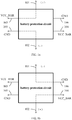
- FIG. 1a and FIG. 1b relate to functional schematic diagrams of a battery protection circuit according to an embodiment.
- the battery protection circuit 10 includes a first connecting end 101, a second connecting end 102, a third connecting end 103, a fourth connecting end 104, a fifth connecting end 105, and a sixth connecting end 106.
- the battery protection circuit 10 is configured for connecting with a battery.
- the third connecting end 103 and the fourth connecting end 104 are both configured for connecting with a positive voltage terminal VCC_BAR, the fifth connecting end 105 and the sixth connecting end 106 are both configured for connecting with ground terminal GND.
- FIG. 2 shows a block diagram of a battery protection circuit according to an embodiment.
- the battery protection circuit 10 is configured for connecting with a battery 90.
- the first connecting end 101 is connected to one end of the battery 90, and the second connecting end 102 is connected to the other end of the battery 90.
- the battery protection circuit 10 includes a first switch unit 110, a second switch unit 120, a third switch unit 130, and a fourth switch unit 140, wherein each switch unit has three ends.
- the three ends of each switch unit include a first end A, a second end B, and a control end C.
- the turning on or off between the first end A and the second end B is controlled according to the voltage level applied on the control end C.
- the first switch unit 110 and the fourth switch unit 140 are controlled to be turned on under a high-level voltage, and controlled to be turned off under a low-level voltage.
- the second switch unit 120 and the third switch unit 130 are controlled to be turned on under a low-level voltage, and controlled to be turned off under a high-level voltage.
- the first end A of the first switch unit 110 acts as the third connecting end 103 and is connected to the positive voltage terminal VCC_BAR, the second end B and the control end C of the first switch unit 110 are both connected to the first connecting end 101.
- the first end A of the second switch unit 120 acts as the sixth connecting end 106 and is connected to the ground terminal GND, the second end B and the control end C of the second switch unit 120 are both connected to the first connecting end 101.
- the first end A of the third switch unit 130 acts as the fifth connecting end 105 and is connected to the ground terminal GND, the second end B and the control end C of the third switch unit 130 are both connected to the second connecting end 102.
- the first end A of the fourth switch unit 140 acts as the fourth connecting end 104 and is connected to the positive voltage terminal VCC_BAR, the second end B and the control end C of the fourth switch unit 140 are both connected to the second connecting end 102.
- the first switch unit 110 When the positive electrode of the battery 90 is connected to the first connecting end 101 and the negative electrode of the battery 90 is connected to the second connecting end 102, the first switch unit 110 is turned on due to a high potential applied on the control end C of the first switch unit 110, the second switch unit 120 is turned off due to a high potential applied on the control end C of the second switch unit 120, the third switch unit 130 is turned on due to a low potential applied on the control end C of the third switch unit 130, and the fourth switch unit 140 is turned off due to a low potential applied on the control end C of the fourth switch unit 140. Therefore, the battery 90 outputs voltage through the first switch unit 110 and the third switch unit 130, i.e., the battery 90 outputs voltage through the third connecting end 103 and the fifth connecting end 105.
- the first switch unit 110 is turned off due to a low potential applied on the control end C of the first switch unit 110
- the second switch unit 120 is turned on due to a low potential applied on the control end C of the second switch unit 120
- the third switch unit 130 is turned off due to a high potential applied on the control end C of the third switch unit 130
- the fourth switch unit 140 is turned on due to a high potential applied on the control end C of the fourth switch unit 140. Therefore, the battery 90 outputs voltage through the second switch unit 120 and the fourth switch unit 140, i.e., the battery 90 outputs voltage through the fourth connecting end 104 and the sixth connecting end 106.
- the first switch unit 110 and the fourth switch unit 140 may both be NMOS transistors, wherein the first end A is a source terminal S, the second end B is a drain terminal D, and the control end C is a gate terminal G.
- the second switch unit 120 and the third switch unit 130 may both be PMOS transistors, wherein the first end A is a source terminal S, the second end B is a drain terminal D, and the control end C is a gate terminal G.
- each of the first switch unit 110 and the fourth switch unit 140 adopts an AON6512 chip, wherein the 1 st to 3 rd pins of the AON6512 chip of the first switch unit 110 are led out for acting as the third connecting end 103 and connecting with the positive voltage terminal VCC_BAR, the 4 th to 8 th pins of the AON6512 chip of the first switch unit 110 are connected to the first connecting end 101, the 1 st to 3 rd pins of the AON6512 chip of the fourth switch unit 140 are led out for acting as the fourth connecting end 104 and connecting with the positive voltage terminal VCC_BAR, and the 4 th to 8 th pins of the AON6512 chip of the fourth switch unit 140 are connected to the second connecting end 102.
- Each of the second switch unit 120 and the third switch unit 130 adopts an AON6411 chip, wherein the 1 st to 3 rd pins of the AON6411 chip of the second switch unit 120 are led out for acting as the sixth connecting end 106 and connecting with the ground terminal GND, the 4 th to 8 th pins of the AON6411 chip of the second switch unit 120 are connected to the first connecting end 101, the 1 st to 3 rd pins of the AON6411 chip of the third switch unit 130 are led out for acting as the fifth connecting end 105 and connecting with the ground terminal GND, and the 4 th to 8 th pins of the AON6411 chip of the third switch unit 130 are connected to the second connecting end 102.
- FIG. 5 shows a block diagram of a battery protection circuit according to another embodiment.
- the battery protection circuit 10 includes a first relay switch module 210 and a second relay switch module 220.
- the first relay switch module 210 includes a first coil 211 and a first switch 212
- the second relay switch module 220 includes a second coil 221 and a second switch 222.
- the normally opened contact of the first switch 212 acts as the third connecting end 103 and is connected to the positive voltage terminal VCC_BAR
- the normally closed contact of the first switch 212 acts as the sixth connecting end 106 and is connected to the ground terminal GND
- the common contact of the first switch 212 is connected to the first connecting end 101.
- the normally opened contact of the second switch 222 acts as the fifth connecting end 105 and is connected to the ground terminal GND
- the normally closed contact of the second switch 222 acts as the fourth connecting end 104 and is connected to the positive voltage terminal VCC_BAR
- the common contact of the second switch 222 is connected to the second connecting end 102.
- the first connecting end 101 is connected to the first coil 211 and the second coil 221 via a first anti-reverse diode D1, and the positive terminal of the first anti-reverse diode D1 is connected to the first connecting end 101.
- the first coil 211 is magnetically coupled to the first switch 212
- the second coil 221 is magnetically coupled to the second switch 222. Further, in actual implementations, the first coil 211 is located adjacent to the normally opened contact of the first switch 212. Similarly, the second coil 221 is located adjacent to the normally opened contact of the second switch 222.
- the electrical current flows through the first anti-reverse diode D1 from the first connecting end 101 (i.e., the positive electrode of the battery) to the first coil 211 and the second coil 221, and finally flows back to the second connecting end 102 (i.e., the negative electrode of the battery), to form a loop.
- An electromagnetic induction is generated when the electrical current flows through the first coil 211, so as to attract the spring sheet of the first switch 212 to the normally opened contact, whereby the first relay switch module 210 connects the positive electrode of the battery with the positive voltage terminal VCC_BAR through the third connecting end 103.
- the first connecting end 101 When the first connecting end 101 is connected to the negative electrode of the battery and the second connecting end 102 is connected to the positive electrode of the battery, the electrical current cannot flow to the first coil 211 and the second coil 221 through the first anti-reverse diode D1.
- the spring sheet of the first switch 212 remains in the normally closed state. Therefore, the first relay switch module 210 connects the negative electrode of the battery with the ground terminal GND through the sixth connecting end 106. At the same time, the spring sheet of the second switch 222 remains in the normally closed state. Therefore, the second relay switch module 220 connects the positive electrode of the battery with the positive voltage terminal VCC_BAR through the fourth connecting end 104.
- the aforementioned battery protection circuit 10 can be applied to an electronic cigarette or other electronic devices.
- An electronic cigarette according to an embodiment is provided as follows.
- an electronic cigarette includes the aforementioned battery protection circuit 10, a master control circuit 20, and an atomizing circuit 30.
- the battery protection circuit 10 is configured for connecting with a battery 90 so as to provide power for the master control circuit 20 and the atomizing circuit 30.
- the electronic cigarette can further include a battery 90.
- the positive electrode of the battery 90 is connected to the first connecting end 101 of the battery protection circuit 10, and the negative electrode of the battery 90 is connected to the second connecting end 102 of the battery protection circuit 10.
- the positive electrode of the battery 90 is connected to the second connecting end 102 of the battery protection circuit 10, and the negative electrode of the battery 90 is connected to the first connecting end 101 of the battery protection circuit 10.
- the battery protection circuit 10 can provide power for the electronic cigarette when the positive electrode and the negative electrode of the battery 90 are connected in any ways.
- the battery 90 is detachably or fixedly connected to the battery protection circuit 10.
- the detachable connection is suitable for replaceable battery, and the aforementioned battery protection circuit 10 can prevent the user from assembling the battery reversely.
- the fixed connection is suitable for the situation that a replacement of the battery is not permitted, and the aforementioned battery protection circuit 10 can prevent a reverse assembly of the battery in the production process, to thereby improve an assembling efficiency.
- the battery 90 can be a rechargeable battery.
- the rechargeable battery is suitable for being detachably or fixedly connected in the electronic cigarette.
- the electronic cigarette can further include a receiving case 40 and a battery case 50.
- the battery case 50 is configured for receiving the battery 90.
- the battery case 50 forms two first interfaces 501, 502 which are the same as each other, wherein the two first interfaces 501, 502 are respectively led out to an outside of the battery case 50 from the positive electrode and the negative electrode of the battery 90.
- the receiving case 40 is connected to the first connecting end 101 and the second connecting end 102 of the battery protection circuit 10.
- the receiving case 40 forms two second interfaces 401, 402 which are the same as each other, wherein the two second interfaces 401, 402 are respectively led out from the first connecting end 101 and the second connecting end 102 into an interior of the receiving case 40.
- the battery case 50 is received in the receiving case 40, and the first interfaces 501, 502 of the battery case 50 are connected to the second interfaces 401, 402 of the receiving case 40.
- the battery can be a button cell or a cylinder battery. Accordingly, the battery case 50 has a shape and a structure that suitable for receiving the button cell or the cylinder battery.
- the battery case 50 has an inner structure adaptable for the positive electrode and the negative electrode of the battery, and the outer structure of the battery case 50 has a commonly used shape and structure.
- the battery case 50 is assembled into the receiving case 40, it is not required to consider the direction of assembling, the assembling process is simple and convenient.
Landscapes
- Engineering & Computer Science (AREA)
- Power Engineering (AREA)
- Chemical & Material Sciences (AREA)
- Chemical Kinetics & Catalysis (AREA)
- Electrochemistry (AREA)
- General Chemical & Material Sciences (AREA)
- Charge And Discharge Circuits For Batteries Or The Like (AREA)
Abstract
Description
- The present application relates to the technical field of smoking simulation, and more particularly, to an electronic cigarette and a battery protection circuit of the electronic cigarette.
- Conventional electronic cigarettes can be powered on to work only if a battery is installed properly in a forward direction. When the battery is installed reversely, the electronic cigarette is powered off and cannot work, and the battery may be burned out immediately if a USB (Universal Serial Bus) wire is plugged to the electronic cigarette for charging the battery. For the electronic cigarette having a replaceable battery or having a non-replaceable battery, in order to avoid a reverse assembly of the battery, the user and the producer should be cautious when assembling the battery. Particularly for the electronic cigarette having the replaceable battery, if the user assembles the battery in a dark or poor lighting environment, the battery may be assembled reversely, causing the battery or the product to be damaged due to a reverse assembly.
- Accordingly, it is necessary to provide a battery protection circuit that can provide voltage output or voltage input when the battery is installed either in a forward direction or in a reverse direction, so as to protect the battery and the circuit.
- Further, an electronic cigarette is also provided.
- A battery protection circuit is configured for connecting with a battery. The battery protection circuit includes a first connecting end and a second connecting end. The first connecting end is configured for connecting with an electrode of the battery, and the second connecting end is configured for connecting with an opposite electrode of the battery. The battery protection circuit further includes a third connecting end, a fourth connecting end, a fifth connecting end and a sixth connecting end. The third connecting end and the fourth connecting end are both configured for connecting with a positive voltage terminal. The fifth connecting end and the sixth connecting end are both configured for connecting with the ground terminal.
- When the first connecting end is connected to the positive electrode of the battery and the second connecting end is connected to the negative electrode of the battery, the third connecting end is in connection with the first connecting end and the fifth connecting end is in connection with the second connecting end.
- When the first connecting end is connected to the negative electrode of the battery and the second connecting end is connected to the positive electrode of the battery, the sixth connecting end is in connection with the first connecting end and the fourth connecting end is in connection with the second connecting end.
- In one embodiment, the battery protection circuit includes a first switch unit, a second switch unit, a third switch unit and a fourth switch unit. Each switch unit has three ends, the three ends of each switch unit are comprised of a first end, a second end and a control end. The turning on or off between the first end and the second end is controlled according to the voltage level applied on the control end. The first switch unit and the fourth switch unit are controlled to be turned on under a high-level voltage, and controlled to be turned off under a low-level voltage. The second switch unit and the third switch unit are controlled to be turned on under a low-level voltage, and controlled to be turned off under a high-level voltage.
- For the first switch unit, the first end acts as the third connecting end and is connected to the positive voltage terminal, the second end and the control end are both connected to the first connecting end.
- For the second switch unit, the first end acts as the sixth connecting end and is connected to the ground terminal, the second end and the control end are both connected to the first connecting end.
- For the third switch unit, the first end acts as the fifth connecting end and is connected to the ground terminal, the second end and the control end are both connected to the second connecting end.
- For the fourth switch unit, the first end acts as the fourth connecting end and is connected to the positive voltage terminal, the second end and the control end are both connected to the second connecting end.
- In one embodiment, both the first switch unit and the fourth switch unit are NMOS transistors, the first end is a source terminal, the second end is a drain terminal, and the control end is a gate terminal. Both the second switch unit and the third switch unit are PMOS transistors, the first end is a source terminal, the second end is a drain terminal, and the control end is a gate terminal.
- In one embodiment, each of the first switch unit and the fourth switch unit adopts an AON6512 chip. The 1st to 3rd pins of the AON6512 chip of the first switch unit are led out for acting as the third connecting end and connecting with the positive voltage terminal, and the 4th to 8th pins of the AON6512 chip of the first switch unit are connected to the first connecting end. The 1st to 3rd pins of the AON6512 chip of the fourth switch unit are led out for acting as the fourth connecting end and connecting with the positive voltage terminal, and the 4th to 8th pins of the AON6512 chip of the fourth switch unit are connected to the second connecting end.
- Each of the second switch unit and the third switch unit adopts an AON6411 chip. The 1st to 3rd pins of the AON6411 chip of the second switch unit are led out for acting as the sixth connecting end and connecting with the ground terminal, and the 4th to 8th pins of the AON6411 chip of the second switch unit are connected to the first connecting end. The 1st to 3rd pins of the AON6411 chip of the third switch unit are led out for acting as the fifth connecting end and connecting with the ground terminal, and the 4th to 8th pins of the AON6411 chip of the third switch unit are connected to the second connecting end.
- In one embodiment, the battery protection circuit includes a first relay switch module and a second relay switch module. The first relay switch module includes a first coil and a first switch. The second relay switch module includes a second coil and a second switch.
- Two ends of the first coil are connected to the first connecting end and the second connecting end, respectively. The normally opened contact of the first switch acts as the third connecting end and is connected to the positive voltage terminal, the normally closed contact of the first switch acts as the sixth connecting end and is connected to the ground terminal, and the common contact of the first switch is connected to the first connecting end.
- Two ends of the second coil are connected to the first connecting end and the second connecting end, respectively. The normally opened contact of the second switch acts as the fifth connecting end and is connected to the ground terminal, the normally closed contact of the second switch acts as the fourth connecting end and is connected to the positive voltage terminal, and the common contact of the second switch is connected to the second connecting end.
- The first connecting end is connected to the first coil and the second coil via a first anti-reverse diode, and the positive terminal of the first anti-reverse diode is connected to the first connecting end.
- An electronic cigarette includes a master control circuit, an atomizing circuit, and the foregoing battery protection circuit. The battery protection circuit is configured for connecting with a battery so as to provide power for the master control circuit and the atomizing circuit.
- In one embodiment, the electronic cigarette further includes a battery. The positive electrode of the battery is connected to the first connecting end of the battery protection circuit, and the negative electrode of the battery is connected to the second connecting end of the battery protection circuit. Or, the positive electrode of the battery is connected to the second connecting end of the battery protection circuit, and the negative electrode of the battery is connected to the first connecting end of the battery protection circuit.
- In one embodiment, the battery is detachably or fixedly connected to the battery protection circuit.
- In one embodiment, the battery is a rechargeable battery.
- In one embodiment, the electronic cigarette further includes a receiving case and a battery case. The battery case is configured for receiving the battery. The battery case forms two first interfaces which are the same as each other, the two first interfaces are respectively led out to an outside of battery case from the positive electrode and the negative electrode of the battery. The receiving case is connected to the first connecting end and the second connecting end of the battery protection circuit. The receiving case forms two second interfaces which are the same as each other, the two second interfaces are respectively led out from the first connecting end and the second connecting end into an interior of the receiving case. The battery case is received in the receiving case and the first interfaces are connected to the second interfaces.
- In the foregoing electronic cigarette and the foregoing battery protection circuit, when the positive electrode of the battery is connected to the first connecting end and the negative electrode of the battery is connected to the second connecting end, the first switch unit is turned on due to a high potential applied on the control end C of the first switch unit, the second switch unit is turned off due to a high potential applied on the control end C of the second switch unit, the third switch unit is turned on due to a low potential applied on the control end C of the third switch unit, and the fourth switch unit is turned off due to a low potential applied on the control end C of the fourth switch unit. Therefore, the battery outputs voltage through the first switch unit and the third switch unit.
- When the negative electrode of the battery is connected to the first connecting end and the positive electrode of the battery is connected to the second connecting end, the first switch unit is turned off due to a low potential applied on the control end C of the first switch unit, the second switch unit is turned on due to a low potential applied on the control end C of the second switch unit, the third switch unit is turned off due to a high potential applied on the control end C of the third switch unit, and the fourth switch unit is turned on due to a high potential applied on the control end C of the fourth switch unit. Therefore, the battery outputs voltage through the second switch unit and the fourth switch unit. As a result, the battery can provide power for the electronic cigarette no matter how the battery is installed, to effectively prevent inverse connection.
-
-
FIG. 1a and FIG. 1b are functional schematic diagrams of a battery protection circuit according to an embodiment; -
FIG. 2 is a block diagram of a battery protection circuit according to an embodiment; -
FIG. 3 is a circuit diagram when the switch units inFIG. 2 adopt MOS transistors; -
FIG. 4 is a circuit diagram when the switch units inFIG. 2 adopt chips; -
FIG. 5 is a block diagram of a battery protection circuit according to another embodiment; -
FIG. 6 is a block diagram of an electronic cigarette according to an embodiment; -
FIG. 7 is a schematic diagram of a battery case and a receiving case. - Embodiments of the disclosure are described more fully hereinafter with reference to the accompanying drawings.
-
FIG. 1a and FIG. 1b relate to functional schematic diagrams of a battery protection circuit according to an embodiment. Thebattery protection circuit 10 includes a first connectingend 101, a secondconnecting end 102, a thirdconnecting end 103, a fourth connectingend 104, a fifth connectingend 105, and a sixth connectingend 106. Thebattery protection circuit 10 is configured for connecting with a battery. - The third
connecting end 103 and the fourth connectingend 104 are both configured for connecting with a positive voltage terminal VCC_BAR, the fifth connectingend 105 and the sixth connectingend 106 are both configured for connecting with ground terminal GND. - As shown in
FIG. 1a , when the first connectingend 101 is connected to the positive electrode (+) of the battery and the second connectingend 102 is connected to the negative electrode (-) of the battery, the third connectingend 103 is in connection with the first connectingend 101 and the fifth connectingend 105 is in connection with the second connectingend 102. - As shown in
FIG. 1b , when the first connectingend 101 is connected to the negative electrode (-) of the battery and the second connectingend 102 is connected to the positive electrode (+) of the battery, the sixth connectingend 106 is in connection with the first connectingend 101 and the fourth connectingend 104 is in connection with the second connectingend 102. -
FIG. 2 shows a block diagram of a battery protection circuit according to an embodiment. Thebattery protection circuit 10 is configured for connecting with abattery 90. The first connectingend 101 is connected to one end of thebattery 90, and the second connectingend 102 is connected to the other end of thebattery 90. - The
battery protection circuit 10 includes afirst switch unit 110, asecond switch unit 120, athird switch unit 130, and afourth switch unit 140, wherein each switch unit has three ends. The three ends of each switch unit include a first end A, a second end B, and a control end C. The turning on or off between the first end A and the second end B is controlled according to the voltage level applied on the control end C. Thefirst switch unit 110 and thefourth switch unit 140 are controlled to be turned on under a high-level voltage, and controlled to be turned off under a low-level voltage. Thesecond switch unit 120 and thethird switch unit 130 are controlled to be turned on under a low-level voltage, and controlled to be turned off under a high-level voltage. - As shown in
FIG. 2 , the first end A of thefirst switch unit 110 acts as the third connectingend 103 and is connected to the positive voltage terminal VCC_BAR, the second end B and the control end C of thefirst switch unit 110 are both connected to the first connectingend 101. The first end A of thesecond switch unit 120 acts as the sixth connectingend 106 and is connected to the ground terminal GND, the second end B and the control end C of thesecond switch unit 120 are both connected to the first connectingend 101. - The first end A of the
third switch unit 130 acts as the fifth connectingend 105 and is connected to the ground terminal GND, the second end B and the control end C of thethird switch unit 130 are both connected to the second connectingend 102. The first end A of thefourth switch unit 140 acts as the fourth connectingend 104 and is connected to the positive voltage terminal VCC_BAR, the second end B and the control end C of thefourth switch unit 140 are both connected to the second connectingend 102. - When the positive electrode of the
battery 90 is connected to the first connectingend 101 and the negative electrode of thebattery 90 is connected to the second connectingend 102, thefirst switch unit 110 is turned on due to a high potential applied on the control end C of thefirst switch unit 110, thesecond switch unit 120 is turned off due to a high potential applied on the control end C of thesecond switch unit 120, thethird switch unit 130 is turned on due to a low potential applied on the control end C of thethird switch unit 130, and thefourth switch unit 140 is turned off due to a low potential applied on the control end C of thefourth switch unit 140. Therefore, thebattery 90 outputs voltage through thefirst switch unit 110 and thethird switch unit 130, i.e., thebattery 90 outputs voltage through the third connectingend 103 and the fifth connectingend 105. - When the negative electrode of the
battery 90 is connected to the first connectingend 101 and the positive electrode of thebattery 90 is connected to the second connectingend 102, thefirst switch unit 110 is turned off due to a low potential applied on the control end C of thefirst switch unit 110, thesecond switch unit 120 is turned on due to a low potential applied on the control end C of thesecond switch unit 120, thethird switch unit 130 is turned off due to a high potential applied on the control end C of thethird switch unit 130, and thefourth switch unit 140 is turned on due to a high potential applied on the control end C of thefourth switch unit 140. Therefore, thebattery 90 outputs voltage through thesecond switch unit 120 and thefourth switch unit 140, i.e., thebattery 90 outputs voltage through the fourth connectingend 104 and the sixth connectingend 106. - In one embodiment, as shown in
FIG. 3 , thefirst switch unit 110 and thefourth switch unit 140 may both be NMOS transistors, wherein the first end A is a source terminal S, the second end B is a drain terminal D, and the control end C is a gate terminal G. Thesecond switch unit 120 and thethird switch unit 130 may both be PMOS transistors, wherein the first end A is a source terminal S, the second end B is a drain terminal D, and the control end C is a gate terminal G. - In one embodiment, as shown in
FIG. 4 , each of thefirst switch unit 110 and thefourth switch unit 140 adopts an AON6512 chip, wherein the 1st to 3rd pins of the AON6512 chip of thefirst switch unit 110 are led out for acting as the third connectingend 103 and connecting with the positive voltage terminal VCC_BAR, the 4th to 8th pins of the AON6512 chip of thefirst switch unit 110 are connected to the first connectingend 101, the 1st to 3rd pins of the AON6512 chip of thefourth switch unit 140 are led out for acting as the fourth connectingend 104 and connecting with the positive voltage terminal VCC_BAR, and the 4th to 8th pins of the AON6512 chip of thefourth switch unit 140 are connected to the second connectingend 102. Each of thesecond switch unit 120 and thethird switch unit 130 adopts an AON6411 chip, wherein the 1st to 3rd pins of the AON6411 chip of thesecond switch unit 120 are led out for acting as the sixth connectingend 106 and connecting with the ground terminal GND, the 4th to 8th pins of the AON6411 chip of thesecond switch unit 120 are connected to the first connectingend 101, the 1st to 3rd pins of the AON6411 chip of thethird switch unit 130 are led out for acting as the fifth connectingend 105 and connecting with the ground terminal GND, and the 4th to 8th pins of the AON6411 chip of thethird switch unit 130 are connected to the second connectingend 102. -
FIG. 5 shows a block diagram of a battery protection circuit according to another embodiment. Thebattery protection circuit 10 includes a firstrelay switch module 210 and a secondrelay switch module 220. The firstrelay switch module 210 includes afirst coil 211 and afirst switch 212, and the secondrelay switch module 220 includes asecond coil 221 and asecond switch 222. - Two ends of the
first coil 211 are connected to the first connectingend 101 and the second connectingend 102, respectively. The normally opened contact of thefirst switch 212 acts as the third connectingend 103 and is connected to the positive voltage terminal VCC_BAR, the normally closed contact of thefirst switch 212 acts as the sixth connectingend 106 and is connected to the ground terminal GND, and the common contact of thefirst switch 212 is connected to the first connectingend 101. - Two ends of the
second coil 221 are connected to the first connectingend 101 and the second connectingend 102, respectively. The normally opened contact of thesecond switch 222 acts as the fifth connectingend 105 and is connected to the ground terminal GND, the normally closed contact of thesecond switch 222 acts as the fourth connectingend 104 and is connected to the positive voltage terminal VCC_BAR, and the common contact of thesecond switch 222 is connected to the second connectingend 102. - The first connecting
end 101 is connected to thefirst coil 211 and thesecond coil 221 via a first anti-reverse diode D1, and the positive terminal of the first anti-reverse diode D1 is connected to the first connectingend 101. - The
first coil 211 is magnetically coupled to thefirst switch 212, and thesecond coil 221 is magnetically coupled to thesecond switch 222. Further, in actual implementations, thefirst coil 211 is located adjacent to the normally opened contact of thefirst switch 212. Similarly, thesecond coil 221 is located adjacent to the normally opened contact of thesecond switch 222. - When the first connecting
end 101 is connected to the positive electrode of the battery and the second connectingend 102 is connected to the negative electrode of the battery, the electrical current flows through the first anti-reverse diode D1 from the first connecting end 101 (i.e., the positive electrode of the battery) to thefirst coil 211 and thesecond coil 221, and finally flows back to the second connecting end 102 (i.e., the negative electrode of the battery), to form a loop. An electromagnetic induction is generated when the electrical current flows through thefirst coil 211, so as to attract the spring sheet of thefirst switch 212 to the normally opened contact, whereby the firstrelay switch module 210 connects the positive electrode of the battery with the positive voltage terminal VCC_BAR through the third connectingend 103. At the same time, an electromagnetic induction is generated when the electrical current flows through thesecond coil 221, so as to attract the spring sheet of thesecond switch 222 to the normally opened contact, whereby the secondrelay switch module 220 connects the negative electrode of the battery with the ground terminal GND through the fifth connectingend 105. - When the first connecting
end 101 is connected to the negative electrode of the battery and the second connectingend 102 is connected to the positive electrode of the battery, the electrical current cannot flow to thefirst coil 211 and thesecond coil 221 through the first anti-reverse diode D1. The spring sheet of thefirst switch 212 remains in the normally closed state. Therefore, the firstrelay switch module 210 connects the negative electrode of the battery with the ground terminal GND through the sixth connectingend 106. At the same time, the spring sheet of thesecond switch 222 remains in the normally closed state. Therefore, the secondrelay switch module 220 connects the positive electrode of the battery with the positive voltage terminal VCC_BAR through the fourth connectingend 104. - The aforementioned
battery protection circuit 10 can be applied to an electronic cigarette or other electronic devices. An electronic cigarette according to an embodiment is provided as follows. - As shown in
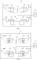
FIG. 6 , an electronic cigarette according to an embodiment includes the aforementionedbattery protection circuit 10, amaster control circuit 20, and anatomizing circuit 30. Thebattery protection circuit 10 is configured for connecting with abattery 90 so as to provide power for themaster control circuit 20 and theatomizing circuit 30. - The electronic cigarette can further include a
battery 90. The positive electrode of thebattery 90 is connected to the first connectingend 101 of thebattery protection circuit 10, and the negative electrode of thebattery 90 is connected to the second connectingend 102 of thebattery protection circuit 10. Or optionally, the positive electrode of thebattery 90 is connected to the second connectingend 102 of thebattery protection circuit 10, and the negative electrode of thebattery 90 is connected to the first connectingend 101 of thebattery protection circuit 10. Thebattery protection circuit 10 can provide power for the electronic cigarette when the positive electrode and the negative electrode of thebattery 90 are connected in any ways. - The
battery 90 is detachably or fixedly connected to thebattery protection circuit 10. The detachable connection is suitable for replaceable battery, and the aforementionedbattery protection circuit 10 can prevent the user from assembling the battery reversely. The fixed connection is suitable for the situation that a replacement of the battery is not permitted, and the aforementionedbattery protection circuit 10 can prevent a reverse assembly of the battery in the production process, to thereby improve an assembling efficiency. Thebattery 90 can be a rechargeable battery. The rechargeable battery is suitable for being detachably or fixedly connected in the electronic cigarette. - Further, as shown in
FIG. 7 , the electronic cigarette can further include a receivingcase 40 and abattery case 50. Thebattery case 50 is configured for receiving thebattery 90. Thebattery case 50 forms twofirst interfaces first interfaces battery case 50 from the positive electrode and the negative electrode of thebattery 90. The receivingcase 40 is connected to the first connectingend 101 and the second connectingend 102 of thebattery protection circuit 10. The receivingcase 40 forms twosecond interfaces second interfaces end 101 and the second connectingend 102 into an interior of the receivingcase 40. Thebattery case 50 is received in the receivingcase 40, and thefirst interfaces battery case 50 are connected to thesecond interfaces case 40. The battery can be a button cell or a cylinder battery. Accordingly, thebattery case 50 has a shape and a structure that suitable for receiving the button cell or the cylinder battery. - By the aforementioned structure, the
battery case 50 has an inner structure adaptable for the positive electrode and the negative electrode of the battery, and the outer structure of thebattery case 50 has a commonly used shape and structure. When thebattery case 50 is assembled into the receivingcase 40, it is not required to consider the direction of assembling, the assembling process is simple and convenient. - Various technical features of the above embodiments can be combined in any manner. For clarity, all possible combinations of the various technical features of the above embodiments are not described. However, as long as combinations of these technical features do not contradict with each other, they should be regarded within the scope described in the present specification.
- The embodiments described above are merely preferred embodiments, but not intended to limit the application. Any modifications, alternatives or improvements made within the principle of the present application should be interpreted as falling within the protection scope of the present application. The claims are not limited to the features or acts described above. Rather, the proper scope of the application is defined by the appended claims.
Claims (10)
- A battery protection circuit configured for connecting with a battery, the battery protection circuit comprising a first connecting end and a second connecting end, the first connecting end being configured for connecting with an electrode of the battery, the second connecting end being configured for connecting with an opposite electrode of the battery; wherein the battery protection circuit further comprises a third connecting end, a fourth connecting end, a fifth connecting end and a sixth connecting end; the third connecting end and the fourth connecting end are both configured for connecting with a positive voltage terminal, the fifth connecting end and the sixth connecting end are both configured for connecting with the ground terminal;when the first connecting end is connected to the positive electrode of the battery and the second connecting end is connected to the negative electrode of the battery, the third connecting end is in connection with the first connecting end and the fifth connecting end is in connection with the second connecting end;when the first connecting end is connected to the negative electrode of the battery and the second connecting end is connected to the positive electrode of the battery, the sixth connecting end is in connection with the first connecting end and the fourth connecting end is in connection with the second connecting end.
- The battery protection circuit according to claim 1, wherein the battery protection circuit comprises a first switch unit, a second switch unit, a third switch unit and a fourth switch unit, each switch unit has three ends, the three ends of each switch unit are comprised of a first end, a second end and a control end, the turning on or off between the first end and the second end is controlled according to the voltage level applied on the control end; the first switch unit and the fourth switch unit are controlled to be turned on under a high-level voltage, and controlled to be turned off under a low-level voltage; the second switch unit and the third switch unit are controlled to be turned on under a low-level voltage, and controlled to be turned off under a high-level voltage;for the first switch unit, the first end acts as the third connecting end and is connected to the positive voltage terminal, the second end and the control end are both connected to the first connecting end;for the second switch unit, the first end acts as the sixth connecting end and is connected to the ground terminal, the second end and the control end are both connected to the first connecting end;for the third switch unit, the first end acts as the fifth connecting end and is connected to the ground terminal, the second end and the control end are both connected to the second connecting end;for the fourth switch unit, the first end acts as the fourth connecting end and is connected to the positive voltage terminal, the second end and the control end are both connected to the second connecting end.
- The battery protection circuit according to claim 2, wherein both the first switch unit and the fourth switch unit are NMOS transistors, the first end is a source terminal, the second end is a drain terminal, and the control end is a gate terminal; both the second switch unit and the third switch unit are PMOS transistors, the first end is a source terminal, the second end is a drain terminal, and the control end is a gate terminal.
- The battery protection circuit according to claim 3, wherein each of the first switch unit and the fourth switch unit adopts an AON6512 chip, wherein the 1st to 3rd pins of the AON6512 chip of the first switch unit are led out for acting as the third connecting end and connecting with the positive voltage terminal, and the 4th to 8th pins of the AON6512 chip of the first switch unit are connected to the first connecting end; the 1st to 3rd pins of the AON6512 chip of the fourth switch unit are led out for acting as the fourth connecting end and connecting with the positive voltage terminal, and the 4th to 8th pins of the AON6512 chip of the fourth switch unit are connected to the second connecting end;
each of the second switch unit and the third switch unit adopts an AON6411 chip, wherein the 1st to 3rd pins of the AON6411 chip of the second switch unit are led out for acting as the sixth connecting end and connecting with the ground terminal, and the 4th to 8th pins of the AON6411 chip of the second switch unit are connected to the first connecting end; the 1st to 3rd pins of the AON6411 chip of the third switch unit are led out for acting as the fifth connecting end and connecting with the ground terminal, and the 4th to 8th pins of the AON6411 chip of the third switch unit are connected to the second connecting end. - The battery protection circuit according to claim 1, wherein the battery protection circuit comprises a first relay switch module and a second relay switch module, the first relay switch module comprises a first coil and a first switch, the second relay switch module comprises a second coil and a second switch;two ends of the first coil are connected to the first connecting end and the second connecting end, respectively; the normally opened contact of the first switch acts as the third connecting end and is connected to the positive voltage terminal, the normally closed contact of the first switch acts as the sixth connecting end and is connected to the ground terminal, and the common contact of the first switch is connected to the first connecting end;two ends of the second coil are connected to the first connecting end and the second connecting end, respectively; the normally opened contact of the second switch acts as the fifth connecting end and is connected to the ground terminal, the normally closed contact of the second switch acts as the fourth connecting end and is connected to the positive voltage terminal, and the common contact of the second switch is connected to the second connecting end;the first connecting end is connected to the first coil and the second coil via a first anti-reverse diode, and the positive terminal of the first anti-reverse diode is connected to the first connecting end.
- An electronic cigarette comprising a master control circuit, an atomizing circuit and a battery protection circuit according to any one of claims 1 to 5, wherein the battery protection circuit is configured for connecting with a battery so as to provide power for the master control circuit and the atomizing circuit.
- The electronic cigarette according to claim 6, further comprising a battery, wherein the positive electrode of the battery is connected to the first connecting end of the battery protection circuit, and the negative electrode of the battery is connected to the second connecting end of the battery protection circuit; or, the positive electrode of the battery is connected to the second connecting end of the battery protection circuit, and the negative electrode of the battery is connected to the first connecting end of the battery protection circuit.
- The electronic cigarette according to claim 6, wherein the battery is detachably or fixedly connected to the battery protection circuit.
- The electronic cigarette according to claim 6, wherein the battery is a rechargeable battery.
- The electronic cigarette according to claim 6, further comprising a receiving case and a battery case, wherein the battery case is configured for receiving the battery, the battery case forms two first interfaces which are the same as each other, the two first interfaces are respectively led out to an outside of battery case from the positive electrode and the negative electrode of the battery, the receiving case is connected to the first connecting end and the second connecting end of the battery protection circuit, the receiving case forms two second interfaces which are the same as each other, the two second interfaces are respectively led out from the first connecting end and the second connecting end into an interior of the receiving case; the battery case is received in the receiving case and the first interfaces are connected to the second interfaces.
Applications Claiming Priority (2)
| Application Number | Priority Date | Filing Date | Title |
|---|---|---|---|
| CN201710025393.5A CN106655106A (en) | 2017-01-13 | 2017-01-13 | Electronic cigarette and battery protection circuit thereof |
| PCT/CN2017/107449 WO2018129979A1 (en) | 2017-01-13 | 2017-10-24 | Electronic cigarette and battery protection circuit thereof |
Publications (2)
| Publication Number | Publication Date |
|---|---|
| EP3570403A1 true EP3570403A1 (en) | 2019-11-20 |
| EP3570403A4 EP3570403A4 (en) | 2020-06-03 |
Family
ID=58843326
Family Applications (1)
| Application Number | Title | Priority Date | Filing Date |
|---|---|---|---|
| EP17891131.9A Withdrawn EP3570403A4 (en) | 2017-01-13 | 2017-10-24 | ELECTRONIC CIGARETTE AND ITS BATTERY PROTECTION CIRCUIT |
Country Status (4)
| Country | Link |
|---|---|
| US (1) | US20190356145A1 (en) |
| EP (1) | EP3570403A4 (en) |
| CN (2) | CN106655106A (en) |
| WO (1) | WO2018129979A1 (en) |
Families Citing this family (4)
| Publication number | Priority date | Publication date | Assignee | Title |
|---|---|---|---|---|
| CN106655106A (en) * | 2017-01-13 | 2017-05-10 | 常州市派腾电子技术服务有限公司 | Electronic cigarette and battery protection circuit thereof |
| CN113303504B (en) * | 2021-05-19 | 2023-08-22 | 西安稳先半导体科技有限责任公司 | Tobacco stem and electronic cigarette |
| CN115473011B (en) * | 2022-09-28 | 2024-06-21 | 维沃移动通信有限公司 | Electronic equipment |
| WO2026052730A1 (en) * | 2024-09-04 | 2026-03-12 | Jt International Sa | An aerosol generating device |
Family Cites Families (15)
| Publication number | Priority date | Publication date | Assignee | Title |
|---|---|---|---|---|
| DE10042583A1 (en) * | 2000-08-30 | 2002-03-28 | Infineon Technologies Ag | False polarity protection circuit with first and second input terminals for supply voltage and first and second output terminals for preparing an output voltage |
| US6784638B2 (en) * | 2003-01-24 | 2004-08-31 | Fu-I Yang | Series charger with separate detection of batteries |
| EP1498998A1 (en) * | 2003-07-16 | 2005-01-19 | Dialog Semiconductor GmbH | Protection switch with reverse voltage protection |
| CN201113409Y (en) * | 2007-09-20 | 2008-09-10 | 徐建华 | A polarity switching circuit for a charger |
| TWM334559U (en) * | 2008-01-17 | 2008-06-11 | ming-xiang Ye | Attached wireless charger |
| CN103516000A (en) * | 2012-06-15 | 2014-01-15 | 江苏金鼎汽车科技有限公司 | Polarity conversion circuit of charger |
| CN203491753U (en) * | 2013-10-14 | 2014-03-19 | 成都天宇创新科技有限公司 | Automatic polarity converter of vanadium cell |
| KR102721939B1 (en) * | 2013-12-23 | 2024-10-25 | 쥴 랩스, 인크. | Vaporization device systems and methods |
| CN104134990B (en) * | 2014-08-14 | 2017-08-04 | 惠州市新科华实业有限公司 | A kind of anti-short circuit protection system of emergency power supply |
| CN204146335U (en) * | 2014-09-24 | 2015-02-11 | 上海烟草集团有限责任公司 | A kind of electronic cigarette with secondary power supply |
| CN104485861A (en) * | 2014-09-26 | 2015-04-01 | 杨忠孝 | Intelligent DC position senseless photovoltaic pump drive controller |
| CN104333319B (en) * | 2014-11-10 | 2017-12-22 | 许继电气股份有限公司 | Input reverse-connection protection circuit for photovoltaic combining inverter |
| CN204292198U (en) * | 2014-11-20 | 2015-04-29 | 深圳市海派特光伏科技有限公司 | A kind of great-power electronic cigarette |
| CN205160498U (en) * | 2015-10-21 | 2016-04-13 | 天地融科技股份有限公司 | Reverse -connection -preventive circuit |
| CN106655106A (en) * | 2017-01-13 | 2017-05-10 | 常州市派腾电子技术服务有限公司 | Electronic cigarette and battery protection circuit thereof |
-
2017
- 2017-01-13 CN CN201710025393.5A patent/CN106655106A/en active Pending
- 2017-10-24 US US16/477,842 patent/US20190356145A1/en not_active Abandoned
- 2017-10-24 CN CN201790001563.XU patent/CN210273513U/en active Active
- 2017-10-24 EP EP17891131.9A patent/EP3570403A4/en not_active Withdrawn
- 2017-10-24 WO PCT/CN2017/107449 patent/WO2018129979A1/en not_active Ceased
Also Published As
| Publication number | Publication date |
|---|---|
| WO2018129979A1 (en) | 2018-07-19 |
| EP3570403A4 (en) | 2020-06-03 |
| CN210273513U (en) | 2020-04-07 |
| CN106655106A (en) | 2017-05-10 |
| US20190356145A1 (en) | 2019-11-21 |
Similar Documents
| Publication | Publication Date | Title |
|---|---|---|
| CN105790356B (en) | A kind of data line with charging circuit | |
| CN102709880B (en) | Module with optocoupler protection function | |
| US20190356145A1 (en) | Electronic cigarette and battery protection circuit thereof | |
| CN103260314A (en) | Short circuit protection circuit and electronic device with same | |
| CN115397079B (en) | Communication impedance matching circuit, lamp and lamp control system | |
| CN101604197B (en) | Power supply circuit of main board functional module | |
| CN102681963A (en) | Electronic equipment, charging or upgrading processing method thereof and charging or upgrading switching circuit thereof | |
| CN102231598B (en) | a power circuit | |
| CN103051325B (en) | Pull-up resistance circuit for preventing reverse current filling | |
| CN107231145B (en) | Reset unit and chip | |
| CN105576777B (en) | A kind of battery protection system | |
| CN107733413B (en) | A smart switch circuit and smart terminal with pre-installed battery system | |
| CN102811047B (en) | High voltage tolerant bus holder circuit and method of operating the circuit | |
| CN106849250A (en) | A kind of electronic equipment | |
| CN202257555U (en) | USB terminal | |
| US20150325960A1 (en) | Universal serial bus interface and mobile device | |
| CN104062917B (en) | A kind of terminal power-down circuit and mobile terminal | |
| CN220138200U (en) | Relay control circuit | |
| CN203772938U (en) | A power failure detection circuit for DC power supply | |
| CN216599036U (en) | Switching circuits, charging boxes and audio equipment | |
| CN102156502B (en) | Zero static power consumption circuit device for different voltage domains of analogue integrated circuit | |
| CN204349940U (en) | A kind of double edge trigger circuit | |
| CN105549722B (en) | Energy-saving control device | |
| CN220584677U (en) | TTL communication adapter of protection type sensor | |
| CN205142166U (en) | Switch delay circuit and bluetooth speaker of bluetooth chip |
Legal Events
| Date | Code | Title | Description |
|---|---|---|---|
| PUAI | Public reference made under article 153(3) epc to a published international application that has entered the european phase |
Free format text: ORIGINAL CODE: 0009012 |
|
| 17P | Request for examination filed |
Effective date: 20190808 |
|
| AK | Designated contracting states |
Kind code of ref document: A1 Designated state(s): AL AT BE BG CH CY CZ DE DK EE ES FI FR GB GR HR HU IE IS IT LI LT LU LV MC MK MT NL NO PL PT RO RS SE SI SK SM TR |
|
| AX | Request for extension of the european patent |
Extension state: BA ME |
|
| DAV | Request for validation of the european patent (deleted) | ||
| DAX | Request for extension of the european patent (deleted) | ||
| A4 | Supplementary search report drawn up and despatched |
Effective date: 20200506 |
|
| RIC1 | Information provided on ipc code assigned before grant |
Ipc: H02J 7/00 20060101AFI20200428BHEP |
|
| STAA | Information on the status of an ep patent application or granted ep patent |
Free format text: STATUS: THE APPLICATION HAS BEEN WITHDRAWN |
|
| 18W | Application withdrawn |
Effective date: 20200819 |