EP3570100A1 - Electrochromic cell - Google Patents
Electrochromic cell Download PDFInfo
- Publication number
- EP3570100A1 EP3570100A1 EP19174036.4A EP19174036A EP3570100A1 EP 3570100 A1 EP3570100 A1 EP 3570100A1 EP 19174036 A EP19174036 A EP 19174036A EP 3570100 A1 EP3570100 A1 EP 3570100A1
- Authority
- EP
- European Patent Office
- Prior art keywords
- layer
- electrochromic
- oxide
- film layer
- electrolyte
- Prior art date
- Legal status (The legal status is an assumption and is not a legal conclusion. Google has not performed a legal analysis and makes no representation as to the accuracy of the status listed.)
- Pending
Links
Images


Classifications
-
- G—PHYSICS
- G02—OPTICS
- G02F—OPTICAL DEVICES OR ARRANGEMENTS FOR THE CONTROL OF LIGHT BY MODIFICATION OF THE OPTICAL PROPERTIES OF THE MEDIA OF THE ELEMENTS INVOLVED THEREIN; NON-LINEAR OPTICS; FREQUENCY-CHANGING OF LIGHT; OPTICAL LOGIC ELEMENTS; OPTICAL ANALOGUE/DIGITAL CONVERTERS
- G02F1/00—Devices or arrangements for the control of the intensity, colour, phase, polarisation or direction of light arriving from an independent light source, e.g. switching, gating or modulating; Non-linear optics
- G02F1/01—Devices or arrangements for the control of the intensity, colour, phase, polarisation or direction of light arriving from an independent light source, e.g. switching, gating or modulating; Non-linear optics for the control of the intensity, phase, polarisation or colour
- G02F1/15—Devices or arrangements for the control of the intensity, colour, phase, polarisation or direction of light arriving from an independent light source, e.g. switching, gating or modulating; Non-linear optics for the control of the intensity, phase, polarisation or colour based on an electrochromic effect
- G02F1/1514—Devices or arrangements for the control of the intensity, colour, phase, polarisation or direction of light arriving from an independent light source, e.g. switching, gating or modulating; Non-linear optics for the control of the intensity, phase, polarisation or colour based on an electrochromic effect characterised by the electrochromic material, e.g. by the electrodeposited material
- G02F1/1523—Devices or arrangements for the control of the intensity, colour, phase, polarisation or direction of light arriving from an independent light source, e.g. switching, gating or modulating; Non-linear optics for the control of the intensity, phase, polarisation or colour based on an electrochromic effect characterised by the electrochromic material, e.g. by the electrodeposited material comprising inorganic material
- G02F1/1525—Devices or arrangements for the control of the intensity, colour, phase, polarisation or direction of light arriving from an independent light source, e.g. switching, gating or modulating; Non-linear optics for the control of the intensity, phase, polarisation or colour based on an electrochromic effect characterised by the electrochromic material, e.g. by the electrodeposited material comprising inorganic material characterised by a particular ion transporting layer, e.g. electrolyte
-
- G—PHYSICS
- G02—OPTICS
- G02F—OPTICAL DEVICES OR ARRANGEMENTS FOR THE CONTROL OF LIGHT BY MODIFICATION OF THE OPTICAL PROPERTIES OF THE MEDIA OF THE ELEMENTS INVOLVED THEREIN; NON-LINEAR OPTICS; FREQUENCY-CHANGING OF LIGHT; OPTICAL LOGIC ELEMENTS; OPTICAL ANALOGUE/DIGITAL CONVERTERS
- G02F1/00—Devices or arrangements for the control of the intensity, colour, phase, polarisation or direction of light arriving from an independent light source, e.g. switching, gating or modulating; Non-linear optics
- G02F1/01—Devices or arrangements for the control of the intensity, colour, phase, polarisation or direction of light arriving from an independent light source, e.g. switching, gating or modulating; Non-linear optics for the control of the intensity, phase, polarisation or colour
- G02F1/15—Devices or arrangements for the control of the intensity, colour, phase, polarisation or direction of light arriving from an independent light source, e.g. switching, gating or modulating; Non-linear optics for the control of the intensity, phase, polarisation or colour based on an electrochromic effect
- G02F1/1514—Devices or arrangements for the control of the intensity, colour, phase, polarisation or direction of light arriving from an independent light source, e.g. switching, gating or modulating; Non-linear optics for the control of the intensity, phase, polarisation or colour based on an electrochromic effect characterised by the electrochromic material, e.g. by the electrodeposited material
- G02F1/1523—Devices or arrangements for the control of the intensity, colour, phase, polarisation or direction of light arriving from an independent light source, e.g. switching, gating or modulating; Non-linear optics for the control of the intensity, phase, polarisation or colour based on an electrochromic effect characterised by the electrochromic material, e.g. by the electrodeposited material comprising inorganic material
- G02F1/1524—Transition metal compounds
-
- G—PHYSICS
- G02—OPTICS
- G02F—OPTICAL DEVICES OR ARRANGEMENTS FOR THE CONTROL OF LIGHT BY MODIFICATION OF THE OPTICAL PROPERTIES OF THE MEDIA OF THE ELEMENTS INVOLVED THEREIN; NON-LINEAR OPTICS; FREQUENCY-CHANGING OF LIGHT; OPTICAL LOGIC ELEMENTS; OPTICAL ANALOGUE/DIGITAL CONVERTERS
- G02F1/00—Devices or arrangements for the control of the intensity, colour, phase, polarisation or direction of light arriving from an independent light source, e.g. switching, gating or modulating; Non-linear optics
- G02F1/01—Devices or arrangements for the control of the intensity, colour, phase, polarisation or direction of light arriving from an independent light source, e.g. switching, gating or modulating; Non-linear optics for the control of the intensity, phase, polarisation or colour
- G02F1/15—Devices or arrangements for the control of the intensity, colour, phase, polarisation or direction of light arriving from an independent light source, e.g. switching, gating or modulating; Non-linear optics for the control of the intensity, phase, polarisation or colour based on an electrochromic effect
- G02F1/153—Constructional details
- G02F1/1533—Constructional details structural features not otherwise provided for
-
- G—PHYSICS
- G02—OPTICS
- G02F—OPTICAL DEVICES OR ARRANGEMENTS FOR THE CONTROL OF LIGHT BY MODIFICATION OF THE OPTICAL PROPERTIES OF THE MEDIA OF THE ELEMENTS INVOLVED THEREIN; NON-LINEAR OPTICS; FREQUENCY-CHANGING OF LIGHT; OPTICAL LOGIC ELEMENTS; OPTICAL ANALOGUE/DIGITAL CONVERTERS
- G02F1/00—Devices or arrangements for the control of the intensity, colour, phase, polarisation or direction of light arriving from an independent light source, e.g. switching, gating or modulating; Non-linear optics
- G02F1/01—Devices or arrangements for the control of the intensity, colour, phase, polarisation or direction of light arriving from an independent light source, e.g. switching, gating or modulating; Non-linear optics for the control of the intensity, phase, polarisation or colour
- G02F1/15—Devices or arrangements for the control of the intensity, colour, phase, polarisation or direction of light arriving from an independent light source, e.g. switching, gating or modulating; Non-linear optics for the control of the intensity, phase, polarisation or colour based on an electrochromic effect
- G02F1/153—Constructional details
- G02F1/155—Electrodes
-
- G—PHYSICS
- G02—OPTICS
- G02F—OPTICAL DEVICES OR ARRANGEMENTS FOR THE CONTROL OF LIGHT BY MODIFICATION OF THE OPTICAL PROPERTIES OF THE MEDIA OF THE ELEMENTS INVOLVED THEREIN; NON-LINEAR OPTICS; FREQUENCY-CHANGING OF LIGHT; OPTICAL LOGIC ELEMENTS; OPTICAL ANALOGUE/DIGITAL CONVERTERS
- G02F1/00—Devices or arrangements for the control of the intensity, colour, phase, polarisation or direction of light arriving from an independent light source, e.g. switching, gating or modulating; Non-linear optics
- G02F1/01—Devices or arrangements for the control of the intensity, colour, phase, polarisation or direction of light arriving from an independent light source, e.g. switching, gating or modulating; Non-linear optics for the control of the intensity, phase, polarisation or colour
- G02F1/15—Devices or arrangements for the control of the intensity, colour, phase, polarisation or direction of light arriving from an independent light source, e.g. switching, gating or modulating; Non-linear optics for the control of the intensity, phase, polarisation or colour based on an electrochromic effect
- G02F1/153—Constructional details
- G02F1/1533—Constructional details structural features not otherwise provided for
- G02F2001/1536—Constructional details structural features not otherwise provided for additional, e.g. protective, layer inside the cell
-
- G—PHYSICS
- G02—OPTICS
- G02F—OPTICAL DEVICES OR ARRANGEMENTS FOR THE CONTROL OF LIGHT BY MODIFICATION OF THE OPTICAL PROPERTIES OF THE MEDIA OF THE ELEMENTS INVOLVED THEREIN; NON-LINEAR OPTICS; FREQUENCY-CHANGING OF LIGHT; OPTICAL LOGIC ELEMENTS; OPTICAL ANALOGUE/DIGITAL CONVERTERS
- G02F2202/00—Materials and properties
- G02F2202/20—LiNbO3, LiTaO3
Definitions
- Various example embodiments relate generally to electrochromic (EC) cells and more particularly to improved dielectric tunability for an EC cell.
- EC electrochromic
- Electrochromic materials are materials that allow their optical and/or electrical properties to be controlled by applying a voltage.
- An example of a use of electrochromic materials is in electrochromic devices such as windows and mirrors, where the application of a voltage to one or more layers of EC material sandwiched between electrodes changes the transmission or reflection properties, and/or the electrical properties, of the device.
- Example embodiments encompass an electrochromic (EC) cell having improved dielectric tunability and lower dielectric losses.
- the EC cell is a multi-layer electrochromic structure having a top electrode layer; a bottom electrode layer; a least one electrochromic layer between the top and bottom layers; a first electrolyte layer between the at least one electrochromic layer and the top layer; and a second electrolyte layer between the at least one electrochromic layer and the bottom layer.
- a mm-wave device with tunable capacitance includes a top electrode layer; a bottom electrode layer; a least one electrochromic layer between the top and bottom layers; a first electrolyte layer between the at least one electrochromic layer and the top layer; a second electrolyte layer between the at least one electrochromic layer and the bottom layer; and a voltage source for applying a voltage between the top electrode layer and the bottom electrode layer.
- the at least one electrochromic layer includes an electrochromic film layer and an ion storage film layer wherein the electrochromic film layer is between the second electrolyte layer and the ion storage film layer.
- the electrochromic film layer and the ion storage film layer further comprise transition metal oxides and the electrochromic film layer is selected from the group consisting of tungsten tri-oxide (WO 3 ), titanium oxide (TiO 2 ), molybdenum trioxide (MoO 3 ), tantalum oxide (Ta 2 O 5 ) and niobium pentoxide (Nb 2 O 5 ) while the ion storage film layer is selected from the group consisting of nickel oxide (NiO), chromium oxide (Cr 2 O 3 ), manganese oxide (MnO 2 ), iron oxide (FeO 2 ), cobalt oxide (CoO 2 ), rhodium oxide (RhO 2 ) and iridium oxide (IrO 2 ).
- tungsten tri-oxide WO 3
- TiO 2 titanium oxide
- MoO 3 molybdenum trioxide
- tantalum oxide Ta 2 O 5
- niobium pentoxide Nb 2 O 5
- the electrochromic file layer is tungsten tri-oxide (WO 3 ) and the ion storage film layer comprises nickel oxide (NiO).
- the electrolyte layers are an electrolyte displaying different ion and electron conductivities, for example, lithium niobate (LiNbO 3 ).
- the electrochromic film layer, the ion storage film layer and the first and second electrolyte layers have thicknesses between 50 nm and 1 micron.
- Electrochromic (EC) materials are materials that allow their optical and/or electrical properties to be controlled by applying a voltage. EC materials are often used as one of the layers in a multi-layer structure known as an electrochromic (EC) cell. Various characteristics of an EC cell may be engineered to tailor the EC cell for a variety of applications without changing its material composition.
- FIG. 1A An embodiment of an EC cell 100 is shown in FIG. 1A .
- Glass (not shown) may be used as a substrate on which is formed several layers. These layers include two conducting layers 102 and 104, at least one EC layer 106, for example, a transition metal oxide, adjacent to conducting layer 102 and an ion-conducting or electrolyte layer 108 between EC layer 106 and either the other conducting layer 104 or a second EC layer 110.
- layer 108 is lithium niobate (LiNbO 3 ), although any electrolyte displaying different ion and electron conductivities, typically for ions and for electrons, may be used.
- layers 102 and 104 are conductors, for example, gold, indium tin oxide (ITO), zinc oxide (ZnO), a conductive polymer or any material that is a good electrical conductor.
- Layer 106 is a chromic film, for example, tungsten tri-oxide (WO 3 ), however, a variety of other transition metal oxides may be used, such as titanium oxide (TiO 2 ), molybdenum trioxide (MoO 3 ), tantalum oxide (Ta 2 O 5 ) or niobium pentoxide (Nb 2 O 5 ).
- Layer 110 is another chromic film, also understood as an ion storage film, chosen to have complementary electrochromic characteristics to chromic film layer 106.
- Layer 110 may be, for example, nickel oxide (NiO), although a variety of other transition metal oxides, such as chromium oxide (Cr 2 O 3 ), manganese oxide (MnO 2 ), iron oxide (FeO 2 ), cobalt oxide (CoO 2 ), rhodium oxide (RhO 2 ) or iridium oxide (IrO 2 ).
- NiO nickel oxide
- Cr 2 O 3 transition metal oxide
- MnO 2 manganese oxide
- FeO 2 iron oxide
- CoO 2 cobalt oxide
- RhO 2 rhodium oxide
- IrO 2 iridium oxide
- EC cell 100 is actuated by applying a voltage to conductive layers 102 and 104.
- This voltage is provided by, for example, voltage source 112.
- EC layers 106 and 110 are non-conductive and behave as insulators.
- Electrolyte layer 108 is non-conductive in both actuated and non-actuated states.
- ions from electrolyte layer 108 are expelled and subsequently injected into the one or more EC layers 106 and 110 through a process of intercalation, which changes the fundamental characteristics of the EC layers.
- FIG. 1B illustrates another embodiment of an electrochromic (EC) cell at 114.
- Top and bottom layers 116 and 118 are conductors, for example, gold, indium tin oxide (ITO), zinc oxide (ZnO), a conductive polymer or any material that is a good electrical conductor.
- Layer 120 is a chromic film, for example, tungsten tri-oxide (WO 3 ), however, a variety of other transition metal oxides may be used, such as titanium oxide (TiO 2 ), molybdenum trioxide (MoO 3 ), tantalum oxide (Ta 2 O 5 ) or niobium pentoxide (Nb 2 O 5 ).
- Layer 122 is another chromic film, also understood as an ion storage film, chosen to have complementary electrochromic characteristics to chromic film layer 120.
- Layer 122 may be, for example, nickel oxide (NiO), although a variety of other transition metal oxides, such as chromium oxide (Cr 2 O 3 ), manganese oxide (MnO 2 ), iron oxide (FeO 2 ), cobalt oxide (CoO 2 ), rhodium oxide (RhO 2 ) or iridium oxide (IrO 2 ).
- layer 122 is not present.
- Layers 124 and 126 are ion-conducting layers, for example, an electrolyte.
- layers 124 and 126 are lithium niobate (LiNbO 3 ), although any electrolyte displaying different ion and electron conductivities, typically for ions and for electrons, may be used.
- Layers 124 and 126 serve as a tank for providing available ions to be injected into chromic layers 120 and 122 when a DC bias voltage is applied to bottom layer 116 and top layer 118. This voltage is provided by, for example, voltage source 128.
- Layers 124 and 126 may both be formed from the same or different electrolyte materials.
- EC cell 114 of FIG. 1B may also include one or more substrates, not shown for conciseness. These substrates may be glass, for example, but any structurally stable substrates may be used.
- FIG. 2A depicts a cross-sectional view of internal layers of EC cell 100 as shown in FIG. 1A .
- FIG. 2A depicts a cross-sectional view of internal layers of EC cell 100 as shown in FIG. 1A .
- an ion-conducting or electrolyte layer 204 of LiNbO 3 is sandwiched between an EC film layer 202 of WO 3 and an ion storage film layer 206 of NiO.
- h 0V h WO3 + h LiNbO3 + h NiO .
- ions from layer 204 intercalate into layers 202 and 206, resulting in their transition from insulators to relatively poor conductors with a resistivity of up to approximately 3 x 10 -3 (cm), for values of x ⁇ 0.5 in in Li x WO 3 .
- FIG. 2B depicts a cross-sectional view of internal layers of EC cell 114 of FIG. 1B .
- EC film layer 210 of WO 3 and an ion storage film layer 212 of NiO have been moved away from the external electrodes (not shown) into the interior of the EC cell.
- An ion-conducting or electrolyte layer is split into two layers 208 and 214 on either side of layers 210 and 212 at the point of contact with the external electrodes.
- ions from the electrolyte layer or layers intercalate into the chromic layers.
- the net effect of ion intercalation and de-intercalation is macroscopically observed as modulation of the dielectric characteristics of the EC cell, in particular, its dielectric constant, or relative permittivity, and its loss tangents. This modulation provides for tailoring the dielectric and the optical characteristics of the EC cells of FIGS. 1A and 1B for a variety of applications.
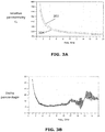
- FIG. 3A depicts the relative permittivity ⁇ r vs. frequency in GHz of the EC cell of FIG. 2A .
- ⁇ r is shown as curve 304.
- FIG. 3B shows the percentage dielectric tunability for the curves of FIG. 3A .
- FIG. 4A depicts the relative permittivity ⁇ r vs. frequency in GHz of the EC cell of FIG. 2B .
- FIG. 4B shows the percentage dielectric tunability for the curves of FIG. 4A .
- EC cell 114 achieves a dielectric tunability of no less than 78%.
- FIGS. 3A, 3B , 4A and 4B depict example embodiments of a DC bias voltage of 4V, any voltage up to approximately 10 V may be used.
- the DC bias voltage depends on a number of factors, including thickness of the layers in the EC cell.
- Each of the layers in an EC cell exhibits a capacitance, with the total equivalent capacitance of the EC cell related to the sum of the capacitances of the constituent layers.
- the capacitance of each layer is proportional to the dielectric permittivity. By modulating the dielectric permittivity, it is possible to change the operational characteristics of the EC cell.
- the EC cells described above have many applications in both the MM-wave and optical domains, for example, displays with a tailor-made optical response and beam-forming function as well as tunable optical and microwave devices, such as phase shifters, switches, attenuators and antennas.
- An EC cell as described above may be fabricated using a variety of semiconductor device manufacturing processes including, for example, chemical vapor deposition (CVD) and reactive-ion etching (RIE).
- CVD chemical vapor deposition
- RIE reactive-ion etching
Abstract
Description
- Various example embodiments relate generally to electrochromic (EC) cells and more particularly to improved dielectric tunability for an EC cell.
- Electrochromic materials are materials that allow their optical and/or electrical properties to be controlled by applying a voltage. An example of a use of electrochromic materials is in electrochromic devices such as windows and mirrors, where the application of a voltage to one or more layers of EC material sandwiched between electrodes changes the transmission or reflection properties, and/or the electrical properties, of the device.
- Example embodiments encompass an electrochromic (EC) cell having improved dielectric tunability and lower dielectric losses. In an embodiment, the EC cell is a multi-layer electrochromic structure having a top electrode layer; a bottom electrode layer; a least one electrochromic layer between the top and bottom layers; a first electrolyte layer between the at least one electrochromic layer and the top layer; and a second electrolyte layer between the at least one electrochromic layer and the bottom layer.
- In another embodiment, a mm-wave device with tunable capacitance includes a top electrode layer; a bottom electrode layer; a least one electrochromic layer between the top and bottom layers; a first electrolyte layer between the at least one electrochromic layer and the top layer; a second electrolyte layer between the at least one electrochromic layer and the bottom layer; and a voltage source for applying a voltage between the top electrode layer and the bottom electrode layer.
- In either of the above embodiments, the at least one electrochromic layer includes an electrochromic film layer and an ion storage film layer wherein the electrochromic film layer is between the second electrolyte layer and the ion storage film layer.
- In any of the above embodiments, the electrochromic film layer and the ion storage film layer further comprise transition metal oxides and the electrochromic film layer is selected from the group consisting of tungsten tri-oxide (WO3), titanium oxide (TiO2), molybdenum trioxide (MoO3), tantalum oxide (Ta2O5) and niobium pentoxide (Nb2O5) while the ion storage film layer is selected from the group consisting of nickel oxide (NiO), chromium oxide (Cr2O3), manganese oxide (MnO2), iron oxide (FeO2), cobalt oxide (CoO2), rhodium oxide (RhO2) and iridium oxide (IrO2).
- In an embodiment, the electrochromic file layer is tungsten tri-oxide (WO3) and the ion storage film layer comprises nickel oxide (NiO).
- In any of the above embodiments, the electrolyte layers are an electrolyte displaying different ion and electron conductivities, for example, lithium niobate (LiNbO3).
- In any of the above embodiments, the electrochromic film layer, the ion storage film layer and the first and second electrolyte layers have thicknesses between 50 nm and 1 micron.
- Some example embodiments will now be described with reference to the accompanying drawings in which:
-
FIGS. 1A and1B show perspective views of electrochromic (EC) cells. -
FIGS. 2A and 2B depict cross-sectional diagrams of EC cell layers of the EC cells ofFIGS. 1A and1B , respectively. -
FIGS. 3A and 3B depict dielectric permittivity at 0V and 4V, respectively, for the EC cell ofFIG. 2A . -
FIGS. 4A and 4B depict dielectric permittivity at 0V and 4V, respectively, for the EC cell ofFIG. 2B . - Electrochromic (EC) materials are materials that allow their optical and/or electrical properties to be controlled by applying a voltage. EC materials are often used as one of the layers in a multi-layer structure known as an electrochromic (EC) cell. Various characteristics of an EC cell may be engineered to tailor the EC cell for a variety of applications without changing its material composition.
- An embodiment of an
EC cell 100 is shown inFIG. 1A . Glass (not shown) may be used as a substrate on which is formed several layers. These layers include two conductinglayers EC layer 106, for example, a transition metal oxide, adjacent to conductinglayer 102 and an ion-conducting orelectrolyte layer 108 betweenEC layer 106 and either the other conductinglayer 104 or asecond EC layer 110. In an embodiment,layer 108 is lithium niobate (LiNbO3), although any electrolyte displaying different ion and electron conductivities, typically

- In an embodiment,
layers Layer 106 is a chromic film, for example, tungsten tri-oxide (WO3), however, a variety of other transition metal oxides may be used, such as titanium oxide (TiO2), molybdenum trioxide (MoO3), tantalum oxide (Ta2O5) or niobium pentoxide (Nb2O5).Layer 110 is another chromic film, also understood as an ion storage film, chosen to have complementary electrochromic characteristics tochromic film layer 106.Layer 110 may be, for example, nickel oxide (NiO), although a variety of other transition metal oxides, such as chromium oxide (Cr2O3), manganese oxide (MnO2), iron oxide (FeO2), cobalt oxide (CoO2), rhodium oxide (RhO2) or iridium oxide (IrO2). -
EC cell 100 is actuated by applying a voltage toconductive layers voltage source 112. In a non-actuated state,EC layers Electrolyte layer 108 is non-conductive in both actuated and non-actuated states. Upon application of a DC bias voltage between conductinglayers electrolyte layer 108 are expelled and subsequently injected into the one ormore EC layers -
FIG. 1B illustrates another embodiment of an electrochromic (EC) cell at 114. Top andbottom layers Layer 120 is a chromic film, for example, tungsten tri-oxide (WO3), however, a variety of other transition metal oxides may be used, such as titanium oxide (TiO2), molybdenum trioxide (MoO3), tantalum oxide (Ta2O5) or niobium pentoxide (Nb2O5).Layer 122 is another chromic film, also understood as an ion storage film, chosen to have complementary electrochromic characteristics tochromic film layer 120.Layer 122 may be, for example, nickel oxide (NiO), although a variety of other transition metal oxides, such as chromium oxide (Cr2O3), manganese oxide (MnO2), iron oxide (FeO2), cobalt oxide (CoO2), rhodium oxide (RhO2) or iridium oxide (IrO2). In an alternative embodiment ofEC cell 114,layer 122 is not present. -
Layers layers 

Layers chromic layers bottom layer 116 andtop layer 118. This voltage is provided by, for example,voltage source 128.Layers - Depending on the application,
EC cell 114 ofFIG. 1B may also include one or more substrates, not shown for conciseness. These substrates may be glass, for example, but any structurally stable substrates may be used. - In order to explain the operation of
EC cells FIGS. 1A and1B , the diagrams ofFIGS. 2A and 2B are provided.FIG. 2A depicts a cross-sectional view of internal layers ofEC cell 100 as shown inFIG. 1A . Although specific materials are shown, one of ordinary skill in the art would understand that the following discussion applies to any of the alternative materials for these layers as described above. InFIG. 2A , an ion-conducting orelectrolyte layer 204 of LiNbO3 is sandwiched between anEC film layer 202 of WO3 and an ionstorage film layer 206 of NiO. The total height of the layers without DC bias voltage applied to external electrodes (not shown) attached at the top and bottom of thelayers layer 204 intercalate intolayers -
FIG. 2B depicts a cross-sectional view of internal layers ofEC cell 114 ofFIG. 1B . In this EC cell,EC film layer 210 of WO3 and an ionstorage film layer 212 of NiO have been moved away from the external electrodes (not shown) into the interior of the EC cell. An ion-conducting or electrolyte layer is split into twolayers layers - As described above, when a voltage is applied across
EC cells FIGS. 1A and1B for a variety of applications. -
FIG. 3A depicts the relative permittivity εr vs. frequency in GHz of the EC cell ofFIG. 2A . In an actuated state (DC bias voltage = 4V), εr is shown ascurve 302 and in a non-actuated state (DC bias voltage = 0V) εr is shown ascurve 304.FIG. 3B shows the percentage dielectric tunability for the curves ofFIG. 3A . In an example embodiment of this EC cell, the thicknesses of the individual layers are hLiNbO3 = 700 nm, the hWO3 = 130 nm and hNiO = 140 nm. Although specific thicknesses are shown for the purposes of illustration, all three layers of the EC cell ofFIG. 2A may vary between approximately 50 nm and 1 micron. As is evident fromFIG. 3B , the EC cell ofFIG. 2A achieves a dielectric tunability pf approximately 11%. -
FIG. 4A depicts the relative permittivity εr vs. frequency in GHz of the EC cell ofFIG. 2B .FIG. 4A shows permittivity when the EC cell is in an actuated state (DC bias voltage = 4V) ascurve 402 and a non-actuated state (DC bias voltage = 0V) ascurve 404.FIG. 4B shows the percentage dielectric tunability for the curves ofFIG. 4A . In an example embodiment of this EC cell, the thicknesses of the individual layers are hLiNbO3 = 150 nm and hWO3 = 140 nm. Although specific thicknesses are shown for the purposes of illustration, all four layers of the EC cell ofFIG. 2B may vary between approximately 50 nm and 1 micron. As is evident fromFIGS. 4A and 4B ,EC cell 114 achieves a dielectric tunability of no less than 78%. - With regard to
FIGS. 3A, 3B ,4A and 4B , although these figures depict example embodiments of a DC bias voltage of 4V, any voltage up to approximately 10 V may be used. The DC bias voltage depends on a number of factors, including thickness of the layers in the EC cell. - Each of the layers in an EC cell exhibits a capacitance, with the total equivalent capacitance of the EC cell related to the sum of the capacitances of the constituent layers. The capacitance of each layer is proportional to the dielectric permittivity. By modulating the dielectric permittivity, it is possible to change the operational characteristics of the EC cell. Thus, the EC cells described above have many applications in both the MM-wave and optical domains, for example, displays with a tailor-made optical response and beam-forming function as well as tunable optical and microwave devices, such as phase shifters, switches, attenuators and antennas.
- An EC cell as described above may be fabricated using a variety of semiconductor device manufacturing processes including, for example, chemical vapor deposition (CVD) and reactive-ion etching (RIE).
- If used and unless otherwise stated, the terms "upper," "lower," "front," "back," "over," "under," and similar such terms are not to be construed as limiting embodiments to a particular orientation. Instead, these terms are used only on a relative basis.
Claims (20)
- A multi-layer electrochromic structure (100) comprising:a top electrode layer (104);a bottom electrode layer (102);a least one electrochromic layer (108) between the top and bottom layers;a first electrolyte layer (110) between the at least one electrochromic layer and the top layer; anda second electrolyte layer (106) between the at least one electrochromic layer and the bottom layer.
- The multi-layer electrochromic structure of claim 1 wherein the at least one electrochromic layer further comprises an electrochromic film layer (120) and an ion storage film layer (122).
- The multi-layer electrochromic structure of claim 2 wherein the electrochromic film layer is between the second electrolyte layer and the ion storage film layer.
- The multi-layer electrochromic structure of claim 2 wherein the electrochromic film layer and the ion storage film layer further comprise transition metal oxides.
- The multi-layer electrochromic structure of claim 4 wherein the electrochromic film layer comprises a transition metal oxide selected from the group consisting of tungsten trioxide (WO3), titanium oxide (TiO2), molybdenum trioxide (MoO3), tantalum oxide (Ta2O5) and niobium pentoxide (Nb2O5).
- The multi-layer electrochromic structure of claim 4 wherein the electrochromic film layer comprises tungsten oxide (WO3).
- The multi-layer electrochromic structure of claim 4 wherein the ion storage film
layer comprises a transition metal oxide selected from the group consisting of nickel oxide (NiO), chromium oxide (Cr2O3), manganese oxide (MnO2), iron oxide (FeO2), cobalt oxide (CoO2), rhodium oxide (RhO2) and iridium oxide (IrO2). - The multi-layer electrochromic structure of claim 4 wherein the ion storage film layer comprises nickel oxide (NiO).
- The multi-layer electrochromic structure of claim 2 wherein the electrochromic film layer and the ion storage film layer have thicknesses between 50 nm and 1 micron.
- The multi-layer electrochromic structure of claim 1 wherein the electrolyte layers comprise an electrolyte displaying different ion and electron conductivities.
- The multi-layer electrochromic structure of claim 10 wherein the first and second electrolyte layers comprise lithium niobate (LiNbO3).
- The multi-layer electrochromic structure of claim 1 wherein the first and second electrolyte layers have thicknesses between 50 nm and 1 micron.
- A mm-wave device with tunable capacitance, comprising:a top electrode layer;a bottom electrode layer;a least one electrochromic layer between the top and bottom layers;a first electrolyte layer between the at least one electrochromic layer and the top layer;a second electrolyte layer between the at least one electrochromic layer and the bottom layer; anda voltage source for applying a voltage between the top electrode layer and the bottom electrode layer.
- The mm-wave device of claim 13 wherein the at least one electrochromic layer further comprises an electrochromic film layer and an ion storage film layer.
- The mm-wave device of claim 14 wherein the electrochromic film layer is between the second electrolyte layer and the ion storage film layer.
- The mm-wave device of claim 14 wherein the electrochromic film layer, the ion storage film layer, and the first and second electrolyte layers have thicknesses between 50 nm and 1 micron.
- The mm-wave device of claim 16 wherein the electrochromic film layer comprises a transition metal oxide selected from the group consisting of tungsten tri-oxide (WO3), titanium oxide (TiO2), molybdenum trioxide (MoO3), tantalum oxide (Ta2O5) and niobium pentoxide (Nb2O5).
- The mm-wave device of claim 16 wherein the ion storage film layer comprises a transition metal oxide selected from the group consisting of nickel oxide (NiO), chromium oxide
(Cr2O3), manganese oxide (MnO2), iron oxide (FeO2), cobalt oxide (CoO2), rhodium oxide (RhO2) and iridium oxide (IrO2). - The mm-wave device of claim 13 wherein the electrolyte layers comprise an electrolyte displaying different ion and electron conductivities.
- The mm-wave device of claim 19 wherein the first and second electrolyte layers are lithium niobate (LiNbO3).
Applications Claiming Priority (1)
| Application Number | Priority Date | Filing Date | Title |
|---|---|---|---|
| US15/978,370 US10732476B2 (en) | 2018-05-14 | 2018-05-14 | Electrochromic cell |
Publications (1)
| Publication Number | Publication Date |
|---|---|
| EP3570100A1 true EP3570100A1 (en) | 2019-11-20 |
Family
ID=66529841
Family Applications (1)
| Application Number | Title | Priority Date | Filing Date |
|---|---|---|---|
| EP19174036.4A Pending EP3570100A1 (en) | 2018-05-14 | 2019-05-13 | Electrochromic cell |
Country Status (3)
| Country | Link |
|---|---|
| US (1) | US10732476B2 (en) |
| EP (1) | EP3570100A1 (en) |
| CN (1) | CN110488550B (en) |
Families Citing this family (8)
| Publication number | Priority date | Publication date | Assignee | Title |
|---|---|---|---|---|
| US11139544B2 (en) | 2019-09-06 | 2021-10-05 | Nokia Technologies Oy | Electrically tunable radio-frequency components and circuits |
| US11264720B2 (en) | 2019-10-28 | 2022-03-01 | Nokia Technologies Oy | Tunable radio-frequency device having electrochromic and electro-active materials |
| US11703737B2 (en) * | 2020-02-12 | 2023-07-18 | Sage Electrochromics, Inc. | Forming electrochromic stacks using at most one metallic lithium deposition station |
| EP3879623A1 (en) * | 2020-03-11 | 2021-09-15 | Nokia Technologies Oy | Apparatus comprising a waveguide for radio frequency signals |
| FI20206043A1 (en) | 2020-10-22 | 2022-04-23 | Nokia Technologies Oy | Controllable Radio Frequency Switching and/or Splitting device |
| CN112835238B (en) * | 2021-03-10 | 2022-11-22 | 维沃移动通信有限公司 | Electronic device and housing assembly |
| CN114477789B (en) * | 2022-02-11 | 2022-11-22 | 中国海洋大学 | Solvothermal preparation method of titanium-doped nickel oxide electrochromic film |
| US11444334B1 (en) | 2022-05-04 | 2022-09-13 | King Fahd University Of Petroleum And Minerals | Nickel oxide (NiO) nano-sheets based electrochromic energy storage device |
Citations (4)
| Publication number | Priority date | Publication date | Assignee | Title |
|---|---|---|---|---|
| US6277523B1 (en) * | 1996-03-27 | 2001-08-21 | Saint-Gobain Vitrage | Electrochemical device |
| WO2004017134A1 (en) * | 2002-08-15 | 2004-02-26 | Koninklijke Philips Electronics N.V. | Full-color electrochromic display with stacked in cell monochromic electrochromes |
| US20090323155A1 (en) * | 2008-06-25 | 2009-12-31 | Phillips Roger W | Multi-Cell Solid-State Electrochromic Device |
| US20100079844A1 (en) * | 2008-09-30 | 2010-04-01 | Kurman Eric W | Resonant cavity electrochromic device |
Family Cites Families (11)
| Publication number | Priority date | Publication date | Assignee | Title |
|---|---|---|---|---|
| JP2512568B2 (en) * | 1989-10-19 | 1996-07-03 | 積水化学工業株式会社 | Method for manufacturing electrochromic display device |
| JPH0473621A (en) * | 1990-07-12 | 1992-03-09 | Sekisui Chem Co Ltd | Electrochromic display device |
| US6420071B1 (en) | 2000-03-21 | 2002-07-16 | Midwest Research Institute | Method for improving the durability of ion insertion materials |
| GB0015664D0 (en) | 2000-06-28 | 2000-08-16 | Secr Defence | Electrochromic devices |
| JP4589915B2 (en) | 2003-01-31 | 2010-12-01 | エヌテラ リミテッド | Electrochromic display device |
| US20070143774A1 (en) * | 2005-07-29 | 2007-06-21 | Anoop Agrawal | Structures and processes for controlling access to optical media |
| US7609433B2 (en) | 2007-06-07 | 2009-10-27 | Soladigm, Inc. | Electrochromic device and method of making the same |
| CN102338960A (en) * | 2010-07-26 | 2012-02-01 | 介面光电股份有限公司 | 2D/3D(2 dimensional/3 dimensional) image switching display device |
| US9377663B2 (en) | 2013-01-21 | 2016-06-28 | Kinestral Technologies, Inc. | Electrochromic lithium nickel group 4 mixed metal oxides |
| KR102137519B1 (en) | 2014-01-15 | 2020-07-24 | 삼성전자주식회사 | Electrochromic device |
| CN105644449B (en) * | 2016-01-11 | 2018-01-30 | 深圳市华星光电技术有限公司 | Antiglaring rear mirror |
-
2018
- 2018-05-14 US US15/978,370 patent/US10732476B2/en active Active
-
2019
- 2019-05-13 EP EP19174036.4A patent/EP3570100A1/en active Pending
- 2019-05-14 CN CN201910400062.4A patent/CN110488550B/en active Active
Patent Citations (4)
| Publication number | Priority date | Publication date | Assignee | Title |
|---|---|---|---|---|
| US6277523B1 (en) * | 1996-03-27 | 2001-08-21 | Saint-Gobain Vitrage | Electrochemical device |
| WO2004017134A1 (en) * | 2002-08-15 | 2004-02-26 | Koninklijke Philips Electronics N.V. | Full-color electrochromic display with stacked in cell monochromic electrochromes |
| US20090323155A1 (en) * | 2008-06-25 | 2009-12-31 | Phillips Roger W | Multi-Cell Solid-State Electrochromic Device |
| US20100079844A1 (en) * | 2008-09-30 | 2010-04-01 | Kurman Eric W | Resonant cavity electrochromic device |
Also Published As
| Publication number | Publication date |
|---|---|
| CN110488550B (en) | 2022-09-20 |
| US20190346730A1 (en) | 2019-11-14 |
| US10732476B2 (en) | 2020-08-04 |
| CN110488550A (en) | 2019-11-22 |
Similar Documents
| Publication | Publication Date | Title |
|---|---|---|
| US10732476B2 (en) | Electrochromic cell | |
| EP3561890B1 (en) | Electrochromic switch | |
| US20180301783A1 (en) | Electrically controllable radio-frequency circuit element having an electrochromic material | |
| KR102010753B1 (en) | Electrochromic device | |
| CN111200182B (en) | Electrochromic reflective array antenna | |
| US10871696B2 (en) | Electrochromic device | |
| US20190011794A1 (en) | Electrochromic device | |
| US20150325897A1 (en) | Electrically controllable radio-frequency circuit element having an electrochromic material | |
| EP3319165B1 (en) | A radio frequency reflection type phase shifter, and method of phase shifting | |
| US11309729B2 (en) | Apparatus comprising a first and second layer of conductive material and methods of manufacturing and operating such apparatus | |
| CN112448105A (en) | Phase shifter and antenna | |
| US11139544B2 (en) | Electrically tunable radio-frequency components and circuits | |
| EP3470914A1 (en) | Electrochromic device | |
| US11594795B2 (en) | Switchable element | |
| KR102079142B1 (en) | An Electrochromic Device | |
| KR102108562B1 (en) | An Electrochromic Device | |
| KR102056599B1 (en) | An Electrochromic Device | |
| JP2008233513A (en) | Optical modulator | |
| KR960001813A (en) | Display device and manufacturing method | |
| CN113632368A (en) | Apparatus for operating electroactive device and method of using same | |
| CN116699917B (en) | Electrochromic device and method | |
| EP3605218B1 (en) | Electrochromic device | |
| KR102071901B1 (en) | Electrochromic device |
Legal Events
| Date | Code | Title | Description |
|---|---|---|---|
| PUAI | Public reference made under article 153(3) epc to a published international application that has entered the european phase |
Free format text: ORIGINAL CODE: 0009012 |
|
| STAA | Information on the status of an ep patent application or granted ep patent |
Free format text: STATUS: THE APPLICATION HAS BEEN PUBLISHED |
|
| AK | Designated contracting states |
Kind code of ref document: A1 Designated state(s): AL AT BE BG CH CY CZ DE DK EE ES FI FR GB GR HR HU IE IS IT LI LT LU LV MC MK MT NL NO PL PT RO RS SE SI SK SM TR |
|
| AX | Request for extension of the european patent |
Extension state: BA ME |
|
| STAA | Information on the status of an ep patent application or granted ep patent |
Free format text: STATUS: REQUEST FOR EXAMINATION WAS MADE |
|
| 17P | Request for examination filed |
Effective date: 20200520 |
|
| RBV | Designated contracting states (corrected) |
Designated state(s): AL AT BE BG CH CY CZ DE DK EE ES FI FR GB GR HR HU IE IS IT LI LT LU LV MC MK MT NL NO PL PT RO RS SE SI SK SM TR |
|
| STAA | Information on the status of an ep patent application or granted ep patent |
Free format text: STATUS: EXAMINATION IS IN PROGRESS |
|
| 17Q | First examination report despatched |
Effective date: 20210709 |