EP3570080A1 - Laminate, method for producing laminate, and room mirror for vehicles - Google Patents
Laminate, method for producing laminate, and room mirror for vehicles Download PDFInfo
- Publication number
- EP3570080A1 EP3570080A1 EP17891362.0A EP17891362A EP3570080A1 EP 3570080 A1 EP3570080 A1 EP 3570080A1 EP 17891362 A EP17891362 A EP 17891362A EP 3570080 A1 EP3570080 A1 EP 3570080A1
- Authority
- EP
- European Patent Office
- Prior art keywords
- multilayer film
- polarized light
- polarization axis
- layers
- laminated body
- Prior art date
- Legal status (The legal status is an assumption and is not a legal conclusion. Google has not performed a legal analysis and makes no representation as to the accuracy of the status listed.)
- Granted
Links
- 238000004519 manufacturing process Methods 0.000 title claims abstract description 13
- 239000010410 layer Substances 0.000 claims abstract description 62
- 230000010287 polarization Effects 0.000 claims abstract description 61
- 230000009477 glass transition Effects 0.000 claims abstract description 25
- 239000000758 substrate Substances 0.000 claims abstract description 24
- 239000012790 adhesive layer Substances 0.000 claims abstract description 20
- 229920000642 polymer Polymers 0.000 claims abstract description 18
- KYTZHLUVELPASH-UHFFFAOYSA-N naphthalene-1,2-dicarboxylic acid Chemical compound C1=CC=CC2=C(C(O)=O)C(C(=O)O)=CC=C21 KYTZHLUVELPASH-UHFFFAOYSA-N 0.000 claims abstract description 16
- 229920000728 polyester Polymers 0.000 claims abstract description 15
- 238000000034 method Methods 0.000 claims description 13
- 230000015572 biosynthetic process Effects 0.000 abstract description 9
- NIXOWILDQLNWCW-UHFFFAOYSA-M Acrylate Chemical compound [O-]C(=O)C=C NIXOWILDQLNWCW-UHFFFAOYSA-M 0.000 description 30
- 239000011112 polyethylene naphthalate Substances 0.000 description 14
- 229920003207 poly(ethylene-2,6-naphthalate) Polymers 0.000 description 13
- 238000011156 evaluation Methods 0.000 description 10
- -1 polybutylene Polymers 0.000 description 10
- 229920001634 Copolyester Polymers 0.000 description 9
- VYPSYNLAJGMNEJ-UHFFFAOYSA-N Silicium dioxide Chemical compound O=[Si]=O VYPSYNLAJGMNEJ-UHFFFAOYSA-N 0.000 description 9
- 239000000853 adhesive Substances 0.000 description 9
- 230000001070 adhesive effect Effects 0.000 description 9
- 230000000052 comparative effect Effects 0.000 description 8
- 229920000139 polyethylene terephthalate Polymers 0.000 description 8
- 239000005020 polyethylene terephthalate Substances 0.000 description 8
- LYCAIKOWRPUZTN-UHFFFAOYSA-N Ethylene glycol Chemical compound OCCO LYCAIKOWRPUZTN-UHFFFAOYSA-N 0.000 description 7
- 239000000463 material Substances 0.000 description 7
- KKEYFWRCBNTPAC-UHFFFAOYSA-N Terephthalic acid Chemical compound OC(=O)C1=CC=C(C(O)=O)C=C1 KKEYFWRCBNTPAC-UHFFFAOYSA-N 0.000 description 6
- 239000004973 liquid crystal related substance Substances 0.000 description 6
- NIXOWILDQLNWCW-UHFFFAOYSA-N acrylic acid group Chemical group C(C=C)(=O)O NIXOWILDQLNWCW-UHFFFAOYSA-N 0.000 description 5
- 125000000217 alkyl group Chemical group 0.000 description 4
- WERYXYBDKMZEQL-UHFFFAOYSA-N butane-1,4-diol Chemical compound OCCCCO WERYXYBDKMZEQL-UHFFFAOYSA-N 0.000 description 4
- 230000003287 optical effect Effects 0.000 description 4
- 230000000930 thermomechanical effect Effects 0.000 description 4
- MTHSVFCYNBDYFN-UHFFFAOYSA-N diethylene glycol Chemical compound OCCOCCO MTHSVFCYNBDYFN-UHFFFAOYSA-N 0.000 description 3
- ORLQHILJRHBSAY-UHFFFAOYSA-N [1-(hydroxymethyl)cyclohexyl]methanol Chemical compound OCC1(CO)CCCCC1 ORLQHILJRHBSAY-UHFFFAOYSA-N 0.000 description 2
- 150000001252 acrylic acid derivatives Chemical class 0.000 description 2
- 239000003522 acrylic cement Substances 0.000 description 2
- WNLRTRBMVRJNCN-UHFFFAOYSA-N adipic acid Chemical compound OC(=O)CCCCC(O)=O WNLRTRBMVRJNCN-UHFFFAOYSA-N 0.000 description 2
- IISBACLAFKSPIT-UHFFFAOYSA-N bisphenol A Chemical compound C=1C=C(O)C=CC=1C(C)(C)C1=CC=C(O)C=C1 IISBACLAFKSPIT-UHFFFAOYSA-N 0.000 description 2
- 229920001577 copolymer Polymers 0.000 description 2
- QQVIHTHCMHWDBS-UHFFFAOYSA-N isophthalic acid Chemical compound OC(=O)C1=CC=CC(C(O)=O)=C1 QQVIHTHCMHWDBS-UHFFFAOYSA-N 0.000 description 2
- 238000005259 measurement Methods 0.000 description 2
- BDJRBEYXGGNYIS-UHFFFAOYSA-N nonanedioic acid Chemical compound OC(=O)CCCCCCCC(O)=O BDJRBEYXGGNYIS-UHFFFAOYSA-N 0.000 description 2
- 229920001707 polybutylene terephthalate Polymers 0.000 description 2
- ULWHHBHJGPPBCO-UHFFFAOYSA-N propane-1,1-diol Chemical compound CCC(O)O ULWHHBHJGPPBCO-UHFFFAOYSA-N 0.000 description 2
- 229920006395 saturated elastomer Polymers 0.000 description 2
- CXMXRPHRNRROMY-UHFFFAOYSA-N sebacic acid Chemical compound OC(=O)CCCCCCCCC(O)=O CXMXRPHRNRROMY-UHFFFAOYSA-N 0.000 description 2
- 238000001179 sorption measurement Methods 0.000 description 2
- KKEYFWRCBNTPAC-UHFFFAOYSA-L terephthalate(2-) Chemical compound [O-]C(=O)C1=CC=C(C([O-])=O)C=C1 KKEYFWRCBNTPAC-UHFFFAOYSA-L 0.000 description 2
- 125000003837 (C1-C20) alkyl group Chemical group 0.000 description 1
- VZSRBBMJRBPUNF-UHFFFAOYSA-N 2-(2,3-dihydro-1H-inden-2-ylamino)-N-[3-oxo-3-(2,4,6,7-tetrahydrotriazolo[4,5-c]pyridin-5-yl)propyl]pyrimidine-5-carboxamide Chemical compound C1C(CC2=CC=CC=C12)NC1=NC=C(C=N1)C(=O)NCCC(N1CC2=C(CC1)NN=N2)=O VZSRBBMJRBPUNF-UHFFFAOYSA-N 0.000 description 1
- IAXFZZHBFXRZMT-UHFFFAOYSA-N 2-[3-(2-hydroxyethoxy)phenoxy]ethanol Chemical compound OCCOC1=CC=CC(OCCO)=C1 IAXFZZHBFXRZMT-UHFFFAOYSA-N 0.000 description 1
- 239000004925 Acrylic resin Substances 0.000 description 1
- 229920000178 Acrylic resin Polymers 0.000 description 1
- SNRUBQQJIBEYMU-UHFFFAOYSA-N Dodecane Natural products CCCCCCCCCCCC SNRUBQQJIBEYMU-UHFFFAOYSA-N 0.000 description 1
- JOYRKODLDBILNP-UHFFFAOYSA-N Ethyl urethane Chemical compound CCOC(N)=O JOYRKODLDBILNP-UHFFFAOYSA-N 0.000 description 1
- 239000002202 Polyethylene glycol Substances 0.000 description 1
- 238000010521 absorption reaction Methods 0.000 description 1
- 239000002253 acid Substances 0.000 description 1
- 235000011037 adipic acid Nutrition 0.000 description 1
- 239000001361 adipic acid Substances 0.000 description 1
- 125000001204 arachidyl group Chemical group [H]C([*])([H])C([H])([H])C([H])([H])C([H])([H])C([H])([H])C([H])([H])C([H])([H])C([H])([H])C([H])([H])C([H])([H])C([H])([H])C([H])([H])C([H])([H])C([H])([H])C([H])([H])C([H])([H])C([H])([H])C([H])([H])C([H])([H])C([H])([H])[H] 0.000 description 1
- 229920005601 base polymer Polymers 0.000 description 1
- 230000005540 biological transmission Effects 0.000 description 1
- CDQSJQSWAWPGKG-UHFFFAOYSA-N butane-1,1-diol Chemical compound CCCC(O)O CDQSJQSWAWPGKG-UHFFFAOYSA-N 0.000 description 1
- 125000000484 butyl group Chemical group [H]C([*])([H])C([H])([H])C([H])([H])C([H])([H])[H] 0.000 description 1
- 125000004432 carbon atom Chemical group C* 0.000 description 1
- 210000004027 cell Anatomy 0.000 description 1
- 238000000576 coating method Methods 0.000 description 1
- 210000002858 crystal cell Anatomy 0.000 description 1
- QYQADNCHXSEGJT-UHFFFAOYSA-N cyclohexane-1,1-dicarboxylate;hydron Chemical compound OC(=O)C1(C(O)=O)CCCCC1 QYQADNCHXSEGJT-UHFFFAOYSA-N 0.000 description 1
- 125000002704 decyl group Chemical group [H]C([H])([H])C([H])([H])C([H])([H])C([H])([H])C([H])([H])C([H])([H])C([H])([H])C([H])([H])C([H])([H])C([H])([H])* 0.000 description 1
- 150000002009 diols Chemical class 0.000 description 1
- 125000003438 dodecyl group Chemical group [H]C([H])([H])C([H])([H])C([H])([H])C([H])([H])C([H])([H])C([H])([H])C([H])([H])C([H])([H])C([H])([H])C([H])([H])C([H])([H])C([H])([H])* 0.000 description 1
- 238000001035 drying Methods 0.000 description 1
- 230000009977 dual effect Effects 0.000 description 1
- 125000001495 ethyl group Chemical group [H]C([H])([H])C([H])([H])* 0.000 description 1
- 238000001125 extrusion Methods 0.000 description 1
- 125000003827 glycol group Chemical group 0.000 description 1
- 238000010438 heat treatment Methods 0.000 description 1
- 125000003187 heptyl group Chemical group [H]C([*])([H])C([H])([H])C([H])([H])C([H])([H])C([H])([H])C([H])([H])C([H])([H])[H] 0.000 description 1
- 125000004051 hexyl group Chemical group [H]C([H])([H])C([H])([H])C([H])([H])C([H])([H])C([H])([H])C([H])([H])* 0.000 description 1
- 229920001519 homopolymer Polymers 0.000 description 1
- WGCNASOHLSPBMP-UHFFFAOYSA-N hydroxyacetaldehyde Natural products OCC=O WGCNASOHLSPBMP-UHFFFAOYSA-N 0.000 description 1
- 125000000959 isobutyl group Chemical group [H]C([H])([H])C([H])(C([H])([H])[H])C([H])([H])* 0.000 description 1
- 125000001449 isopropyl group Chemical group [H]C([H])([H])C([H])(*)C([H])([H])[H] 0.000 description 1
- 125000002960 margaryl group Chemical group [H]C([*])([H])C([H])([H])C([H])([H])C([H])([H])C([H])([H])C([H])([H])C([H])([H])C([H])([H])C([H])([H])C([H])([H])C([H])([H])C([H])([H])C([H])([H])C([H])([H])C([H])([H])C([H])([H])C([H])([H])[H] 0.000 description 1
- 125000005395 methacrylic acid group Chemical group 0.000 description 1
- 125000002496 methyl group Chemical group [H]C([H])([H])* 0.000 description 1
- 239000000203 mixture Substances 0.000 description 1
- 239000000178 monomer Substances 0.000 description 1
- 125000001421 myristyl group Chemical group [H]C([*])([H])C([H])([H])C([H])([H])C([H])([H])C([H])([H])C([H])([H])C([H])([H])C([H])([H])C([H])([H])C([H])([H])C([H])([H])C([H])([H])C([H])([H])C([H])([H])[H] 0.000 description 1
- 125000005487 naphthalate group Chemical group 0.000 description 1
- RXOHFPCZGPKIRD-UHFFFAOYSA-N naphthalene-2,6-dicarboxylic acid Chemical compound C1=C(C(O)=O)C=CC2=CC(C(=O)O)=CC=C21 RXOHFPCZGPKIRD-UHFFFAOYSA-N 0.000 description 1
- WPUMVKJOWWJPRK-UHFFFAOYSA-N naphthalene-2,7-dicarboxylic acid Chemical compound C1=CC(C(O)=O)=CC2=CC(C(=O)O)=CC=C21 WPUMVKJOWWJPRK-UHFFFAOYSA-N 0.000 description 1
- SLCVBVWXLSEKPL-UHFFFAOYSA-N neopentyl glycol Chemical compound OCC(C)(C)CO SLCVBVWXLSEKPL-UHFFFAOYSA-N 0.000 description 1
- 125000001196 nonadecyl group Chemical group [H]C([*])([H])C([H])([H])C([H])([H])C([H])([H])C([H])([H])C([H])([H])C([H])([H])C([H])([H])C([H])([H])C([H])([H])C([H])([H])C([H])([H])C([H])([H])C([H])([H])C([H])([H])C([H])([H])C([H])([H])C([H])([H])C([H])([H])[H] 0.000 description 1
- 125000001400 nonyl group Chemical group [H]C([*])([H])C([H])([H])C([H])([H])C([H])([H])C([H])([H])C([H])([H])C([H])([H])C([H])([H])C([H])([H])[H] 0.000 description 1
- 125000002347 octyl group Chemical group [H]C([*])([H])C([H])([H])C([H])([H])C([H])([H])C([H])([H])C([H])([H])C([H])([H])C([H])([H])[H] 0.000 description 1
- 125000000913 palmityl group Chemical group [H]C([*])([H])C([H])([H])C([H])([H])C([H])([H])C([H])([H])C([H])([H])C([H])([H])C([H])([H])C([H])([H])C([H])([H])C([H])([H])C([H])([H])C([H])([H])C([H])([H])C([H])([H])C([H])([H])[H] 0.000 description 1
- 125000002958 pentadecyl group Chemical group [H]C([*])([H])C([H])([H])C([H])([H])C([H])([H])C([H])([H])C([H])([H])C([H])([H])C([H])([H])C([H])([H])C([H])([H])C([H])([H])C([H])([H])C([H])([H])C([H])([H])C([H])([H])[H] 0.000 description 1
- 125000001147 pentyl group Chemical group C(CCCC)* 0.000 description 1
- 229920003229 poly(methyl methacrylate) Polymers 0.000 description 1
- 229920000058 polyacrylate Polymers 0.000 description 1
- 229920001748 polybutylene Polymers 0.000 description 1
- 229920000515 polycarbonate Polymers 0.000 description 1
- 239000004417 polycarbonate Substances 0.000 description 1
- 229920005668 polycarbonate resin Polymers 0.000 description 1
- 239000004431 polycarbonate resin Substances 0.000 description 1
- 229920001223 polyethylene glycol Polymers 0.000 description 1
- 229920005644 polyethylene terephthalate glycol copolymer Polymers 0.000 description 1
- 239000004926 polymethyl methacrylate Substances 0.000 description 1
- 125000001436 propyl group Chemical group [H]C([*])([H])C([H])([H])C([H])([H])[H] 0.000 description 1
- 230000001681 protective effect Effects 0.000 description 1
- 239000000376 reactant Substances 0.000 description 1
- 239000011347 resin Substances 0.000 description 1
- 229920005989 resin Polymers 0.000 description 1
- 125000002914 sec-butyl group Chemical group [H]C([H])([H])C([H])([H])C([H])(*)C([H])([H])[H] 0.000 description 1
- 239000013464 silicone adhesive Substances 0.000 description 1
- 125000004079 stearyl group Chemical group [H]C([*])([H])C([H])([H])C([H])([H])C([H])([H])C([H])([H])C([H])([H])C([H])([H])C([H])([H])C([H])([H])C([H])([H])C([H])([H])C([H])([H])C([H])([H])C([H])([H])C([H])([H])C([H])([H])C([H])([H])C([H])([H])[H] 0.000 description 1
- 239000000126 substance Substances 0.000 description 1
- 125000000999 tert-butyl group Chemical group [H]C([H])([H])C(*)(C([H])([H])[H])C([H])([H])[H] 0.000 description 1
- 125000002889 tridecyl group Chemical group [H]C([*])([H])C([H])([H])C([H])([H])C([H])([H])C([H])([H])C([H])([H])C([H])([H])C([H])([H])C([H])([H])C([H])([H])C([H])([H])C([H])([H])C([H])([H])[H] 0.000 description 1
- 125000002948 undecyl group Chemical group [H]C([*])([H])C([H])([H])C([H])([H])C([H])([H])C([H])([H])C([H])([H])C([H])([H])C([H])([H])C([H])([H])C([H])([H])C([H])([H])[H] 0.000 description 1
Images


Classifications
-
- B—PERFORMING OPERATIONS; TRANSPORTING
- B32—LAYERED PRODUCTS
- B32B—LAYERED PRODUCTS, i.e. PRODUCTS BUILT-UP OF STRATA OF FLAT OR NON-FLAT, e.g. CELLULAR OR HONEYCOMB, FORM
- B32B17/00—Layered products essentially comprising sheet glass, or glass, slag, or like fibres
- B32B17/06—Layered products essentially comprising sheet glass, or glass, slag, or like fibres comprising glass as the main or only constituent of a layer, next to another layer of a specific material
- B32B17/10—Layered products essentially comprising sheet glass, or glass, slag, or like fibres comprising glass as the main or only constituent of a layer, next to another layer of a specific material of synthetic resin
-
- B—PERFORMING OPERATIONS; TRANSPORTING
- B32—LAYERED PRODUCTS
- B32B—LAYERED PRODUCTS, i.e. PRODUCTS BUILT-UP OF STRATA OF FLAT OR NON-FLAT, e.g. CELLULAR OR HONEYCOMB, FORM
- B32B27/00—Layered products comprising a layer of synthetic resin
- B32B27/36—Layered products comprising a layer of synthetic resin comprising polyesters
-
- B—PERFORMING OPERATIONS; TRANSPORTING
- B32—LAYERED PRODUCTS
- B32B—LAYERED PRODUCTS, i.e. PRODUCTS BUILT-UP OF STRATA OF FLAT OR NON-FLAT, e.g. CELLULAR OR HONEYCOMB, FORM
- B32B37/00—Methods or apparatus for laminating, e.g. by curing or by ultrasonic bonding
- B32B37/12—Methods or apparatus for laminating, e.g. by curing or by ultrasonic bonding characterised by using adhesives
-
- B—PERFORMING OPERATIONS; TRANSPORTING
- B32—LAYERED PRODUCTS
- B32B—LAYERED PRODUCTS, i.e. PRODUCTS BUILT-UP OF STRATA OF FLAT OR NON-FLAT, e.g. CELLULAR OR HONEYCOMB, FORM
- B32B38/00—Ancillary operations in connection with laminating processes
- B32B38/18—Handling of layers or the laminate
- B32B38/1875—Tensioning
-
- B—PERFORMING OPERATIONS; TRANSPORTING
- B32—LAYERED PRODUCTS
- B32B—LAYERED PRODUCTS, i.e. PRODUCTS BUILT-UP OF STRATA OF FLAT OR NON-FLAT, e.g. CELLULAR OR HONEYCOMB, FORM
- B32B7/00—Layered products characterised by the relation between layers; Layered products characterised by the relative orientation of features between layers, or by the relative values of a measurable parameter between layers, i.e. products comprising layers having different physical, chemical or physicochemical properties; Layered products characterised by the interconnection of layers
- B32B7/02—Physical, chemical or physicochemical properties
- B32B7/023—Optical properties
-
- B—PERFORMING OPERATIONS; TRANSPORTING
- B32—LAYERED PRODUCTS
- B32B—LAYERED PRODUCTS, i.e. PRODUCTS BUILT-UP OF STRATA OF FLAT OR NON-FLAT, e.g. CELLULAR OR HONEYCOMB, FORM
- B32B7/00—Layered products characterised by the relation between layers; Layered products characterised by the relative orientation of features between layers, or by the relative values of a measurable parameter between layers, i.e. products comprising layers having different physical, chemical or physicochemical properties; Layered products characterised by the interconnection of layers
- B32B7/04—Interconnection of layers
- B32B7/12—Interconnection of layers using interposed adhesives or interposed materials with bonding properties
-
- B—PERFORMING OPERATIONS; TRANSPORTING
- B60—VEHICLES IN GENERAL
- B60R—VEHICLES, VEHICLE FITTINGS, OR VEHICLE PARTS, NOT OTHERWISE PROVIDED FOR
- B60R1/00—Optical viewing arrangements; Real-time viewing arrangements for drivers or passengers using optical image capturing systems, e.g. cameras or video systems specially adapted for use in or on vehicles
- B60R1/02—Rear-view mirror arrangements
- B60R1/04—Rear-view mirror arrangements mounted inside vehicle
-
- B—PERFORMING OPERATIONS; TRANSPORTING
- B60—VEHICLES IN GENERAL
- B60R—VEHICLES, VEHICLE FITTINGS, OR VEHICLE PARTS, NOT OTHERWISE PROVIDED FOR
- B60R1/00—Optical viewing arrangements; Real-time viewing arrangements for drivers or passengers using optical image capturing systems, e.g. cameras or video systems specially adapted for use in or on vehicles
- B60R1/02—Rear-view mirror arrangements
- B60R1/08—Rear-view mirror arrangements involving special optical features, e.g. avoiding blind spots, e.g. convex mirrors; Side-by-side associations of rear-view and other mirrors
- B60R1/083—Anti-glare mirrors, e.g. "day-night" mirrors
-
- G—PHYSICS
- G02—OPTICS
- G02B—OPTICAL ELEMENTS, SYSTEMS OR APPARATUS
- G02B5/00—Optical elements other than lenses
- G02B5/08—Mirrors
- G02B5/0816—Multilayer mirrors, i.e. having two or more reflecting layers
-
- G—PHYSICS
- G02—OPTICS
- G02B—OPTICAL ELEMENTS, SYSTEMS OR APPARATUS
- G02B5/00—Optical elements other than lenses
- G02B5/30—Polarising elements
-
- G—PHYSICS
- G02—OPTICS
- G02B—OPTICAL ELEMENTS, SYSTEMS OR APPARATUS
- G02B5/00—Optical elements other than lenses
- G02B5/30—Polarising elements
- G02B5/3025—Polarisers, i.e. arrangements capable of producing a definite output polarisation state from an unpolarised input state
- G02B5/3033—Polarisers, i.e. arrangements capable of producing a definite output polarisation state from an unpolarised input state in the form of a thin sheet or foil, e.g. Polaroid
- G02B5/3041—Polarisers, i.e. arrangements capable of producing a definite output polarisation state from an unpolarised input state in the form of a thin sheet or foil, e.g. Polaroid comprising multiple thin layers, e.g. multilayer stacks
- G02B5/305—Polarisers, i.e. arrangements capable of producing a definite output polarisation state from an unpolarised input state in the form of a thin sheet or foil, e.g. Polaroid comprising multiple thin layers, e.g. multilayer stacks including organic materials, e.g. polymeric layers
-
- B—PERFORMING OPERATIONS; TRANSPORTING
- B32—LAYERED PRODUCTS
- B32B—LAYERED PRODUCTS, i.e. PRODUCTS BUILT-UP OF STRATA OF FLAT OR NON-FLAT, e.g. CELLULAR OR HONEYCOMB, FORM
- B32B2250/00—Layers arrangement
- B32B2250/05—5 or more layers
-
- B—PERFORMING OPERATIONS; TRANSPORTING
- B32—LAYERED PRODUCTS
- B32B—LAYERED PRODUCTS, i.e. PRODUCTS BUILT-UP OF STRATA OF FLAT OR NON-FLAT, e.g. CELLULAR OR HONEYCOMB, FORM
- B32B2250/00—Layers arrangement
- B32B2250/42—Alternating layers, e.g. ABAB(C), AABBAABB(C)
-
- B—PERFORMING OPERATIONS; TRANSPORTING
- B32—LAYERED PRODUCTS
- B32B—LAYERED PRODUCTS, i.e. PRODUCTS BUILT-UP OF STRATA OF FLAT OR NON-FLAT, e.g. CELLULAR OR HONEYCOMB, FORM
- B32B2307/00—Properties of the layers or laminate
- B32B2307/40—Properties of the layers or laminate having particular optical properties
- B32B2307/416—Reflective
-
- B—PERFORMING OPERATIONS; TRANSPORTING
- B32—LAYERED PRODUCTS
- B32B—LAYERED PRODUCTS, i.e. PRODUCTS BUILT-UP OF STRATA OF FLAT OR NON-FLAT, e.g. CELLULAR OR HONEYCOMB, FORM
- B32B2307/00—Properties of the layers or laminate
- B32B2307/40—Properties of the layers or laminate having particular optical properties
- B32B2307/42—Polarizing, birefringent, filtering
-
- B—PERFORMING OPERATIONS; TRANSPORTING
- B32—LAYERED PRODUCTS
- B32B—LAYERED PRODUCTS, i.e. PRODUCTS BUILT-UP OF STRATA OF FLAT OR NON-FLAT, e.g. CELLULAR OR HONEYCOMB, FORM
- B32B2315/00—Other materials containing non-metallic inorganic compounds not provided for in groups B32B2311/00 - B32B2313/04
- B32B2315/08—Glass
-
- B—PERFORMING OPERATIONS; TRANSPORTING
- B32—LAYERED PRODUCTS
- B32B—LAYERED PRODUCTS, i.e. PRODUCTS BUILT-UP OF STRATA OF FLAT OR NON-FLAT, e.g. CELLULAR OR HONEYCOMB, FORM
- B32B2371/00—Polyethers, e.g. PEEK, i.e. polyether-etherketone; PEK, i.e. polyetherketone
-
- B—PERFORMING OPERATIONS; TRANSPORTING
- B32—LAYERED PRODUCTS
- B32B—LAYERED PRODUCTS, i.e. PRODUCTS BUILT-UP OF STRATA OF FLAT OR NON-FLAT, e.g. CELLULAR OR HONEYCOMB, FORM
- B32B2551/00—Optical elements
- B32B2551/08—Mirrors
-
- B—PERFORMING OPERATIONS; TRANSPORTING
- B32—LAYERED PRODUCTS
- B32B—LAYERED PRODUCTS, i.e. PRODUCTS BUILT-UP OF STRATA OF FLAT OR NON-FLAT, e.g. CELLULAR OR HONEYCOMB, FORM
- B32B2605/00—Vehicles
Landscapes
- Physics & Mathematics (AREA)
- Engineering & Computer Science (AREA)
- General Physics & Mathematics (AREA)
- Optics & Photonics (AREA)
- Multimedia (AREA)
- Mechanical Engineering (AREA)
- Laminated Bodies (AREA)
- Polarising Elements (AREA)
Abstract
Description
- The present invention relates to a laminated body, a method for producing the laminated body, and a rearview mirror for vehicles including the laminated body.
- In recent years, multilayer films formed of polymers have been widely used for, for example, reflective polarizing plates and mirrors. Such a known multilayer film is, for example, a dual brightness enhancement film (hereafter referred to as "DBEF") disclosed in
JP1997-506837A JP-H09-506837A - However, such a multilayer film produced by performing stretching has a problem in that creases are easily formed at high temperature. To address this problem,
JP2016-62027A JP2000-321560A - However, the multilayer film may be expanded in various applications. It is proposed that, for example, the multilayer film be used as a reflective polarizing plate for large-screen liquid crystal display devices and also be used for mirror displays of rearview mirrors for vehicles. In such an operating environment, the multilayer film is frequently exposed to high temperature and humidity. This requires a multilayer film in which formation of creases is further suppressed.
- In view of the foregoing, it is an object of the present invention to provide a laminated body including a multilayer film in which formation of creases is suppressed under high temperature and humidity conditions, a method for producing the laminated body, and a rearview mirror for vehicles including the laminated body.
- As a result of thorough studies, the present inventors have found that when the thermal expansion coefficient of a multilayer film is set in a particular range in advance and the multilayer film is bonded to a substrate with an adhesive layer disposed therebetween, a laminated body in which creases are not easily formed even under high temperature and humidity conditions is provided. Thus, the present inventors have completed the present invention.
- That is, a laminated body according to an aspect of the present invention sequentially includes a substrate, an adhesive layer, and a multilayer film. The laminated body has characteristics of transmitting first polarized light and reflecting second polarized light having a polarization axis that intersects a polarization axis of the first polarized light. The multilayer film includes a plurality of first layers formed of a crystalline naphthalenedicarboxylic acid polyester and a plurality of second layers formed of a polymer other than the crystalline naphthalenedicarboxylic acid polyester, the first layers and the second layers being alternately stacked on top of each other. The first layers have a higher refractive index than the second layers on the polarization axis of the second polarized light. The multilayer film has a thermal expansion coefficient of -80 × 10-6 /K (-80 [10-6/K]) or more at a temperature 3°C higher than a glass transition point of the multilayer film in a polarization axis direction of the first polarized light.
- The "transmitting" herein means that 95% or more of light having a wavelength of 450 nm to 650 nm is transmitted. The "reflecting" herein means that 80% or more of light having a wavelength of 450 nm to 650 nm is reflected.
- The angle at which the polarization axis of the first polarized light intersects the polarization axis of the second polarized light is in the range of 87° to 93° and most preferably 90°.
- The "glass transition point of the multilayer film" is a value obtained by measuring the whole multilayer film using thermomechanical analysis (TMA). For example, trade name "TMA" (manufactured by Hitachi High-Tech Science Corporation) can be used as a thermomechanical analyzer.
- The reason for measurement "at a temperature 3°C higher than the glass transition point" is as follows.
- When the thermal expansion coefficient of the multilayer film is measured by thermomechanical analysis (TMA), a phenomenon is observed in which the thermal expansion coefficient rapidly changes near the glass transition point and then the thermal expansion coefficient is saturated. Therefore, the thermal expansion coefficient considerably varies at the glass transition point and the polymer may be denatured if the temperature is excessively high. At a temperature 3°C higher than the glass transition point, the thermal expansion coefficient is sufficiently saturated, and a stable value with less variation can be obtained. For this reason, the thermal expansion coefficient is measured at a temperature 3°C higher than the glass transition point.
- The multilayer film is preferably stretched in the polarization axis direction y of the first polarized light to 98% or more of a breaking length at 25°C in the polarization axis direction.
- The "breaking length" herein is a length at which the multilayer film is broken when the whole multilayer film is stretched in the polarization axis direction of first polarized light using a stretching machine. The stretching machine that can be used is, for example, a high-performance film stretching machine "FITZ" (manufactured by ICHIKIN Co., Ltd.).
- A method for producing a laminated body according to an aspect of the present invention is a method for producing the above laminated body according to an aspect of the present invention. The method includes setting the thermal expansion coefficient of the multilayer film to -80 [10-6/K] or more and then bonding the multilayer film and the substrate with the adhesive layer disposed therebetween.
- The multilayer film is preferably stretched in the polarization axis direction of the first polarized light to set the thermal expansion coefficient to -80 [10-6/K] or more.
- A rearview mirror for vehicles according to an aspect of the present invention is a rearview mirror for vehicles including the above laminated body according to an aspect of the present invention. A short-side direction of the rearview mirror for vehicles corresponds to the polarization axis direction of the first polarized light.
- In the laminated body, the method for producing a laminated body, and the rearview mirror for vehicles according to embodiments of the present invention, formation of creases is favorably suppressed even under high temperature and humidity conditions.
-
-
Fig. 1 is a schematic sectional view illustrating a laminated body; -
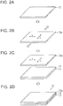
Figs. 2A to 2D schematically illustrate one embodiment of a method for producing a laminated body; -
Figs. 3A to 3C schematically illustrate another embodiment of the method for producing a laminated body; and -
Fig. 4 schematically illustrates a rearview mirror for vehicles. - Hereafter, the present invention will be described with reference to the attached drawings.
- A laminated body according to an embodiment of the present invention will be described.
- As illustrated in
Fig. 1 , a laminatedbody 10 includes anadhesive layer 12 and amultilayer film 13a on asubstrate 11 in this order. The laminatedbody 10 has characteristics of transmitting first polarized light and reflecting second polarized light having a polarization axis x that intersects a polarization axis y of the first polarized light. - As illustrated in
Fig. 1 , themultilayer film 13a includes a plurality offirst layers 131 formed of a crystalline naphthalenedicarboxylic acid polyester and a plurality ofsecond layers 132 formed of a polymer other than the crystalline naphthalenedicarboxylic acid polyester, the first layers and the second layers being alternately stacked on top of each other. Themultilayer film 13a is obtained by uniaxially or biaxially stretching a multilayer body constituted by thefirst layers 131 and thesecond layers 132. Each of thefirst layers 131 is preferably formed of a material that exhibits birefringence through stretching and each of thesecond layers 132 is preferably formed of a material that does not exhibit birefringence even if stretched (that maintains the isotropy). In this case, as a result of the uniaxial stretching or the biaxial stretching, the refractive index of thefirst layer 131 is higher than that of thesecond layer 132 on the polarization axis x of the second polarized light, and the refractive index of thefirst layer 131 is equal to that of thesecond layer 132 on the polarization axis y of the first polarized light. Consequently, the polarization axis x of the second polarized light serves as a reflection axis, and the polarization axis y of the first polarized light serves as a transmission axis. - The difference in refractive index on the polarization axis x of the second polarized light is preferably 0.2 to 0.3.
- The
multilayer film 13a has a thermal expansion coefficient of -80 [10-6/K] or more at a temperature 3°C higher than the glass transition point of the multilayer film. When the thermal expansion coefficient of the multilayer film is -80 [10-6/K] or more, a laminated body in which formation of creases is favorably suppressed even under high temperature and humidity conditions can be provided. The thermal expansion coefficient at a temperature 3°C higher than the glass transition point of the multilayer film is more preferably -70 [10-6/K] or more. The upper limit of the thermal expansion coefficient at a temperature 3°C higher than the glass transition point of the multilayer film is preferably 80 [10-6/K] or less and more preferably 70 [10-6/K] or less from the viewpoint of preventing formation of creases due to stretching of films. - Although the detail is described later, the multilayer film having such a thermal expansion coefficient is obtained by stretching a multilayer film in a polarization axis direction of the first polarized light at a particular stretch factor.
- The
first layers 131 in themultilayer film 13a are formed of a crystalline naphthalenedicarboxylic acid polyester. Examples of the crystalline naphthalenedicarboxylic acid polyester include polyethylene naphthalate (PEN), polybutylene 2,6-naphthalate (PBN), polyethylene terephthalate (PET), polycarbonate, and acrylic resin (polymethyl methacrylate). - The
first layers 131 preferably exhibit birefringence through stretching. The refractive index on the polarization axis x of second polarized light at a wavelength of 550 nm is 1.54 to 1.74, and the refractive index on the polarization axis x of the second polarized light is about 1.6 to about 1.9. - The thickness of the
first layers 131 is preferably 60 to 100 nm and more preferably 75 to 85 nm. - The "polymer other than the crystalline naphthalenedicarboxylic acid polyester" of the
second layers 132 in themultilayer film 13a refers to a "polymer that is not a crystalline naphthalenedicarboxylic acid polyester", such as a polymer different from the polymer constituting the first layers. The second layers 132 formed of a polymer other than the crystalline naphthalenedicarboxylic acid polyester are preferably formed of a material that does not exhibit birefringence even if stretched (that maintains the isotropy). When the second layers are formed of such a material, the second layers do not have optical anisotropy and thus have a birefringence index of zero. Thesecond layers 132 may be formed of, for example, any polymer that maintains isotropy when stretched. Typical examples of the material that is a polymer other than the crystalline naphthalenedicarboxylic acid polyester and that does not exhibit birefringence even if stretched include copolyesters of naphthalenedicarboxylic acid and terephthalic acid (naphthalenedicarboxylic acid copolyester (coPEN)). The molar ratio of naphthalate and terephthalate is preferably 20:80 to 80:20 and more preferably 70:30. - Other preferred examples of the copolyester include copolyesters constituted by isophthalic acid, azelaic acid, adipic acid, sebacic acid, dibenzoic acid, terephthalic acid, 2,7-naphthalenedicarboxylic acid, 2,6-naphthalenedicarboxylic acid, or cyclohexanedicarboxylic acid. Other suitable varieties in the copolyester are ethylene glycol, propanediol, butanediol, neopentyl glycol, polyethylene glycol, tetramethylene glycol, diethylene glycol, cyclohexanedimethanol, 4-hydroxydiphenol, propanediol, bisphenol A, and 1,8-dihydroxybiphenyl serving as diol reactants and 1,3-bis(2-hydroxyethoxy)benzene.
- These copolyesters have a refractive index of about 1.59 to 1.69 on the polarization axis y of the first polarized light. When the multilayer film is produced by co-extrusion of the polymer of the second layers and PEN of the first layers, the polymer of the second layers preferably has a glass transition point compatible with the glass transition point of PEN.
- The thickness of the
second layers 132 is preferably 65 to 105 nm and more preferably 80 to 90 nm. - For example, the
multilayer film 13a is obtained by extruding the polymer of the first layers and the polymer of the second layers and then performing uniaxial stretching or biaxial stretching. The stretching temperature, the stretching rate, the stretching ratio, and the like are appropriately selected so that a desired difference in refractive index is achieved. As a result of the stretching treatment, the refractive index of the first layers (e.g., PEN) is changed to about 1.88 on the polarization axis of the second polarized light, and the refractive index of the second layers (e.g., coPEN) remains at about 1.64. The in-plane stretching ratio of a plane parallel to the stacking surface of the multilayer film having such a difference in refractive index is preferably 5:1. - When the multilayer film is formed by a uniaxial stretching process, examples of the combination of the first layers and the second layers include PEN/coPEN, PET/coPET, PEN/sPS, PET/sPS, PEN/Eastar (polyester or copolyester manufactured by Eastman Chemical Company), and PET/Eastar. When the
multilayer film 13a is formed by a biaxial stretching process, examples of the combination of the first layers and the second layers include PEN/coPEN, PEN/PET (polyethylene terephthalate), PEN/PBT (polybutylene terephthalate), PEN/PETG (copolymer of PET using a secondary glycol (e.g., cyclohexanedimethanol)), and PEN/PETcoPBT (copolyester of terephthalic acid or terephthalate and a mixture of ethylene glycol and 1,4-butanediol). In particular, PEN/coPEN is most preferably used. - The total number of the
first layers 131 and thesecond layers 132 stacked is preferably 50 to 300 and more preferably 100 to 200. - The substrate used for the laminated body is preferably a transparent substrate. Examples of the substrate include quartz glass, polycarbonate substrates, and acrylic substrates. The "transparency" means that 80% or more of light having a wavelength of 450 nm to 650 nm is transmitted.
- The adhesive layer is formed of an adhesive that allows the
substrate 11 to adhere to themultilayer film 13a. Examples of the adhesive include (meth)acrylic adhesives, acrylic-urethane adhesives, urethane adhesives, silicone adhesives, and organic-inorganic hybrid adhesives. In particular, (meth)acrylic adhesives are preferably used from the viewpoint of transparency and durability. The "(meth)acrylic" is a collective term for "acrylic" and "methacrylic". - The (meth)acrylic adhesive is, for example, a (meth)acrylic adhesive that uses, as a base polymer, a (meth)acrylic polymer (homopolymer or copolymer) constituted by one or more alkyl (meth)acrylates serving as monomer components. Specific examples of the alkyl (meth)acrylate include C1-20 alkyl (meth)acrylates such as methyl (meth)acrylate, ethyl (meth)acrylate, propyl (meth)acrylate, isopropyl (meth)acrylate, butyl (meth)acrylate, isobutyl (meth)acrylate, s-butyl (meth)acrylate, t-butyl (meth)acrylate, pentyl (meth)acrylate, hexyl (meth)acrylate, heptyl (meth)acrylate, octyl (meth)acrylate, 2-ethylhexyl (meth)acrylate, isooctyl (meth)acrylate, nonyl (meth)acrylate, isononyl (meth)acrylate, decyl (meth)acrylate, isodecyl (meth)acrylate, undecyl (meth)acrylate, dodecyl (meth)acrylate, tridecyl (meth)acrylate, tetradecyl (meth)acrylate, pentadecyl (meth)acrylate, hexadecyl (meth)acrylate, heptadecyl (meth)acrylate, octadecyl (meth)acrylate, nonadecyl (meth)acrylate, and eicosyl (meth)acrylate. In particular, an alkyl (meth)acrylate having a linear or branched alkyl group with 4 to 18 carbon atoms is preferred.
- The adhesive layer is formed by applying an adhesive by a publicly known coating method, performing drying, placing the multilayer film on the adhesive layer, and then performing curing using ultraviolet rays.
- The thickness of the adhesive layer is preferably 12 µm to 25 µm and more preferably 13 µm to 23 µm.
- A method for producing a laminated body according to an embodiment of the present invention will be described with reference to
Figs. 2A to 2D andFigs. 3A to 3C . - First, a
multilayer film 13 is prepared as illustrated inFig. 2A . A plurality offirst layers 131 and a plurality ofsecond layers 132 are alternately stacked on top of each other and uniaxially stretched to prepare amultilayer film 13. - Subsequently, after the breaking length in a direction of the polarization axis y of the first polarized light is determined in advance, as illustrated in
Fig. 2B , themultilayer film 13 is stretched by the above method in a direction of the polarization axis y of the first polarized light of themultilayer film 13 to 98% or more of the breaking length in the direction of the polarization axis y of themultilayer film 13 to form amultilayer film 13a. Themultilayer film 13 is preferably stretched to 98.5% or more of the breaking length. By stretching themultilayer film 13 to 98% or more of the breaking length, the thermal expansion coefficient of themultilayer film 13a at a temperature 3°C higher than the glass transition point can be set to -80 [10-6/K] or more, which can suppress the formation of creases even under high temperature and humidity conditions. By stretching themultilayer film 13 to 98.5% or more of the breaking length, the thermal expansion coefficient of themultilayer film 13a at a temperature 3°C higher than the glass transition point can be set to -70 [10-6/K] or more. - The relationship between the stretch factor and the percentage of the length to the breaking length depends on the materials and configuration of the multilayer film. For example, in the case of a multilayer film constituted by polyethylene naphthalate and 70-naphthalate/30-terephthalate copolyester, the
multilayer film 13a formed by performing stretching to 98% of the breaking length corresponds to a multilayer film formed by stretching theoriginal multilayer film 13 at a stretch factor of about 1%. Themultilayer film 13a formed by performing stretching to 98.5% of the breaking length corresponds to a multilayer film formed by stretching theoriginal multilayer film 13 at a stretch factor of about 1.5%. The correlation between the stretch factor and the breaking length is determined in advance, and the stretch factor of the multilayer film is preferably determined so that the multilayer film is stretched to 98% or more of the breaking length. - The phrase "film is broken" specifically means that cross-links between molecules constituting the film are broken. Normally, when a film is stretched, some of cross-links between molecules start to be broken at a certain stage. When the film is further stretched, other cross-links between molecules are also broken. In the end, all cross-links between molecules are broken. The length at which all cross-links between molecules are broken is defined as a breaking length. That is, the length that is smaller than the breaking length by about 2% indicates a state in which most of cross-links between molecules are maintained and the product performance is satisfied, but some of cross-links between molecules are broken. When the film in this state is left to stand at high temperature, most of cross-links between molecules are shrunk, but shrinkage does not occur in portions in which cross-links have been broken. Therefore, the degree of shrinkage is reduced compared with the case where all cross-links between molecules are maintained.
- As described above, the present inventors have focused on the relationship between the breaking length and the shrinkage at high temperature from the viewpoint of the molecular structure of a film and have found that formation of creases under high temperature and humidity conditions can be prevented by stretching the film to a length close to the breaking length. Thus, the present invention has been made.
- Note that the stretch factor (%) is determined from {(Length after stretching - Original length)/Original length} × 100.
- Subsequently, as illustrated in
Fig. 2C , themultilayer film 13a is placed on asubstrate 11 on which anadhesive layer 12 has been disposed so that theadhesive layer 12 and themultilayer film 13a face each other. Themultilayer film 13a and thesubstrate 11 are bonded to each other using an atmospheric pressure bonding machine. Herein, themultilayer film 13a is fixed by performing air adsorption from the side opposite to the adherend. - Finally, as illustrated in
Fig. 2D , thesubstrate 11 and themultilayer film 13a are subjected to thermocompression bonding using a heat autoclave machine or the like. The heat autoclave machine is, for example, TK-350 (manufactured by KURIHARA SEISAKUSHO Co., Ltd.). - In the above embodiment, the case where the stretching process is performed separately from a bonding process of the multilayer film to the substrate has been described. Alternately, a
multilayer film 13 is prepared as illustrated inFig. 3A , and then a process of stretching themultilayer film 13 and a bonding process of the multilayer film to a substrate may be performed at the same time as illustrated inFig. 3B . Any environment may be employed as long as the multilayer film can be bonded to the substrate on which an adhesive layer has been formed immediately after the multilayer film is stretched in the direction of the polarization axis y of the first polarized light. For example, the stretching process and the bonding process can be performed at the same time by using an atmospheric pressure bonding machine including a tensile mechanism. Finally, thermocompression bonding is performed to obtain a laminated body 10 (Fig. 3C ). - A rearview mirror for vehicles according to an embodiment of the present invention will be described.
Fig. 4 illustrates a rearview mirror for vehicles according to an embodiment. Arearview mirror 21 for vehicles is a mirror display obtained by disposing a laminated body on a surface of a liquid crystal display. The laminated body is bonded so that the short-side direction of the rearview mirror corresponds to the direction of the polarization axis y of the first polarized light. The bonding of the laminated body in this direction is more effective for suppressing formation of creases. - In the case where the rearview mirror for vehicles is used as an image display device, the rearview mirror functions as a half mirror. If the power is off, the rearview mirror reflects natural light and thus simply functions as a rearview mirror.
- Hereafter, Examples of the present invention will be described, but the present invention is not limited to Examples below.
- A reflective-type polarizing plate (manufactured by 3M Japan Limited) was provided as a
multilayer film 13 that transmits first polarized light, reflects second polarized light having a polarization axis which intersects the polarization axis of the first polarized light, and has a structure in which birefringent polymers were stacked. Then, the reflective-type polarizing plate was stretched by 1% (stretch factor: 1%) in a polarization axis direction of first polarized light using a high-performance film stretching machine FITZ (manufactured by ICHIKIN Co., Ltd.) in an atmosphere of 25°C and 60%. When the reflective-type polarizing plate was further stretched, the polarizing plate was broken at a stretch factor of 3%. This showed that the length of the polarizing plate stretched by 1% corresponded to 98% of the breaking length. - The reflective-type polarizing plate stretched by 1% in the polarization axis direction of first polarized light was partly cut into a size of 35 mm × 3 mm so as to have long sides extending in the polarization axis direction of first polarized light. The cut reflective-type polarizing plate was subjected to thermomechanical analysis (trade name "TMA" manufactured by Hitachi High-Tech Science Corporation). The glass transition point was 76°C. The thermal expansion coefficient at a temperature 3°C higher than the glass transition point was -80 [10-6/K] when the long sides extended in the polarization axis direction of first polarized light.
- Then, the reflective-type polarizing plate stretched by 1% in the polarization axis direction of first polarized light was cut into a size of 119 mm × 69 mm using a slitter. Herein, the polarizing plate was cut so as to have short sides extending in the polarization axis direction of first polarized light.
- Subsequently, a quartz glass plate (substrate 11) having a size of 120 mm × 70 mm and a thickness of 5 mm was provided, and an
adhesive layer 12 having a thickness of 3 µm was formed on the surface of the quartz glass plate. The quartz glass plate and the reflective-type polarizing plate were set in an atmospheric pressure bonding machine so as to face each other and bonded to each other. Herein, the reflective-type polarizing plate was fixed by performing air adsorption from the back of the reflective-type polarizing plate. - Then, a laminated body obtained by bonding the quartz glass plate and the reflective-type polarizing plate was inserted into an autoclave machine YK-350 (manufactured by KURIHARA SEISAKUSHO Co., Ltd.) at a pressure of 0.3 MPa and a temperature of 85°C and subjected to thermocompression bonding for 3 hours.
- The thus-formed laminated body, a liquid crystal panel, and a backlight were assembled in this order so that the reflective-type polarizing plate of the laminated body faced the liquid crystal panel to produce a mirror display.
- A reflective-type polarizing plate that was not stretched in Example 1 was cut into a size of 119 mm × 100 mm using a slitter. Herein, the polarizing plate was cut so as to have short sides extending in the polarization axis direction of first polarized light. Subsequently, the reflective-type polarizing plate and a quartz glass plate which had a size of 120 mm × 70 mm and a thickness of 5 mm and on which an adhesive layer having a thickness of 3 µm was formed were set in an atmospheric pressure bonding machine including a tensile mechanism so as to face each other and then bonded to each other. Herein, both long sides of the reflective-type polarizing plate were fixed using clips attached to the tensile mechanism, and the reflective-type polarizing plate and the quartz glass plate were stretched by 1% at a tension of 100 N in a short-side direction (the polarization axis direction of first polarized light) of the reflective-type polarizing plate while at the same time a bonding process was performed. After the completion of the bonding process, a portion of the reflective-type polarizing plate that protruded from the quartz glass plate was cut off.
- A laminated body was produced in the same manner as in Example 1, except that the stretch factor of the reflective-type polarizing plate was changed to 1.5%. The thermal expansion coefficient at a temperature 3°C higher than the glass transition point was -70 [10- 6/K] when the long sides extended in the polarization axis direction of first polarized light. The percentage of the length in the polarization axis direction of first polarized light to the breaking length was 98.5%.
- A laminated body was produced in the same manner as in Example 2, except that the stretch factor of the reflective-type polarizing plate was changed to 1.5%. The thermal expansion coefficient at a temperature 3°C higher than the glass transition point was -70 [10- 6/K] when the long sides extended in the polarization axis direction of first polarized light. The percentage of the length in the polarization axis direction of first polarized light to the breaking length was 98.5%.
- A laminated body was produced in the same manner as in Example 1, except that the quartz glass plate and the reflective-type polarizing plate were bonded to each other without stretching the reflective-type polarizing plate. The thermal expansion coefficient at a temperature 3°C higher than the glass transition point was -100 [10-6/K] when the long sides extended in the polarization axis direction of first polarized light. The percentage of the length in the polarization axis direction of first polarized light to the breaking length was 97%.
- A laminated body was produced in the same manner as in Example 1, except that the stretch factor of the reflective-type polarizing plate was changed to 0.5%. The thermal expansion coefficient at a temperature 3°C higher than the glass transition point was -90 [10- 6/K] when the long sides extended in the polarization axis direction of first polarized light. The percentage of the length in the polarization axis direction of first polarized light to the breaking length was 97.5%.
- A laminated body was produced in the same manner as in Example 2, except that the stretch factor of the reflective-type polarizing plate was changed to 0.5%. The thermal expansion coefficient at a temperature 3°C higher than the glass transition point was -90 [10- 6/K] when the long sides extended in the polarization axis direction of first polarized light. The percentage of the length in the polarization axis direction of first polarized light to the breaking length was 97.5%.
- The mirror display was subjected to a high temperature and humidity test.
- The mirror display was left to stand at 85°C and 85% for 24 hours and then taken out. The surface state was evaluated based on the following evaluation criteria.
-
- A: Creases were not formed on the mirror display.
- B: Creases were formed on the mirror display.
- When the above evaluation result was "A", the test was continued. The mirror display was taken out after two weeks and the surface state was evaluated again based on the above evaluation criteria.
- Table 1 shows the evaluation results.
Table 1 Stretch factor of reflective-type polarizing plate in polarization axis direction of first polarized light Thermal expansion coefficient at temperature 3°C higher than glass transition point Percentage to breaking length Timing of stretching Evaluation of surface state 24 hours Evaluation of surface state 2 weeks Example 1 1% -80 [10-6/K] 98% before bonding A A Example 2 1% -80 [10-6/K] 98% simultaneous with bonding A A Example 3 1.5% -70 [10-6/K] 98.5% before bonding A A Example 4 1.5% -70 [10-6/K] 98.5% simultaneous with bonding A A Comparative Example 1 0% -100 [10-6/K] 97% not stretched B - Comparative Example 2 0.5% -90 [10-6/K] 97.5% before bonding B - Comparative Example 3 0.5% -90 [10-6/K] 97.5% simultaneous with bonding B - - As shown in Table 1, creases were not formed in Examples 1 to 4 in which the reflective-type polarizing plate was stretched to 98% or more of the breaking length in advance. It is also found that both the case where stretching was performed before bonding and the case where stretching and bonding were performed at the same time did not affect the evaluation of surface state. In both the cases, a good surface state was achieved without forming creases.
- In contrast, creases were formed in Comparative Example 1 in which the reflective-type polarizing plate was not stretched in advance and in Comparative Examples 2 and 3 in which the percentage to the breaking length was less than 98%.
-
- 10
- laminated body
- 11
- substrate
- 12
- adhesive layer
- 13
- multilayer film
- 131
- first layer
- 132
- second layer
- 13a
- (stretched) multilayer film
- 21
- rearview mirror for vehicle
Claims (5)
- A laminated body sequentially comprising:a substrate;an adhesive layer; anda multilayer film,wherein the laminated body has characteristics of transmitting first polarized light and reflecting second polarized light having a polarization axis that intersects a polarization axis of the first polarized light,the multilayer film includes a plurality of first layers formed of a crystalline naphthalenedicarboxylic acid polyester and a plurality of second layers formed of a polymer other than the crystalline naphthalenedicarboxylic acid polyester, the first layers and the second layers being alternately stacked on top of each other,the first layers of the multilayer film have a higher refractive index than the second layers on the polarization axis of the second polarized light, andthe multilayer film has a thermal expansion coefficient of -80 × 10-6 /K or more at a temperature 3°C higher than a glass transition point of the multilayer film in a polarization axis direction of the first polarized light.
- The laminated body according to claim 1, wherein the multilayer film is stretched in the polarization axis direction of the first polarized light to 98% or more of a breaking length at 25°C in the polarization axis direction.
- A method for producing the laminated body according to claim 1 or 2, the method comprising:setting the thermal expansion coefficient of the multilayer film to -80 × 10-6 /K or more; andthen bonding the multilayer film and the substrate with the adhesive layer disposed therebetween.
- The method for producing a laminated body according to claim 3, wherein the multilayer film is stretched in the polarization axis direction of the first polarized light to set the thermal expansion coefficient to -80 × 10-6 /K or more.
- A rearview mirror for vehicles, comprising the laminated body according to claim 1 or 2,
wherein a short-side direction of the rearview mirror for vehicles corresponds to the polarization axis direction of the first polarized light.
Applications Claiming Priority (2)
| Application Number | Priority Date | Filing Date | Title |
|---|---|---|---|
| JP2017001821A JP2018112616A (en) | 2017-01-10 | 2017-01-10 | Laminate, manufacturing method of laminate, and vehicle room mirror |
| PCT/JP2017/034122 WO2018131217A1 (en) | 2017-01-10 | 2017-09-21 | Laminate, method for producing laminate, and room mirror for vehicles |
Publications (3)
| Publication Number | Publication Date |
|---|---|
| EP3570080A1 true EP3570080A1 (en) | 2019-11-20 |
| EP3570080A4 EP3570080A4 (en) | 2020-01-08 |
| EP3570080B1 EP3570080B1 (en) | 2022-08-03 |
Family
ID=62840278
Family Applications (1)
| Application Number | Title | Priority Date | Filing Date |
|---|---|---|---|
| EP17891362.0A Active EP3570080B1 (en) | 2017-01-10 | 2017-09-21 | Laminate, method for producing laminate, and room mirror for vehicles |
Country Status (6)
| Country | Link |
|---|---|
| US (1) | US11072150B2 (en) |
| EP (1) | EP3570080B1 (en) |
| JP (1) | JP2018112616A (en) |
| CN (1) | CN110073256B (en) |
| ES (1) | ES2928868T3 (en) |
| WO (1) | WO2018131217A1 (en) |
Family Cites Families (10)
| Publication number | Priority date | Publication date | Assignee | Title |
|---|---|---|---|---|
| CA2178325A1 (en) * | 1993-12-21 | 1995-06-29 | Andrew J. Ouderkirk | Reflective polarizer with brightness enhancement |
| EP0735952B1 (en) | 1993-12-21 | 2000-03-22 | Minnesota Mining And Manufacturing Company | Multilayered optical film |
| CA2192975C (en) | 1994-06-14 | 1999-09-21 | Anton F. Fliri | Benzimidazolone derivatives |
| JP4230609B2 (en) | 1999-05-12 | 2009-02-25 | 日東電工株式会社 | Cell substrate, liquid crystal cell, and liquid crystal display device |
| EP1118902A4 (en) * | 1999-07-29 | 2004-03-17 | Matsushita Electric Ind Co Ltd | Liquid crystal display device |
| TW585984B (en) * | 2002-08-30 | 2004-05-01 | Ind Tech Res Inst | The light-guide module for producing polarized light |
| JP2011141408A (en) * | 2010-01-07 | 2011-07-21 | Toray Ind Inc | Polarizing reflector |
| US9366792B2 (en) * | 2011-10-20 | 2016-06-14 | Teijin Dupont Films Japan Limited | Uniaxially stretched multi-layer laminate film |
| JP2016062027A (en) | 2014-09-19 | 2016-04-25 | 日東電工株式会社 | Polarizing plate with pressure-sensitive adhesive layer |
| JP6457283B2 (en) | 2015-02-02 | 2019-01-23 | 日東電工株式会社 | Video display mirror for vehicles |
-
2017
- 2017-01-10 JP JP2017001821A patent/JP2018112616A/en active Pending
- 2017-09-21 EP EP17891362.0A patent/EP3570080B1/en active Active
- 2017-09-21 ES ES17891362T patent/ES2928868T3/en active Active
- 2017-09-21 WO PCT/JP2017/034122 patent/WO2018131217A1/en unknown
- 2017-09-21 CN CN201780077669.2A patent/CN110073256B/en active Active
-
2019
- 2019-06-24 US US16/450,188 patent/US11072150B2/en active Active
Also Published As
| Publication number | Publication date |
|---|---|
| EP3570080B1 (en) | 2022-08-03 |
| CN110073256B (en) | 2021-08-17 |
| ES2928868T3 (en) | 2022-11-23 |
| US11072150B2 (en) | 2021-07-27 |
| US20190310407A1 (en) | 2019-10-10 |
| WO2018131217A1 (en) | 2018-07-19 |
| JP2018112616A (en) | 2018-07-19 |
| CN110073256A (en) | 2019-07-30 |
| EP3570080A4 (en) | 2020-01-08 |
Similar Documents
| Publication | Publication Date | Title |
|---|---|---|
| JP5044941B2 (en) | Polyester film, method for producing the same, and use thereof | |
| KR101983881B1 (en) | Optical laminated body, optical laminated body set, and liquid crystal panel using optical laminated body or optical laminated body set | |
| WO2006025548A1 (en) | Optical film laminate | |
| EP2514592A1 (en) | Multi-layer stretch film | |
| KR20090026298A (en) | Multilayer optical film, method of making the same, and transaction card having the same | |
| JP5609086B2 (en) | Polarized reflector | |
| EP3978967A1 (en) | Foldable display | |
| US9102131B2 (en) | Textured film and process for manufacture thereof | |
| JP7276127B2 (en) | Laminated film and display device | |
| WO2005088363A1 (en) | Antireflection multilayer laminate film | |
| KR20070120574A (en) | Optical bodies with optical films having specific functional layers | |
| JP6414380B2 (en) | Polarizer protective film, polarizing plate using the same, and liquid crystal display device | |
| CN113396179A (en) | Polyester film and use thereof | |
| JP5782302B2 (en) | Multilayer stretched film | |
| JP5782303B2 (en) | Multilayer stretched film | |
| KR20080071503A (en) | Process for producing a liquid crystal film and laminate film for optical device | |
| EP3570080B1 (en) | Laminate, method for producing laminate, and room mirror for vehicles | |
| JP5706246B2 (en) | Multilayer stretched film | |
| JP2021530741A (en) | An optical film containing an infrared reflector with a crystalline low index of refraction layer and a multilayer reflective polarizer. | |
| JP2012048181A (en) | Polarizer and liquid crystal display device using the same | |
| JP2023001907A (en) | Film | |
| JP6411802B2 (en) | Uniaxially Stretched Multilayer Laminated Film and Prismatic Layer-Containing Brightness Enhancement Film Consisting of It | |
| JP2022113634A (en) | Polyester film for flexible displays, laminate film for flexible displays, flexible display and flexible display device | |
| KR20210140743A (en) | A laminate and a manufacturing method thereof, a light guide plate unit, a light source unit, a display device, a projected image display member, a projected image display device, and a filter for a display screen | |
| CN110869826A (en) | Multilayer laminated film |
Legal Events
| Date | Code | Title | Description |
|---|---|---|---|
| STAA | Information on the status of an ep patent application or granted ep patent |
Free format text: STATUS: THE INTERNATIONAL PUBLICATION HAS BEEN MADE |
|
| PUAI | Public reference made under article 153(3) epc to a published international application that has entered the european phase |
Free format text: ORIGINAL CODE: 0009012 |
|
| STAA | Information on the status of an ep patent application or granted ep patent |
Free format text: STATUS: REQUEST FOR EXAMINATION WAS MADE |
|
| 17P | Request for examination filed |
Effective date: 20190618 |
|
| AK | Designated contracting states |
Kind code of ref document: A1 Designated state(s): AL AT BE BG CH CY CZ DE DK EE ES FI FR GB GR HR HU IE IS IT LI LT LU LV MC MK MT NL NO PL PT RO RS SE SI SK SM TR |
|
| AX | Request for extension of the european patent |
Extension state: BA ME |
|
| A4 | Supplementary search report drawn up and despatched |
Effective date: 20191209 |
|
| RIC1 | Information provided on ipc code assigned before grant |
Ipc: B32B 7/02 20190101ALI20191203BHEP Ipc: B32B 27/36 20060101ALI20191203BHEP Ipc: G02B 5/30 20060101AFI20191203BHEP |
|
| DAV | Request for validation of the european patent (deleted) | ||
| DAX | Request for extension of the european patent (deleted) | ||
| RAP3 | Party data changed (applicant data changed or rights of an application transferred) |
Owner name: FUJIFILM CORPORATION |
|
| GRAP | Despatch of communication of intention to grant a patent |
Free format text: ORIGINAL CODE: EPIDOSNIGR1 |
|
| STAA | Information on the status of an ep patent application or granted ep patent |
Free format text: STATUS: GRANT OF PATENT IS INTENDED |
|
| INTG | Intention to grant announced |
Effective date: 20220314 |
|
| GRAS | Grant fee paid |
Free format text: ORIGINAL CODE: EPIDOSNIGR3 |
|
| GRAA | (expected) grant |
Free format text: ORIGINAL CODE: 0009210 |
|
| STAA | Information on the status of an ep patent application or granted ep patent |
Free format text: STATUS: THE PATENT HAS BEEN GRANTED |
|
| AK | Designated contracting states |
Kind code of ref document: B1 Designated state(s): AL AT BE BG CH CY CZ DE DK EE ES FI FR GB GR HR HU IE IS IT LI LT LU LV MC MK MT NL NO PL PT RO RS SE SI SK SM TR |
|
| REG | Reference to a national code |
Ref country code: AT Ref legal event code: REF Ref document number: 1509204 Country of ref document: AT Kind code of ref document: T Effective date: 20220815 Ref country code: CH Ref legal event code: EP |
|
| REG | Reference to a national code |
Ref country code: DE Ref legal event code: R096 Ref document number: 602017060365 Country of ref document: DE |
|
| REG | Reference to a national code |
Ref country code: IE Ref legal event code: FG4D |
|
| REG | Reference to a national code |
Ref country code: ES Ref legal event code: FG2A Ref document number: 2928868 Country of ref document: ES Kind code of ref document: T3 Effective date: 20221123 |
|
| REG | Reference to a national code |
Ref country code: LT Ref legal event code: MG9D |
|
| REG | Reference to a national code |
Ref country code: NL Ref legal event code: MP Effective date: 20220803 |
|
| PG25 | Lapsed in a contracting state [announced via postgrant information from national office to epo] |
Ref country code: SE Free format text: LAPSE BECAUSE OF FAILURE TO SUBMIT A TRANSLATION OF THE DESCRIPTION OR TO PAY THE FEE WITHIN THE PRESCRIBED TIME-LIMIT Effective date: 20220803 Ref country code: RS Free format text: LAPSE BECAUSE OF FAILURE TO SUBMIT A TRANSLATION OF THE DESCRIPTION OR TO PAY THE FEE WITHIN THE PRESCRIBED TIME-LIMIT Effective date: 20220803 Ref country code: PT Free format text: LAPSE BECAUSE OF FAILURE TO SUBMIT A TRANSLATION OF THE DESCRIPTION OR TO PAY THE FEE WITHIN THE PRESCRIBED TIME-LIMIT Effective date: 20221205 Ref country code: NO Free format text: LAPSE BECAUSE OF FAILURE TO SUBMIT A TRANSLATION OF THE DESCRIPTION OR TO PAY THE FEE WITHIN THE PRESCRIBED TIME-LIMIT Effective date: 20221103 Ref country code: NL Free format text: LAPSE BECAUSE OF FAILURE TO SUBMIT A TRANSLATION OF THE DESCRIPTION OR TO PAY THE FEE WITHIN THE PRESCRIBED TIME-LIMIT Effective date: 20220803 Ref country code: LV Free format text: LAPSE BECAUSE OF FAILURE TO SUBMIT A TRANSLATION OF THE DESCRIPTION OR TO PAY THE FEE WITHIN THE PRESCRIBED TIME-LIMIT Effective date: 20220803 Ref country code: LT Free format text: LAPSE BECAUSE OF FAILURE TO SUBMIT A TRANSLATION OF THE DESCRIPTION OR TO PAY THE FEE WITHIN THE PRESCRIBED TIME-LIMIT Effective date: 20220803 Ref country code: FI Free format text: LAPSE BECAUSE OF FAILURE TO SUBMIT A TRANSLATION OF THE DESCRIPTION OR TO PAY THE FEE WITHIN THE PRESCRIBED TIME-LIMIT Effective date: 20220803 |
|
| REG | Reference to a national code |
Ref country code: AT Ref legal event code: MK05 Ref document number: 1509204 Country of ref document: AT Kind code of ref document: T Effective date: 20220803 |
|
| PG25 | Lapsed in a contracting state [announced via postgrant information from national office to epo] |
Ref country code: PL Free format text: LAPSE BECAUSE OF FAILURE TO SUBMIT A TRANSLATION OF THE DESCRIPTION OR TO PAY THE FEE WITHIN THE PRESCRIBED TIME-LIMIT Effective date: 20220803 Ref country code: IS Free format text: LAPSE BECAUSE OF FAILURE TO SUBMIT A TRANSLATION OF THE DESCRIPTION OR TO PAY THE FEE WITHIN THE PRESCRIBED TIME-LIMIT Effective date: 20221203 Ref country code: HR Free format text: LAPSE BECAUSE OF FAILURE TO SUBMIT A TRANSLATION OF THE DESCRIPTION OR TO PAY THE FEE WITHIN THE PRESCRIBED TIME-LIMIT Effective date: 20220803 Ref country code: GR Free format text: LAPSE BECAUSE OF FAILURE TO SUBMIT A TRANSLATION OF THE DESCRIPTION OR TO PAY THE FEE WITHIN THE PRESCRIBED TIME-LIMIT Effective date: 20221104 |
|
| PG25 | Lapsed in a contracting state [announced via postgrant information from national office to epo] |
Ref country code: SM Free format text: LAPSE BECAUSE OF FAILURE TO SUBMIT A TRANSLATION OF THE DESCRIPTION OR TO PAY THE FEE WITHIN THE PRESCRIBED TIME-LIMIT Effective date: 20220803 Ref country code: RO Free format text: LAPSE BECAUSE OF FAILURE TO SUBMIT A TRANSLATION OF THE DESCRIPTION OR TO PAY THE FEE WITHIN THE PRESCRIBED TIME-LIMIT Effective date: 20220803 Ref country code: DK Free format text: LAPSE BECAUSE OF FAILURE TO SUBMIT A TRANSLATION OF THE DESCRIPTION OR TO PAY THE FEE WITHIN THE PRESCRIBED TIME-LIMIT Effective date: 20220803 Ref country code: CZ Free format text: LAPSE BECAUSE OF FAILURE TO SUBMIT A TRANSLATION OF THE DESCRIPTION OR TO PAY THE FEE WITHIN THE PRESCRIBED TIME-LIMIT Effective date: 20220803 Ref country code: AT Free format text: LAPSE BECAUSE OF FAILURE TO SUBMIT A TRANSLATION OF THE DESCRIPTION OR TO PAY THE FEE WITHIN THE PRESCRIBED TIME-LIMIT Effective date: 20220803 |
|
| REG | Reference to a national code |
Ref country code: CH Ref legal event code: PL |
|
| REG | Reference to a national code |
Ref country code: DE Ref legal event code: R097 Ref document number: 602017060365 Country of ref document: DE |
|
| REG | Reference to a national code |
Ref country code: BE Ref legal event code: MM Effective date: 20220930 |
|
| PG25 | Lapsed in a contracting state [announced via postgrant information from national office to epo] |
Ref country code: SK Free format text: LAPSE BECAUSE OF FAILURE TO SUBMIT A TRANSLATION OF THE DESCRIPTION OR TO PAY THE FEE WITHIN THE PRESCRIBED TIME-LIMIT Effective date: 20220803 Ref country code: MC Free format text: LAPSE BECAUSE OF FAILURE TO SUBMIT A TRANSLATION OF THE DESCRIPTION OR TO PAY THE FEE WITHIN THE PRESCRIBED TIME-LIMIT Effective date: 20220803 Ref country code: EE Free format text: LAPSE BECAUSE OF FAILURE TO SUBMIT A TRANSLATION OF THE DESCRIPTION OR TO PAY THE FEE WITHIN THE PRESCRIBED TIME-LIMIT Effective date: 20220803 |
|
| PLBE | No opposition filed within time limit |
Free format text: ORIGINAL CODE: 0009261 |
|
| STAA | Information on the status of an ep patent application or granted ep patent |
Free format text: STATUS: NO OPPOSITION FILED WITHIN TIME LIMIT |
|
| P01 | Opt-out of the competence of the unified patent court (upc) registered |
Effective date: 20230515 |
|
| PG25 | Lapsed in a contracting state [announced via postgrant information from national office to epo] |
Ref country code: LU Free format text: LAPSE BECAUSE OF NON-PAYMENT OF DUE FEES Effective date: 20220921 Ref country code: AL Free format text: LAPSE BECAUSE OF FAILURE TO SUBMIT A TRANSLATION OF THE DESCRIPTION OR TO PAY THE FEE WITHIN THE PRESCRIBED TIME-LIMIT Effective date: 20220803 |
|
| 26N | No opposition filed |
Effective date: 20230504 |
|
| GBPC | Gb: european patent ceased through non-payment of renewal fee |
Effective date: 20221103 |
|
| PG25 | Lapsed in a contracting state [announced via postgrant information from national office to epo] |
Ref country code: LI Free format text: LAPSE BECAUSE OF NON-PAYMENT OF DUE FEES Effective date: 20220930 Ref country code: IE Free format text: LAPSE BECAUSE OF NON-PAYMENT OF DUE FEES Effective date: 20220921 Ref country code: FR Free format text: LAPSE BECAUSE OF NON-PAYMENT OF DUE FEES Effective date: 20221003 Ref country code: CH Free format text: LAPSE BECAUSE OF NON-PAYMENT OF DUE FEES Effective date: 20220930 |
|
| PG25 | Lapsed in a contracting state [announced via postgrant information from national office to epo] |
Ref country code: SI Free format text: LAPSE BECAUSE OF FAILURE TO SUBMIT A TRANSLATION OF THE DESCRIPTION OR TO PAY THE FEE WITHIN THE PRESCRIBED TIME-LIMIT Effective date: 20220803 |
|
| PG25 | Lapsed in a contracting state [announced via postgrant information from national office to epo] |
Ref country code: BE Free format text: LAPSE BECAUSE OF NON-PAYMENT OF DUE FEES Effective date: 20220930 |
|
| PG25 | Lapsed in a contracting state [announced via postgrant information from national office to epo] |
Ref country code: GB Free format text: LAPSE BECAUSE OF NON-PAYMENT OF DUE FEES Effective date: 20221103 |
|
| PGFP | Annual fee paid to national office [announced via postgrant information from national office to epo] |
Ref country code: DE Payment date: 20230802 Year of fee payment: 7 |
|
| PGFP | Annual fee paid to national office [announced via postgrant information from national office to epo] |
Ref country code: ES Payment date: 20231003 Year of fee payment: 7 |
|
| PG25 | Lapsed in a contracting state [announced via postgrant information from national office to epo] |
Ref country code: HU Free format text: LAPSE BECAUSE OF FAILURE TO SUBMIT A TRANSLATION OF THE DESCRIPTION OR TO PAY THE FEE WITHIN THE PRESCRIBED TIME-LIMIT; INVALID AB INITIO Effective date: 20170921 |
|
| PG25 | Lapsed in a contracting state [announced via postgrant information from national office to epo] |
Ref country code: CY Free format text: LAPSE BECAUSE OF FAILURE TO SUBMIT A TRANSLATION OF THE DESCRIPTION OR TO PAY THE FEE WITHIN THE PRESCRIBED TIME-LIMIT Effective date: 20220803 |