EP3570023B1 - Gas detecting device - Google Patents
Gas detecting device Download PDFInfo
- Publication number
- EP3570023B1 EP3570023B1 EP19157277.5A EP19157277A EP3570023B1 EP 3570023 B1 EP3570023 B1 EP 3570023B1 EP 19157277 A EP19157277 A EP 19157277A EP 3570023 B1 EP3570023 B1 EP 3570023B1
- Authority
- EP
- European Patent Office
- Prior art keywords
- gas
- sensor
- compartment
- plate
- inlet
- Prior art date
- Legal status (The legal status is an assumption and is not a legal conclusion. Google has not performed a legal analysis and makes no representation as to the accuracy of the status listed.)
- Active
Links
Images







Classifications
-
- G—PHYSICS
- G01—MEASURING; TESTING
- G01N—INVESTIGATING OR ANALYSING MATERIALS BY DETERMINING THEIR CHEMICAL OR PHYSICAL PROPERTIES
- G01N33/00—Investigating or analysing materials by specific methods not covered by groups G01N1/00 - G01N31/00
- G01N33/0004—Gaseous mixtures, e.g. polluted air
- G01N33/0009—General constructional details of gas analysers, e.g. portable test equipment
-
- F—MECHANICAL ENGINEERING; LIGHTING; HEATING; WEAPONS; BLASTING
- F04—POSITIVE - DISPLACEMENT MACHINES FOR LIQUIDS; PUMPS FOR LIQUIDS OR ELASTIC FLUIDS
- F04B—POSITIVE-DISPLACEMENT MACHINES FOR LIQUIDS; PUMPS
- F04B43/00—Machines, pumps, or pumping installations having flexible working members
- F04B43/02—Machines, pumps, or pumping installations having flexible working members having plate-like flexible members, e.g. diaphragms
- F04B43/04—Pumps having electric drive
- F04B43/043—Micropumps
- F04B43/046—Micropumps with piezoelectric drive
-
- G—PHYSICS
- G01—MEASURING; TESTING
- G01N—INVESTIGATING OR ANALYSING MATERIALS BY DETERMINING THEIR CHEMICAL OR PHYSICAL PROPERTIES
- G01N15/00—Investigating characteristics of particles; Investigating permeability, pore-volume or surface-area of porous materials
- G01N15/06—Investigating concentration of particle suspensions
- G01N15/0606—Investigating concentration of particle suspensions by collecting particles on a support
- G01N15/0637—Moving support
-
- G—PHYSICS
- G01—MEASURING; TESTING
- G01N—INVESTIGATING OR ANALYSING MATERIALS BY DETERMINING THEIR CHEMICAL OR PHYSICAL PROPERTIES
- G01N15/00—Investigating characteristics of particles; Investigating permeability, pore-volume or surface-area of porous materials
- G01N15/06—Investigating concentration of particle suspensions
- G01N15/0656—Investigating concentration of particle suspensions using electric, e.g. electrostatic methods or magnetic methods
-
- G—PHYSICS
- G01—MEASURING; TESTING
- G01N—INVESTIGATING OR ANALYSING MATERIALS BY DETERMINING THEIR CHEMICAL OR PHYSICAL PROPERTIES
- G01N33/00—Investigating or analysing materials by specific methods not covered by groups G01N1/00 - G01N31/00
- G01N33/0004—Gaseous mixtures, e.g. polluted air
- G01N33/0009—General constructional details of gas analysers, e.g. portable test equipment
- G01N33/0062—General constructional details of gas analysers, e.g. portable test equipment concerning the measuring method or the display, e.g. intermittent measurement or digital display
- G01N33/0067—General constructional details of gas analysers, e.g. portable test equipment concerning the measuring method or the display, e.g. intermittent measurement or digital display by measuring the rate of variation of the concentration
-
- G—PHYSICS
- G01—MEASURING; TESTING
- G01N—INVESTIGATING OR ANALYSING MATERIALS BY DETERMINING THEIR CHEMICAL OR PHYSICAL PROPERTIES
- G01N33/00—Investigating or analysing materials by specific methods not covered by groups G01N1/00 - G01N31/00
- G01N33/0004—Gaseous mixtures, e.g. polluted air
- G01N33/0009—General constructional details of gas analysers, e.g. portable test equipment
- G01N33/0073—Control unit therefor
-
- G—PHYSICS
- G01—MEASURING; TESTING
- G01N—INVESTIGATING OR ANALYSING MATERIALS BY DETERMINING THEIR CHEMICAL OR PHYSICAL PROPERTIES
- G01N15/00—Investigating characteristics of particles; Investigating permeability, pore-volume or surface-area of porous materials
- G01N2015/0042—Investigating dispersion of solids
- G01N2015/0046—Investigating dispersion of solids in gas, e.g. smoke
Definitions
- the present disclosure relates to a gas detecting device, and more particularly to a slim and portable gas detecting device for monitoring ambient gas.
- the gas sensor is capable of immediately providing people with the monitored information relating to the environment for caution, it may help people escape or prevent from the injuries and influence on human health caused by the exposure of the substances described above in the environment.
- the gas sensor is suitably used for monitoring the ambient air in the environment.
- portable devices are the mobile devices that are usually carried by the people when they go out. Therefore, people pay much attention to the portable device having a gas detecting module embedded therein. More particularly, the developing trend of the current portable device is light and slim while maintaining high performance. Therefore, it is important to reduce the thickness of the gas detecting module and assembly the gas detecting module in the portable device for application and utilization.
- US 2017/0370809 A1 relates to a portable air sampling device which is constructed to have an airflow path from a size-selective inlet to a device outlet, without using any tubing.
- the size-selective inlet includes at least one of an impactor, a filter, a cyclone, and an inhalable inlet.
- the device includes a sampling assembly configured to be removably coupled directly to a sampling device housing (e.g., without using tubing), and an airflow assembly that may be constructed without using tubing.
- TW M 553 417 U discloses an apparatus having an actuating sensor module within. Described is a device with an actuation sensor module, comprising a body having a length of 0.2-6 mm, a width of 0.1-5.5 mm, and a height of 0.1-2.5 mm, and at least a motion sensing module set disposed in the body, including a carrier, at least one sensor, at least an actuator, a drive and transmission controller and a battery.
- the sensor, the actuator, the drive and transmission controller and the battery are carried in the carrier, wherein the actuator is provided on one side of the sensor and is provided with at least one channel.
- the actuator is driven to actuate to transmit a fluid from the channel and flow through the sensor, so that the sensor measures the fluid in contact.
- An object of the present disclosure is to provide a gas detecting device, which is a slim-type portable device.
- the gas detecting device includes a gas sensing module capable of monitoring the air quality in the environment at any time and includes an actuator actuated to guide the gas into the interior of the gas sensing module rapidly and stably, so that the efficacy of the gas sensing module is enhanced.
- the actuator and a sensor of the gas sensing module are separated from each other by the compartments of a compartment body, the heat generated from the actuator is blocked to reduce the influence on the sensor while the sensor monitors the air quality. In such way, the monitoring accuracy of the sensor is not adversely affected by the heat and other components (e.g., the control module) within the gas detecting device.
- the gas detecting device can monitor the air quality in the environment rapidly and accurately at anytime and anywhere. Furthermore, the gas detecting device further includes a particulate measuring module for measuring the concentration of the particulates in the gas from the external environment and providing an external connection device with the monitoring value. The external connection device can obtain the information carried by the monitoring value immediately and announce an alert to the user in the environment so that the user can take preventive measures or escape immediately, and the influence and injury to the human health caused by the gas exposure in the environment will be prevented.
- a gas detecting device in accordance with an aspect of the present disclosure, includes a main body, a gas sensing module, a particulate measuring module and a control module.
- the main body has a portable size defined by a length, a width and a height, and has a chamber, a first inlet, a second inlet and an outlet.
- the chamber is disposed in the interior of the main body and the first inlet, the second inlet and the outlet are in communication with the chamber.
- the gas sensing module includes a compartment body, a carrying plate, a sensor and an actuator. The compartment body is located under the first inlet of the main body.
- the compartment body has a partition plate, and the interior of the compartment body is divided into a first compartment and a second compartment by the partition plate.
- the partition plate has a notch for allowing the first compartment and the second compartment to be in fluid communication with each other.
- the first compartment has an opening
- the second compartment has an outlet aperture.
- the carrying plate is assembled on a bottom of the compartment body and is packaged on and electrically connected to the sensor.
- the sensor penetrates the opening and is disposed within the first compartment.
- the actuator is disposed within the second compartment, and the actuator and the sensor are separated from each other. The actuator is actuated to introduce ambient gas into the gas sensing module through the first inlet, and the gas is measured by the sensor and discharged from the outlet of the compartment body.
- the particulate measuring module is disposed within the chamber of the main body, and includes an inlet channel, an outlet channel and a particulate detector.
- the particulate detector is disposed within the particulate measuring module.
- the inlet channel is aligned with the second inlet of the main body.
- the outlet channel is aligned with the outlet of the main body.
- the gas is introduced into the particulate measuring module through the inlet channel, a concentration of particulates in the gas is measured by the particulate detector and the gas is discharged from the outlet channel.
- the control module controls the actuations and detecting operations of the gas sensing module and the particulate measuring module and converts the detection results of the gas sensing module and the particulate measuring module into a monitoring value to be stored and transmitted to an external connection device for storage.
- the present discourse provides a gas detecting device including at least one main body 1, at least one gas sensing module 2, at least one particulate measuring module 3, at least one control module 4, at least one length L, at least one width W, at least one height H, at least one chamber 11, at least one first inlet 12, at least one second inlet 13, at least one outlet 14, at least one compartment body 21, at least one carrying plate 22, at least one sensor 23, at least one actuator 24, at least one partition plate 211, at least one first compartment 212, at least one second compartment 213, at least one notch 214, at least one opening 215, at least one outlet aperture 216, at least one inlet channel 31, at least one outlet channel 32, at least one particulate detector, at least one monitoring value and at least one external connection device 5.
- a gas detecting device including at least one main body 1, at least one gas sensing module 2, at least one particulate measuring module 3, at least one control module 4, at least one length L, at least one width W, at least one height H, at least one chamber 11, at least one first inlet 12, at least
- the number of the main body 1, the gas sensing module 2, the particulate measuring module 3, the control module 4, the length L, the width W, the height H, the chamber 11, the first inlet 12, the second inlet 13, the outlet 14, the compartment body 21, the carrying plate 22, the sensor 23, the actuator 24, the partition plate 211, the first compartment 212, the second compartment 213, the notch 214, the opening 215, the outlet aperture 216, the inlet channel 31, the outlet channel 32, the particulate detector, the monitoring value and the external connection device 5 is exemplified by one for each in the following embodiments but not limited thereto.
- each of the main body 1, the gas sensing module 2, the particulate measuring module 3, the control module 4, the length L, the width W, the height H, the chamber 11, the first inlet 12, the second inlet 13, the outlet 14, the compartment body 21, the carrying plate 22, the sensor 23, the actuator 24, the partition plate 211, the first compartment 212, the second compartment 213, the notch 214, the opening 215, the outlet aperture 216, the inlet channel 31, the outlet channel 32, the particulate detector, the monitoring value and the external connection device 5 can also be provided in plural numbers.
- the present disclosure provides a gas detecting device.
- the gas detecting device includes a main body 1, a gas sensing module 2, a particulate measuring module 3 and a control module 4.
- the structure of the gas detecting device is specially designed to be held easily, less prone to slip off the grasp, and carried around conveniently for the user.
- the main body 1 may be a thinned cuboid body with a portable size.
- the portable size is defined by a length L, a width W and a height H.
- the gas sensing module 2, the particulate measuring module 3 and the control module 4 are disposed in the main body 1 by an optimal arrangement manner.
- the size of the main body 1 is specially designed as follows so as to achieve the optimal arrangement: the length L of the main body 1 is in the range between 92 mm and 102 mm, the width W of the main body 1 is in the range between 41 mm and 61 mm, and the height H of the main body 1 is in the range between 19 mm and 23 mm.
- the length L is 97 mm
- the width W is 51 mm
- the height H is 21 mm. Consequently, the gas detecting device is held easily, less prone to slip off the grasp, and carried around conveniently for the user.
- a chamber 11 is formed in the interior of the main body 1.
- the main body 1 has a first inlet 12, a second inlet 13 and an outlet 14, which are in fluid communication with the chamber 11.
- the gas sensing module 2 is disposed in the chamber 11.
- the gas sensing module 2 includes a compartment body 21, a carrying plate 22, a sensor 23 and an actuator 24.
- the compartment body 21 is located under the first inlet 12 of the main body 1.
- the compartment body 21 includes a partition plate 211, and the interior of the compartment body 21 is divided into a first compartment 212 and a second compartment 213 by the partition plate 211.
- the partition plate 211 has a notch 214 for allowing the first compartment 212 and the second compartment 213 to be in fluid communication with each other.
- the first compartment 212 has an opening 215.
- the second compartment 213 has an outlet aperture 216.
- the bottom of the compartment body 21 has an accommodation recess 217.
- the accommodation recess 217 allows the carrying plate 22 to be partially received and positioned therein, so that the bottom of the compartment body 21 is covered by the carrying plate 22.
- the edge of the bottom of the compartment body 21 is sealed by the carrying plate 22.
- the carrying plate 22 has an opening 221.
- the sensor 23 is packaged on and electrically connected to the carrying plate 22. In such way, the carrying plate 22 is assembled on the bottom of the compartment body 21.
- the opening 221 is aligned with the outlet aperture 216 of the second compartment 213.
- the sensor 23 penetrates the opening 215 of the first compartment 212 and is disposed within the first compartment 212 for measuring the gas within the first compartment 212.
- the actuator 24 is disposed within the second compartment 213.
- the actuator 24 in the second compartment 213 and the sensor 23 in the first compartment 212 are separated from each other by the partition plate 211, the heat generated from the actuator 24 is blocked by the partition plate 211 while the actuator 24 is actuated. In such way, the detection result of the sensor 23 is not adversely affected.
- the actuator 24 covers the bottom of the second compartment 213 and is actuated to generate the flow of gas.
- the gas is transported through the outlet aperture 216 of the second compartment 213, and then the gas is transported through the opening 221 of the carrying plate 22 and discharged from the compartment body 21. That is, the gas is transported and then discharged into the environment outside the compartment body 21 via the outlet aperture 216 and the opening 221.
- the carrying plate 22 may be a circuit board and includes a connector 222 disposed thereon for allowing a flexible circuit board (not shown) to be inserted thereinto. Consequently, the carrying plate 22 is electrically connected to and in signal communication with the flexible circuit board through the connector 222.
- the actuator 24 is a gas pump.
- the actuator 24 includes a gas inlet plate 241, a resonance plate 242, a piezoelectric actuator 243, an insulation plate 244 and a conducting plate 245, which are stacked on each other sequentially.
- the gas inlet plate 241 has at least one inlet aperture 241a, at least one convergence channel 241b and a convergence chamber 241c.
- the number of the inlet aperture 241a is the same as the number of the convergence channel 241b.
- the number of the inlet apertures 241a and the convergence channels 241b is exemplified by four for each but not limited thereto.
- the four inlet apertures 241a penetrate through the four convergence channels 241b respectively, and the four convergence channels 241b converge to the convergence chamber 241c.
- the resonance plate 242 is assembled on the gas inlet plate 241 by attaching.
- the resonance plate 242 has a central aperture242a, a movable part 242b and a fixed part 242c.
- the central aperture 242a is located in the center of the resonance plate 242 and is aligned with the convergence chamber 241c of the gas inlet plate 241.
- the region of the resonance plate 242 around the central aperture 242a and corresponding to the convergence chamber 241c is the movable part 242b.
- the region of the periphery of the resonance plate 242 securely attached on the gas inlet plate 241 is the fixed part 242c.
- the piezoelectric actuator 243 includes a suspension plate 243a, an outer frame 243b, at least one connection component 243c, a piezoelectric element 243d, at least one vacant space 243e and a bulge 243f.
- the suspension plate 243a is square, and has a first surface 2431a and a second surface 2432a. The first surface 2431a and the second surface 2432a are opposed to each other.
- the outer frame 243b is disposed around the periphery of the suspension plate 243a.
- the outer frame 243b has a coupling surface 2431b and a bottom surface 2432b opposite to the coupling surface 2431b.
- the at least one connection component 243c is connected between the suspension plate 243a and the outer frame 243b for elastically supporting the suspension plate 243a.
- the at least one vacant space 243e is formed among the suspension plate 243a, the outer frame 243b and the at least one connection component 243c for allowing the gas to flow through.
- the bulge 243f is formed on the first surface 2431a of the suspension plate 243a.
- the formation of the bulge 243f may be completed by using an etching process, in which the region between the periphery of the bulge 243f and the periphery of the suspension plate 243a is partially removed. Accordingly, the bulge 243f of the suspension plate 243a is higher than the first surface 2431a, and a stepped structure is formed.
- the suspension plate 243a may be processed by a stamping method, by which the outer frame 243b, the connection component 243c, and the suspension plate 243a have a concave profile in cross section.
- the stamping method makes the suspension plate 33a disposed further away from the resonance plate 32 a distance D, which can be adjusted by the at least one connection component 243c formed between the suspension plate 243a and the outer frame 243b. Consequently, the top surface 2431f of the bulge 243f and the first surface 2431a of the suspension plate 243a are not coplanar with the coupling surface 2431b of the outer frame 243b.
- the top surface 2431f of the bulge 243f and the first surface 2431a are lower than the coupling surface 2431b of the outer frame 243b, and the second surface 2432a of the suspension plate 243a is lower than the bottom surface 2432b of the outer frame 243b.
- the piezoelectric element 243d is attached on the second surface 2432a of the suspension plate 243a and aligned with the bulge 243f. In response to an applied voltage, the piezoelectric element 243d is deformed by the piezoelectric effect to drive the suspension plate 243a to undergo the bending vibration.
- the piezoelectric actuator 243 is attached to the fixed part 242c of the resonance plate 242 after heat pressing, thereby assembling the piezoelectric actuator 243 and the resonance plate 242 in combination.
- the insulation plate 244 and the conducting plate 245 are both thin frame-shaped sheets, which are sequentially stacked under the piezoelectric actuator 243.
- the insulation plate 244 is attached to the bottom surface 2432b of the outer frame 243b of the piezoelectric actuator 243.
- a chamber gap g is formed between the first surface 2431a of the suspension plate 243a and the resonance plate 242. Since the distance between the suspension plate 243a and the resonance plate 242 will influence the transportation effect of the actuator 24, it is very important to maintain the chamber gap g for providing a stable transportation efficiency of the actuator 24.
- the suspension plate 243a of the actuator 24 is processed by the stamping method as described above, and it makes the suspension plate 243a disposed further away from the resonance plate 32.
- the first surface 2431a of the suspension plate 243a and the coupling surface 2431b of the outer frame 243b are non-coplanar. Namely, the top surface 2431f and the first surface 2431a of the suspension plate 243a are lower than the coupling surface 2431b of the outer frame 243b, and the second surface 2432a of the suspension plate 243a is lower than the bottom surface 2432b of the outer frame 243b.
- the entire structure may be improved by adopting the stamping method to process the suspension plate 243a.
- the space between the suspension plate 243a of the piezoelectric actuator 243 and the resonance plate 242 is adjustable due to the stamping method, by which the adjustable chamber gap g is realized.
- the design of a chamber space 246 is improved by processing the suspension plate 243a of the piezoelectric actuator 243 to be disposed further away from the resonance plate 242.
- the desired chamber gap g can be satisfied by simply adjusting the distance D, as described above. It simplifies the structural design regarding the adjustment of the chamber gap g, and it also achieves the advantages of simplifying the process and shortening the processing time.
- FIGS. 5B and 5D are schematic views illustrating actions of the actuator of FIG. 5A .
- the suspension plate 243a is driven to displace in the direction away from the gas inlet plate 241.
- the volume of the chamber space 246 is increased, a negative pressure is formed in the chamber space 246, and the gas in the convergence chamber 241c is inhaled into the chamber space 246.
- the resonance plate 242 is in resonance and thus displaced synchronously in the direction away from the gas inlet plate 241. Thereby, the volume of the convergence chamber 241c is increased.
- the piezoelectric element 243d drives the suspension plate 243a to be displaced toward the gas inlet plate 241 to compress the chamber space 246.
- the resonance plate 242 is actuated in resonance by the suspension plate 243a and displaced toward the gas inlet plate 241.
- the gas contained in convergence chamber 241c is compressed synchronously to flow to the chamber space 246.
- the resonance plate 242 is also driven to displace in the direction away from the gas inlet plate 241 at the same time.
- the resonance plate 242 pushes the gas in the chamber space 246 toward the vacant space 243e, and the volume of the convergence chamber 241c is increased.
- the gas can continuously flow through the inlet aperture 241a and the convergence channel 241b and be converged in the convergence chamber 241c.
- the actuator 24 can continuously inhale the gas through the inlet aperture 241a and transport the gas through the vacant spaces 243e in the direction away from the gas inlet plate 241. It achieves the effect of transporting the gas to the sensor 23 for detecting, thereby improving the detecting efficiency.
- the actuator 24 can be a micro-electromechanical-systems gas pump formed by a micro-electromechanical-systems method.
- the gas inlet plate 241, the resonance plate 242, the piezoelectric actuator 243, the insulation plate 244, and the conducting plate 245 can all be made through a surface micromachining technique to reduce the volume of the actuator 24.
- FIGS. 6 and 7 Please refer to FIGS. 6 and 7 .
- the gas sensing module 2 is embedded in the chamber 11 of the main body 1.
- FIG. 6 schematically illustrates the flowing direction of the gas in the gas sensing module 2 disposed in the main body 1.
- the main body 1 is not clearly shown.
- the first inlet 12 of the main body 1 is aligned with the first compartment 212 of the compartment body 21.
- the first inlet 12 of the main body 1 and the sensor 23 within the first compartment 212 are not aligned with each other. That is, the first inlet 12 is not disposed directly above the sensor 23, and the first inlet 12 and the sensor 23 are misaligned with each other.
- a negative pressure is formed in the second compartment 213, so that the ambient gas around the main body 1 is inhaled into the first compartment 212 through the first inlet 12 and the sensor 23 within the first compartment 212 measures the gas flowing through the surface of the sensor 23 so as to monitor air quality around the main body 1.
- the gas is transported to the second compartment 213 through the notch 214 of the partition plate 211, and then the gas is discharged from the compartment body 21 through the outlet aperture 216 and the opening 221 of the carrying plate 22. In such way, the gas is guided along a single direction A (illustrated in FIG. 6 ).
- the senor 23 can be at least one selected from the group consisting of an oxygen sensor, a carbon monoxide sensor, a carbon dioxide sensor, a temperature sensor, an ozone sensor, a volatile organic compound sensor and combinations thereof. In some embodiments, the sensor 23 can be at least one selected from the group consisting of a bacterial sensor, a virus sensor, a microorganism sensor and combinations thereof.
- the gas sensing module 2 of the gas detecting device is capable of monitoring the air quality in the environment in any time.
- the actuator 24 is actuated, the gas is guided into the interior of the gas sensing module 2 rapidly and stably, so that the sensing efficacy of the sensor 23 is enhanced.
- the sensor 23 in the first compartment 212 and the actuator 24 in the second compartment 213 are separated from each other by the partition plate 211, the heat generated from the actuator 24 is blocked by the partition plate 211. In such way, the detection result of the sensor 23 is not adversely affected by the heat and other components within the gas detecting device.
- the gas detecting device can monitor the air quality in the environment rapidly and accurately at anytime and anywhere.
- FIG. 8 is a schematic perspective view illustrating a particulate measuring module and a control module of the gas detecting device according to the embodiment of the present disclosure.
- the gas detecting device further includes a particulate measuring module 3 for detecting the particulates in the gas.
- the particulate measuring module 3 is disposed in the chamber 11 of the main body 1.
- the particulate measuring module 3 includes an inlet channel 31, an outlet channel 32 and a particulate detector (not shown).
- the particulate detector is disposed within the particulate measuring module 3.
- the inlet channel 31 is aligned with the second inlet 13 of the main body 1.
- the outlet channel 32 is aligned with the outlet 14 of the main body 1.
- the particulate detector may be a PM2.5 sensor.
- the control module 4 further includes a processor 41 and a transmission module 42.
- the processor 41 is electrically connected to the transmission module 42, the gas sensing module 2 and the particulate measuring module 3 for controlling actuations of the transmission module 42, the sensor 23 and the actuator 24 of the gas sensing module 2, and the particulate detector of the particulate measuring module 3.
- the processor 41 analyzes detecting results from the sensor 23 and the particulate detector, and converters the analysis result into a monitoring value to be stored.
- the transmission module 42 transmits the monitoring value to an external connection device 5 for storage.
- the external connection device 5 may be at least one selected from the group consisting of a cloud system, a portable electronic device, a computer system, a display device and combinations thereof.
- the external connection device 5 is configured to display information carried by the monitoring value and announce an alert.
- the transmission module 42 transmits the monitoring value to the external connection device 5 via a wired transmission technology or a wireless transmission technology.
- the transmission module 42 is a wired transmission module, which may be at least one selected from the group consisting of a USB (Universal Serial Bus) transmission module, a mini-USB transmission module (see the reference number C of FIG. ID), a micro-USB transmission module and combinations thereof.
- the transmission module 42 is a wireless transmission module, which may be at least one selected from the group consisting of a Wi-Fi transmission module, a Bluetooth transmission module, a radio frequency identification (RFID) transmission module, a near field communication (NFC) transmission module and combinations thereof.
- the control module 4 further includes a battery 43.
- the battery 43 is configured to store and output the electric energy. Moreover, the battery 43 can be connected to a power supply device 6 for receiving and storing the electric energy from the power supply device 6.
- the battery 43 provides the processor 41 with the electric energy, and the processor 41 issues electric signal and driving signal to control actuations of the gas sensing module 2 and the particulate measuring module 3.
- the electric energy from the power supply device 6 is transmitted to the battery 43 via the wired transmission technology or the wireless transmission technology.
- the present disclosure provides the gas detecting device.
- the gas sensing module of the gas detecting device is capable of monitoring the air quality in the environment at any time.
- the actuator When the actuator is actuated, the gas is guided into the interior of the gas sensing module quickly and stably, so that the efficacy of the gas sensing module is enhanced.
- the actuator in the second compartment and the sensor in the first compartment are separated from each other by the partition plate, the heat generated from the actuator is blocked by the partition plate to reduce the influence on the sensor while the sensor monitors the air quality. In such way, the detection result of the sensor is not adversely affected by the heat and other components (e.g., the control module) within the gas detecting device.
- the gas detecting device can monitor the air quality in the environment rapidly and accurately at anytime and anywhere. Furthermore, the gas detecting device further includes a particulate measuring module for measuring the concentration of the particulates in the gas from the external environment and transmitting the monitoring value to the external connection device.
- the external connection device can obtain the information carried by the monitoring value and announce an alert to the user in the environment immediately so that the user can take preventive measures or escape immediately, and the influence and injury to the human health caused by the gas exposure in the environment will be prevented.
Landscapes
- Chemical & Material Sciences (AREA)
- Engineering & Computer Science (AREA)
- Life Sciences & Earth Sciences (AREA)
- Health & Medical Sciences (AREA)
- General Physics & Mathematics (AREA)
- Analytical Chemistry (AREA)
- Biochemistry (AREA)
- General Health & Medical Sciences (AREA)
- Physics & Mathematics (AREA)
- Immunology (AREA)
- Pathology (AREA)
- Medicinal Chemistry (AREA)
- Combustion & Propulsion (AREA)
- Food Science & Technology (AREA)
- Dispersion Chemistry (AREA)
- Mechanical Engineering (AREA)
- General Engineering & Computer Science (AREA)
- Sampling And Sample Adjustment (AREA)
- Investigating Or Analyzing Materials By The Use Of Fluid Adsorption Or Reactions (AREA)
Description
- The present disclosure relates to a gas detecting device, and more particularly to a slim and portable gas detecting device for monitoring ambient gas.
- Nowadays, people pay much attention to the air quality in the environment. For example, it is important to monitor carbon monoxide, carbon dioxide, volatile organic compounds (VOC), Particulate Matter (PM2.5), nitric oxide, sulfur monoxide, and so on. Moreover, it is also important to monitor other particulate matters contained in the gas. The exposures of these substances in the environment will cause human health problems or even harm the life. Therefore, it is important for every country to monitor the air quality in the environment and help people escape or prevent from the injuries.
- Generally, it is feasible to use a gas sensor to monitor the air quality in the environment. If the gas sensor is capable of immediately providing people with the monitored information relating to the environment for caution, it may help people escape or prevent from the injuries and influence on human health caused by the exposure of the substances described above in the environment. In other words, the gas sensor is suitably used for monitoring the ambient air in the environment.
- Generally, portable devices are the mobile devices that are usually carried by the people when they go out. Therefore, people pay much attention to the portable device having a gas detecting module embedded therein. More particularly, the developing trend of the current portable device is light and slim while maintaining high performance. Therefore, it is important to reduce the thickness of the gas detecting module and assembly the gas detecting module in the portable device for application and utilization.
-
US 2017/0370809 A1 relates to a portable air sampling device which is constructed to have an airflow path from a size-selective inlet to a device outlet, without using any tubing. The size-selective inlet includes at least one of an impactor, a filter, a cyclone, and an inhalable inlet. The device includes a sampling assembly configured to be removably coupled directly to a sampling device housing (e.g., without using tubing), and an airflow assembly that may be constructed without using tubing. -
TW M 553 417 U - An object of the present disclosure is to provide a gas detecting device, which is a slim-type portable device. The gas detecting device includes a gas sensing module capable of monitoring the air quality in the environment at any time and includes an actuator actuated to guide the gas into the interior of the gas sensing module rapidly and stably, so that the efficacy of the gas sensing module is enhanced. Moreover, the actuator and a sensor of the gas sensing module are separated from each other by the compartments of a compartment body, the heat generated from the actuator is blocked to reduce the influence on the sensor while the sensor monitors the air quality. In such way, the monitoring accuracy of the sensor is not adversely affected by the heat and other components (e.g., the control module) within the gas detecting device. Consequently, the gas detecting device can monitor the air quality in the environment rapidly and accurately at anytime and anywhere. Furthermore, the gas detecting device further includes a particulate measuring module for measuring the concentration of the particulates in the gas from the external environment and providing an external connection device with the monitoring value. The external connection device can obtain the information carried by the monitoring value immediately and announce an alert to the user in the environment so that the user can take preventive measures or escape immediately, and the influence and injury to the human health caused by the gas exposure in the environment will be prevented.
- In accordance with an aspect of the present disclosure, a gas detecting device is provided. The gas detecting device includes a main body, a gas sensing module, a particulate measuring module and a control module. The main body has a portable size defined by a length, a width and a height, and has a chamber, a first inlet, a second inlet and an outlet. The chamber is disposed in the interior of the main body and the first inlet, the second inlet and the outlet are in communication with the chamber. The gas sensing module includes a compartment body, a carrying plate, a sensor and an actuator. The compartment body is located under the first inlet of the main body. The compartment body has a partition plate, and the interior of the compartment body is divided into a first compartment and a second compartment by the partition plate. The partition plate has a notch for allowing the first compartment and the second compartment to be in fluid communication with each other. The first compartment has an opening, and the second compartment has an outlet aperture. The carrying plate is assembled on a bottom of the compartment body and is packaged on and electrically connected to the sensor. The sensor penetrates the opening and is disposed within the first compartment. The actuator is disposed within the second compartment, and the actuator and the sensor are separated from each other. The actuator is actuated to introduce ambient gas into the gas sensing module through the first inlet, and the gas is measured by the sensor and discharged from the outlet of the compartment body. The particulate measuring module is disposed within the chamber of the main body, and includes an inlet channel, an outlet channel and a particulate detector. The particulate detector is disposed within the particulate measuring module. The inlet channel is aligned with the second inlet of the main body. The outlet channel is aligned with the outlet of the main body. The gas is introduced into the particulate measuring module through the inlet channel, a concentration of particulates in the gas is measured by the particulate detector and the gas is discharged from the outlet channel. The control module controls the actuations and detecting operations of the gas sensing module and the particulate measuring module and converts the detection results of the gas sensing module and the particulate measuring module into a monitoring value to be stored and transmitted to an external connection device for storage.
- The above contents of the present disclosure will become more readily apparent to those ordinarily skilled in the art after reviewing the following detailed description and accompanying drawings, in which:
-
-
FIG. 1A is a schematic perspective view illustrating a gas detecting device according to an embodiment of the present disclosure; -
FIG. 1B is a schematic front view illustrating the gas detecting device ofFIG. 1A ; -
FIG. 1C is a schematic top view illustrating the gas detecting device ofFIG. 1A ; -
FIG. 1D is a schematic side view illustrating the gas detecting device ofFIG. 1A ; -
FIG. 2 is a schematic cross-sectional view illustrating the gas detecting device ofFIG. 1B and taken along the line A-A; -
FIG. 3A is a schematic perspective view illustrating the gas sensing module of the gas detecting device according to the embodiment of the present disclosure and taken along the front side; -
FIG. 3B is a schematic perspective view illustrating the gas sensing module of the gas detecting device according to the embodiment of the present disclosure and taken along the rear side; -
FIG. 3C is a schematic exploded view illustrating the gas sensing module of the gas detecting device according to the embodiment of the present disclosure; -
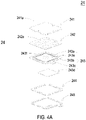
FIG. 4A is a schematic exploded view illustrating the actuator of the gas sensing module of the gas detecting device according to the embodiment of the present disclosure; -
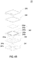
FIG. 4B is a schematic exploded view illustrating the actuator ofFIG. 4A and taken along another viewpoint; -
FIG. 5A is a schematic cross-sectional view illustrating the actuator ofFIG. 4A ; -
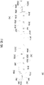
FIGS. 5B ,5C and5D schematically illustrate the actions of the actuator ofFIG. 5A ; -
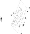
FIG. 6 schematically illustrates the flowing direction of the gas in the gas sensing module of the gas detecting device according to the embodiment of the present disclosure; -
FIG. 7 is an enlarged fragmentary side view illustrating the flowing direction of the gas in the gas sensing module of the gas detecting device according to the embodiment of the present disclosure; -
FIG. 8 is a schematic perspective view illustrating a particulate measuring module and a control module of the gas detecting device according to the embodiment of the present disclosure; and -
FIG. 9 is a functional block diagram illustrating the architecture of gas detecting device according to the embodiment of the present disclosure. - The present disclosure will now be described more specifically with reference to the following embodiments. It is to be noted that the following descriptions of preferred embodiments of this disclosure are presented herein for purpose of illustration and description only. It is not intended to be exhaustive or to be limited to the precise form disclosed.
- Please refer to
FIGS. 1 to 3C ,FIG. 8 andFIG. 9 . The present discourse provides a gas detecting device including at least onemain body 1, at least onegas sensing module 2, at least oneparticulate measuring module 3, at least onecontrol module 4, at least one length L, at least one width W, at least one height H, at least onechamber 11, at least onefirst inlet 12, at least onesecond inlet 13, at least oneoutlet 14, at least onecompartment body 21, at least one carryingplate 22, at least onesensor 23, at least oneactuator 24, at least onepartition plate 211, at least onefirst compartment 212, at least onesecond compartment 213, at least onenotch 214, at least oneopening 215, at least oneoutlet aperture 216, at least oneinlet channel 31, at least oneoutlet channel 32, at least one particulate detector, at least one monitoring value and at least oneexternal connection device 5. The number of themain body 1, thegas sensing module 2, theparticulate measuring module 3, thecontrol module 4, the length L, the width W, the height H, thechamber 11, thefirst inlet 12, thesecond inlet 13, theoutlet 14, thecompartment body 21, the carryingplate 22, thesensor 23, theactuator 24, thepartition plate 211, thefirst compartment 212, thesecond compartment 213, thenotch 214, theopening 215, theoutlet aperture 216, theinlet channel 31, theoutlet channel 32, the particulate detector, the monitoring value and theexternal connection device 5 is exemplified by one for each in the following embodiments but not limited thereto. It is noted that each of themain body 1, thegas sensing module 2, theparticulate measuring module 3, thecontrol module 4, the length L, the width W, the height H, thechamber 11, thefirst inlet 12, thesecond inlet 13, theoutlet 14, thecompartment body 21, the carryingplate 22, thesensor 23, theactuator 24, thepartition plate 211, thefirst compartment 212, thesecond compartment 213, thenotch 214, theopening 215, theoutlet aperture 216, theinlet channel 31, theoutlet channel 32, the particulate detector, the monitoring value and theexternal connection device 5 can also be provided in plural numbers. - Please refer to
FIGS. 1A to 1D andFIG. 2 . The present disclosure provides a gas detecting device. The gas detecting device includes amain body 1, agas sensing module 2, aparticulate measuring module 3 and acontrol module 4. In order to make the gas detecting device slim and portable, the structure of the gas detecting device is specially designed to be held easily, less prone to slip off the grasp, and carried around conveniently for the user. In this embodiment, themain body 1 may be a thinned cuboid body with a portable size. The portable size is defined by a length L, a width W and a height H. Thegas sensing module 2, theparticulate measuring module 3 and thecontrol module 4 are disposed in themain body 1 by an optimal arrangement manner. The size of themain body 1 is specially designed as follows so as to achieve the optimal arrangement: the length L of themain body 1 is in the range between 92 mm and 102 mm, the width W of themain body 1 is in the range between 41 mm and 61 mm, and the height H of themain body 1 is in the range between 19 mm and 23 mm. Preferably, the length L is 97 mm, the width W is 51 mm, and the height H is 21 mm. Consequently, the gas detecting device is held easily, less prone to slip off the grasp, and carried around conveniently for the user. Moreover, achamber 11 is formed in the interior of themain body 1. Themain body 1 has afirst inlet 12, asecond inlet 13 and anoutlet 14, which are in fluid communication with thechamber 11. - Please refer to
FIG. 2 andFIGS. 3A to 3C , thegas sensing module 2 is disposed in thechamber 11. In this embodiment, thegas sensing module 2 includes acompartment body 21, a carryingplate 22, asensor 23 and anactuator 24. Thecompartment body 21 is located under thefirst inlet 12 of themain body 1. Thecompartment body 21 includes apartition plate 211, and the interior of thecompartment body 21 is divided into afirst compartment 212 and asecond compartment 213 by thepartition plate 211. Thepartition plate 211 has anotch 214 for allowing thefirst compartment 212 and thesecond compartment 213 to be in fluid communication with each other. Thefirst compartment 212 has anopening 215. Thesecond compartment 213 has anoutlet aperture 216. The bottom of thecompartment body 21 has anaccommodation recess 217. Theaccommodation recess 217 allows the carryingplate 22 to be partially received and positioned therein, so that the bottom of thecompartment body 21 is covered by the carryingplate 22. The edge of the bottom of thecompartment body 21 is sealed by the carryingplate 22. The carryingplate 22 has anopening 221. Thesensor 23 is packaged on and electrically connected to the carryingplate 22. In such way, the carryingplate 22 is assembled on the bottom of thecompartment body 21. Theopening 221 is aligned with theoutlet aperture 216 of thesecond compartment 213. Thesensor 23 penetrates theopening 215 of thefirst compartment 212 and is disposed within thefirst compartment 212 for measuring the gas within thefirst compartment 212. Theactuator 24 is disposed within thesecond compartment 213. Since theactuator 24 in thesecond compartment 213 and thesensor 23 in thefirst compartment 212 are separated from each other by thepartition plate 211, the heat generated from theactuator 24 is blocked by thepartition plate 211 while theactuator 24 is actuated. In such way, the detection result of thesensor 23 is not adversely affected. Moreover, theactuator 24 covers the bottom of thesecond compartment 213 and is actuated to generate the flow of gas. The gas is transported through theoutlet aperture 216 of thesecond compartment 213, and then the gas is transported through theopening 221 of the carryingplate 22 and discharged from thecompartment body 21. That is, the gas is transported and then discharged into the environment outside thecompartment body 21 via theoutlet aperture 216 and theopening 221. - Please refer to
FIGS. 3A to 3C again. In an embodiment, the carryingplate 22 may be a circuit board and includes aconnector 222 disposed thereon for allowing a flexible circuit board (not shown) to be inserted thereinto. Consequently, the carryingplate 22 is electrically connected to and in signal communication with the flexible circuit board through theconnector 222. - Please refer to
FIGS. 4A ,4B and5A . In an embodiment, theactuator 24 is a gas pump. Theactuator 24 includes agas inlet plate 241, aresonance plate 242, apiezoelectric actuator 243, aninsulation plate 244 and a conductingplate 245, which are stacked on each other sequentially. Thegas inlet plate 241 has at least oneinlet aperture 241a, at least oneconvergence channel 241b and aconvergence chamber 241c. The number of theinlet aperture 241a is the same as the number of theconvergence channel 241b. In this embodiment, the number of theinlet apertures 241a and theconvergence channels 241b is exemplified by four for each but not limited thereto. The fourinlet apertures 241a penetrate through the fourconvergence channels 241b respectively, and the fourconvergence channels 241b converge to theconvergence chamber 241c. - The
resonance plate 242 is assembled on thegas inlet plate 241 by attaching. Theresonance plate 242 has a central aperture242a, amovable part 242b and afixed part 242c. Thecentral aperture 242a is located in the center of theresonance plate 242 and is aligned with theconvergence chamber 241c of thegas inlet plate 241. The region of theresonance plate 242 around thecentral aperture 242a and corresponding to theconvergence chamber 241c is themovable part 242b. The region of the periphery of theresonance plate 242 securely attached on thegas inlet plate 241 is thefixed part 242c. - The
piezoelectric actuator 243 includes asuspension plate 243a, anouter frame 243b, at least oneconnection component 243c, apiezoelectric element 243d, at least onevacant space 243e and abulge 243f. Thesuspension plate 243a is square, and has afirst surface 2431a and asecond surface 2432a. Thefirst surface 2431a and thesecond surface 2432a are opposed to each other. Theouter frame 243b is disposed around the periphery of thesuspension plate 243a. Theouter frame 243b has acoupling surface 2431b and abottom surface 2432b opposite to thecoupling surface 2431b. The at least oneconnection component 243c is connected between thesuspension plate 243a and theouter frame 243b for elastically supporting thesuspension plate 243a. The at least onevacant space 243e is formed among thesuspension plate 243a, theouter frame 243b and the at least oneconnection component 243c for allowing the gas to flow through. Thebulge 243f is formed on thefirst surface 2431a of thesuspension plate 243a. In this embodiment, the formation of thebulge 243f may be completed by using an etching process, in which the region between the periphery of thebulge 243f and the periphery of thesuspension plate 243a is partially removed. Accordingly, thebulge 243f of thesuspension plate 243a is higher than thefirst surface 2431a, and a stepped structure is formed. - As shown in
FIG. 5A , in this embodiment, thesuspension plate 243a may be processed by a stamping method, by which theouter frame 243b, theconnection component 243c, and thesuspension plate 243a have a concave profile in cross section. The stamping method makes the suspension plate 33a disposed further away from the resonance plate 32 a distance D, which can be adjusted by the at least oneconnection component 243c formed between thesuspension plate 243a and theouter frame 243b. Consequently, thetop surface 2431f of thebulge 243f and thefirst surface 2431a of thesuspension plate 243a are not coplanar with thecoupling surface 2431b of theouter frame 243b. Namely, thetop surface 2431f of thebulge 243f and thefirst surface 2431a are lower than thecoupling surface 2431b of theouter frame 243b, and thesecond surface 2432a of thesuspension plate 243a is lower than thebottom surface 2432b of theouter frame 243b. In the embodiment, thepiezoelectric element 243d is attached on thesecond surface 2432a of thesuspension plate 243a and aligned with thebulge 243f. In response to an applied voltage, thepiezoelectric element 243d is deformed by the piezoelectric effect to drive thesuspension plate 243a to undergo the bending vibration. By utilizing a small amount of adhesive applied to thecoupling surface 2431b of theouter frame 243b, thepiezoelectric actuator 243 is attached to thefixed part 242c of theresonance plate 242 after heat pressing, thereby assembling thepiezoelectric actuator 243 and theresonance plate 242 in combination. In addition, theinsulation plate 244 and the conductingplate 245 are both thin frame-shaped sheets, which are sequentially stacked under thepiezoelectric actuator 243. In the embodiment, theinsulation plate 244 is attached to thebottom surface 2432b of theouter frame 243b of thepiezoelectric actuator 243. - Please refer to
FIG. 5A again. After thegas inlet plate 241, theresonance plate 242, thepiezoelectric actuator 243, theinsulation plate 244 and the conductingplate 245 of theactuator 24 are stacked and assembled sequentially, a chamber gap g is formed between thefirst surface 2431a of thesuspension plate 243a and theresonance plate 242. Since the distance between thesuspension plate 243a and theresonance plate 242 will influence the transportation effect of theactuator 24, it is very important to maintain the chamber gap g for providing a stable transportation efficiency of theactuator 24. Thesuspension plate 243a of theactuator 24 is processed by the stamping method as described above, and it makes thesuspension plate 243a disposed further away from theresonance plate 32. Consequently, thefirst surface 2431a of thesuspension plate 243a and thecoupling surface 2431b of theouter frame 243b are non-coplanar. Namely, thetop surface 2431f and thefirst surface 2431a of thesuspension plate 243a are lower than thecoupling surface 2431b of theouter frame 243b, and thesecond surface 2432a of thesuspension plate 243a is lower than thebottom surface 2432b of theouter frame 243b. In this way, the entire structure may be improved by adopting the stamping method to process thesuspension plate 243a. The space between thesuspension plate 243a of thepiezoelectric actuator 243 and theresonance plate 242 is adjustable due to the stamping method, by which the adjustable chamber gap g is realized. That is, the design of achamber space 246 is improved by processing thesuspension plate 243a of thepiezoelectric actuator 243 to be disposed further away from theresonance plate 242. The desired chamber gap g can be satisfied by simply adjusting the distance D, as described above. It simplifies the structural design regarding the adjustment of the chamber gap g, and it also achieves the advantages of simplifying the process and shortening the processing time. -
FIGS. 5B and5D are schematic views illustrating actions of the actuator ofFIG. 5A . Please refer toFIG. 5B firstly. When thepiezoelectric element 243d of thepiezoelectric actuator 243 is deformed in response to an applied voltage, thesuspension plate 243a is driven to displace in the direction away from thegas inlet plate 241. In that, the volume of thechamber space 246 is increased, a negative pressure is formed in thechamber space 246, and the gas in theconvergence chamber 241c is inhaled into thechamber space 246. At the same time, theresonance plate 242 is in resonance and thus displaced synchronously in the direction away from thegas inlet plate 241. Thereby, the volume of theconvergence chamber 241c is increased. Since the gas in theconvergence chamber 241c flows into thechamber space 246, theconvergence chamber 241c is also in a negative pressure state, and the gas is sucked into theconvergence chamber 241c by flowing through theinlet aperture 241a and theconvergence channel 241b. Please refer toFIG. 5C , thepiezoelectric element 243d drives thesuspension plate 243a to be displaced toward thegas inlet plate 241 to compress thechamber space 246. Thus, the gas contained in thechamber space 246 is transported to flow through thevacant spaces 243e in the direction away from thegas inlet plate 241 and it achieves the effect of gas transportation. Similarly, theresonance plate 242 is actuated in resonance by thesuspension plate 243a and displaced toward thegas inlet plate 241. Thus, the gas contained inconvergence chamber 241c is compressed synchronously to flow to thechamber space 246. Finally, as shown inFIG. 5D . When thesuspension plate 243a is driven to displace in the direction away from thegas inlet plate 241, theresonance plate 242 is also driven to displace in the direction away from thegas inlet plate 241 at the same time. In that, theresonance plate 242 pushes the gas in thechamber space 246 toward thevacant space 243e, and the volume of theconvergence chamber 241c is increased. Thus, the gas can continuously flow through theinlet aperture 241a and theconvergence channel 241b and be converged in theconvergence chamber 241c. By repeating the actions shown in the above continuously, theactuator 24 can continuously inhale the gas through theinlet aperture 241a and transport the gas through thevacant spaces 243e in the direction away from thegas inlet plate 241. It achieves the effect of transporting the gas to thesensor 23 for detecting, thereby improving the detecting efficiency. - Please refer to
FIG. 5A again. In another embodiment, theactuator 24 can be a micro-electromechanical-systems gas pump formed by a micro-electromechanical-systems method. Thegas inlet plate 241, theresonance plate 242, thepiezoelectric actuator 243, theinsulation plate 244, and the conductingplate 245 can all be made through a surface micromachining technique to reduce the volume of theactuator 24. - Please refer to
FIGS. 6 and7 . Thegas sensing module 2 is embedded in thechamber 11 of themain body 1.FIG. 6 schematically illustrates the flowing direction of the gas in thegas sensing module 2 disposed in themain body 1. For ease of discussion, themain body 1 is not clearly shown. Thefirst inlet 12 of themain body 1 is aligned with thefirst compartment 212 of thecompartment body 21. Thefirst inlet 12 of themain body 1 and thesensor 23 within thefirst compartment 212 are not aligned with each other. That is, thefirst inlet 12 is not disposed directly above thesensor 23, and thefirst inlet 12 and thesensor 23 are misaligned with each other. When theactuator 24 is actuated, a negative pressure is formed in thesecond compartment 213, so that the ambient gas around themain body 1 is inhaled into thefirst compartment 212 through thefirst inlet 12 and thesensor 23 within thefirst compartment 212 measures the gas flowing through the surface of thesensor 23 so as to monitor air quality around themain body 1. As theactuator 24 is actuated continuously, the gas is transported to thesecond compartment 213 through thenotch 214 of thepartition plate 211, and then the gas is discharged from thecompartment body 21 through theoutlet aperture 216 and theopening 221 of the carryingplate 22. In such way, the gas is guided along a single direction A (illustrated inFIG. 6 ). - In this embodiment, the
sensor 23 can be at least one selected from the group consisting of an oxygen sensor, a carbon monoxide sensor, a carbon dioxide sensor, a temperature sensor, an ozone sensor, a volatile organic compound sensor and combinations thereof. In some embodiments, thesensor 23 can be at least one selected from the group consisting of a bacterial sensor, a virus sensor, a microorganism sensor and combinations thereof. - From the above descriptions, the
gas sensing module 2 of the gas detecting device is capable of monitoring the air quality in the environment in any time. As theactuator 24 is actuated, the gas is guided into the interior of thegas sensing module 2 rapidly and stably, so that the sensing efficacy of thesensor 23 is enhanced. Since thesensor 23 in thefirst compartment 212 and theactuator 24 in thesecond compartment 213 are separated from each other by thepartition plate 211, the heat generated from theactuator 24 is blocked by thepartition plate 211. In such way, the detection result of thesensor 23 is not adversely affected by the heat and other components within the gas detecting device. In other words, the gas detecting device can monitor the air quality in the environment rapidly and accurately at anytime and anywhere. -
FIG. 8 is a schematic perspective view illustrating a particulate measuring module and a control module of the gas detecting device according to the embodiment of the present disclosure. In an embodiment, the gas detecting device further includes aparticulate measuring module 3 for detecting the particulates in the gas. Theparticulate measuring module 3 is disposed in thechamber 11 of themain body 1. As shown inFIG. 8 , theparticulate measuring module 3 includes aninlet channel 31, anoutlet channel 32 and a particulate detector (not shown). The particulate detector is disposed within theparticulate measuring module 3. Theinlet channel 31 is aligned with thesecond inlet 13 of themain body 1. Theoutlet channel 32 is aligned with theoutlet 14 of themain body 1. After the ambient gas is introduced into theparticulate measuring module 3 through theinlet channel 31, the concentration of the particulates in the gas is measured by the particulate detector. Then, the gas is discharged from theoutlet channel 32 and finally discharged through theoutlet 14 into the environment outside themain body 1. In this embodiment, the particulate detector may be a PM2.5 sensor. - Please refer to
FIGS. 8 and9 . In this embodiment, thecontrol module 4 further includes aprocessor 41 and atransmission module 42. Theprocessor 41 is electrically connected to thetransmission module 42, thegas sensing module 2 and theparticulate measuring module 3 for controlling actuations of thetransmission module 42, thesensor 23 and theactuator 24 of thegas sensing module 2, and the particulate detector of theparticulate measuring module 3. Theprocessor 41 analyzes detecting results from thesensor 23 and the particulate detector, and converters the analysis result into a monitoring value to be stored. Thetransmission module 42 transmits the monitoring value to anexternal connection device 5 for storage. Theexternal connection device 5 may be at least one selected from the group consisting of a cloud system, a portable electronic device, a computer system, a display device and combinations thereof. Theexternal connection device 5 is configured to display information carried by the monitoring value and announce an alert. - In this embodiment, the
transmission module 42 transmits the monitoring value to theexternal connection device 5 via a wired transmission technology or a wireless transmission technology. Thetransmission module 42 is a wired transmission module, which may be at least one selected from the group consisting of a USB (Universal Serial Bus) transmission module, a mini-USB transmission module (see the reference number C of FIG. ID), a micro-USB transmission module and combinations thereof. Alternatively, thetransmission module 42 is a wireless transmission module, which may be at least one selected from the group consisting of a Wi-Fi transmission module, a Bluetooth transmission module, a radio frequency identification (RFID) transmission module, a near field communication (NFC) transmission module and combinations thereof. Thecontrol module 4 further includes abattery 43. Thebattery 43 is configured to store and output the electric energy. Moreover, thebattery 43 can be connected to apower supply device 6 for receiving and storing the electric energy from thepower supply device 6. Thebattery 43 provides theprocessor 41 with the electric energy, and theprocessor 41 issues electric signal and driving signal to control actuations of thegas sensing module 2 and theparticulate measuring module 3. The electric energy from thepower supply device 6 is transmitted to thebattery 43 via the wired transmission technology or the wireless transmission technology. - From the above descriptions, the present disclosure provides the gas detecting device. The gas sensing module of the gas detecting device is capable of monitoring the air quality in the environment at any time. When the actuator is actuated, the gas is guided into the interior of the gas sensing module quickly and stably, so that the efficacy of the gas sensing module is enhanced. Moreover, the actuator in the second compartment and the sensor in the first compartment are separated from each other by the partition plate, the heat generated from the actuator is blocked by the partition plate to reduce the influence on the sensor while the sensor monitors the air quality. In such way, the detection result of the sensor is not adversely affected by the heat and other components (e.g., the control module) within the gas detecting device. Consequently, the gas detecting device can monitor the air quality in the environment rapidly and accurately at anytime and anywhere. Furthermore, the gas detecting device further includes a particulate measuring module for measuring the concentration of the particulates in the gas from the external environment and transmitting the monitoring value to the external connection device. The external connection device can obtain the information carried by the monitoring value and announce an alert to the user in the environment immediately so that the user can take preventive measures or escape immediately, and the influence and injury to the human health caused by the gas exposure in the environment will be prevented.
Claims (14)
- A gas detecting device, comprising:a main body (1) having a portable size defined by a length (L), a width (W) and a height (H), and having a chamber (11), a first inlet (12), a second inlet (13) and an outlet (14), wherein the chamber (11) is formed within the main body (1), and the first inlet (12), the second inlet (13) and the outlet (14) are in fluid communication with the chamber (11);a particulate measuring module (3) disposed within the chamber (11) of the main body (1), and comprising an inlet channel (31), an outlet channel (32) and a particulate detector, wherein the particulate detector is disposed within the particulate measuring module (3), the inlet channel (31) is aligned with the second inlet (13) of the main body (1), and the outlet channel (32) is aligned with the outlet (14) of the main body (1), wherein the gas can be introduced into the particulate measuring module (3) through the inlet channel (31), a concentration of particulates in the gas can be measured by the particulate detector and the gas can be discharged from the outlet channel (32); anda control module (4) configured to control actuations of a gas sensing module (2) and the particulate measuring module (3), and convert detection results of the gas sensing module (2) and the particulate measuring module (3) into a monitoring value to be stored and transmitted to an external connection device (5) for storage, characterized in that the gas detecting device comprises:
the gas sensing module (2) comprising a compartment body (21), a carrying plate (22), a sensor (23) and an actuator (24), wherein the compartment body (21) is located under the first inlet (12) of the main body (1) and has a partition plate (211) disposed therein to divide an interior of the compartment body (21) into a first compartment (212) and a second compartment (213), and the partition plate (211) has a notch (214) for allowing the first compartment (212) and the second compartment (213) to be in fluid communication with each other, wherein the first compartment (212) has an opening (215), the second compartment (213) has an outlet aperture (216), the carrying plate (22) is assembled on a bottom of the compartment body (21) and is packaged on and electrically connected to the sensor (23), the sensor (23) penetrates the opening (215) and is disposed within the first compartment (212), the actuator (24) is disposed within the second compartment (213), and the actuator (24) and the sensor (23) are separated from each other, wherein the actuator (24) is actuated to introduce ambient gas into the gas sensing module (2) through the first inlet (12), and the gas is measured by the sensor (23) and discharged from the outlet (14) of the compartment body (21). - The gas detecting device according to claim 1, wherein the length (L) of the main body (1) is in a range between 92 mm and 102 mm, the width (W) of the main body (1) is in a range between 41 mm and 61 mm, and the height (H) of the main body (1) is in a range between 19 mm and 23 mm so as to form the portable size.
- The gas detecting device according to claim 2, wherein the length (L) of the main body (1) is 97 mm, the width (W) of the main body (1) is 51 mm, and the height (H) of the main body (1) is 21 mm.
- The gas detecting device according to claim 1, wherein the bottom of the compartment body (21) has an accommodation recess (217) for allowing the carrying plate (22) to be partially received and positioned within so that the bottom of the compartment body (21) is covered by the carrying plate (22), wherein the carrying plate (22) has an opening (221) aligned with the outlet aperture (216) of the second compartment (213) so that the gas is discharged from the compartment body (21) through the outlet aperture (216) of the second compartment (213) and the opening (221) of the carrying plate (22).
- The gas detecting device according to claim 1, wherein the sensor (23) is a gas sensor.
- The gas detecting device according to claim 5, wherein the gas sensor is at least one selected from a group consisting of an oxygen sensor, a carbon monoxide sensor, a carbon dioxide sensor, a volatile organic compound sensor, and combinations thereof.
- The gas detecting device according to claim 1, wherein the sensor (23) is at least one selected from a group consisting of a bacterial sensor, a virus sensor, a microorganism sensor, and combinations thereof.
- The gas detecting device according to claim 1, wherein the actuator (24) is a micro-electromechanical-systems gas pump.
- The gas detecting device according to claim 1, wherein the actuator (24) is a gas pump, and the gas pump comprises:a gas inlet plate (241) having at least one inlet aperture (241a), at least one convergence channel (241b) and a convergence chamber (241c), wherein the at least one inlet aperture (241a) allows the gas to flow in, and the at least one convergence channel (241c) is aligned with the at least one inlet aperture (241a) and guides the gas from the inlet aperture (241a) toward the convergence chamber (241c);a resonance plate (242) having a central aperture (242a) and a movable part (242b), wherein the central aperture (242a) is aligned with the convergence chamber (241c) and the movable part (242b) surrounds the central aperture (242a); anda piezoelectric actuator (243) aligned with the resonance plate (242);wherein a chamber space (246) is formed between the resonance plate (242) and the piezoelectric actuator (243), so that the gas from the at least one inlet aperture (241a) of the gas inlet plate (241) is converged to the convergence chamber (241c) along the at least one convergence channel (241b) and flows into the chamber space (246) through the central aperture (242a) of the resonance plate (242) when the piezoelectric actuator (24) is driven, whereby the gas is further transported through a resonance between the piezoelectric actuator (243) and the movable part (242b) of the resonance plate (242).
- The gas detecting device according to claim 9, wherein the piezoelectric actuator (243) comprises:a suspension plate (243a) having a first surface (2431a), a second surface (2432a) and a bulge (243f), wherein the bulge (243f) is disposed on the first surface (2431a);an outer frame (243b) arranged around the suspension plate (243a) and having a coupling surface (2431b);at least one connection component (243c) connected between the suspension plate (243a) and the outer frame (243b) for elastically supporting the suspension plate (243a); anda piezoelectric element (243d) attached on the second surface (2432a) of the suspension plate (243a) to drive the suspension plate (243a) to undergo the bending vibration in response to an applied voltage;wherein the at least one connection component (243c) is formed between the suspension plate (243a) and the outer frame (243b), the first surface (2431a) of the suspension plate (243a) and the coupling surface (2431b) of the outer frame (243b) are non-coplanar, and a chamber gap (g) is maintained between the first surface (2431a) of the suspension plate (243a) and the resonance plate (242).
- The gas detecting device according to claim 1, wherein the control module (4) comprises a processor (41) and a transmission module (42), wherein the processor (41) controls actuations of the transmission module (4), the sensor (23) of the gas sensing module (2) and the particulate detector of the particulate measuring module (3), the processor (41) analyzes and converts the detection results of the sensor (23) and the particulate detector into the monitoring value, and the transmission module (42) transmits the monitoring value to the external connection device (5) for storage.
- The gas detecting device according to claim 1, wherein the external connection device (5) is at least one selected from the group consisting of a cloud system, a portable device, a computer system, and combinations thereof.
- The gas detecting device according to claim 11, wherein the control module (4) further comprises a battery (43) configured to store and output electric power, the battery (43) is electrically connected to a power supply device (6) for receiving and storing electric power from the power supply device (6), the battery (43) provides the processor (41) with the electric power, and the processor (41) provides the gas sensing module (2) and the particulate measuring module (3) with electric signal and driving signal.
- The gas detecting device according to claim 1, wherein the particulate detector is a PM2.5 sensor.
Applications Claiming Priority (1)
| Application Number | Priority Date | Filing Date | Title |
|---|---|---|---|
| TW107114585A TWI710758B (en) | 2018-04-27 | 2018-04-27 | Gas detecting device |
Publications (2)
| Publication Number | Publication Date |
|---|---|
| EP3570023A1 EP3570023A1 (en) | 2019-11-20 |
| EP3570023B1 true EP3570023B1 (en) | 2022-10-12 |
Family
ID=65440914
Family Applications (1)
| Application Number | Title | Priority Date | Filing Date |
|---|---|---|---|
| EP19157277.5A Active EP3570023B1 (en) | 2018-04-27 | 2019-02-14 | Gas detecting device |
Country Status (4)
| Country | Link |
|---|---|
| US (1) | US10969322B2 (en) |
| EP (1) | EP3570023B1 (en) |
| JP (1) | JP7166954B2 (en) |
| TW (1) | TWI710758B (en) |
Families Citing this family (21)
| Publication number | Priority date | Publication date | Assignee | Title |
|---|---|---|---|---|
| US11415491B2 (en) * | 2018-09-27 | 2022-08-16 | Apple Inc. | Pumping mechanism for gas sensors |
| US10935531B2 (en) * | 2018-10-12 | 2021-03-02 | Hamilton Sundstrand Corporation | Integrated sensor packages |
| TWI724386B (en) * | 2019-03-15 | 2021-04-11 | 研能科技股份有限公司 | Particle detecting device |
| TWI738175B (en) * | 2020-01-08 | 2021-09-01 | 研能科技股份有限公司 | Home device capable of gas detection |
| TWI747132B (en) * | 2020-01-08 | 2021-11-21 | 研能科技股份有限公司 | Health detection device having gas detection function |
| CN113550891B (en) * | 2020-04-24 | 2022-10-25 | 研能科技股份有限公司 | Actuation sensing module |
| US11760169B2 (en) | 2020-08-20 | 2023-09-19 | Denso International America, Inc. | Particulate control systems and methods for olfaction sensors |
| US12269315B2 (en) | 2020-08-20 | 2025-04-08 | Denso International America, Inc. | Systems and methods for measuring and managing odor brought into rental vehicles |
| US12251991B2 (en) | 2020-08-20 | 2025-03-18 | Denso International America, Inc. | Humidity control for olfaction sensors |
| US11881093B2 (en) | 2020-08-20 | 2024-01-23 | Denso International America, Inc. | Systems and methods for identifying smoking in vehicles |
| US11813926B2 (en) | 2020-08-20 | 2023-11-14 | Denso International America, Inc. | Binding agent and olfaction sensor |
| US11636870B2 (en) | 2020-08-20 | 2023-04-25 | Denso International America, Inc. | Smoking cessation systems and methods |
| US11932080B2 (en) | 2020-08-20 | 2024-03-19 | Denso International America, Inc. | Diagnostic and recirculation control systems and methods |
| US11828210B2 (en) | 2020-08-20 | 2023-11-28 | Denso International America, Inc. | Diagnostic systems and methods of vehicles using olfaction |
| US12377711B2 (en) | 2020-08-20 | 2025-08-05 | Denso International America, Inc. | Vehicle feature control systems and methods based on smoking |
| US11760170B2 (en) | 2020-08-20 | 2023-09-19 | Denso International America, Inc. | Olfaction sensor preservation systems and methods |
| US12017506B2 (en) | 2020-08-20 | 2024-06-25 | Denso International America, Inc. | Passenger cabin air control systems and methods |
| KR102710509B1 (en) * | 2021-02-09 | 2024-09-27 | 주식회사 지에버 | Portable gas measuring device using semiconductor gas sensor and its operation method |
| CN113484472B (en) * | 2021-07-05 | 2023-05-05 | 郑州水伟环境科技有限公司 | Intelligent multichannel gas self-adaptive calibration detection chip |
| JP7796522B2 (en) | 2021-12-22 | 2026-01-09 | シャープセミコンダクターイノベーション株式会社 | Detection device and electronic device |
| TWI881369B (en) * | 2023-06-20 | 2025-04-21 | 研能科技股份有限公司 | Gas detection device |
Family Cites Families (9)
| Publication number | Priority date | Publication date | Assignee | Title |
|---|---|---|---|---|
| JP2007248401A (en) * | 2006-03-20 | 2007-09-27 | Junichiro Yoshida | Humidity sensor and its structure |
| WO2008024138A1 (en) * | 2006-08-23 | 2008-02-28 | Georgia Tech Research Corporation | Fluidically-assisted sensor systems for fast sensing of chemical and biological substances |
| KR102161546B1 (en) * | 2014-02-05 | 2020-10-05 | 삼성전자 주식회사 | Electronic device and operation method thereof |
| US9955244B2 (en) * | 2015-05-27 | 2018-04-24 | Apple Inc. | Electronic device with speaker enclosure sensor |
| TWI681119B (en) * | 2016-01-29 | 2020-01-01 | 研能科技股份有限公司 | Micro-fluid control device |
| US10584695B2 (en) * | 2016-01-29 | 2020-03-10 | Microjet Technology Co., Ltd. | Miniature fluid control device |
| US10488305B2 (en) * | 2016-06-23 | 2019-11-26 | Colorado State University Research Foundation | Portable air sampling device |
| TWM553417U (en) * | 2017-08-21 | 2017-12-21 | Microjet Technology Co Ltd | Apparatus having actuating sensor module within |
| TWM558353U (en) * | 2018-01-12 | 2018-04-11 | Microjet Technology Co Ltd | Gas detecting device |
-
2018
- 2018-04-27 TW TW107114585A patent/TWI710758B/en active
-
2019
- 2019-02-14 EP EP19157277.5A patent/EP3570023B1/en active Active
- 2019-02-15 US US16/277,426 patent/US10969322B2/en active Active
- 2019-02-21 JP JP2019029661A patent/JP7166954B2/en active Active
Also Published As
| Publication number | Publication date |
|---|---|
| TWI710758B (en) | 2020-11-21 |
| EP3570023A1 (en) | 2019-11-20 |
| US10969322B2 (en) | 2021-04-06 |
| JP7166954B2 (en) | 2022-11-08 |
| JP2019215315A (en) | 2019-12-19 |
| TW201945706A (en) | 2019-12-01 |
| US20190331582A1 (en) | 2019-10-31 |
Similar Documents
| Publication | Publication Date | Title |
|---|---|---|
| US10969322B2 (en) | Gas detecting device | |
| US10955320B2 (en) | Gas detecting device for monitoring air quality in a gas transportation device | |
| US10935529B2 (en) | Portable device including a gas detecting module for monitoring environmental air conditions | |
| US20200156084A1 (en) | Gas purifying device | |
| EP3499213B1 (en) | Particulate matter measuring device | |
| US20190064104A1 (en) | Actuating and sensing module | |
| US11255323B2 (en) | Driving system for actuating and sensing module | |
| EP3517930A1 (en) | Gas detecting device | |
| EP3447453A2 (en) | Device having actuating and sensing module | |
| US10908137B2 (en) | Actuating and sensing module | |
| EP3428640B1 (en) | Actuating and sensing module | |
| EP3431956B1 (en) | Actuating and sensing module | |
| EP3508847A1 (en) | Gas detecting device | |
| TWM567361U (en) | Gas detection device | |
| US10994160B2 (en) | Driving and information transmitting system for air-filtering protection device | |
| CN208188080U (en) | Gas detection device | |
| TWM565305U (en) | Gas detecting device | |
| US20210109004A1 (en) | Gas-detectable casing of portable device | |
| EP3441117A1 (en) | Air-filtering protection device | |
| TWM568360U (en) | Gas detection device | |
| TWM567363U (en) | Gas detection device | |
| EP3434993A1 (en) | Air quality notification and processing system | |
| US11686715B2 (en) | Mobile power device capable of detecting gas | |
| US11733143B2 (en) | External gas detecting device | |
| US10864473B2 (en) | Air-filtering protection device |
Legal Events
| Date | Code | Title | Description |
|---|---|---|---|
| PUAI | Public reference made under article 153(3) epc to a published international application that has entered the european phase |
Free format text: ORIGINAL CODE: 0009012 |
|
| STAA | Information on the status of an ep patent application or granted ep patent |
Free format text: STATUS: THE APPLICATION HAS BEEN PUBLISHED |
|
| AK | Designated contracting states |
Kind code of ref document: A1 Designated state(s): AL AT BE BG CH CY CZ DE DK EE ES FI FR GB GR HR HU IE IS IT LI LT LU LV MC MK MT NL NO PL PT RO RS SE SI SK SM TR |
|
| AX | Request for extension of the european patent |
Extension state: BA ME |
|
| STAA | Information on the status of an ep patent application or granted ep patent |
Free format text: STATUS: REQUEST FOR EXAMINATION WAS MADE |
|
| 17P | Request for examination filed |
Effective date: 20200520 |
|
| RBV | Designated contracting states (corrected) |
Designated state(s): AL AT BE BG CH CY CZ DE DK EE ES FI FR GB GR HR HU IE IS IT LI LT LU LV MC MK MT NL NO PL PT RO RS SE SI SK SM TR |
|
| GRAP | Despatch of communication of intention to grant a patent |
Free format text: ORIGINAL CODE: EPIDOSNIGR1 |
|
| STAA | Information on the status of an ep patent application or granted ep patent |
Free format text: STATUS: GRANT OF PATENT IS INTENDED |
|
| INTG | Intention to grant announced |
Effective date: 20220504 |
|
| GRAS | Grant fee paid |
Free format text: ORIGINAL CODE: EPIDOSNIGR3 |
|
| GRAA | (expected) grant |
Free format text: ORIGINAL CODE: 0009210 |
|
| STAA | Information on the status of an ep patent application or granted ep patent |
Free format text: STATUS: THE PATENT HAS BEEN GRANTED |
|
| AK | Designated contracting states |
Kind code of ref document: B1 Designated state(s): AL AT BE BG CH CY CZ DE DK EE ES FI FR GB GR HR HU IE IS IT LI LT LU LV MC MK MT NL NO PL PT RO RS SE SI SK SM TR |
|
| REG | Reference to a national code |
Ref country code: GB Ref legal event code: FG4D |
|
| REG | Reference to a national code |
Ref country code: CH Ref legal event code: EP |
|
| REG | Reference to a national code |
Ref country code: DE Ref legal event code: R096 Ref document number: 602019020419 Country of ref document: DE |
|
| REG | Reference to a national code |
Ref country code: IE Ref legal event code: FG4D |
|
| REG | Reference to a national code |
Ref country code: AT Ref legal event code: REF Ref document number: 1524460 Country of ref document: AT Kind code of ref document: T Effective date: 20221115 |
|
| REG | Reference to a national code |
Ref country code: LT Ref legal event code: MG9D |
|
| REG | Reference to a national code |
Ref country code: NL Ref legal event code: MP Effective date: 20221012 |
|
| REG | Reference to a national code |
Ref country code: AT Ref legal event code: MK05 Ref document number: 1524460 Country of ref document: AT Kind code of ref document: T Effective date: 20221012 |
|
| PG25 | Lapsed in a contracting state [announced via postgrant information from national office to epo] |
Ref country code: NL Free format text: LAPSE BECAUSE OF FAILURE TO SUBMIT A TRANSLATION OF THE DESCRIPTION OR TO PAY THE FEE WITHIN THE PRESCRIBED TIME-LIMIT Effective date: 20221012 |
|
| PG25 | Lapsed in a contracting state [announced via postgrant information from national office to epo] |
Ref country code: SE Free format text: LAPSE BECAUSE OF FAILURE TO SUBMIT A TRANSLATION OF THE DESCRIPTION OR TO PAY THE FEE WITHIN THE PRESCRIBED TIME-LIMIT Effective date: 20221012 Ref country code: PT Free format text: LAPSE BECAUSE OF FAILURE TO SUBMIT A TRANSLATION OF THE DESCRIPTION OR TO PAY THE FEE WITHIN THE PRESCRIBED TIME-LIMIT Effective date: 20230213 Ref country code: NO Free format text: LAPSE BECAUSE OF FAILURE TO SUBMIT A TRANSLATION OF THE DESCRIPTION OR TO PAY THE FEE WITHIN THE PRESCRIBED TIME-LIMIT Effective date: 20230112 Ref country code: LT Free format text: LAPSE BECAUSE OF FAILURE TO SUBMIT A TRANSLATION OF THE DESCRIPTION OR TO PAY THE FEE WITHIN THE PRESCRIBED TIME-LIMIT Effective date: 20221012 Ref country code: FI Free format text: LAPSE BECAUSE OF FAILURE TO SUBMIT A TRANSLATION OF THE DESCRIPTION OR TO PAY THE FEE WITHIN THE PRESCRIBED TIME-LIMIT Effective date: 20221012 Ref country code: ES Free format text: LAPSE BECAUSE OF FAILURE TO SUBMIT A TRANSLATION OF THE DESCRIPTION OR TO PAY THE FEE WITHIN THE PRESCRIBED TIME-LIMIT Effective date: 20221012 Ref country code: AT Free format text: LAPSE BECAUSE OF FAILURE TO SUBMIT A TRANSLATION OF THE DESCRIPTION OR TO PAY THE FEE WITHIN THE PRESCRIBED TIME-LIMIT Effective date: 20221012 |
|
| PG25 | Lapsed in a contracting state [announced via postgrant information from national office to epo] |
Ref country code: RS Free format text: LAPSE BECAUSE OF FAILURE TO SUBMIT A TRANSLATION OF THE DESCRIPTION OR TO PAY THE FEE WITHIN THE PRESCRIBED TIME-LIMIT Effective date: 20221012 Ref country code: PL Free format text: LAPSE BECAUSE OF FAILURE TO SUBMIT A TRANSLATION OF THE DESCRIPTION OR TO PAY THE FEE WITHIN THE PRESCRIBED TIME-LIMIT Effective date: 20221012 Ref country code: LV Free format text: LAPSE BECAUSE OF FAILURE TO SUBMIT A TRANSLATION OF THE DESCRIPTION OR TO PAY THE FEE WITHIN THE PRESCRIBED TIME-LIMIT Effective date: 20221012 Ref country code: IS Free format text: LAPSE BECAUSE OF FAILURE TO SUBMIT A TRANSLATION OF THE DESCRIPTION OR TO PAY THE FEE WITHIN THE PRESCRIBED TIME-LIMIT Effective date: 20230212 Ref country code: HR Free format text: LAPSE BECAUSE OF FAILURE TO SUBMIT A TRANSLATION OF THE DESCRIPTION OR TO PAY THE FEE WITHIN THE PRESCRIBED TIME-LIMIT Effective date: 20221012 Ref country code: GR Free format text: LAPSE BECAUSE OF FAILURE TO SUBMIT A TRANSLATION OF THE DESCRIPTION OR TO PAY THE FEE WITHIN THE PRESCRIBED TIME-LIMIT Effective date: 20230113 |
|
| REG | Reference to a national code |
Ref country code: DE Ref legal event code: R097 Ref document number: 602019020419 Country of ref document: DE |
|
| PG25 | Lapsed in a contracting state [announced via postgrant information from national office to epo] |
Ref country code: SM Free format text: LAPSE BECAUSE OF FAILURE TO SUBMIT A TRANSLATION OF THE DESCRIPTION OR TO PAY THE FEE WITHIN THE PRESCRIBED TIME-LIMIT Effective date: 20221012 Ref country code: RO Free format text: LAPSE BECAUSE OF FAILURE TO SUBMIT A TRANSLATION OF THE DESCRIPTION OR TO PAY THE FEE WITHIN THE PRESCRIBED TIME-LIMIT Effective date: 20221012 Ref country code: EE Free format text: LAPSE BECAUSE OF FAILURE TO SUBMIT A TRANSLATION OF THE DESCRIPTION OR TO PAY THE FEE WITHIN THE PRESCRIBED TIME-LIMIT Effective date: 20221012 Ref country code: DK Free format text: LAPSE BECAUSE OF FAILURE TO SUBMIT A TRANSLATION OF THE DESCRIPTION OR TO PAY THE FEE WITHIN THE PRESCRIBED TIME-LIMIT Effective date: 20221012 Ref country code: CZ Free format text: LAPSE BECAUSE OF FAILURE TO SUBMIT A TRANSLATION OF THE DESCRIPTION OR TO PAY THE FEE WITHIN THE PRESCRIBED TIME-LIMIT Effective date: 20221012 |
|
| PLBE | No opposition filed within time limit |
Free format text: ORIGINAL CODE: 0009261 |
|
| STAA | Information on the status of an ep patent application or granted ep patent |
Free format text: STATUS: NO OPPOSITION FILED WITHIN TIME LIMIT |
|
| PG25 | Lapsed in a contracting state [announced via postgrant information from national office to epo] |
Ref country code: SK Free format text: LAPSE BECAUSE OF FAILURE TO SUBMIT A TRANSLATION OF THE DESCRIPTION OR TO PAY THE FEE WITHIN THE PRESCRIBED TIME-LIMIT Effective date: 20221012 Ref country code: AL Free format text: LAPSE BECAUSE OF FAILURE TO SUBMIT A TRANSLATION OF THE DESCRIPTION OR TO PAY THE FEE WITHIN THE PRESCRIBED TIME-LIMIT Effective date: 20221012 |
|
| 26N | No opposition filed |
Effective date: 20230713 |
|
| PG25 | Lapsed in a contracting state [announced via postgrant information from national office to epo] |
Ref country code: MC Free format text: LAPSE BECAUSE OF FAILURE TO SUBMIT A TRANSLATION OF THE DESCRIPTION OR TO PAY THE FEE WITHIN THE PRESCRIBED TIME-LIMIT Effective date: 20221012 |
|
| REG | Reference to a national code |
Ref country code: CH Ref legal event code: PL |
|
| REG | Reference to a national code |
Ref country code: BE Ref legal event code: MM Effective date: 20230228 |
|
| PG25 | Lapsed in a contracting state [announced via postgrant information from national office to epo] |
Ref country code: LU Free format text: LAPSE BECAUSE OF NON-PAYMENT OF DUE FEES Effective date: 20230214 Ref country code: LI Free format text: LAPSE BECAUSE OF NON-PAYMENT OF DUE FEES Effective date: 20230228 Ref country code: CH Free format text: LAPSE BECAUSE OF NON-PAYMENT OF DUE FEES Effective date: 20230228 |
|
| PG25 | Lapsed in a contracting state [announced via postgrant information from national office to epo] |
Ref country code: SI Free format text: LAPSE BECAUSE OF FAILURE TO SUBMIT A TRANSLATION OF THE DESCRIPTION OR TO PAY THE FEE WITHIN THE PRESCRIBED TIME-LIMIT Effective date: 20221012 |
|
| REG | Reference to a national code |
Ref country code: IE Ref legal event code: MM4A |
|
| PG25 | Lapsed in a contracting state [announced via postgrant information from national office to epo] |
Ref country code: IE Free format text: LAPSE BECAUSE OF NON-PAYMENT OF DUE FEES Effective date: 20230214 Ref country code: FR Free format text: LAPSE BECAUSE OF NON-PAYMENT OF DUE FEES Effective date: 20230228 |
|
| PG25 | Lapsed in a contracting state [announced via postgrant information from national office to epo] |
Ref country code: BE Free format text: LAPSE BECAUSE OF NON-PAYMENT OF DUE FEES Effective date: 20230228 |
|
| PG25 | Lapsed in a contracting state [announced via postgrant information from national office to epo] |
Ref country code: IT Free format text: LAPSE BECAUSE OF FAILURE TO SUBMIT A TRANSLATION OF THE DESCRIPTION OR TO PAY THE FEE WITHIN THE PRESCRIBED TIME-LIMIT Effective date: 20221012 |
|
| PG25 | Lapsed in a contracting state [announced via postgrant information from national office to epo] |
Ref country code: BG Free format text: LAPSE BECAUSE OF FAILURE TO SUBMIT A TRANSLATION OF THE DESCRIPTION OR TO PAY THE FEE WITHIN THE PRESCRIBED TIME-LIMIT Effective date: 20221012 |
|
| PG25 | Lapsed in a contracting state [announced via postgrant information from national office to epo] |
Ref country code: BG Free format text: LAPSE BECAUSE OF FAILURE TO SUBMIT A TRANSLATION OF THE DESCRIPTION OR TO PAY THE FEE WITHIN THE PRESCRIBED TIME-LIMIT Effective date: 20221012 |
|
| PG25 | Lapsed in a contracting state [announced via postgrant information from national office to epo] |
Ref country code: CY Free format text: LAPSE BECAUSE OF FAILURE TO SUBMIT A TRANSLATION OF THE DESCRIPTION OR TO PAY THE FEE WITHIN THE PRESCRIBED TIME-LIMIT; INVALID AB INITIO Effective date: 20190214 |
|
| PG25 | Lapsed in a contracting state [announced via postgrant information from national office to epo] |
Ref country code: HU Free format text: LAPSE BECAUSE OF FAILURE TO SUBMIT A TRANSLATION OF THE DESCRIPTION OR TO PAY THE FEE WITHIN THE PRESCRIBED TIME-LIMIT; INVALID AB INITIO Effective date: 20190214 |
|
| PG25 | Lapsed in a contracting state [announced via postgrant information from national office to epo] |
Ref country code: TR Free format text: LAPSE BECAUSE OF FAILURE TO SUBMIT A TRANSLATION OF THE DESCRIPTION OR TO PAY THE FEE WITHIN THE PRESCRIBED TIME-LIMIT Effective date: 20221012 |
|
| PGFP | Annual fee paid to national office [announced via postgrant information from national office to epo] |
Ref country code: GB Payment date: 20260115 Year of fee payment: 8 |
|
| PGFP | Annual fee paid to national office [announced via postgrant information from national office to epo] |
Ref country code: DE Payment date: 20260115 Year of fee payment: 8 |