EP3570010A1 - Measuring device, information processing device, information processing method, and program - Google Patents
Measuring device, information processing device, information processing method, and program Download PDFInfo
- Publication number
- EP3570010A1 EP3570010A1 EP17891867.8A EP17891867A EP3570010A1 EP 3570010 A1 EP3570010 A1 EP 3570010A1 EP 17891867 A EP17891867 A EP 17891867A EP 3570010 A1 EP3570010 A1 EP 3570010A1
- Authority
- EP
- European Patent Office
- Prior art keywords
- dimensional
- brdf
- display
- processing unit
- distribution
- Prior art date
- Legal status (The legal status is an assumption and is not a legal conclusion. Google has not performed a legal analysis and makes no representation as to the accuracy of the status listed.)
- Withdrawn
Links
- 230000010365 information processing Effects 0.000 title claims description 17
- 238000003672 processing method Methods 0.000 title claims description 6
- 238000005259 measurement Methods 0.000 claims abstract description 117
- 238000012545 processing Methods 0.000 claims abstract description 66
- 238000001514 detection method Methods 0.000 claims abstract description 28
- 238000000034 method Methods 0.000 claims description 16
- 230000008569 process Effects 0.000 claims description 5
- 230000008859 change Effects 0.000 claims description 3
- 230000001678 irradiating effect Effects 0.000 claims 4
- 230000006870 function Effects 0.000 description 6
- 238000004891 communication Methods 0.000 description 3
- 238000005315 distribution function Methods 0.000 description 3
- 230000002457 bidirectional effect Effects 0.000 description 2
- 239000003086 colorant Substances 0.000 description 2
- 238000010586 diagram Methods 0.000 description 2
- 230000003287 optical effect Effects 0.000 description 2
- 238000001444 catalytic combustion detection Methods 0.000 description 1
- 238000006243 chemical reaction Methods 0.000 description 1
- 239000011248 coating agent Substances 0.000 description 1
- 238000000576 coating method Methods 0.000 description 1
- 230000001419 dependent effect Effects 0.000 description 1
- 230000000694 effects Effects 0.000 description 1
- 230000004313 glare Effects 0.000 description 1
- 238000012986 modification Methods 0.000 description 1
- 230000004048 modification Effects 0.000 description 1
- 230000009467 reduction Effects 0.000 description 1
Images




Classifications
-
- G—PHYSICS
- G01—MEASURING; TESTING
- G01N—INVESTIGATING OR ANALYSING MATERIALS BY DETERMINING THEIR CHEMICAL OR PHYSICAL PROPERTIES
- G01N21/00—Investigating or analysing materials by the use of optical means, i.e. using sub-millimetre waves, infrared, visible or ultraviolet light
- G01N21/17—Systems in which incident light is modified in accordance with the properties of the material investigated
- G01N21/55—Specular reflectivity
-
- G—PHYSICS
- G01—MEASURING; TESTING
- G01N—INVESTIGATING OR ANALYSING MATERIALS BY DETERMINING THEIR CHEMICAL OR PHYSICAL PROPERTIES
- G01N21/00—Investigating or analysing materials by the use of optical means, i.e. using sub-millimetre waves, infrared, visible or ultraviolet light
- G01N21/17—Systems in which incident light is modified in accordance with the properties of the material investigated
- G01N21/55—Specular reflectivity
- G01N2021/557—Detecting specular reflective parts on sample
-
- G—PHYSICS
- G01—MEASURING; TESTING
- G01N—INVESTIGATING OR ANALYSING MATERIALS BY DETERMINING THEIR CHEMICAL OR PHYSICAL PROPERTIES
- G01N21/00—Investigating or analysing materials by the use of optical means, i.e. using sub-millimetre waves, infrared, visible or ultraviolet light
- G01N21/17—Systems in which incident light is modified in accordance with the properties of the material investigated
- G01N21/55—Specular reflectivity
- G01N21/57—Measuring gloss
-
- G—PHYSICS
- G01—MEASURING; TESTING
- G01N—INVESTIGATING OR ANALYSING MATERIALS BY DETERMINING THEIR CHEMICAL OR PHYSICAL PROPERTIES
- G01N2201/00—Features of devices classified in G01N21/00
- G01N2201/06—Illumination; Optics
- G01N2201/061—Sources
Definitions
- the present invention relates to a measurement apparatus, an information processing apparatus, an information processing method, and a program.
- PTL 1 proposes a measurement apparatus that measures a plurality of types of reflection characteristics like those described above.
- a BRDF Bidirectional Reflectance Distribution Function
- a BRDF is an index indicating with what intensity distribution light entering a surface is reflected (the intensity distribution of reflected light), and is useful to evaluate or check a reflection characteristic of light on a measurement surface. Conventionally, however, the BRDF has not been effectively used to evaluate an outer appearance associated with a reflection characteristic of a surface.
- a measurement apparatus is characterized by comprising an irradiation unit configured to obliquely irradiate a surface with light, a detection unit configured to detect an intensity distribution of reflected light from the surface, a processing unit configured to obtain a two-dimensional BRDF of the surface based on the intensity distribution, and a display unit configured to display the BRDF obtained by the processing unit, wherein the detection unit detects the intensity distribution in a direction range that includes a first direction as a direction of specular light from the surface and does not include a direction that defines, together with the first direction, an angle not less than an angle defined by the first direction and a second direction orthogonal to the surface.
- the present invention can provide a measurement apparatus advantageous in evaluating reflection characteristics of a surface.
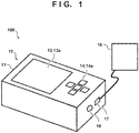
- Fig. 1 is a view showing an outer appearance of the measurement system 100.
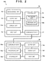
- Fig. 2 is a block diagram showing the arrangement of the measurement system 100.
- the measurement system 100 can include, for example, a measurement apparatus 10 and an information processing apparatus 18 (computer).
- the information processing apparatus 18 can include, for example, a processing unit 18a (first processing unit) including a CPU, a storage unit 18b including a memory, an output unit 18c (second processing unit) that outputs an image, an input unit 18d including a mouse and a keyboard, and a communication I/F 18e.
- the output unit 18c has a function as a display control unit that causes a display unit 18f such as an LCD to output (display) an image.
- the information processing apparatus 18 is connected to the measurement apparatus 10 (control unit 15) via the communication I/F 18e wirelessly or using a cable, and can acquire the measurement result (reflection characteristic) obtained by measurement by measurement apparatus 10.
- the measurement apparatus 10 can include, for example, a measurement unit 12, an output unit 13, an input unit 14 (operation unit), and the control unit 15, and measures a reflection characteristic of a measurement surface 20.
- the measurement unit 12 is provided in a housing 11 (inside the housing) and measures a reflection characteristic of the measurement surface 20 via an opening portion provided in the lower surface of the housing 11 while outside light is blocked by the housing 11.
- the output unit 13 outputs an image onto a display unit 13a such as an LCD provided on the upper surface of the housing. That is, the output unit 13 can function as a display control unit that causes the display unit 13a to display a reflection characteristic of a measurement surface.
- the input unit 14 receives various settings from a user via a plurality of buttons 14a provided on the upper surface of the housing 11.
- the input unit 14 includes the plurality of buttons 14a.
- the display unit 13a (display) provided on the upper surface of the housing 11 may be of a touch panel type. That is, the input unit 14 may include the touch panel type display unit 13a.
- the control unit 15 includes a processing unit 15a including a CPU and a storage unit 15b including a memory, and controls the measurement unit 12, the output unit 13, and the input unit 14.
- the measurement apparatus 10 has a power button 16 and a communication I/F 17 (USB port) provided on the housing 11 (its side surface).
- Fig. 3 is a view showing the arrangement of the measurement unit 12.
- the measurement unit 12 can include an irradiation unit that obliquely irradiates the measurement surface 20 with light and a detection unit that detects light (reflected light) reflected by the measurement surface 20.
- the irradiation unit includes a light source 12a, a lens 12b, a slit 12c, and a lens 12d.
- the detection unit can include a lens 12e and a sensor 12f.
- the light beam emitted from the light source 12a is collected in the slit 12c by the lens 12b.
- An image of the light source 12a is temporarily formed in the slit 12c to become a rectangular secondary light source.
- a light beam exiting from the slit 12c becomes a divergent light beam again and is collimated by the lens 12d to irradiate the measurement surface 20.
- Reflected light from the measurement surface 20 is formed into a reflection pattern unique to the reflection characteristics of the measurement surface 20.
- the light is then collected by the lens 12e and received by the light-receiving surface of the sensor 12f.
- the sensor 12f includes an area sensor including a two-dimensional array of photoelectric conversion elements constituted by CCDs or CMOSs.
- the intensity distribution of reflected light formed on the light-receiving surface of the sensor 12f becomes a reflection pattern whose intensity changes in accordance with an angle as indicated by the inside of the broken line in Fig. 3 .
- a plurality of types of index values representing reflection characteristics of the measurement surface 20 are obtained based on the intensity distribution of reflected light detected by the sensor 12f.
- a BRDF Bidirectional Reflectance Distribution Function
- the control unit 15 obtains the Fourier transform of a BRDF by dividing the Fourier transform of the intensity distribution of the reflected light detected by the detection unit by the Fourier transform of slit information.
- the BRDF of the measurement surface 20 can be obtained by performing the inverse Fourier transform of the obtained Fourier transform.
- a BRDF is a function representing the distribution of reflectances of a measurement surface, and represents the ratio of the luminance of reflected light to the illuminance of incident light.
- a BRDF at a given point on an object surface is dependent on both incident and reflection directions and defined as the ratio of the intensity of reflected light (diffused light) to the intensity of incident light from an irradiation direction. That is, as shown in Fig. 4 , a BRDF is an index indicating with what intensity distribution light entering a given point on a measurement surface is reflected (the intensity distribution of reflected light).
- Indices representing reflection characteristics of the measurement surface 20 include, other than a BRDF, a specular gloss, haze, DOI (Distinctness of Image), image clarity, reflectance, and undulation.
- a specular gloss represents the light amount of a specular component.
- a haze represents the distribution of light around a specular component.
- a DOI and image clarity indicate a reduction in contrast of a glare image.
- a specular gloss, haze, DOI, and image clarity can be acquired or generated (calculated) based on an intensity distribution as a blurred image of a rectangular slit instead of a BRDF as a point image distribution function. Accordingly, the control unit 15 (processing unit 15a) can obtain these index values by referring to a table or performing convolution of apparatus information based on the intensity distribution of reflected light detected by the detection unit.
- an incident angle ⁇ (a reflection angle ⁇ ' of reflected light from the measurement surface 20) of light with which the measurement surface 20 is irradiated by the irradiation unit at the time of measurement of reflection characteristics of the measurement surface 20 is defined for each reflection characteristic index (standard) according to JIS, ISO, or the like. Accordingly, when, for example, a mirror gloss is to be measured as a reflection characteristic index, the incident angle ⁇ is set to any one of 20°, 45°, 60°, 75°, and 85°. In addition, when a haze is to be measured as a reflection characteristic index, the incident angle ⁇ is set to 20° or 30°.
- the incident angle ⁇ is set to 45° or 60°.
- the incident angle ⁇ is set to 20° or 30°.
- the measurement unit 12 may be provided with a plurality of pairs of irradiation units and detection units so as to set different incident angles ⁇ or provided with a driving unit that drives an irradiation unit and a detection unit so as to change the incident angle ⁇ .
- the plurality of types of index values (BRDF, mirror gloss, haze, DOI, image clarity, and the like) obtained by the processing unit 15a in this manner are stored in the storage unit 15b in association with each other.
- the user checks the reflection tendency of light at the measurement surface 20 by referring to a BRDF indicating with what intensity distribution light entering the measurement surface 20 is reflected (the intensity distribution of reflected light).
- a BRDF indicating with what intensity distribution light entering the measurement surface 20 is reflected
- the measurement system 100 obtains the two-dimensional BRDF of the measurement surface 20 based on the intensity distribution of reflected light detected by the measurement unit 12 (detection unit), and displays the obtained two-dimensional BRDF on the display unit 13a (or the display unit 18f).
- the measurement unit 12 detects the intensity distribution of reflected light in the range of predetermined directions, of the directions of reflected light from the measurement surface 20, which include a first direction 21 as the direction of specular light from the measurement surface 20.
- the range of the predetermined directions is the range of directions that do not include a direction 23 defines, with the first direction 21, an angle ⁇ 2 equal to or more than an angle ⁇ 1 defined by the first direction 21 and a second direction 22 (normal direction) orthogonal to the measurement surface 20.
- the range of the predetermined directions is the range of directions, of the directions of reflected light from the measurement surface 20, which do not include the direction 23 defining the angle ⁇ 2 , with the direction of specular light (first direction 21), which is equal to or more than the angle ⁇ 1 (equal to or more than the reflection angle of specular light ( ⁇ 2 ⁇ ⁇ 1 )).
- the range of the predetermined directions corresponds to the range of 0° to 90° as the range of the reflection angles of reflected light from the measurement surface 20. That is, the range of the predetermined directions is the range of the directions of reflected light with reflection angles larger than 0° and smaller than 90°.
- the range of the predetermined directions includes a range on a first plane (an incident plane (for example, the drawing surface)) including specular light and a second plane (for example, a plane orthogonal to the drawing surface) including specular light. That is, the range of predetermined directions is defined on each of the first plane and the second plane.
- a processing unit 15a generates an image (to be referred to as a two-dimensional image hereinafter) representing the BRDF, as a two-dimensional gradation distribution, which is obtained based on the detection result (the intensity distribution of reflected light) obtained by the detection unit in the above manner.
- An output unit 13 outputs (causes the display unit 13a to display) the two-dimensional image generated by processing unit 15a to a display unit 13a.
- the processing unit 15a preferably generates a two-dimensional image such that part of the obtained BRDF which corresponds to a specular direction is arranged in a central portion of the two-dimensional image.
- the processing unit 15a preferably generates a two-dimensional image in a range in which the reflection angle of reflected light is equal to or more than 0° and equal to or less than 90°.
- Specular light is reflected light having a reflection angle ⁇ ' equal to an incident angle ⁇ of light applied on a measurement surface (that is, the reflection angle ⁇ ' of specular light is equal to the incident angle ⁇ ).
- the central portion of a two-dimensional image is a region including the center of the two-dimensional image.
- the processing unit 15a of a measurement apparatus 10 generates a two-dimensional image.
- a processing unit 18a of an information processing apparatus 18 may generate a two-dimensional image by acquiring the detection result obtained by the detection unit from the a control unit 15 (storage unit 15b).
- the output unit 13 of the measurement apparatus 10 outputs a two-dimensional image to the display unit 13a.
- the output unit 13 may output a two-dimensional image to a display unit 18f provided outside the measurement apparatus 10 (housing 11) or an output unit 18c of the information processing apparatus 18 may output a two-dimensional image to the display unit 18f of the display unit 13a.
- Fig. 5 is a view showing a two-dimensional image 30 generated by the processing unit 15a and displayed on the display unit 13a by the output unit 13.
- the two-dimensional image 30 shown in Fig. 5 represents a BRDF when the incident angle ⁇ of light with which a measurement surface 20 is irradiated by the irradiation unit of a measurement unit 12 is set to 60°.
- the ordinate axis represents irradiation angle
- the abscissa axis represents direction angle. In this case, "irradiation angle" on the ordinate axis of the two-dimensional image 30 shown in Fig.
- a "direction angle" on the abscissa axis in the two-dimensional image 30 shown in Fig. 5 represents an angle difference ⁇ (see Fig. 4 ) between specular light and reflected light in a direction orthogonal to a direction in which an irradiation angle (reflection angle ⁇ ') is defined and orthogonal to the optical axis of specular light and is set in the range of 0° ⁇ 5°.
- an "irradiation angle” and a “direction angle” represent angles in two directions each orthogonal to the optical axis of specular light, and a direction in which the irradiation angle is defined is orthogonal to a direction in which the direction angle is defined.
- the ordinate axis represents "irradiation angle” and the abscissa axis represents "direction angle”
- the angles represented by the ordinate axis and the abscissa axis may be reversed such that the ordinate axis represents "direction angle” and the abscissa axis represents "irradiation angle”.
- a BRDF is represented as a two-dimensional gradation distribution with a plurality of gradation levels indicating different ranges of BRDF values.
- a plurality of gradation levels are displayed so as to be identifiable with colors and patterns (patterns such as dots and stripes). More specifically, the two-dimensional image 30 shown in Fig. 5 is segmented into four gradation levels with different BRDF value ranges to represent a BRDF as a two-dimensional gradation distribution with four gradation levels with different patterns.
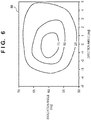
- a plurality of gradation levels may be represented by, for example, different colors in addition to different patterns, or may be represented by contour lines as shown in Fig. 6 .
- a BRDF may be represented by a two-dimensional gradation distribution with changes (gradation) in color or pattern instead of using a plurality of gradation levels.
- the processing unit 15a determines maximum and minimum BRDF values obtained based on the detection result (the intensity distribution of reflected light) obtained by the detection unit (sensor 12f). In this case, the processing unit 15a may normalize the BRDF value, obtained based on the detection result (the intensity distribution of reflected light) obtained by the detection unit (sensor 12f), based on the maximum and minimum BRDF values obtained by using a sample surface for calibration. That is, the obtained BRDF value may be normalized based on the maximum and minimum BRDF values respectively obtained as "10" and "0" using the sample surface for calibration.
- the processing unit 15a then generates a two-dimensional image representing a BRDF as a two-dimensional gradation distribution based on the set values set by the user via the input unit 14.
- the processing unit 15a may generate the two-dimensional image so as to arrange part of the BRDF which corresponds to the specular direction in a central portion of the two-dimensional image.
- the reflection angle ⁇ ' of specular light is determined by the incident angle ⁇ of light with which the measurement surface 20 is irradiated by the irradiation unit of the measurement unit 12. This makes it possible to generate a two-dimensional image so as to arrange part of a BRDF which corresponds to the specular direction in the central portion as long as an irradiation angle range and a direction angle range are set.
- the set values set by the user include “number of gradation levels”, “range of each gradation level”, “irradiation angle range (for example, ⁇ 10°)", and “direction angle range (for example, ⁇ 5°)”.
- the processing unit 15a according to this embodiment generates a two-dimensional image so as to arrange part of the obtained BRDF which corresponds to the specular direction in a central portion of the two-dimensional image.
- this is not exhaustive.
- the processing unit 15a may generate a two-dimensional image so as to arrange the maximum value of the obtained BRDF in a central portion (preferably the center) of the two-dimensional image.
- a measurement system 100 generates a two-dimensional image, as a two-dimensional gradation distribution, representing the BRDF obtained based on the detection result obtained by the detection unit.
- the measurement system 100 then outputs the generated two-dimensional image to the display unit 13a (or the display unit 18f). This allows the user to easily and quickly check the reflection tendency of the measurement surface 20 only by giving one glance at the two-dimensional image.
- this embodiment has exemplified the method of generating a two-dimensional image representing a BRDF as a two-dimensional gradation distribution, an image representing a BRDF as a three-dimensional gradation distribution may be generated by a similar method. It is also possible to generate an image representing the intensity distribution of reflected light detected by the detection unit as a two-dimensional gradation distribution by using a similar method.
- a processing unit 15a outputs, to a display unit 13a (or causes it to display), the one-dimensional gradation distribution obtained by projecting a two-dimensional gradation distribution in a generated two-dimensional image in a direction set in advance (predetermined direction) based on the two-dimensional gradation distribution.
- the two-dimensional gradation distribution is projected by integrating a two-dimensional gradation distribution or extracting representative values.
- the processing unit 15a generates an image representing a one-dimensional distribution in a predetermined direction (to be referred to as a one-dimensional image hereinafter) in the two-dimensional image (the two-dimensional gradation distribution) based on the generated two-dimensional image, and outputs the generated one-dimensional image and two-dimensional image to the display unit 13a.
- the measurement system according to the second embodiment has the same arrangement as that of the measurement system 100 according to the first embodiment, and hence a description of the arrangement will be omitted.
- Fig. 7 is a view showing a two-dimensional image 30 and one-dimensional images 31 and 32.
- the one-dimensional images 31 and 32 each are an image (second image) representing a maximum value distribution in a predetermined direction in a two-dimensional image (two-dimensional gradation distribution) as a gradation distribution.
- the processing unit 15a generates a maximum value distribution with the abscissa axis representing maximum values (representative values) and the ordinate axis representing irradiation angles by obtaining a maximum BRDF value at each irradiation angle in the two-dimensional image 30 (extracting representative values).
- the processing unit 15a can generate the one-dimensional image 31 representing a maximum value distribution corresponding to irradiation angles as a gradation distribution by segmenting (gradation processing) the maximum value distribution according to a plurality of gradation levels used to generate the two-dimensional image 30.
- the processing unit 15a generates a maximum value distribution with the ordinate axis representing maximum values and the abscissa axis representing direction angles by obtaining maximum BRDF values at the respective direction angles in the two-dimensional image 30.
- the processing unit 15a can generate the one-dimensional image 32 representing a maximum value distribution corresponding to direction angles as a gradation distribution by segmenting (gradation processing) the maximum value distribution according to a plurality of gradation levels used to generate the two-dimensional image 30.
- the output unit 13 outputs, to the display unit 13a, the one-dimensional images 31 and 32 generated by the processing unit 15a so as to make the images adjacent to the two-dimensional image 30. Generating one-dimensional images and outputting them to the display unit 13a in this manner allow the user to easily check part of the two-dimensional image 30 which has a high intensity of reflected light and a specific BRDF shape.
- this embodiment has exemplified the method of generating one-dimensional images each representing a maximum value distribution in a predetermined direction in a two-dimensional image as a gradation distribution
- the integral values of a BRDF in a two-dimensional image may be obtained instead of maximum BRDF values in a two-dimensional image.
- the processing unit 15a generates an integral value distribution by obtaining the integral values of a BRDF at the respective irradiation angles (or the respective direction angles) in the two-dimensional image 30 (two-dimensional gradation distribution).
- the processing unit 15a then generates a one-dimensional image representing an integral value distribution corresponding to irradiation angles (or direction angles) as a gradation distribution.
- the processing unit 15a may generate a one-dimensional image representing a BRDF distribution on a line crossing the two-dimensional image 30 (two-dimensional gradation distribution) as a gradation distribution instead of the one-dimensional image representing the maximum value distribution or the integral value distribution as a gradation distribution.
- the processing unit 15a may generate a one-dimensional image representing a BRDF distribution at a predetermined irradiation angle (for example, 60°) as a gradation distribution.
- the output unit 13 outputs the two-dimensional image 30 and the one-dimensional images 31 and 32 to the display unit 13a.
- the output unit 13 may output only the one-dimensional images 31 and 32 to the display unit 13a.
- the third embodiment will exemplify a method of causing an information processing apparatus 18 to process a plurality of measurement results obtained by a plurality of times of measurement by a measurement unit 12.
- Fig. 8 is a view showing an example of a screen (list window 40) of a display unit 18f that displays a list of a plurality of measurement results obtained by a plurality of (five) times of measurement of reflection characteristics.
- a processing unit 18a can include software having a function of causing an output unit 18c to display a list of a plurality of measurement results on the display unit 18f.
- this embodiment will exemplify a method of causing the information processing apparatus 18 to process a plurality of measurement results.
- a similar method can also be applied to a case in which a control unit 15 of a measurement apparatus 10 processes a plurality of measurement results.
- the processing unit 18a acquires a plurality of data obtained by a plurality of times of measurement of reflection characteristics by the measurement unit 12 and stored in a storage unit 15b of the control unit 15 from the control unit 15. The processing unit 18a then causes a storage unit 18b to store the plurality of data acquired from the control unit 15.
- Each data can include a measurement result (index value) on a reflection characteristic of a measurement surface 20 and a two-dimensional image 30 (which may include the one-dimensional images described in the second embodiment) obtained by the control unit 15 (processing unit 15a) of the measurement apparatus 10.
- the processing unit 18a then causes the output unit 18c to display a list of a plurality of measurement results in a region 42 of the list window 40 based on a plurality of data stored in the storage unit 18b.
- the list window 40 shown in Fig. 8 displays indices A, B, and C as measurement results on reflection characteristics of the measurement surface 20.
- Each index value displayed on the list window 40 is any one of a specular gloss, haze, DOI, image clarity, reflectance, and undulation, and can be arbitrarily set by the user.
- the processing unit 18a emphatically displays (for example, displays a selection mark 43) the measurement result selected by the user (No. 1 in Fig. 8 ).
- Fig. 9 is a view showing a screen (detailed window 50) of the display unit 18f on which the two-dimensional image 30 of a BRDF is displayed.
- the detailed window 50 displays the two-dimensional image 30 of a BRDF associated with the measurement result selected by the user in a region 51, and displays the measurement result (the index value of a reflection characteristic) and information about measurement date and time in a region 52.
- the processing unit 18a switches the data (the two-dimensional image of a BRDF and the index value of the reflection characteristic) displayed on the detailed window 50 to another data and displays it.
- the processing unit 18a switches the detailed window 50 to the list window 40 and displays it.
- the list window 40 and the detailed window 50 are respectively displayed in different tabs on the same window, they may be respectively displayed on different windows.
- the present invention can also be implemented by supplying a program for implementing one or more functions of each embodiment described above to a system or apparatus via a network or a storage medium and causing one or more processors in the system or apparatus to read and execute the program.
- the present invention can also be implemented by a circuit implementing one or more functions (for example, ASIC).
Landscapes
- Physics & Mathematics (AREA)
- Health & Medical Sciences (AREA)
- Life Sciences & Earth Sciences (AREA)
- Chemical & Material Sciences (AREA)
- Analytical Chemistry (AREA)
- Biochemistry (AREA)
- General Health & Medical Sciences (AREA)
- General Physics & Mathematics (AREA)
- Immunology (AREA)
- Pathology (AREA)
- Investigating Or Analysing Materials By Optical Means (AREA)
Abstract
Description
- The present invention relates to a measurement apparatus, an information processing apparatus, an information processing method, and a program.
- Surfaces such as printing surfaces, coating surfaces, and the outer surfaces of products are evaluated based on a plurality of types of reflection characteristics (index values) of the surfaces. The plurality of types of reflection characteristics are defined by JIS and ISO standards, and can include specular gloss, haze, DOI (Distinctness of Image), and image clarity.
PTL 1 proposes a measurement apparatus that measures a plurality of types of reflection characteristics like those described above. - PTL 1: Japanese Patent Laid-Open No.
2014-126408 - As a surface reflection characteristic index (indicating a reflection characteristic), a BRDF (Bidirectional Reflectance Distribution Function) is available. A BRDF is an index indicating with what intensity distribution light entering a surface is reflected (the intensity distribution of reflected light), and is useful to evaluate or check a reflection characteristic of light on a measurement surface. Conventionally, however, the BRDF has not been effectively used to evaluate an outer appearance associated with a reflection characteristic of a surface.
- It is therefore an exemplary object of the present invention to provide a measurement apparatus advantageous in evaluating a reflection characteristic of a surface.
- In order to achieve the above object, a measurement apparatus according to one aspect of the present invention is characterized by comprising an irradiation unit configured to obliquely irradiate a surface with light, a detection unit configured to detect an intensity distribution of reflected light from the surface, a processing unit configured to obtain a two-dimensional BRDF of the surface based on the intensity distribution, and a display unit configured to display the BRDF obtained by the processing unit, wherein the detection unit detects the intensity distribution in a direction range that includes a first direction as a direction of specular light from the surface and does not include a direction that defines, together with the first direction, an angle not less than an angle defined by the first direction and a second direction orthogonal to the surface.
- The present invention can provide a measurement apparatus advantageous in evaluating reflection characteristics of a surface.
- Other features and advantages of the present invention will be apparent from the following description made with reference to the accompanying drawings. Note that the same reference numerals denote the same or similar components throughout the accompanying drawings.
- The accompanying drawings, which are incorporated in and constitute a part of the specification, illustrate presently preferred embodiments of the invention, and together with the general description given above and the detailed description of the preferred embodiments given below, serve to explain the principles of the invention.
-
Fig. 1 is a view showing the outer appearance of a measurement system; -
Fig. 2 is a block diagram showing the arrangement of the measurement system; -
Fig. 3 is a view showing the arrangement of a measurement unit; -
Fig. 4 is a view for explaining a BRDF; -
Fig. 5 is a view showing a two-dimensional image; -
Fig. 6 is a view showing a two-dimensional image; -
Fig. 7 is a view showing a two-dimensional image and one-dimensional images; -
Fig. 8 is a view showing a list window; -
Fig. 9 is a view showing a detailed window; and -
Fig. 10 is a view for explaining directions of reflected light. - Preferred embodiments of the present invention will be described below with reference to the accompanying drawings. Note that the same reference numerals denote the same members and elements throughout the drawings, and any redundant description will be omitted.
- The arrangement of a measurement system 100 (measurement apparatus) according to the present invention will be described with reference to
Figs. 1 and2 .Fig. 1 is a view showing an outer appearance of themeasurement system 100.Fig. 2 is a block diagram showing the arrangement of themeasurement system 100. Themeasurement system 100 can include, for example, ameasurement apparatus 10 and an information processing apparatus 18 (computer). Theinformation processing apparatus 18 can include, for example, aprocessing unit 18a (first processing unit) including a CPU, astorage unit 18b including a memory, anoutput unit 18c (second processing unit) that outputs an image, aninput unit 18d including a mouse and a keyboard, and a communication I/F 18e. Theoutput unit 18c has a function as a display control unit that causes adisplay unit 18f such as an LCD to output (display) an image. Theinformation processing apparatus 18 is connected to the measurement apparatus 10 (control unit 15) via the communication I/F 18e wirelessly or using a cable, and can acquire the measurement result (reflection characteristic) obtained by measurement bymeasurement apparatus 10. - The
measurement apparatus 10 can include, for example, ameasurement unit 12, anoutput unit 13, an input unit 14 (operation unit), and thecontrol unit 15, and measures a reflection characteristic of ameasurement surface 20. Themeasurement unit 12 is provided in a housing 11 (inside the housing) and measures a reflection characteristic of themeasurement surface 20 via an opening portion provided in the lower surface of thehousing 11 while outside light is blocked by thehousing 11. Theoutput unit 13 outputs an image onto adisplay unit 13a such as an LCD provided on the upper surface of the housing. That is, theoutput unit 13 can function as a display control unit that causes thedisplay unit 13a to display a reflection characteristic of a measurement surface. Theinput unit 14 receives various settings from a user via a plurality of buttons 14a provided on the upper surface of thehousing 11. Theinput unit 14 according to this embodiment includes the plurality of buttons 14a. However, this is not exhaustive. For example, thedisplay unit 13a (display) provided on the upper surface of thehousing 11 may be of a touch panel type. That is, theinput unit 14 may include the touch paneltype display unit 13a. Thecontrol unit 15 includes aprocessing unit 15a including a CPU and astorage unit 15b including a memory, and controls themeasurement unit 12, theoutput unit 13, and theinput unit 14. In addition, themeasurement apparatus 10 has apower button 16 and a communication I/F 17 (USB port) provided on the housing 11 (its side surface). - The arrangement of the
measurement unit 12 and a method of measuring reflection characteristics (a plurality of types of index values) of themeasurement surface 20 using themeasurement unit 12 will be described next with reference toFig. 3. Fig. 3 is a view showing the arrangement of themeasurement unit 12. Themeasurement unit 12 can include an irradiation unit that obliquely irradiates themeasurement surface 20 with light and a detection unit that detects light (reflected light) reflected by themeasurement surface 20. For example, the irradiation unit includes alight source 12a, alens 12b, aslit 12c, and alens 12d. The detection unit can include alens 12e and asensor 12f. - The light beam emitted from the
light source 12a is collected in theslit 12c by thelens 12b. An image of thelight source 12a is temporarily formed in theslit 12c to become a rectangular secondary light source. A light beam exiting from theslit 12c becomes a divergent light beam again and is collimated by thelens 12d to irradiate themeasurement surface 20. Reflected light from themeasurement surface 20 is formed into a reflection pattern unique to the reflection characteristics of themeasurement surface 20. The light is then collected by thelens 12e and received by the light-receiving surface of thesensor 12f. Thesensor 12f includes an area sensor including a two-dimensional array of photoelectric conversion elements constituted by CCDs or CMOSs. The intensity distribution of reflected light formed on the light-receiving surface of thesensor 12f becomes a reflection pattern whose intensity changes in accordance with an angle as indicated by the inside of the broken line inFig. 3 . In this manner, a plurality of types of index values representing reflection characteristics of themeasurement surface 20 are obtained based on the intensity distribution of reflected light detected by thesensor 12f. - As one of the indices representing reflection characteristics of the
measurement surface 20, a BRDF (Bidirectional Reflectance Distribution Function) is available. One method of obtaining a BRDF based on the intensity distribution of reflected light detected by the detection unit is described in, for example, Japanese Patent Laid-Open No.2016-211999 processing unit 15a) obtains the Fourier transform of a BRDF by dividing the Fourier transform of the intensity distribution of the reflected light detected by the detection unit by the Fourier transform of slit information. The BRDF of themeasurement surface 20 can be obtained by performing the inverse Fourier transform of the obtained Fourier transform. A BRDF is a function representing the distribution of reflectances of a measurement surface, and represents the ratio of the luminance of reflected light to the illuminance of incident light. In a more strict sense, a BRDF at a given point on an object surface is dependent on both incident and reflection directions and defined as the ratio of the intensity of reflected light (diffused light) to the intensity of incident light from an irradiation direction. That is, as shown inFig. 4 , a BRDF is an index indicating with what intensity distribution light entering a given point on a measurement surface is reflected (the intensity distribution of reflected light). - Indices representing reflection characteristics of the
measurement surface 20 include, other than a BRDF, a specular gloss, haze, DOI (Distinctness of Image), image clarity, reflectance, and undulation. Several of these indices will be described. A specular gloss represents the light amount of a specular component. A haze represents the distribution of light around a specular component. A DOI and image clarity indicate a reduction in contrast of a glare image. A specular gloss, haze, DOI, and image clarity can be acquired or generated (calculated) based on an intensity distribution as a blurred image of a rectangular slit instead of a BRDF as a point image distribution function. Accordingly, the control unit 15 (processing unit 15a) can obtain these index values by referring to a table or performing convolution of apparatus information based on the intensity distribution of reflected light detected by the detection unit. - In this case, an incident angle θ (a reflection angle θ' of reflected light from the measurement surface 20) of light with which the
measurement surface 20 is irradiated by the irradiation unit at the time of measurement of reflection characteristics of themeasurement surface 20 is defined for each reflection characteristic index (standard) according to JIS, ISO, or the like. Accordingly, when, for example, a mirror gloss is to be measured as a reflection characteristic index, the incident angle θ is set to any one of 20°, 45°, 60°, 75°, and 85°. In addition, when a haze is to be measured as a reflection characteristic index, the incident angle θ is set to 20° or 30°. When an image clarity is to be measured as a reflection characteristic index, the incident angle θ is set to 45° or 60°. When a DOI is to be measured as a reflection characteristic index, the incident angle θ is set to 20° or 30°. Themeasurement unit 12 may be provided with a plurality of pairs of irradiation units and detection units so as to set different incident angles θ or provided with a driving unit that drives an irradiation unit and a detection unit so as to change the incident angle θ. - The plurality of types of index values (BRDF, mirror gloss, haze, DOI, image clarity, and the like) obtained by the
processing unit 15a in this manner are stored in thestorage unit 15b in association with each other. - The user checks the reflection tendency of light at the
measurement surface 20 by referring to a BRDF indicating with what intensity distribution light entering themeasurement surface 20 is reflected (the intensity distribution of reflected light). At this time, it is preferable in terms of user convenience to display the BRDF so as to allow the user to easily and quickly check the reflection tendency of themeasurement surface 20 only by giving one glance at the display of the BRDF. Accordingly, themeasurement system 100 obtains the two-dimensional BRDF of themeasurement surface 20 based on the intensity distribution of reflected light detected by the measurement unit 12 (detection unit), and displays the obtained two-dimensional BRDF on thedisplay unit 13a (or thedisplay unit 18f). - In this case, the measurement unit 12 (detection unit) detects the intensity distribution of reflected light in the range of predetermined directions, of the directions of reflected light from the
measurement surface 20, which include afirst direction 21 as the direction of specular light from themeasurement surface 20. As shown inFig. 10 , the range of the predetermined directions is the range of directions that do not include adirection 23 defines, with thefirst direction 21, an angle θ2 equal to or more than an angle θ1 defined by thefirst direction 21 and a second direction 22 (normal direction) orthogonal to themeasurement surface 20. That is, the range of the predetermined directions is the range of directions, of the directions of reflected light from themeasurement surface 20, which do not include thedirection 23 defining the angle θ2, with the direction of specular light (first direction 21), which is equal to or more than the angle θ1 (equal to or more than the reflection angle of specular light (θ2 ≥ θ1)). - The range of the predetermined directions corresponds to the range of 0° to 90° as the range of the reflection angles of reflected light from the
measurement surface 20. That is, the range of the predetermined directions is the range of the directions of reflected light with reflection angles larger than 0° and smaller than 90°. In addition, the range of the predetermined directions includes a range on a first plane (an incident plane (for example, the drawing surface)) including specular light and a second plane (for example, a plane orthogonal to the drawing surface) including specular light. That is, the range of predetermined directions is defined on each of the first plane and the second plane. - Specific embodiments will be described below.
- A
processing unit 15a according to this embodiment generates an image (to be referred to as a two-dimensional image hereinafter) representing the BRDF, as a two-dimensional gradation distribution, which is obtained based on the detection result (the intensity distribution of reflected light) obtained by the detection unit in the above manner. Anoutput unit 13 outputs (causes thedisplay unit 13a to display) the two-dimensional image generated by processingunit 15a to adisplay unit 13a. - In this case, the user often wants to check the details of a BRDF near specular light. Accordingly, the
processing unit 15a preferably generates a two-dimensional image such that part of the obtained BRDF which corresponds to a specular direction is arranged in a central portion of the two-dimensional image. At this time, theprocessing unit 15a preferably generates a two-dimensional image in a range in which the reflection angle of reflected light is equal to or more than 0° and equal to or less than 90°. Specular light is reflected light having a reflection angle θ' equal to an incident angle θ of light applied on a measurement surface (that is, the reflection angle θ' of specular light is equal to the incident angle θ). The central portion of a two-dimensional image is a region including the center of the two-dimensional image. - In this embodiment, the
processing unit 15a of ameasurement apparatus 10 generates a two-dimensional image. However, this is not exhaustive, and aprocessing unit 18a of aninformation processing apparatus 18 may generate a two-dimensional image by acquiring the detection result obtained by the detection unit from the a control unit 15 (storage unit 15b). In addition, in the embodiment, theoutput unit 13 of themeasurement apparatus 10 outputs a two-dimensional image to thedisplay unit 13a. However, this is not exhaustive. For example, theoutput unit 13 may output a two-dimensional image to adisplay unit 18f provided outside the measurement apparatus 10 (housing 11) or anoutput unit 18c of theinformation processing apparatus 18 may output a two-dimensional image to thedisplay unit 18f of thedisplay unit 13a. -
Fig. 5 is a view showing a two-dimensional image 30 generated by theprocessing unit 15a and displayed on thedisplay unit 13a by theoutput unit 13. The two-dimensional image 30 shown inFig. 5 represents a BRDF when the incident angle θ of light with which ameasurement surface 20 is irradiated by the irradiation unit of ameasurement unit 12 is set to 60°. The ordinate axis represents irradiation angle, and the abscissa axis represents direction angle. In this case, "irradiation angle" on the ordinate axis of the two-dimensional image 30 shown inFig. 5 represents the reflection angle θ' and is set in the range of 60° ± 10° with reference to 60° that is the reflection angle θ' of reflected light (that is, the incident angle θ on the measurement surface 20). A "direction angle" on the abscissa axis in the two-dimensional image 30 shown inFig. 5 represents an angle difference β (seeFig. 4 ) between specular light and reflected light in a direction orthogonal to a direction in which an irradiation angle (reflection angle θ') is defined and orthogonal to the optical axis of specular light and is set in the range of 0° ± 5°. That is, an "irradiation angle" and a "direction angle" represent angles in two directions each orthogonal to the optical axis of specular light, and a direction in which the irradiation angle is defined is orthogonal to a direction in which the direction angle is defined. Although in this embodiment, the ordinate axis represents "irradiation angle" and the abscissa axis represents "direction angle", the angles represented by the ordinate axis and the abscissa axis may be reversed such that the ordinate axis represents "direction angle" and the abscissa axis represents "irradiation angle". - In the two-
dimensional image 30 shown inFig. 5 , a BRDF is represented as a two-dimensional gradation distribution with a plurality of gradation levels indicating different ranges of BRDF values. A plurality of gradation levels are displayed so as to be identifiable with colors and patterns (patterns such as dots and stripes). More specifically, the two-dimensional image 30 shown inFig. 5 is segmented into four gradation levels with different BRDF value ranges to represent a BRDF as a two-dimensional gradation distribution with four gradation levels with different patterns. In this case, a plurality of gradation levels may be represented by, for example, different colors in addition to different patterns, or may be represented by contour lines as shown inFig. 6 . Alternatively, a BRDF may be represented by a two-dimensional gradation distribution with changes (gradation) in color or pattern instead of using a plurality of gradation levels. - A method of generating a two-dimensional image using the
processing unit 15a will be described next. The following will describe a method of generating a two-dimensional image representing a BRDF as a two-dimensional gradation distribution with a plurality of gradation levels. Theprocessing unit 15a determines maximum and minimum BRDF values obtained based on the detection result (the intensity distribution of reflected light) obtained by the detection unit (sensor 12f). In this case, theprocessing unit 15a may normalize the BRDF value, obtained based on the detection result (the intensity distribution of reflected light) obtained by the detection unit (sensor 12f), based on the maximum and minimum BRDF values obtained by using a sample surface for calibration. That is, the obtained BRDF value may be normalized based on the maximum and minimum BRDF values respectively obtained as "10" and "0" using the sample surface for calibration. - The
processing unit 15a then generates a two-dimensional image representing a BRDF as a two-dimensional gradation distribution based on the set values set by the user via theinput unit 14. In this case, theprocessing unit 15a may generate the two-dimensional image so as to arrange part of the BRDF which corresponds to the specular direction in a central portion of the two-dimensional image. For example, the reflection angle θ' of specular light is determined by the incident angle θ of light with which themeasurement surface 20 is irradiated by the irradiation unit of themeasurement unit 12. This makes it possible to generate a two-dimensional image so as to arrange part of a BRDF which corresponds to the specular direction in the central portion as long as an irradiation angle range and a direction angle range are set. - In this case, the set values set by the user include "number of gradation levels", "range of each gradation level", "irradiation angle range (for example, ±10°)", and "direction angle range (for example, ±5°)". In addition, the
processing unit 15a according to this embodiment generates a two-dimensional image so as to arrange part of the obtained BRDF which corresponds to the specular direction in a central portion of the two-dimensional image. However, this is not exhaustive. For example, theprocessing unit 15a may generate a two-dimensional image so as to arrange the maximum value of the obtained BRDF in a central portion (preferably the center) of the two-dimensional image. - As described above, a
measurement system 100 according to this embodiment generates a two-dimensional image, as a two-dimensional gradation distribution, representing the BRDF obtained based on the detection result obtained by the detection unit. Themeasurement system 100 then outputs the generated two-dimensional image to thedisplay unit 13a (or thedisplay unit 18f). This allows the user to easily and quickly check the reflection tendency of themeasurement surface 20 only by giving one glance at the two-dimensional image. Although this embodiment has exemplified the method of generating a two-dimensional image representing a BRDF as a two-dimensional gradation distribution, an image representing a BRDF as a three-dimensional gradation distribution may be generated by a similar method. It is also possible to generate an image representing the intensity distribution of reflected light detected by the detection unit as a two-dimensional gradation distribution by using a similar method. - In a measurement system according to the second embodiment, a
processing unit 15a outputs, to adisplay unit 13a (or causes it to display), the one-dimensional gradation distribution obtained by projecting a two-dimensional gradation distribution in a generated two-dimensional image in a direction set in advance (predetermined direction) based on the two-dimensional gradation distribution. The two-dimensional gradation distribution is projected by integrating a two-dimensional gradation distribution or extracting representative values. For example, theprocessing unit 15a generates an image representing a one-dimensional distribution in a predetermined direction (to be referred to as a one-dimensional image hereinafter) in the two-dimensional image (the two-dimensional gradation distribution) based on the generated two-dimensional image, and outputs the generated one-dimensional image and two-dimensional image to thedisplay unit 13a. The measurement system according to the second embodiment has the same arrangement as that of themeasurement system 100 according to the first embodiment, and hence a description of the arrangement will be omitted. -
Fig. 7 is a view showing a two-dimensional image 30 and one-dimensional images dimensional images processing unit 15a generates a maximum value distribution with the abscissa axis representing maximum values (representative values) and the ordinate axis representing irradiation angles by obtaining a maximum BRDF value at each irradiation angle in the two-dimensional image 30 (extracting representative values). Theprocessing unit 15a can generate the one-dimensional image 31 representing a maximum value distribution corresponding to irradiation angles as a gradation distribution by segmenting (gradation processing) the maximum value distribution according to a plurality of gradation levels used to generate the two-dimensional image 30. - Likewise, the
processing unit 15a generates a maximum value distribution with the ordinate axis representing maximum values and the abscissa axis representing direction angles by obtaining maximum BRDF values at the respective direction angles in the two-dimensional image 30. Theprocessing unit 15a can generate the one-dimensional image 32 representing a maximum value distribution corresponding to direction angles as a gradation distribution by segmenting (gradation processing) the maximum value distribution according to a plurality of gradation levels used to generate the two-dimensional image 30. Theoutput unit 13 outputs, to thedisplay unit 13a, the one-dimensional images processing unit 15a so as to make the images adjacent to the two-dimensional image 30. Generating one-dimensional images and outputting them to thedisplay unit 13a in this manner allow the user to easily check part of the two-dimensional image 30 which has a high intensity of reflected light and a specific BRDF shape. - Although this embodiment has exemplified the method of generating one-dimensional images each representing a maximum value distribution in a predetermined direction in a two-dimensional image as a gradation distribution, this is not exhaustive. For example, the integral values of a BRDF in a two-dimensional image may be obtained instead of maximum BRDF values in a two-dimensional image. In this case, the
processing unit 15a generates an integral value distribution by obtaining the integral values of a BRDF at the respective irradiation angles (or the respective direction angles) in the two-dimensional image 30 (two-dimensional gradation distribution). Theprocessing unit 15a then generates a one-dimensional image representing an integral value distribution corresponding to irradiation angles (or direction angles) as a gradation distribution. Theprocessing unit 15a may generate a one-dimensional image representing a BRDF distribution on a line crossing the two-dimensional image 30 (two-dimensional gradation distribution) as a gradation distribution instead of the one-dimensional image representing the maximum value distribution or the integral value distribution as a gradation distribution. For example, theprocessing unit 15a may generate a one-dimensional image representing a BRDF distribution at a predetermined irradiation angle (for example, 60°) as a gradation distribution. In addition, in this embodiment, theoutput unit 13 outputs the two-dimensional image 30 and the one-dimensional images display unit 13a. However, theoutput unit 13 may output only the one-dimensional images display unit 13a. - The third embodiment will exemplify a method of causing an
information processing apparatus 18 to process a plurality of measurement results obtained by a plurality of times of measurement by ameasurement unit 12.Fig. 8 is a view showing an example of a screen (list window 40) of adisplay unit 18f that displays a list of a plurality of measurement results obtained by a plurality of (five) times of measurement of reflection characteristics. Aprocessing unit 18a can include software having a function of causing anoutput unit 18c to display a list of a plurality of measurement results on thedisplay unit 18f. In this case, this embodiment will exemplify a method of causing theinformation processing apparatus 18 to process a plurality of measurement results. However, for example, a similar method can also be applied to a case in which acontrol unit 15 of ameasurement apparatus 10 processes a plurality of measurement results. - When the user presses a
data reception button 41 of thelist window 40 via aninput unit 18d, theprocessing unit 18a acquires a plurality of data obtained by a plurality of times of measurement of reflection characteristics by themeasurement unit 12 and stored in astorage unit 15b of thecontrol unit 15 from thecontrol unit 15. Theprocessing unit 18a then causes astorage unit 18b to store the plurality of data acquired from thecontrol unit 15. Each data can include a measurement result (index value) on a reflection characteristic of ameasurement surface 20 and a two-dimensional image 30 (which may include the one-dimensional images described in the second embodiment) obtained by the control unit 15 (processing unit 15a) of themeasurement apparatus 10. - The
processing unit 18a then causes theoutput unit 18c to display a list of a plurality of measurement results in aregion 42 of thelist window 40 based on a plurality of data stored in thestorage unit 18b. In this case, thelist window 40 shown inFig. 8 displays indices A, B, and C as measurement results on reflection characteristics of themeasurement surface 20. Each index value displayed on thelist window 40 is any one of a specular gloss, haze, DOI, image clarity, reflectance, and undulation, and can be arbitrarily set by the user. In addition, when the user selects one measurement result from the list of the plurality of measurement results via theinput unit 18d, theprocessing unit 18a emphatically displays (for example, displays a selection mark 43) the measurement result selected by the user (No. 1 inFig. 8 ). - In this case, when checking the two-
dimensional image 30 of a BRDF concerning the selected measurement result, the user further presses (for example, double-clicks) the measurement result on which theselection mark 43 is displayed via theinput unit 18d. At this time, as shown inFig. 9 , theprocessing unit 18a switches the display tab to display the two-dimensional image 30 (which may include a one-dimensional image) of a BRDF stored in association with the measurement result selected by the user.Fig. 9 is a view showing a screen (detailed window 50) of thedisplay unit 18f on which the two-dimensional image 30 of a BRDF is displayed. Thedetailed window 50 displays the two-dimensional image 30 of a BRDF associated with the measurement result selected by the user in a region 51, and displays the measurement result (the index value of a reflection characteristic) and information about measurement date and time in aregion 52. When the user presses areturn button 53 oradvance button 54 of thedetailed window 50 via theinput unit 18d, theprocessing unit 18a switches the data (the two-dimensional image of a BRDF and the index value of the reflection characteristic) displayed on thedetailed window 50 to another data and displays it. When the user further presses alist tab 55 on the screen, theprocessing unit 18a switches thedetailed window 50 to thelist window 40 and displays it. Although in this embodiment, as shown inFigs. 8 and9 , thelist window 40 and thedetailed window 50 are respectively displayed in different tabs on the same window, they may be respectively displayed on different windows. - The present invention can also be implemented by supplying a program for implementing one or more functions of each embodiment described above to a system or apparatus via a network or a storage medium and causing one or more processors in the system or apparatus to read and execute the program. The present invention can also be implemented by a circuit implementing one or more functions (for example, ASIC).
- The present invention is not limited to the above-described embodiments, and various changes and modifications can be made within the spirit and scope of the present invention. Therefore, to apprise the public of the scope of the present invention, the following claims are made.
- This application claims the priority on the basis of Japanese Patent Application No.
2017-004614, filed January 13, 2017
Claims (20)
- A measurement apparatus characterized by comprising:an irradiation unit configured to obliquely irradiate a surface with light;a detection unit configured to detect an intensity distribution of reflected light from the surface;a processing unit configured to obtain a two-dimensional BRDF of the surface based on the intensity distribution; anda display unit configured to display the BRDF obtained by the processing unit,wherein the detection unit detects the intensity distribution in a direction range that includes a first direction as a direction of specular light from the surface and does not include a direction that defines, together with the first direction, an angle not less than an angle defined by the first direction and a second direction orthogonal to the surface.
- The measurement apparatus according to claim 1, characterized in that the range corresponds, as a range of reflection angles of the reflected light, to a range not less than 0° and not more than 90°.
- The measurement apparatus according to claim 1 or 2, characterized in that the range is a range on each of an incident plane including the specular light and a plane including the specular light and orthogonal to the incident plane.
- The measurement apparatus according to any one of claims 1 to 3, characterized in that the processing unit causes the display unit to display the BRDF as a two-dimensional gradation distribution.
- The measurement apparatus according to claim 4, characterized in that the processing unit causes the display unit to display a one-dimensional gradation distribution obtained by projecting the gradation distribution in a predetermined direction.
- The measurement apparatus according to claim 5, characterized in that the processing unit performs the projection by integrating the two-dimensional gradation distribution or extracting representative values.
- The measurement apparatus according to claim 5 or 6, characterized in that the processing unit causes the display unit to display a one-dimensional gradation distribution as a gradation distribution on a line crossing the two-dimensional gradation distribution.
- The measurement apparatus according to any one of claims 4 to 7, characterized in that the processing unit causes the display unit to display the gradation distribution with a change in color.
- The measurement apparatus according to any one of claims 4 to 7, characterized in that the processing unit causes the display unit to display the gradation distribution with a change in pattern.
- The measurement apparatus according to any one of claims 1 to 9, characterized in that the processing unit obtains at least one of a mirror gloss, a haze, a DOI, an image clarity, a reflectance, and an undulation of the surface based on the intensity distribution, and cause the display unit to display the at least one.
- The measurement apparatus according to any one of claims 1 to 10, characterized by further comprising a housing provided with the irradiation unit and the detection unit,
wherein the display unit is provided outside the housing. - An information processing apparatus that processes information of an intensity distribution of reflected light from a surface which is obtained by obliquely irradiating the surface with light, characterized by comprising:a first processing unit configured to obtain a two-dimensional BRDF of the surface based on the information; anda second processing unit configured to cause a display unit to display the BRDF as a two-dimensional gradation distribution,wherein the intensity distribution is obtained in a direction range that includes a first direction as a direction of specular light from the surface and does not include a direction that defines, together with the first direction, an angle not less than an angle defined by the first direction and a second direction orthogonal to the surface.
- An information processing method of processing information of an intensity distribution of reflected light from a surface which is obtained by obliquely irradiating the surface with light, characterized by comprising:a first step of obtaining a two-dimensional BRDF of the surface based on the information; anda second step of causing a display unit to display the BRDF as a two-dimensional gradation distribution,wherein the intensity distribution is obtained in a direction range that includes a first direction as a direction of specular light from the surface and does not include a direction that defines, together with the first direction, an angle not less than an angle defined by the first direction and a second direction orthogonal to the surface.
- A program for causing a computer to execute each step in an information processing method defined in claim 13.
- A measurement apparatus characterized by comprising:an irradiation unit configured to obliquely irradiate a surface with light;a detection unit configured to detect an intensity distribution of reflected light from the surface;a processing unit configured to obtain a two-dimensional BRDF of the surface based on the intensity distribution and obtain a one-dimensional gradation distribution by projecting the two-dimensional BRDF in a predetermined direction; anda display unit configured to display the one-dimensional gradation distribution obtained by the processing unit.
- The measurement apparatus according to claim 15, characterized in that the processing unit performs the projection by integrating the two-dimensional BRDF or extracting representative values.
- The measurement apparatus according to claim 15 or 16, characterized in that the processing unit causes the display unit to display a one-dimensional gradation distribution as a gradation distribution on a line crossing the two-dimensional BRDF.
- An information processing apparatus that processes information of an intensity distribution of reflected light from a surface which is obtained by obliquely irradiating the surface with light, characterized by comprising:a first processing unit configured to obtain a two-dimensional BRDF of the surface based on the information; anda second processing unit configured to cause a display unit to display a one-dimensional gradation distribution obtained by projecting the two-dimensional BRDF in a predetermined direction.
- An information processing method of processing information of an intensity distribution of reflected light from a surface which is obtained by obliquely irradiating the surface with light, characterized by comprising:a first step of obtaining a two-dimensional BRDF of the surface based on the information; anda second step of causing a display unit to display a one-dimensional gradation distribution obtained by projecting the two-dimensional BRDF in a predetermined direction.
- A program for causing a computer to execute a step in an information processing method defined in claim 19.
Applications Claiming Priority (2)
| Application Number | Priority Date | Filing Date | Title |
|---|---|---|---|
| JP2017004614A JP6557688B2 (en) | 2017-01-13 | 2017-01-13 | Measuring device, information processing device, information processing method, and program |
| PCT/JP2017/042952 WO2018131308A1 (en) | 2017-01-13 | 2017-11-30 | Measuring device, information processing device, information processing method, and program |
Publications (2)
| Publication Number | Publication Date |
|---|---|
| EP3570010A1 true EP3570010A1 (en) | 2019-11-20 |
| EP3570010A4 EP3570010A4 (en) | 2020-10-07 |
Family
ID=62839949
Family Applications (1)
| Application Number | Title | Priority Date | Filing Date |
|---|---|---|---|
| EP17891867.8A Withdrawn EP3570010A4 (en) | 2017-01-13 | 2017-11-30 | Measuring device, information processing device, information processing method, and program |
Country Status (5)
| Country | Link |
|---|---|
| US (1) | US20190331600A1 (en) |
| EP (1) | EP3570010A4 (en) |
| JP (1) | JP6557688B2 (en) |
| CN (1) | CN110192099A (en) |
| WO (1) | WO2018131308A1 (en) |
Families Citing this family (2)
| Publication number | Priority date | Publication date | Assignee | Title |
|---|---|---|---|---|
| CN114609094A (en) * | 2022-04-01 | 2022-06-10 | 陕西科技大学 | BRDF measurement method of inner surface based on brightness of endoscopic image and normal distribution of inner surface of hole |
| CN116402819B (en) * | 2023-06-08 | 2023-09-12 | 季华实验室 | Mirror-like defect detection method, device, electronic equipment and storage medium |
Family Cites Families (19)
| Publication number | Priority date | Publication date | Assignee | Title |
|---|---|---|---|---|
| JPS62197718A (en) * | 1986-02-25 | 1987-09-01 | Agency Of Ind Science & Technol | Measuring for light beam pattern |
| JPH0687194B2 (en) * | 1986-05-13 | 1994-11-02 | 日本電子株式会社 | How to display time series temperature distribution image data |
| US5313542A (en) * | 1992-11-30 | 1994-05-17 | Breault Research Organization, Inc. | Apparatus and method of rapidly measuring hemispherical scattered or radiated light |
| DE19954183C2 (en) * | 1999-11-08 | 2003-07-31 | Autronic Melchers Gmbh | Method and device for measuring and evaluating the scattering behavior of surfaces |
| JP4745512B2 (en) * | 2001-02-09 | 2011-08-10 | キヤノン株式会社 | Color image forming apparatus |
| ATE414270T1 (en) * | 2004-10-08 | 2008-11-15 | Koninkl Philips Electronics Nv | OPTICAL INSPECTION OF TEST SURFACES |
| CN100494986C (en) * | 2004-10-29 | 2009-06-03 | 夏普株式会社 | Specular gloss predication device, specular gloss predication method, control program for specular gloss predication device and medium |
| WO2006116386A1 (en) * | 2005-04-25 | 2006-11-02 | X-Rite, Incorporated | Measuring an appearance property of a surface using a spatially under-sampled bidirectional reflectance distribution function |
| US7668342B2 (en) * | 2005-09-09 | 2010-02-23 | Carl Zeiss Meditec, Inc. | Method of bioimage data processing for revealing more meaningful anatomic features of diseased tissues |
| JP2008256454A (en) * | 2007-04-03 | 2008-10-23 | Konica Minolta Sensing Inc | Optical characteristic measuring device and method |
| JP2010537188A (en) * | 2007-08-22 | 2010-12-02 | コーニンクレッカ フィリップス エレクトロニクス エヌ ヴィ | Method and apparatus for optical characterization of surfaces |
| JP5315025B2 (en) * | 2007-11-30 | 2013-10-16 | 株式会社日立ハイテクノロジーズ | Spectral analysis and display |
| US8374831B2 (en) * | 2009-04-24 | 2013-02-12 | E I Du Pont De Nemours And Company | Process for generating bidirectional reflectance distribution functions of gonioapparent materials with limited measurement data |
| FR2986337B1 (en) * | 2012-01-31 | 2014-09-05 | Jean-Pierre Lauret | OPTICAL SYSTEM FOR MEASURING BRDF, BSDF AND BDTF |
| JP6053506B2 (en) * | 2012-12-25 | 2016-12-27 | キヤノン株式会社 | Reflection characteristic measuring device |
| JP6410451B2 (en) * | 2014-03-31 | 2018-10-24 | キヤノン株式会社 | Information processing apparatus, measurement system, information processing method, and program. |
| JP6635674B2 (en) | 2015-05-11 | 2020-01-29 | キヤノン株式会社 | Measuring device, measuring method and program |
| JP6560028B2 (en) | 2015-06-04 | 2019-08-14 | 株式会社日本触媒 | Electrode for air metal battery and air metal battery |
| JP6614827B2 (en) * | 2015-06-30 | 2019-12-04 | キヤノン株式会社 | Length measuring device and article manufacturing method |
-
2017
- 2017-01-13 JP JP2017004614A patent/JP6557688B2/en active Active
- 2017-11-30 CN CN201780082738.9A patent/CN110192099A/en active Pending
- 2017-11-30 WO PCT/JP2017/042952 patent/WO2018131308A1/en not_active Ceased
- 2017-11-30 EP EP17891867.8A patent/EP3570010A4/en not_active Withdrawn
-
2019
- 2019-07-09 US US16/506,197 patent/US20190331600A1/en not_active Abandoned
Also Published As
| Publication number | Publication date |
|---|---|
| JP2018112532A (en) | 2018-07-19 |
| CN110192099A (en) | 2019-08-30 |
| WO2018131308A1 (en) | 2018-07-19 |
| US20190331600A1 (en) | 2019-10-31 |
| EP3570010A4 (en) | 2020-10-07 |
| JP6557688B2 (en) | 2019-08-07 |
Similar Documents
| Publication | Publication Date | Title |
|---|---|---|
| JP6053506B2 (en) | Reflection characteristic measuring device | |
| CA2699695C (en) | Detecting ambient light levels in a vision system | |
| JP7027807B2 (en) | Display devices, scanners, display systems and programs | |
| EP3220101B1 (en) | Texture evaluation apparatus, texture evaluation method, and computer-readable recording medium | |
| US10837903B2 (en) | Information processing apparatus, method of deriving reflection characteristics, program, and reflection characteristic profile | |
| EP3557216A1 (en) | Inspection device, inspection method, and program | |
| JP6542906B2 (en) | Method and apparatus for determining surface data and / or measurement data associated with the surface of an at least partially transparent object | |
| CN105277558A (en) | Multiple-stage method of investigating surfaces and corresponding apparatus | |
| US20190128806A1 (en) | Reflection characteristic measurement apparatus, machining system, reflection characteristic measurement method, object machining method, and non-transitory computer-readable storage medium | |
| EP3570010A1 (en) | Measuring device, information processing device, information processing method, and program | |
| US20170345168A1 (en) | Image processing apparatus, image processing method, and storage medium | |
| EP3605467B1 (en) | Coating color identifying device, coating color identifying method, coating color identifying program, and computer-readable medium containing coating color identifying program | |
| EP3570011A1 (en) | Measuring device, information processing device, information processing method, and program | |
| US20200408684A1 (en) | Measurement device, measurement method, and non-transitory storage medium | |
| EP3240993B1 (en) | An arrangement of optical measurement | |
| JP2000019064A (en) | Film evaluation method and film evaluation device | |
| KR102599207B1 (en) | Apparatus and method for measuring surface of electronic device | |
| CN114729879A (en) | Optical property measurement using sensor behind display screen | |
| JP2017190957A (en) | Optical measuring device | |
| JP2026000681A (en) | Processing device for optical device, optical device, optical object information acquisition method, and optical object information acquisition program | |
| JP7367562B2 (en) | Gloss evaluation device and method | |
| JP2018112533A (en) | Measuring device, information processing device, information processing method, and program | |
| KR100809553B1 (en) | Apparatus and method for evaluating color image sensors | |
| Inoue et al. | Line Spread Function of Specular Reflection and Gloss Unevenness Analysis | |
| EP3575777A1 (en) | Apparatus for determining the bi-directional distribution function using an asymmetric illumination pattern |
Legal Events
| Date | Code | Title | Description |
|---|---|---|---|
| STAA | Information on the status of an ep patent application or granted ep patent |
Free format text: STATUS: THE INTERNATIONAL PUBLICATION HAS BEEN MADE |
|
| PUAI | Public reference made under article 153(3) epc to a published international application that has entered the european phase |
Free format text: ORIGINAL CODE: 0009012 |
|
| STAA | Information on the status of an ep patent application or granted ep patent |
Free format text: STATUS: REQUEST FOR EXAMINATION WAS MADE |
|
| 17P | Request for examination filed |
Effective date: 20190813 |
|
| AK | Designated contracting states |
Kind code of ref document: A1 Designated state(s): AL AT BE BG CH CY CZ DE DK EE ES FI FR GB GR HR HU IE IS IT LI LT LU LV MC MK MT NL NO PL PT RO RS SE SI SK SM TR |
|
| AX | Request for extension of the european patent |
Extension state: BA ME |
|
| DAV | Request for validation of the european patent (deleted) | ||
| DAX | Request for extension of the european patent (deleted) | ||
| A4 | Supplementary search report drawn up and despatched |
Effective date: 20200908 |
|
| RIC1 | Information provided on ipc code assigned before grant |
Ipc: G01N 21/57 20060101ALI20200902BHEP Ipc: G01N 21/55 20140101AFI20200902BHEP |
|
| STAA | Information on the status of an ep patent application or granted ep patent |
Free format text: STATUS: THE APPLICATION HAS BEEN WITHDRAWN |
|
| 18W | Application withdrawn |
Effective date: 20210722 |