EP3570007A1 - Humidity sensor and corrosion test method using the same - Google Patents
Humidity sensor and corrosion test method using the same Download PDFInfo
- Publication number
- EP3570007A1 EP3570007A1 EP19173250.2A EP19173250A EP3570007A1 EP 3570007 A1 EP3570007 A1 EP 3570007A1 EP 19173250 A EP19173250 A EP 19173250A EP 3570007 A1 EP3570007 A1 EP 3570007A1
- Authority
- EP
- European Patent Office
- Prior art keywords
- sensor
- coating
- humidity sensor
- conductive materials
- humidity
- Prior art date
- Legal status (The legal status is an assumption and is not a legal conclusion. Google has not performed a legal analysis and makes no representation as to the accuracy of the status listed.)
- Withdrawn
Links
- 230000007797 corrosion Effects 0.000 title claims description 43
- 238000005260 corrosion Methods 0.000 title claims description 43
- 238000010998 test method Methods 0.000 title claims description 9
- 239000004020 conductor Substances 0.000 claims abstract description 62
- 239000011248 coating agent Substances 0.000 claims abstract description 56
- 238000000576 coating method Methods 0.000 claims abstract description 56
- 239000011810 insulating material Substances 0.000 claims abstract description 31
- 229920005989 resin Polymers 0.000 claims description 10
- 239000011347 resin Substances 0.000 claims description 10
- 238000000034 method Methods 0.000 claims description 6
- 230000002093 peripheral effect Effects 0.000 claims description 5
- 230000007613 environmental effect Effects 0.000 claims description 3
- XEEYBQQBJWHFJM-UHFFFAOYSA-N iron Substances [Fe] XEEYBQQBJWHFJM-UHFFFAOYSA-N 0.000 description 47
- 230000035945 sensitivity Effects 0.000 description 12
- XLYOFNOQVPJJNP-UHFFFAOYSA-N water Substances O XLYOFNOQVPJJNP-UHFFFAOYSA-N 0.000 description 12
- 238000001514 detection method Methods 0.000 description 9
- 239000010408 film Substances 0.000 description 9
- WABPQHHGFIMREM-UHFFFAOYSA-N lead(0) Chemical compound [Pb] WABPQHHGFIMREM-UHFFFAOYSA-N 0.000 description 8
- 150000003839 salts Chemical class 0.000 description 8
- 239000000463 material Substances 0.000 description 7
- 239000000758 substrate Substances 0.000 description 6
- 229910052751 metal Inorganic materials 0.000 description 5
- 239000002184 metal Substances 0.000 description 5
- 238000012360 testing method Methods 0.000 description 5
- 230000000052 comparative effect Effects 0.000 description 4
- 230000000875 corresponding effect Effects 0.000 description 4
- 238000013461 design Methods 0.000 description 4
- 238000011156 evaluation Methods 0.000 description 4
- 238000004804 winding Methods 0.000 description 4
- 230000006866 deterioration Effects 0.000 description 3
- 239000011888 foil Substances 0.000 description 3
- 230000007423 decrease Effects 0.000 description 2
- 238000003745 diagnosis Methods 0.000 description 2
- 239000012212 insulator Substances 0.000 description 2
- 239000007769 metal material Substances 0.000 description 2
- 229910052697 platinum Inorganic materials 0.000 description 2
- 229910052709 silver Inorganic materials 0.000 description 2
- 239000004593 Epoxy Substances 0.000 description 1
- 229910001335 Galvanized steel Inorganic materials 0.000 description 1
- CERQOIWHTDAKMF-UHFFFAOYSA-N Methacrylic acid Chemical compound CC(=C)C(O)=O CERQOIWHTDAKMF-UHFFFAOYSA-N 0.000 description 1
- 239000004698 Polyethylene Substances 0.000 description 1
- 239000004642 Polyimide Substances 0.000 description 1
- 206010042928 Syringomyelia Diseases 0.000 description 1
- 229910052782 aluminium Inorganic materials 0.000 description 1
- 230000015556 catabolic process Effects 0.000 description 1
- 238000009833 condensation Methods 0.000 description 1
- 230000005494 condensation Effects 0.000 description 1
- 229920001940 conductive polymer Polymers 0.000 description 1
- 229910052802 copper Inorganic materials 0.000 description 1
- 230000002596 correlated effect Effects 0.000 description 1
- 238000011161 development Methods 0.000 description 1
- 230000018109 developmental process Effects 0.000 description 1
- 238000005868 electrolysis reaction Methods 0.000 description 1
- 239000003822 epoxy resin Substances 0.000 description 1
- 239000008397 galvanized steel Substances 0.000 description 1
- 230000012447 hatching Effects 0.000 description 1
- 238000009413 insulation Methods 0.000 description 1
- 229910052742 iron Inorganic materials 0.000 description 1
- 238000004519 manufacturing process Methods 0.000 description 1
- 238000005259 measurement Methods 0.000 description 1
- 238000012544 monitoring process Methods 0.000 description 1
- 229910052759 nickel Inorganic materials 0.000 description 1
- 229910000510 noble metal Inorganic materials 0.000 description 1
- 230000003647 oxidation Effects 0.000 description 1
- 238000007254 oxidation reaction Methods 0.000 description 1
- 238000010422 painting Methods 0.000 description 1
- 238000005498 polishing Methods 0.000 description 1
- 229920000647 polyepoxide Polymers 0.000 description 1
- 229920000728 polyester Polymers 0.000 description 1
- 229920001225 polyester resin Polymers 0.000 description 1
- 239000004645 polyester resin Substances 0.000 description 1
- -1 polyethylene Polymers 0.000 description 1
- 229920000573 polyethylene Polymers 0.000 description 1
- 229920001721 polyimide Polymers 0.000 description 1
- 239000002861 polymer material Substances 0.000 description 1
- 239000010409 thin film Substances 0.000 description 1
Images



Classifications
-
- G—PHYSICS
- G01—MEASURING; TESTING
- G01N—INVESTIGATING OR ANALYSING MATERIALS BY DETERMINING THEIR CHEMICAL OR PHYSICAL PROPERTIES
- G01N17/00—Investigating resistance of materials to the weather, to corrosion, or to light
- G01N17/02—Electrochemical measuring systems for weathering, corrosion or corrosion-protection measurement
-
- G—PHYSICS
- G01—MEASURING; TESTING
- G01N—INVESTIGATING OR ANALYSING MATERIALS BY DETERMINING THEIR CHEMICAL OR PHYSICAL PROPERTIES
- G01N17/00—Investigating resistance of materials to the weather, to corrosion, or to light
- G01N17/04—Corrosion probes
-
- G—PHYSICS
- G01—MEASURING; TESTING
- G01N—INVESTIGATING OR ANALYSING MATERIALS BY DETERMINING THEIR CHEMICAL OR PHYSICAL PROPERTIES
- G01N27/00—Investigating or analysing materials by the use of electric, electrochemical, or magnetic means
- G01N27/02—Investigating or analysing materials by the use of electric, electrochemical, or magnetic means by investigating impedance
- G01N27/04—Investigating or analysing materials by the use of electric, electrochemical, or magnetic means by investigating impedance by investigating resistance
- G01N27/048—Investigating or analysing materials by the use of electric, electrochemical, or magnetic means by investigating impedance by investigating resistance for determining moisture content of the material
-
- G—PHYSICS
- G01—MEASURING; TESTING
- G01N—INVESTIGATING OR ANALYSING MATERIALS BY DETERMINING THEIR CHEMICAL OR PHYSICAL PROPERTIES
- G01N27/00—Investigating or analysing materials by the use of electric, electrochemical, or magnetic means
- G01N27/02—Investigating or analysing materials by the use of electric, electrochemical, or magnetic means by investigating impedance
- G01N27/04—Investigating or analysing materials by the use of electric, electrochemical, or magnetic means by investigating impedance by investigating resistance
- G01N27/12—Investigating or analysing materials by the use of electric, electrochemical, or magnetic means by investigating impedance by investigating resistance of a solid body in dependence upon absorption of a fluid; of a solid body in dependence upon reaction with a fluid, for detecting components in the fluid
- G01N27/121—Investigating or analysing materials by the use of electric, electrochemical, or magnetic means by investigating impedance by investigating resistance of a solid body in dependence upon absorption of a fluid; of a solid body in dependence upon reaction with a fluid, for detecting components in the fluid for determining moisture content, e.g. humidity, of the fluid
-
- G—PHYSICS
- G01—MEASURING; TESTING
- G01N—INVESTIGATING OR ANALYSING MATERIALS BY DETERMINING THEIR CHEMICAL OR PHYSICAL PROPERTIES
- G01N27/00—Investigating or analysing materials by the use of electric, electrochemical, or magnetic means
- G01N27/26—Investigating or analysing materials by the use of electric, electrochemical, or magnetic means by investigating electrochemical variables; by using electrolysis or electrophoresis
- G01N27/28—Electrolytic cell components
- G01N27/30—Electrodes, e.g. test electrodes; Half-cells
Definitions
- the present disclosure relates to a humidity sensor and a corrosion test method using the same.
- An atmospheric corrosion monitoring (ACM) sensor has been known as a sensor used for a corrosion test.
- This sensor is made of insulating paste which is screen-printed on a target metal (e.g., a Fe plate, or a galvanized steel plate) serving as a substrate, and conductive paste (e.g., Ag) printed on the insulating paste while keeping insulation from the substrate.
- a target metal e.g., a Fe plate, or a galvanized steel plate
- conductive paste e.g., Ag
- Japanese Unexamined Patent Publication No. 2010-133748 describes another example of the corrosion test method.
- This method uses a corrosion sensor including a plurality of conductive portions provided on a surface of a substrate via a plurality of insulators.
- the substrate of the corrosion sensor is made of the same material as that of components of a structure exposed to the atmosphere, and has its surface covered with the same coating as that applied to the components.
- rainwater enters through the crack to cause a short circuit between the conductive portions and the substrate, and a corrosion current flows.
- this current is measured with an ammeter, the degree of deterioration of the coating can be determined.
- the ACM sensor is used to monitor the degree of corrosiveness of the environment around the target metal exposed to the atmosphere. Specifically, the sensor is used in an uncoated state. While corrosion proceeds under the coating, the environment under the coating and the environment outside the coating do not necessarily have the same degree of corrosiveness. That is, the ACM sensor cannot evaluate the degree of corrosiveness under the coating.
- a corrosion current is detected with the surface of the sensor covered with a coating.
- no corrosion current flows unless a crack is caused in the coating and rainwater enters through the crack.
- a product covered with a coating repeatedly experiences a phenomenon in which a corrosion factor penetrates the coating to reach the product surface under the coating or the corrosion factor under the coating goes outside the coating.
- the corrosion test method disclosed in Japanese Unexamined Patent Publication No. 2010-133748 cannot monitor such coming and going of the corrosion factor.
- the surface of the sensor has irregularities due to the stacking of the conductive portions on the insulators, which makes it difficult to form the coating of a uniform thickness. Thus, it is not easy to evaluate the influence of the thickness of the coating on the corrosion resistance.
- conductive materials are alternately stacked with an electrical insulating material interposed therebetween, and an outcrop of the stack is used as a sensor surface to detect humidity and a corrosion factor.
- the humidity sensor disclosed herein includes: a sensor body including a first conductive material and a second conductive material which are alternately stacked with an insulating material interposed therebetween; and lead wires respectively connected to the first and second conductive materials to connect the first and second conductive materials to a power supply and an ammeter, wherein the sensor body has an outcrop in which a layer of the first conductive material and a layer of the second conductive material are alternately exposed with a layer of the insulating material interposed therebetween, the outcrop serving as a sensor surface, and the power supply applies a voltage between the first and second conductive materials so that humidity is detected based on a current which flows when a short circuit is caused between the first and second conductive materials by humidity on the sensor surface.
- the outcrop of this humidity sensor in which the layers of the first conductive material, the second conductive material, and the insulating material are exposed is used as the sensor surface.
- the humidity detection sensitivity corresponds to the interval between the first and second conductive materials (thickness of the insulating material)
- the detection can be achieved with high sensitivity (the sensitivity increases with the decrease in the interval between the first and second conductive materials).
- the detection sensitivity decreases due to the deterioration of the sensor surface (e.g., oxidation of an exposed portion of the conductive materials)
- the sensor surface is polished so that the exposed edges of the first and second conductive materials are renewed. This can recover the detection sensitivity.
- first and second conductive materials examples include a metal material, an inorganic conductive material, and a conductive polymer material.
- the first and second conductive materials may be the same material or different materials.
- Preferred examples of the metal material include Fe, Al, Ag, Cu, Ni, and Pt. In terms of high durability, noble metals such as Ag and Pt are preferred.
- the insulating material examples include a resin such as polyester, polyimide, polyethylene, and epoxy.
- the first and second conductive materials are wound in a spiral fashion with the insulating material interposed therebetween to form the sensor body. Winding the conductive materials in this way makes it possible to obtain a stack in which the first and second conductive materials are alternately stacked with the insulating material interposed therebetween.
- the sensor body is not limited to the wound body, and may be a simply stacked body in which a plurality of films of the first conductive material and a plurality of films of the second conductive material are alternately stacked with the insulating material interposed therebetween.
- the sensor body may include a film of the insulating material folded in a zigzag shape, and the plurality of films of the first conductive material and the plurality of films of the second conductive material may be alternately inserted between the folds of the insulating material film.
- each of the first and second conductive materials is continuous.
- each lead wire is just connected to the first or second conductive material at a single point, so that the configuration is simplified.
- both of the conductive materials and the insulating material can be made thin, which can advantageously improve the detection sensitivity.
- the sensor surface has irregularities of less than 1 ⁇ m.
- a uniform coating can be formed on the sensor surface of the humidity sensor with high accuracy and less limitations on the kinds of the coating material. This is advantageous in obtaining a highly reliable result of a corrosion test.
- the insulating material has a thickness of not less than 1 ⁇ m and not more than 100 ⁇ m. Setting the thickness not more than 100 ⁇ m makes it possible to achieve high detection sensitivity, and is advantageous in view of ease of the winding of the components of the sensor body. Further, since the thickness is not less than 1 ⁇ m, the wound sensor body, the simply stacked sensor body, or the folded sensor body can be easily obtained without impairing the electrical insulating property.
- the thickness of the insulating material is not less than 10 ⁇ m and not more than 80 ⁇ m. In a more preferred embodiment, the thickness is not less than 20 ⁇ m and not more than 50 ⁇ m.
- each of the first and second conductive materials has a thickness of not less than 1 ⁇ m and not more than 100 ⁇ m. Setting the thickness not more than 100 ⁇ m makes it possible to achieve high detection sensitivity, and is advantageous in view of ease of the winding of the components of the sensor body. Further, since the thickness is not less than 1 ⁇ m, the wound sensor body, the simply stacked sensor body, or the folded sensor body can be easily obtained. In a preferred embodiment, the thickness of each of the conductive materials is not less than 10 ⁇ m and not more than 80 ⁇ m. In a more preferred embodiment, the thickness is not less than 20 ⁇ m and not more than 50 ⁇ m.
- the first and second conductive materials are alternately arranged at a pitch of not more than 200 ⁇ m, and the interval between the first and second conductive materials is not more than 100 ⁇ m.
- the pitch is not less than 20 ⁇ m and not more than 160 ⁇ m, and the interval is not less than 10 ⁇ m and not more than 80 ⁇ m.
- the pitch is not less than 40 ⁇ m and not more than 100 ⁇ m, and the interval is not less than 20 ⁇ m and not more than 50 ⁇ m.
- an embedding resin layer is provided on a peripheral surface of the sensor body. This can reliably maintain the conductive materials and the insulating material in the stacked state, and can advantageously stabilize the quality.
- the embedding resin include an epoxy resin, a methacrylic acid resin, and a polyester resin.
- a corrosion resistance test method disclosed herein uses the above-described humidity sensor as a corrosion sensor.
- the method includes: forming a coating on the sensor surface of the humidity sensor; connecting the lead wires of the humidity sensor to a power supply and an ammeter; and measuring, in a corrosive environment, a current generated as a result of a short circuit caused between the first and second conductive materials exposed on the sensor surface by a corrosion factor that has penetrated the coating.
- the current flows as a result of a short circuit caused between the first and second conductive materials by a corrosion factor such as water that has penetrated the coating and reached the sensor surface. Therefore, whether the current is detected or not and the change in the current value with time can be used as evaluation indices of the degree of corrosiveness of the environment under the coating.
- the layer of the first conductive material and the layer of the second conductive material are alternately exposed on the sensor surface with the layer of the insulating material interposed therebetween. This makes it possible to detect the coming and going of the corrosion factor with high sensitivity. This can advantageously improve the reliability of the evaluation of the degree of the corrosiveness of the environment under the coating and the diagnosis of aged deterioration of the coating, and by extension, can advantageously contribute to the development of a new material of the coating based on the results of the evaluation and the diagnosis.
- the humidity sensor After use of the humidity sensor as a corrosion sensor, the coating on the sensor surface is removed by polishing so that the exposed edges of the first and second conductive materials are renewed. Thus, the humidity sensor can be reused as the corrosion sensor.
- the sensor surface has irregularities of less than 1 ⁇ m. This makes it possible to form a uniform coating by, for example, painting, on the sensor surface with high accuracy and less limitations on the kinds of the coating material. This is advantageous in obtaining a highly reliable result of a corrosion test on, e.g., the influence of the coating thickness on the corrosion resistance.
- the voltage applied between the first and second conductive materials is not less than 0.1 V and not more than 20 V. Setting the applied voltage too low is disadvantageous for detecting the current generated by the short circuit. On the other hand, setting the applied voltage high brings about electrolysis of water that has reached under the coating or dielectric breakdown of the coating, which may lead to detection failure of the current generated by the short circuit.
- the applied voltage is not less than 0.5 V and not more than 10 V. In a more preferred embodiment, the applied voltage is not less than 1 V and not more than 3 V.
- the coating is identical to a coating applied to parts of an automobile.
- the humidity sensor is arranged on some of the parts of the automobile and covered with a coating covering the some of the parts, and data of the current that changes with time due to an environmental change accompanying travel of the automobile is acquired.
- a humidity sensor 1 shown in FIG. 1 includes a sensor body 2, from which lead wires 4 and 5 extend to connect the sensor body 2 to a power supply 8 and an ammeter 3.
- the sensor body 2 has a cylindrical shape, and one end surface thereof serves as a sensor surface 6.
- a peripheral surface of the sensor body 2 orthogonal to the sensor surface 6, and the other end surface of the sensor body 2 are covered with an embedding resin layer 7.
- the sensor body 2 of this embodiment includes metal foil of the same kind, namely, iron foil 11, 12, as a first conductive material and a second conductive material.
- First iron foil 11 as a first conductive material and second iron foil 12 as a second conductive material are wound in a spiral fashion with an insulating layer (resin) 13 interposed therebetween. Winding these materials in this manner forms the sensor body 2 in which the first iron foil 11 and the second iron foil 12 are alternately stacked with the insulating layer interposed therebetween.
- An outcrop of the sensor body 2 in which layers (edges) of the first iron foil 11, the second iron foil 12, and the insulating layer 13 are exposed serves as the sensor surface 6.
- the hatching is merely added to distinguish the iron foil 11 and the iron foil 12 from the insulating layer 13, and does not represent their cross sections.
- One lead wire 4 is connected to the first iron foil 11, and the other lead wire 5 is connected to the second iron foil 12.
- an insulating material 14, the second iron foil 12, and another insulating material 14 are stacked on the first iron foil 11 in this order, and they are wound in a spiral fashion to form the sensor body 2.
- the insulating materials 14 each forming the insulating layer 13 can be applied to the surfaces of the first iron foil 11 and the second iron foil 12, respectively.
- the insulating material in the shape of a thin film may be wound together with the first iron foil 11 and the second iron foil 12.
- Each of the lead wires 4 and 5 may be connected to a longitudinal end portion, which will be wound first or last, of the corresponding one of the first iron foil 11 or the second iron foil 12.
- the lead wires 4 and 5 are respectively provided on the end portions to be wound last of the first iron foil 11 and the second iron foil 12.
- one of the lead wires may be provided on the end portion to be wound first of the corresponding foil, and the other lead wire may be provided on the end portion to be wound last of the corresponding foil.
- the outcrop is polished so that the irregularities of the sensor surface 6 can be reduced to less than 1 ⁇ m.
- each of the first iron foil 11, the second iron foil 12, and the insulating layer 13 has a thickness of not less than 1 ⁇ m and not more than 100 ⁇ m. In a more preferred embodiment, the thickness is not less than 10 ⁇ m and not more than 80 ⁇ m. In an even more preferred embodiment, the thickness is not less than 20 ⁇ m and not more than 50 ⁇ m.
- the lead wires 4 and 5 of the humidity sensor 1 were connected to the power supply 8 and the ammeter 3 (serial connection of the first iron foil 11, the second iron foil 12, the power supply 8, and the ammeter). With a voltage of 1.5 V applied between the first iron foil 11 and the second iron foil 12, salt water was intermittently dropped by 10 ⁇ L on the sensor surface 6 to see the change in a current value with time.
- Each of the first iron foil 11, the second iron foil 12, and the insulating layer 13 of the humidity sensor 1 of this example had a thickness of not more than 20 ⁇ m and not more than 50 ⁇ m.
- FIG. 4 shows the measurement results of this sensor together with those of a comparative example (a commercially available sensor). An ACM sensor manufactured by Syrinx. Inc. was used as the commercially available sensor of the comparative example.
- the comparative example (commercially available sensor) showed almost no rise of the current value, even when the salt water was dropped.
- the humidity sensor 1 of the example showed a rise of the current value every time the salt water was dropped, indicating that the detection sensitivity is high.
- the current value gradually increased when the salt water was dropped. This is because a portion of the sensor surface 6 on which the salt water was dropped became wet, and then the wet area gradually spread toward its periphery (the range of a short circuit caused by the salt water between the first iron foil 11 and the second iron foil 12 was widened). The rise in the current value stopped thereafter, meaning that the spread of the wet area by the salt water stopped.
- a coating (an antirust coating for a metal product) 21 is formed on the sensor surface 6 of the humidity sensor 1.
- the lead wires 4 and 5 of the humidity sensor 1 are connected to the power supply 8 and the ammeter 3, and a voltage is applied between the first iron foil 11 and the second iron foil 12.
- a current generated as a result of a short circuit caused between the first iron foil 11 and the second iron foil 12 exposed on the sensor surface 6 by a corrosion factor that has penetrated the coating 21 is measured.
- the current is generated by the corrosion factor such as water that has penetrated the coating 21 and reached the sensor surface 6, whether the current is detected or not and the change in the current value with time can be used as evaluation indices of the degree of corrosiveness of the environment under the coating 21.
- the humidity sensors 1 are arranged on a plurality of parts of an automobile 25 (in the illustrated example, a fender 26, a floor bottom surface 27, and a rear wheel house 28), and connected to the power supply and a current measuring device 29.
- the sensor surface of each humidity sensor 1 is covered with the same coating as that applied to the corresponding part. Then, data of the current that changes with time due to an environmental change accompanying the travel of the automobile 25 and that is detected by each humidity sensor 1 is acquired.
- FIG. 7 shows a folded humidity sensor 1.
- a sensor body 2 includes an insulating film (insulating material) 15 folded in a zigzag shape, and two or more sheets of first iron foil 11 and two or more sheets of second iron foil 12 alternately inserted between the folds from both sides thereof.
- an embedding resin layer 7 covers a surface opposite to the sensor surface 6, and a peripheral surface, of the sensor body 2.
- the two or more sheets of first iron foil 11 forming the sensor body 2 are connected to a single lead wire 4, and the two or more sheets of second iron foil 12 forming the sensor body 2 are connected to a single lead wire 5.
- FIG. 8 shows a simply stacked humidity sensor 1.
- this humidity sensor two or more sheets of first iron foil 11 and two or more sheets of second iron foil 12 are alternately stacked one by one with an insulating film (insulating material) 15 interposed therebetween to form a sensor body 2.
- an embedding resin layer 7 covers a surface opposite to the sensor surface 6, and a peripheral surface, of the sensor body 2.
- the two or more sheets of first iron foil 11 forming the sensor body 2 are connected to a single lead wire 4, and the two or more sheets of second iron foil 12 forming the sensor body 2 are connected to a single lead wire 5.
- the irregularities of the sensor surface 6 are reduced so that the humidity sensor is used as a corrosion sensor with a coating formed on the sensor surface 6.
- the sensor surface 6 may have some irregularities.
Landscapes
- Life Sciences & Earth Sciences (AREA)
- Chemical & Material Sciences (AREA)
- Health & Medical Sciences (AREA)
- Immunology (AREA)
- Pathology (AREA)
- Physics & Mathematics (AREA)
- General Physics & Mathematics (AREA)
- General Health & Medical Sciences (AREA)
- Analytical Chemistry (AREA)
- Biochemistry (AREA)
- Ecology (AREA)
- Environmental & Geological Engineering (AREA)
- Biodiversity & Conservation Biology (AREA)
- Environmental Sciences (AREA)
- Chemical Kinetics & Catalysis (AREA)
- Electrochemistry (AREA)
- Molecular Biology (AREA)
- Investigating Or Analyzing Materials By The Use Of Electric Means (AREA)
- Testing Resistance To Weather, Investigating Materials By Mechanical Methods (AREA)
Abstract
Description
- The present disclosure relates to a humidity sensor and a corrosion test method using the same.
- An atmospheric corrosion monitoring (ACM) sensor has been known as a sensor used for a corrosion test. This sensor is made of insulating paste which is screen-printed on a target metal (e.g., a Fe plate, or a galvanized steel plate) serving as a substrate, and conductive paste (e.g., Ag) printed on the insulating paste while keeping insulation from the substrate. When the sensor is exposed to the atmosphere, a thin water film is formed between the metal of the conductive paste and the substrate due to rainfall or dew condensation, and a corrosion current flows. This current is correlated with the rate of corrosion, and can be used to monitor the corrosiveness of the atmospheric environment.
- Japanese Unexamined Patent Publication No.
2010-133748 - The ACM sensor is used to monitor the degree of corrosiveness of the environment around the target metal exposed to the atmosphere. Specifically, the sensor is used in an uncoated state. While corrosion proceeds under the coating, the environment under the coating and the environment outside the coating do not necessarily have the same degree of corrosiveness. That is, the ACM sensor cannot evaluate the degree of corrosiveness under the coating.
- According to the corrosion test method disclosed in Japanese Unexamined Patent Publication No.
2010-133748 2010-133748 - In addition, the surface of the sensor has irregularities due to the stacking of the conductive portions on the insulators, which makes it difficult to form the coating of a uniform thickness. Thus, it is not easy to evaluate the influence of the thickness of the coating on the corrosion resistance.
- In view of the foregoing, it is an object of the present disclosure to provide a sensor capable of detecting humidity with high sensitivity, and to evaluate the degree of corrosiveness of an environment under a coating with high reliability using the sensor as a corrosion sensor.
- In order to achieve the object, conductive materials are alternately stacked with an electrical insulating material interposed therebetween, and an outcrop of the stack is used as a sensor surface to detect humidity and a corrosion factor.
- The humidity sensor disclosed herein includes: a sensor body including a first conductive material and a second conductive material which are alternately stacked with an insulating material interposed therebetween; and lead wires respectively connected to the first and second conductive materials to connect the first and second conductive materials to a power supply and an ammeter, wherein the sensor body has an outcrop in which a layer of the first conductive material and a layer of the second conductive material are alternately exposed with a layer of the insulating material interposed therebetween, the outcrop serving as a sensor surface, and the power supply applies a voltage between the first and second conductive materials so that humidity is detected based on a current which flows when a short circuit is caused between the first and second conductive materials by humidity on the sensor surface.
- Specifically, the outcrop of this humidity sensor in which the layers of the first conductive material, the second conductive material, and the insulating material are exposed is used as the sensor surface. In this case, since the humidity detection sensitivity corresponds to the interval between the first and second conductive materials (thickness of the insulating material), the detection can be achieved with high sensitivity (the sensitivity increases with the decrease in the interval between the first and second conductive materials). When the detection sensitivity decreases due to the deterioration of the sensor surface (e.g., oxidation of an exposed portion of the conductive materials), the sensor surface is polished so that the exposed edges of the first and second conductive materials are renewed. This can recover the detection sensitivity.
- Examples of the first and second conductive materials include a metal material, an inorganic conductive material, and a conductive polymer material. The first and second conductive materials may be the same material or different materials. Preferred examples of the metal material include Fe, Al, Ag, Cu, Ni, and Pt. In terms of high durability, noble metals such as Ag and Pt are preferred.
- Examples of the insulating material include a resin such as polyester, polyimide, polyethylene, and epoxy.
- In one embodiment, the first and second conductive materials are wound in a spiral fashion with the insulating material interposed therebetween to form the sensor body. Winding the conductive materials in this way makes it possible to obtain a stack in which the first and second conductive materials are alternately stacked with the insulating material interposed therebetween.
- The sensor body is not limited to the wound body, and may be a simply stacked body in which a plurality of films of the first conductive material and a plurality of films of the second conductive material are alternately stacked with the insulating material interposed therebetween. Alternatively, the sensor body may include a film of the insulating material folded in a zigzag shape, and the plurality of films of the first conductive material and the plurality of films of the second conductive material may be alternately inserted between the folds of the insulating material film.
- In the wound sensor body, unlike the simply stacked body or the folded body, each of the first and second conductive materials is continuous. Thus, each lead wire is just connected to the first or second conductive material at a single point, so that the configuration is simplified. Further, in the wound sensor body, there is no need to provide a bend, which is insufficient in strength, for any of the first conductive material, the second conductive material, and the insulating material. Thus, both of the conductive materials and the insulating material can be made thin, which can advantageously improve the detection sensitivity.
- In one embodiment, the sensor surface has irregularities of less than 1 µm. Thus, when the humidity sensor with a coating formed on the sensor surface is used as a corrosion sensor, a uniform coating can be formed on the sensor surface of the humidity sensor with high accuracy and less limitations on the kinds of the coating material. This is advantageous in obtaining a highly reliable result of a corrosion test.
- In one embodiment, the insulating material has a thickness of not less than 1 µm and not more than 100 µm. Setting the thickness not more than 100 µm makes it possible to achieve high detection sensitivity, and is advantageous in view of ease of the winding of the components of the sensor body. Further, since the thickness is not less than 1 µm, the wound sensor body, the simply stacked sensor body, or the folded sensor body can be easily obtained without impairing the electrical insulating property. In a preferred embodiment, the thickness of the insulating material is not less than 10 µm and not more than 80 µm. In a more preferred embodiment, the thickness is not less than 20 µm and not more than 50 µm.
- In one embodiment, each of the first and second conductive materials has a thickness of not less than 1 µm and not more than 100 µm. Setting the thickness not more than 100 µm makes it possible to achieve high detection sensitivity, and is advantageous in view of ease of the winding of the components of the sensor body. Further, since the thickness is not less than 1 µm, the wound sensor body, the simply stacked sensor body, or the folded sensor body can be easily obtained. In a preferred embodiment, the thickness of each of the conductive materials is not less than 10 µm and not more than 80 µm. In a more preferred embodiment, the thickness is not less than 20 µm and not more than 50 µm.
- Specifically, in a preferred embodiment, the first and second conductive materials are alternately arranged at a pitch of not more than 200 µm, and the interval between the first and second conductive materials is not more than 100 µm. In a more preferred embodiment, the pitch is not less than 20 µm and not more than 160 µm, and the interval is not less than 10 µm and not more than 80 µm. In an even more preferred embodiment, the pitch is not less than 40 µm and not more than 100 µm, and the interval is not less than 20 µm and not more than 50 µm.
- In one embodiment, an embedding resin layer is provided on a peripheral surface of the sensor body. This can reliably maintain the conductive materials and the insulating material in the stacked state, and can advantageously stabilize the quality. Examples of the embedding resin include an epoxy resin, a methacrylic acid resin, and a polyester resin.
- A corrosion resistance test method disclosed herein uses the above-described humidity sensor as a corrosion sensor. The method includes: forming a coating on the sensor surface of the humidity sensor; connecting the lead wires of the humidity sensor to a power supply and an ammeter; and measuring, in a corrosive environment, a current generated as a result of a short circuit caused between the first and second conductive materials exposed on the sensor surface by a corrosion factor that has penetrated the coating.
- The current flows as a result of a short circuit caused between the first and second conductive materials by a corrosion factor such as water that has penetrated the coating and reached the sensor surface. Therefore, whether the current is detected or not and the change in the current value with time can be used as evaluation indices of the degree of corrosiveness of the environment under the coating.
- The layer of the first conductive material and the layer of the second conductive material are alternately exposed on the sensor surface with the layer of the insulating material interposed therebetween. This makes it possible to detect the coming and going of the corrosion factor with high sensitivity. This can advantageously improve the reliability of the evaluation of the degree of the corrosiveness of the environment under the coating and the diagnosis of aged deterioration of the coating, and by extension, can advantageously contribute to the development of a new material of the coating based on the results of the evaluation and the diagnosis.
- After use of the humidity sensor as a corrosion sensor, the coating on the sensor surface is removed by polishing so that the exposed edges of the first and second conductive materials are renewed. Thus, the humidity sensor can be reused as the corrosion sensor.
- In a preferred embodiment, the sensor surface has irregularities of less than 1 µm. This makes it possible to form a uniform coating by, for example, painting, on the sensor surface with high accuracy and less limitations on the kinds of the coating material. This is advantageous in obtaining a highly reliable result of a corrosion test on, e.g., the influence of the coating thickness on the corrosion resistance.
- In one embodiment, the voltage applied between the first and second conductive materials is not less than 0.1 V and not more than 20 V. Setting the applied voltage too low is disadvantageous for detecting the current generated by the short circuit. On the other hand, setting the applied voltage high brings about electrolysis of water that has reached under the coating or dielectric breakdown of the coating, which may lead to detection failure of the current generated by the short circuit. In a preferred embodiment, the applied voltage is not less than 0.5 V and not more than 10 V. In a more preferred embodiment, the applied voltage is not less than 1 V and not more than 3 V.
- In one embodiment, the coating is identical to a coating applied to parts of an automobile.
- In one embodiment, the humidity sensor is arranged on some of the parts of the automobile and covered with a coating covering the some of the parts, and data of the current that changes with time due to an environmental change accompanying travel of the automobile is acquired.
- This makes it possible to evaluate the time-varying change of the degree of the corrosiveness of the environment under the coating on each part of the automobile accompanying the use of the automobile, which is advantageous for the design of an antirust structure and the design of the coating.
-
-
FIG. 1 is a perspective view of a humidity sensor. -
FIG. 2 is an enlarged view of a major part of the humidity sensor. -
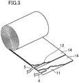
FIG. 3 illustrates a method of manufacturing a sensor body of the humidity sensor. -
FIG. 4 is a graph showing a change with time of a current detected by a sensor of an example and a sensor of a comparative example when salt water is dropped. -
FIG. 5 is a perspective view of a humidity sensor having a sensor surface covered with a coating, the coating partially cut out. -
FIG. 6 illustrates an example of a corrosion test for an automobile. -
FIG. 7 is a perspective view illustrating another example of the humidity sensor. -
FIG. 8 is a perspective view showing still another example of the humidity sensor. - Embodiments of the present disclosure will be described with reference to the drawings. The following description of preferred embodiments is only an example in nature, and is not intended to limit the scope, applications or use of the present disclosure.
- A
humidity sensor 1 shown inFIG. 1 includes asensor body 2, from which leadwires sensor body 2 to apower supply 8 and anammeter 3. Thesensor body 2 has a cylindrical shape, and one end surface thereof serves as asensor surface 6. A peripheral surface of thesensor body 2 orthogonal to thesensor surface 6, and the other end surface of thesensor body 2 are covered with an embeddingresin layer 7. - As can be seen from the
sensor surface 6 shown inFIG. 2 , thesensor body 2 of this embodiment includes metal foil of the same kind, namely,iron foil First iron foil 11 as a first conductive material andsecond iron foil 12 as a second conductive material are wound in a spiral fashion with an insulating layer (resin) 13 interposed therebetween. Winding these materials in this manner forms thesensor body 2 in which thefirst iron foil 11 and thesecond iron foil 12 are alternately stacked with the insulating layer interposed therebetween. An outcrop of thesensor body 2 in which layers (edges) of thefirst iron foil 11, thesecond iron foil 12, and the insulatinglayer 13 are exposed serves as thesensor surface 6. - In
FIG. 2 , the hatching is merely added to distinguish theiron foil 11 and theiron foil 12 from the insulatinglayer 13, and does not represent their cross sections. - One
lead wire 4 is connected to thefirst iron foil 11, and theother lead wire 5 is connected to thesecond iron foil 12. - As shown in
FIG. 3 , an insulatingmaterial 14, thesecond iron foil 12, and another insulatingmaterial 14 are stacked on thefirst iron foil 11 in this order, and they are wound in a spiral fashion to form thesensor body 2. The insulatingmaterials 14 each forming the insulatinglayer 13 can be applied to the surfaces of thefirst iron foil 11 and thesecond iron foil 12, respectively. Alternatively, instead of applying the insulating material, the insulating material in the shape of a thin film may be wound together with thefirst iron foil 11 and thesecond iron foil 12. - Each of the
lead wires first iron foil 11 or thesecond iron foil 12. In the illustrated example, thelead wires first iron foil 11 and thesecond iron foil 12. However, one of the lead wires may be provided on the end portion to be wound first of the corresponding foil, and the other lead wire may be provided on the end portion to be wound last of the corresponding foil. - After the
first iron foil 11, thesecond iron foil 12, and the insulatingmaterials 14 are wound in a spiral fashion and solidified with an embedding resin, the outcrop is polished so that the irregularities of thesensor surface 6 can be reduced to less than 1 µm. - In a preferred embodiment, each of the
first iron foil 11, thesecond iron foil 12, and the insulatinglayer 13 has a thickness of not less than 1 µm and not more than 100 µm. In a more preferred embodiment, the thickness is not less than 10 µm and not more than 80 µm. In an even more preferred embodiment, the thickness is not less than 20 µm and not more than 50 µm. - The
lead wires humidity sensor 1 were connected to thepower supply 8 and the ammeter 3 (serial connection of thefirst iron foil 11, thesecond iron foil 12, thepower supply 8, and the ammeter). With a voltage of 1.5 V applied between thefirst iron foil 11 and thesecond iron foil 12, salt water was intermittently dropped by 10 µL on thesensor surface 6 to see the change in a current value with time. Each of thefirst iron foil 11, thesecond iron foil 12, and the insulatinglayer 13 of thehumidity sensor 1 of this example had a thickness of not more than 20 µm and not more than 50 µm.FIG. 4 shows the measurement results of this sensor together with those of a comparative example (a commercially available sensor). An ACM sensor manufactured by Syrinx. Inc. was used as the commercially available sensor of the comparative example. - Referring to
FIG. 4 , the comparative example (commercially available sensor) showed almost no rise of the current value, even when the salt water was dropped. In contrast, thehumidity sensor 1 of the example showed a rise of the current value every time the salt water was dropped, indicating that the detection sensitivity is high. In the example, the current value gradually increased when the salt water was dropped. This is because a portion of thesensor surface 6 on which the salt water was dropped became wet, and then the wet area gradually spread toward its periphery (the range of a short circuit caused by the salt water between thefirst iron foil 11 and thesecond iron foil 12 was widened). The rise in the current value stopped thereafter, meaning that the spread of the wet area by the salt water stopped. - As shown in
FIG. 5 , a coating (an antirust coating for a metal product) 21 is formed on thesensor surface 6 of thehumidity sensor 1. Thelead wires humidity sensor 1 are connected to thepower supply 8 and theammeter 3, and a voltage is applied between thefirst iron foil 11 and thesecond iron foil 12. In a corrosive environment, a current generated as a result of a short circuit caused between thefirst iron foil 11 and thesecond iron foil 12 exposed on thesensor surface 6 by a corrosion factor that has penetrated thecoating 21 is measured. Since the current is generated by the corrosion factor such as water that has penetrated thecoating 21 and reached thesensor surface 6, whether the current is detected or not and the change in the current value with time can be used as evaluation indices of the degree of corrosiveness of the environment under thecoating 21. - As shown in
FIG. 6 , thehumidity sensors 1 are arranged on a plurality of parts of an automobile 25 (in the illustrated example, afender 26, afloor bottom surface 27, and a rear wheel house 28), and connected to the power supply and acurrent measuring device 29. The sensor surface of eachhumidity sensor 1 is covered with the same coating as that applied to the corresponding part. Then, data of the current that changes with time due to an environmental change accompanying the travel of theautomobile 25 and that is detected by eachhumidity sensor 1 is acquired. - This makes it possible to evaluate the time-varying changes in the degree of the corrosiveness of the environment under the coating on each part of the automobile accompanying the use of the
automobile 25, which is advantageous for the design of an antirust structure and the design of the coating. -
FIG. 7 shows a foldedhumidity sensor 1. In thishumidity sensor 1, asensor body 2 includes an insulating film (insulating material) 15 folded in a zigzag shape, and two or more sheets offirst iron foil 11 and two or more sheets ofsecond iron foil 12 alternately inserted between the folds from both sides thereof. Just like in the foregoing embodiment, an embeddingresin layer 7 covers a surface opposite to thesensor surface 6, and a peripheral surface, of thesensor body 2. - The two or more sheets of
first iron foil 11 forming thesensor body 2 are connected to asingle lead wire 4, and the two or more sheets ofsecond iron foil 12 forming thesensor body 2 are connected to asingle lead wire 5. -
FIG. 8 shows a simply stackedhumidity sensor 1. In thishumidity sensor 1, two or more sheets offirst iron foil 11 and two or more sheets ofsecond iron foil 12 are alternately stacked one by one with an insulating film (insulating material) 15 interposed therebetween to form asensor body 2. Just like in the foregoing embodiment, an embeddingresin layer 7 covers a surface opposite to thesensor surface 6, and a peripheral surface, of thesensor body 2. - The two or more sheets of
first iron foil 11 forming thesensor body 2 are connected to asingle lead wire 4, and the two or more sheets ofsecond iron foil 12 forming thesensor body 2 are connected to asingle lead wire 5. - In the
humidity sensors 1 of the above-described embodiments, the irregularities of thesensor surface 6 are reduced so that the humidity sensor is used as a corrosion sensor with a coating formed on thesensor surface 6. However, if the humidity sensor is used to detect humidity without forming the coating, thesensor surface 6 may have some irregularities.
Claims (10)
- A humidity sensor comprising:a sensor body including a first conductive material and a second conductive material which are alternately stacked with an insulating material interposed therebetween; andlead wires respectively connected to the first and second conductive materials to connect the first and second conductive materials to a power supply and an ammeter, whereinthe sensor body has an outcrop in which a layer of the first conductive material and a layer of the second conductive material are alternately exposed with a layer of the insulating material interposed therebetween, the outcrop serving as a sensor surface, andthe power supply applies a voltage between the first and second conductive materials so that humidity is detected based on a current which flows when a short circuit is caused between the first and second conductive materials by humidity on the sensor surface.
- The humidity sensor of claim 1, wherein
the first and second conductive materials are wound in a spiral fashion with the insulating material interposed therebetween to form the sensor body. - The humidity sensor of claim 1 or 2, wherein
the sensor surface has irregularities of less than 1 µm. - The humidity sensor of any one of claims 1 to 3, wherein
the insulating material has a thickness of not less than 1 µm and not more than 100 µm. - The humidity sensor of claim 4, wherein
each of the first and second conductive materials has a thickness of not less than 1 µm and not more than 100 µm. - The humidity sensor of any one of claims 1 to 5, wherein
an embedding resin layer is provided on a peripheral surface of the sensor body. - A corrosion resistance test method using the humidity sensor of any one of claims 1 to 6 as a corrosion sensor, the method comprising:forming a coating on the sensor surface of the humidity sensor;connecting the lead wires of the humidity sensor to a power supply and an ammeter; andmeasuring, in a corrosive environment, a current generated as a result of a short circuit caused between the first and second conductive materials exposed on the sensor surface by a corrosion factor that has penetrated coating.
- The method of claim 7, wherein
the voltage applied between the first and second conductive materials is not less than 0.1 V and not more than 20 V. - The method of claim 7, wherein
the coating is identical to a coating applied to parts of an automobile. - The method of claim 9, wherein
the humidity sensor is arranged on some of the parts of the automobile and covered with a coating covering the some of the parts, and data of the current that changes with time due to an environmental change accompanying travel of the automobile is acquired.
Applications Claiming Priority (1)
| Application Number | Priority Date | Filing Date | Title |
|---|---|---|---|
| JP2018094898A JP2019200142A (en) | 2018-05-16 | 2018-05-16 | Moisture sensor and corrosion test method using the same |
Publications (1)
| Publication Number | Publication Date |
|---|---|
| EP3570007A1 true EP3570007A1 (en) | 2019-11-20 |
Family
ID=66542017
Family Applications (1)
| Application Number | Title | Priority Date | Filing Date |
|---|---|---|---|
| EP19173250.2A Withdrawn EP3570007A1 (en) | 2018-05-16 | 2019-05-08 | Humidity sensor and corrosion test method using the same |
Country Status (4)
| Country | Link |
|---|---|
| US (1) | US20190353581A1 (en) |
| EP (1) | EP3570007A1 (en) |
| JP (1) | JP2019200142A (en) |
| CN (1) | CN110501283A (en) |
Cited By (1)
| Publication number | Priority date | Publication date | Assignee | Title |
|---|---|---|---|---|
| US11275017B2 (en) * | 2019-08-06 | 2022-03-15 | Saudi Arabian Oil Company | Holiday testing circuit for coated surface inspection |
Families Citing this family (1)
| Publication number | Priority date | Publication date | Assignee | Title |
|---|---|---|---|---|
| WO2024252289A1 (en) * | 2023-06-06 | 2024-12-12 | Auckland Uniservices Limited | Laminate for a sensor device, method of using the same and method of manufacturing the same |
Citations (6)
| Publication number | Priority date | Publication date | Assignee | Title |
|---|---|---|---|---|
| US4442422A (en) * | 1982-03-31 | 1984-04-10 | Murata Manufacturing Co., Ltd. | Humidity sensitive resistor |
| JP2010133748A (en) | 2008-12-02 | 2010-06-17 | Mitsubishi Heavy Ind Ltd | Outdoor structure and method of estimating deterioration of component member of outdoor structure |
| EP2339325A2 (en) * | 2009-12-28 | 2011-06-29 | Mitsubishi Heavy Industries | Corrosion sensor for outdoor structure |
| US20110175633A1 (en) * | 2008-12-02 | 2011-07-21 | Shinsaku Dobashi | Outdoor structure and method of estimating deterioration of constituent member of outdoor structure |
| US20140152449A1 (en) * | 2012-12-05 | 2014-06-05 | International Business Machines Corporation | Early Detection of Environmental Conditions That Will Lead to Creep Corrosion on Printed Circuit Boards in Data Centers |
| US20150293046A1 (en) * | 2014-04-09 | 2015-10-15 | International Business Machines Corporation | Salt-Based Device and a Circuit to Monitor and Log the Times a Data Center Air Goes Above a Predefined Limit |
Family Cites Families (1)
| Publication number | Priority date | Publication date | Assignee | Title |
|---|---|---|---|---|
| CN105758787A (en) * | 2016-04-26 | 2016-07-13 | 南方电网科学研究院有限责任公司 | A corrosion rate measuring device and measuring method |
-
2018
- 2018-05-16 JP JP2018094898A patent/JP2019200142A/en active Pending
-
2019
- 2019-05-06 CN CN201910370931.3A patent/CN110501283A/en active Pending
- 2019-05-07 US US16/404,914 patent/US20190353581A1/en not_active Abandoned
- 2019-05-08 EP EP19173250.2A patent/EP3570007A1/en not_active Withdrawn
Patent Citations (6)
| Publication number | Priority date | Publication date | Assignee | Title |
|---|---|---|---|---|
| US4442422A (en) * | 1982-03-31 | 1984-04-10 | Murata Manufacturing Co., Ltd. | Humidity sensitive resistor |
| JP2010133748A (en) | 2008-12-02 | 2010-06-17 | Mitsubishi Heavy Ind Ltd | Outdoor structure and method of estimating deterioration of component member of outdoor structure |
| US20110175633A1 (en) * | 2008-12-02 | 2011-07-21 | Shinsaku Dobashi | Outdoor structure and method of estimating deterioration of constituent member of outdoor structure |
| EP2339325A2 (en) * | 2009-12-28 | 2011-06-29 | Mitsubishi Heavy Industries | Corrosion sensor for outdoor structure |
| US20140152449A1 (en) * | 2012-12-05 | 2014-06-05 | International Business Machines Corporation | Early Detection of Environmental Conditions That Will Lead to Creep Corrosion on Printed Circuit Boards in Data Centers |
| US20150293046A1 (en) * | 2014-04-09 | 2015-10-15 | International Business Machines Corporation | Salt-Based Device and a Circuit to Monitor and Log the Times a Data Center Air Goes Above a Predefined Limit |
Cited By (1)
| Publication number | Priority date | Publication date | Assignee | Title |
|---|---|---|---|---|
| US11275017B2 (en) * | 2019-08-06 | 2022-03-15 | Saudi Arabian Oil Company | Holiday testing circuit for coated surface inspection |
Also Published As
| Publication number | Publication date |
|---|---|
| US20190353581A1 (en) | 2019-11-21 |
| CN110501283A (en) | 2019-11-26 |
| JP2019200142A (en) | 2019-11-21 |
Similar Documents
| Publication | Publication Date | Title |
|---|---|---|
| EP3570006A2 (en) | Humidity sensor and corrosion test method using the same | |
| US7313947B2 (en) | Corrosion sensing microsensors | |
| JP4880750B2 (en) | Corrosion sensor | |
| EP2288899B1 (en) | Corrosion sensors | |
| US9097745B2 (en) | Corrosion detection apparatus for monitoring a state of corrosion | |
| CN101842689A (en) | Humidity sensor based on progressive corrosion of exposed material | |
| US20070159187A1 (en) | Corrosion detection apparatus and method | |
| US20190353581A1 (en) | Humidity sensor and corrosion test method using the same | |
| EP3173778A1 (en) | Dryness/wetness response sensor having high-speed response and high sensitivity | |
| WO2012031181A9 (en) | Methods and devices for sensing corrosion under insulation (cui) | |
| JP2013533566A (en) | Touch surface and manufacturing method thereof | |
| US20060002815A1 (en) | Corrosion sensing microsensors | |
| US20170122896A1 (en) | Electrode arrangements for test element integrity | |
| JP7128566B2 (en) | Corrosion sensor and corrosion detection method | |
| JP2013134111A (en) | Method for measuring corrosion speed of object | |
| JP6756466B2 (en) | Corrosion sensor and corrosion detection method | |
| EP4197760A9 (en) | Method for producing and monitoring structural composite bodies, and structural composite bodies | |
| KR101293077B1 (en) | Corrosion sensor and method of sensing corrosion | |
| EP2124035A1 (en) | Corrosion sensors | |
| US8400172B2 (en) | Degradation sensor | |
| JP7077761B2 (en) | Electrolytic property test sensor, electrodeposition test method using the sensor, and test equipment | |
| US20250076182A1 (en) | Portable and non-destructive corrosion monitoring systems | |
| JPH1068679A (en) | Method for detecting fatigue damage in structural members | |
| SI25796A (en) | Resistance sensor, manufacturing process of such a sensor and such sensors comprising a device for monitoring the corrosion of the supporting parts of the vehicle during its use | |
| KR20180075785A (en) | High level humidity sensing method using water charge layer |
Legal Events
| Date | Code | Title | Description |
|---|---|---|---|
| PUAI | Public reference made under article 153(3) epc to a published international application that has entered the european phase |
Free format text: ORIGINAL CODE: 0009012 |
|
| STAA | Information on the status of an ep patent application or granted ep patent |
Free format text: STATUS: THE APPLICATION HAS BEEN PUBLISHED |
|
| AK | Designated contracting states |
Kind code of ref document: A1 Designated state(s): AL AT BE BG CH CY CZ DE DK EE ES FI FR GB GR HR HU IE IS IT LI LT LU LV MC MK MT NL NO PL PT RO RS SE SI SK SM TR |
|
| AX | Request for extension of the european patent |
Extension state: BA ME |
|
| STAA | Information on the status of an ep patent application or granted ep patent |
Free format text: STATUS: REQUEST FOR EXAMINATION WAS MADE |
|
| 17P | Request for examination filed |
Effective date: 20200507 |
|
| RBV | Designated contracting states (corrected) |
Designated state(s): AL AT BE BG CH CY CZ DE DK EE ES FI FR GB GR HR HU IE IS IT LI LT LU LV MC MK MT NL NO PL PT RO RS SE SI SK SM TR |
|
| STAA | Information on the status of an ep patent application or granted ep patent |
Free format text: STATUS: THE APPLICATION IS DEEMED TO BE WITHDRAWN |
|
| 18D | Application deemed to be withdrawn |
Effective date: 20211201 |