EP3569924B1 - Scheinwerfer für ein kraftfahrzeug - Google Patents
Scheinwerfer für ein kraftfahrzeug Download PDFInfo
- Publication number
- EP3569924B1 EP3569924B1 EP19172999.5A EP19172999A EP3569924B1 EP 3569924 B1 EP3569924 B1 EP 3569924B1 EP 19172999 A EP19172999 A EP 19172999A EP 3569924 B1 EP3569924 B1 EP 3569924B1
- Authority
- EP
- European Patent Office
- Prior art keywords
- compensation
- headlamp
- light module
- light
- axis
- Prior art date
- Legal status (The legal status is an assumption and is not a legal conclusion. Google has not performed a legal analysis and makes no representation as to the accuracy of the status listed.)
- Active
Links
Images


Classifications
-
- F—MECHANICAL ENGINEERING; LIGHTING; HEATING; WEAPONS; BLASTING
- F21—LIGHTING
- F21S—NON-PORTABLE LIGHTING DEVICES; SYSTEMS THEREOF; VEHICLE LIGHTING DEVICES SPECIALLY ADAPTED FOR VEHICLE EXTERIORS
- F21S45/00—Arrangements within vehicle lighting devices specially adapted for vehicle exteriors, for purposes other than emission or distribution of light
- F21S45/10—Protection of lighting devices
-
- B—PERFORMING OPERATIONS; TRANSPORTING
- B60—VEHICLES IN GENERAL
- B60Q—ARRANGEMENT OF SIGNALLING OR LIGHTING DEVICES, THE MOUNTING OR SUPPORTING THEREOF OR CIRCUITS THEREFOR, FOR VEHICLES IN GENERAL
- B60Q1/00—Arrangement of optical signalling or lighting devices, the mounting or supporting thereof or circuits therefor
- B60Q1/02—Arrangement of optical signalling or lighting devices, the mounting or supporting thereof or circuits therefor the devices being primarily intended to illuminate the way ahead or to illuminate other areas of way or environments
- B60Q1/04—Arrangement of optical signalling or lighting devices, the mounting or supporting thereof or circuits therefor the devices being primarily intended to illuminate the way ahead or to illuminate other areas of way or environments the devices being headlights
- B60Q1/06—Arrangement of optical signalling or lighting devices, the mounting or supporting thereof or circuits therefor the devices being primarily intended to illuminate the way ahead or to illuminate other areas of way or environments the devices being headlights adjustable, e.g. remotely-controlled from inside vehicle
- B60Q1/08—Arrangement of optical signalling or lighting devices, the mounting or supporting thereof or circuits therefor the devices being primarily intended to illuminate the way ahead or to illuminate other areas of way or environments the devices being headlights adjustable, e.g. remotely-controlled from inside vehicle automatically
- B60Q1/10—Arrangement of optical signalling or lighting devices, the mounting or supporting thereof or circuits therefor the devices being primarily intended to illuminate the way ahead or to illuminate other areas of way or environments the devices being headlights adjustable, e.g. remotely-controlled from inside vehicle automatically due to vehicle inclination, e.g. due to load distribution
- B60Q1/115—Arrangement of optical signalling or lighting devices, the mounting or supporting thereof or circuits therefor the devices being primarily intended to illuminate the way ahead or to illuminate other areas of way or environments the devices being headlights adjustable, e.g. remotely-controlled from inside vehicle automatically due to vehicle inclination, e.g. due to load distribution by electric means
Definitions
- the invention relates to a headlight for a motor vehicle.
- EP 2 719 579 A2 already relates to a headlight according to the preamble of claim 1. It is known that headlights are constructed using suitable material selection and mechanical design in order to keep the expected effects of the influence of temperature as low as possible.
- thermocompensation section which forms a longitudinal expansion section which changes when the Temperature can change in a compensation length.
- DE 10 2011 003910 A1 relates to a headlight of a motor vehicle with two bearing arrangements which form an axis of rotation about which a component or an assembly of the headlight can be pivoted.
- the rotatable mounting of a light module is required to implement headlight range control, dynamic cornering lights and/or partial high beam.
- the bearing arrangement is formed between a holding frame of the light module and a headlight housing.
- EP 2 280 221 A2 discloses a headlight for a motor vehicle with a housing in which at least one light module is accommodated in a predetermined position.
- the light module is arranged in the housing of the headlight via receiving means.
- the housing has at least one attachment point in which the housing is connected to a frame element of the motor vehicle.
- EN 10 2009 035565 A1 relates to a headlight for a motor vehicle with a housing in which a light module is accommodated in a predetermined position.
- the holder of the light module has a compensation element for compensating thermally induced deviations of the position of the light module from the predetermined position in the headlight.
- the headlight offers the possibility of at least partially compensating for the very product-specific temperature-dependent positional changes of the beam light distribution by adjusting the compensation device through the temperature-dependent correction of the rotation position.
- the headlight provided advantageously ensures the positional stability of the beam light distribution even at different temperatures. This is achieved by a simple mechanical chain of action of the headlight range adjustment device. Electronic adjustment of the drive depending on a measured temperature is therefore no longer necessary.
- An advantageous embodiment is characterized in that the compensation device is arranged in a force transmission section between the light module frame and the drive.
- the arrangement of the drive in the headlight is thus advantageously dependent on the function of the Compensation device is decoupled.
- the power transmission section thus includes the correction function of the compensation device.
- the compensation device comprises: a first compensation section with a first thermal expansion coefficient, and a second compensation section with a second thermal expansion coefficient that is different from the first thermal expansion coefficient.
- Different thermal expansion coefficients of the material or the material composition of the compensation sections are advantageously used to compensate for the temperature-related change in position of the emitted light distribution.
- a distal connecting section connects the first and second compensation sections to one another.
- two effective temperature-dependent length expansions of the connecting sections are coupled to one another and the temperature compensation is achieved using a small installation space volume.
- first and the second compensation section have mutually corresponding regions for producing the distal connection section along a central longitudinal axis of the compensation device.
- the distal connection section can thus be selected at the end of a temperature design of the headlight type, taking into account the different temperature-dependent linear expansions effective along the central longitudinal axis.
- An advantageous embodiment is characterized in that a first proximal connecting section connects the first compensation section to the drive, and a second proximal connecting section connects the second compensation section to the light module frame.
- the proximal connecting sections advantageously create a structurally simple arrangement.
- the first and/or the second compensation section have subsections with different thermal expansion coefficients.
- one of the subsections can advantageously be designed to be interchangeable in the manner of a modular system in order to provide suitable temperature compensation for the respective headlight type.
- An advantageous embodiment is characterized in that an imaginary central longitudinal axis of the compensation device runs at least in sections along an imaginary tangent, wherein the imaginary tangent touches an imaginary circular cylinder surface with the headlight range axis as the cylinder axis.
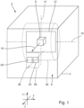
- FIG. 1 shows a headlight 2 for a motor vehicle in schematic form.
- the headlight 2 comprises a headlight housing 4, the light exit opening of which is closed with a cover plate 6.
- a light module 8 is arranged within the headlight housing 4, which is designed to emit a beam light distribution 10 in the direction of travel x.
- the light module 8 is a low beam module, the low beam distribution of which includes a light-dark boundary that is clearly visible on a measuring screen.
- the light module 8 is arranged in a light module frame 12, whereby both a rigid design of the connection between the light module 8 and the light module frame 12 can be provided and, alternatively, the light module 8 can be rotatable about a cornering light axis 14.
- the light module frame 12 is in turn fixed to the headlight housing 4 so that it can rotate about a beam range axis 16.
- the beam range of the beam light distribution 10 is adjusted by the rotation about the beam range axis 16.
- a vertical position of the light-dark boundary of the beam light distribution 10 is adjusted by a rotation about the headlight range axis 16.
- a headlight range adjustment device 20 is arranged between the headlight housing 4 and the light module frame 12 which can be rotated about the headlight range axis 16.
- the headlight range adjustment device 20 includes a drive 22 and a compensation device 24.
- the drive 22 is for example, an electric motor and is driven by means of a control signal in such a way that a rotational position of the light module frame 12 about the headlight range axis 16 is adjusted via a gear.
- the compensation device 24 at least partially compensates for temperature-related changes in the position of the light module 8 and thus also temperature-related vertical changes in the position of the light distribution 10 emitted by the headlight 2.
- the temperature-related changes in the position of the light module 8 are due to the geometries, materials and their interaction in the chain of action between the light module frame 12 and light module 8 or its individual components.
- the compensation device 24 has an imaginary central longitudinal axis 26, which coincides with an imaginary tangent of an imaginary circular cylinder jacket 28, the circular cylinder jacket 28 having an imaginary cylinder axis, which coincides with the headlight range axis 16.
- the imaginary central longitudinal axis 26 runs parallel to the direction of travel x.
- the drive 22 is directly or indirectly rigidly connected to the headlight housing 4 and the compensation device 24 is located along a mechanical active path between the drive 22 and the light module frame 12.
- the drive 22 is controlled and moved by means of the compensation device 24 the light module frame 12.
- the compensation device 24 is part of a power transmission section and thus part of the transmission between the light module frame 12 and the drive 22.
- the compensation device 24 directly or indirectly rigidly connected to the headlight housing 4 on one side and indirectly or directly rigidly connected to the drive 22.
- the compensation device 24 corrects the rotational position of the light module frame 12, which is adjusted by a torque introduced into the light module frame 12 by the drive 22.
- Figure 2 shows in schematic form the compensation device 24 with a first compensation section 30 and a second compensation section 32, which have different temperature expansion coefficients and are arranged, for example, parallel to one another.
- the two compensation sections 30 and 32 cannot be arranged parallel to one another, but then have directions of action parallel to one another.
- the first and second compensation sections 30, 32 are connected to one another in a distal connecting section 34.
- the first compensation section has a first proximal connection section 36, which connects the first compensation section 30 to the drive.
- the second compensation section 32 has a second proximal connection section 38, which connects the second compensation section 32 to the light module frame 12. Due to the different temperature expansion coefficients of the two compensation sections 30 and 32, the connecting sections 36 and 38 move relative to one another along the central longitudinal axis 26. To make this shift dependent on the temperature in one manufacturing step Both of them have to be taken into account
- Compensation sections 30 and 32 have mutually corresponding regions for producing a respective distal connecting section 34b and 34c.
- the proximal connecting sections 36 are displaced relative to one another along the central longitudinal axis 26 in such a way that the correction of the rotational position of the light module frame 12 results.
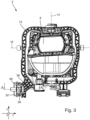
- Figure 3 shows a view of the headlight 2 against the direction of travel x.
- a cornering light function is also implemented in order to rotate the light module 8 about the cornering light axis 14.
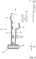
- Figure 4 shows a schematic section AA from Figure 3 .
- a bolt 404 is inserted into the distal connecting section 34 in order to connect the two compensation sections 30 and 32 to one another.
- a region 406 is shown in which the two compensation sections 30 and 32 can also be connected to one another in order to achieve temperature compensation of the temperature-related shift of the light-dark boundary in the vertical direction.
- Figure 5 shows a schematic section of an embodiment of the compensation device 24 not according to the invention.
- the compensation device 24 is arranged between the drive 22 and the light module frame 12.
- the second compensation section 32 projects into a recess 504 of a cup-shaped receptacle 506 in section, the first compensation section 30 being part of the cup-shaped receptacle 506.
- Figure 6 shows a schematic section of an embodiment of the compensation device 24 according to the invention.
- the second compensation section 32 is constructed in several parts and comprises a first subsection 602 and a second subsection 604, wherein both subsections have a different thermal expansion coefficient from one another.
Landscapes
- Engineering & Computer Science (AREA)
- General Engineering & Computer Science (AREA)
- Mechanical Engineering (AREA)
- Non-Portable Lighting Devices Or Systems Thereof (AREA)
- Lighting Device Outwards From Vehicle And Optical Signal (AREA)
Description
- Die Erfindung betrifft einen Scheinwerfer für ein Kraftfahrzeug.
-
EP 2 719 579 A2 betrifft bereits einen Scheinwerfer gemäß dem Oberbegriff von Anspruch 1. Aus Es ist bekannt, dass Scheinwerfer mittels geeigneter Materialauswahl und mechanischer Auslegung derart konstruiert werden, um die zu erwartenden Auswirkungen eines Einflusses der Temperatur so gering wie möglich zu halten. - Auch ist bekannt, dass der Trend zu immer höher auflösenden Scheinwerfern geht, womit die Hell-Dunkel-Grenze bei einer Abblendlichtverteilung deutlicher hervortritt.
- In
DE 10 2012 111311 A1 ist ein Thermokompensationsabschnitt offenbart, der einen Längendehnungsabschnitt bildet, der sich bei Änderung der Temperatur in einer Kompensationslänge ändern kann. -
DE 10 2011 003910 A1 betrifft einen Scheinwerfer eines Kraftfahrzeugs mit zwei Lageranordnungen, die eine Drehachse bilden, um die eine Komponente oder eine Baugruppe des Scheinwerfers schwenkbar ist. Dabei ist die drehbare Lagerung eines Lichtmoduls zur Realisierung einer Leuchtweitenregelung, eines dynamischen Kurvenlichts und/oder eines Teilfernlichts erforderlich. Die Lageranordnung ist zwischen einem Halterahmen des Lichtmoduls und einem Scheinwerfergehäuse ausgebildet. -
DE 10 2011 000735 A1 betrifft einen Wärmeausdehnungskompensator und einen Scheinwerfer. -
EP 2 280 221 A2 offenbart einen Scheinwerfer für ein Kraftfahrzeug mit einem Gehäuse, in dem wenigstens ein Lichtmodul in einer vorgegebenen Lage aufgenommen ist. Das Lichtmodul ist über Aufnahmemittel im Gehäuse des Scheinwerfers angeordnet. Das Gehäuse weist zumindest einen Befestigungspunkt auf, in dem das Gehäuse mit einem Rahmenelement des Kraftfahrzeugs verbunden ist. -
DE 10 2009 035565 A1 betrifft einen Scheinwerfer für ein Kraftfahrzeug mit einem Gehäuse, in dem ein Lichtmodul in einer vorgegebenen Lage aufgenommen ist. Die Aufnahme des Lichtmoduls weist ein Ausgleichselement zum Ausgleich von thermisch bedingten Abweichungen der Lage des Lichtmoduls von der vorgegebenen Lage im Scheinwerfer auf. - Aus der
DE 10 2012 219 032 A1 ist eine Leuchtweitenregelung bekannt. - Es ist also Aufgabe der Erfindung, hohe Anforderungen an die Lagestabilität der Abstrahllichtverteilung auch bei unterschiedlichen Temperaturen zu erfüllen.
- Die Aufgabe wird durch einen Scheinwerfer nach dem Anspruch 1 gelöst. Vorteilhafte Ausführungsformen finden sich in den Unteransprüchen sowie in der nachfolgenden Beschreibung.
- Die Lagestabilität der Abstrahllichtverteilung ist im Konstruktionsprozess des Scheinwerfers nicht in voller Gänze vorhersagbar. Folglich bietet der bereitgestellte Scheinwerfer die Möglichkeit, durch die Anpassung der Kompensationsvorrichtung die sehr produktspezifischen temperaturabhängigen Lageänderungen der Abstrahllichtverteilung zumindest zu einem Teil durch die temperaturabhängige Korrektur der Rotationsposition zu kompensieren.
- Vorteilhaft wird durch den bereitgestellten Scheinwerfer die Lagestabilität der Abstrahllichtverteilung auch bei unterschiedlichen Temperaturen gewährleistet. Dies wird durch eine einfache mechanische Wirkkette der Leuchtweiteneinstellvorrichtung erreicht. Eine elektronische Nachstellung des Antriebs in Abhängigkeit von einer gemessenen Temperatur kann somit entfallen.
- Die gesetzlich vorgeschriebene Einhaltung der Lage der Hell-Dunkel-Grenze in einer abgestrahlten Abblendlichtverteilung wird folglich verbessert.
- Mithin wird eine kostengünstige und konstruktiv einfache Möglichkeit geschaffen, um die Lagestabilität der Abstrahllichtverteilung eines Lichtmoduls auch bei unterschiedlichen Temperaturen zu gewährleisten.
- Eine vorteilhafte Ausführungsform zeichnet sich dadurch aus, dass die Kompensationsvorrichtung in einem Kraftübertragungsabschnitt zwischen dem Lichtmodulrahmen und dem Antrieb angeordnet ist. Vorteilhaft wird damit die Anordnung des Antriebs im Scheinwerfer von der Funktion der Kompensationsvorrichtung entkoppelt. Der Kraftübertragungsabschnitt umfasst damit die Korrekturfunktion der Kompensationsvorrichtung.
- Die Kompensationsvorrichtung umfasst: einen ersten Kompensationsabschnitt mit einem ersten Temperaturausdehnungskoeffizienten, und einen zweiten Kompensationsabschnitt mit einem zweiten von dem ersten Temperaturausdehnungskoeffizienten unterschiedlichen Temperaturausdehnungskoeffizienten. Vorteilhaft werden unterschiedliche Temperaturausdehnungskoeffizienten des Materials bzw. der Materialzusammensetzung der Kompensationsabschnitte dazu genutzt um die temperaturbedingte Lageänderung der Abstrahllichtverteilung zu kompensieren.
- Ein distaler Verbindungsabschnitt verbindet den ersten und den zweiten Kompensationsabschnitt miteinander. Durch das Vorsehen des distalen Verbindungsabschnitts werden zwei wirksame temperaturabhängige Längenausdehnungen der Verbindungsabschnitte miteinander gekoppelt und die Temperaturkompensation unter Ausnutzung eines geringen Bauraumvolumens erreicht.
- Eine vorteilhafte Ausführungsform zeichnet sich dadurch aus, dass der erste und der zweite Kompensationsabschnitt entlang einer Mittenlängsachse der Kompensationsvorrichtung zueinander korrespondierende Bereiche zur Herstellung des distalen Verbindungsabschnitts aufweisen. Vorteilhaft kann damit zum Ende einer Temperaturauslegung des Scheinwerfertyps der distale Verbindungsabschnitt unter Berücksichtigung der unterschiedlichen entlang der Mittenlängsachse wirksamen temperaturabhängigen Längenausdehnungen ausgewählt werden.
- Eine vorteilhafte Ausführungsform zeichnet sich dadurch aus, dass ein erster proximaler Verbindungsabschnitt den ersten Kompensationsabschnitt mit dem Antrieb verbindet, und wobei ein zweiter proximaler Verbindungsabschnitt den zweiten Kompensationsabschnitt mit dem Lichtmodulrahmen verbindet. Vorteilhaft wird mit den proximalen Verbindungsabschnitten eine konstruktiv einfache Anordnung geschaffen.
- Der erste und/oder der zweite Kompensationsabschnitt weisen Unterabschnitte mit voneinander unterschiedlichen Temperaturausdehnungskoeffizienten auf. Vorteilhaft kann beispielsweise einer der Unterabschnitte nach Art eines Baukastensystems austauschbar gestaltet werden, um für den jeweiligen Scheinwerfertyp eine passende Temperaturkompensation bereitzustellen.
- Eine vorteilhafte Ausführungsform zeichnet sich dadurch aus, dass eine gedachte Mittenlängsachse der Kompensationsvorrichtung zumindest abschnittsweise entlang einer gedachten Tangente verläuft, wobei die gedachte Tangente eine gedachte Kreiszylindermantelfläche mit der Leuchtweitenachse als Zylinderachse berührt. Vorteilhaft werden damit die unterschiedlichen Temperaturausdehnungskoeffizienten und deren Auswirkung auf die Einstellung der Abstrahllichtverteilung bauraumsparend ausgenutzt.
- Weitere Merkmale und Vorteile sind in der nachfolgenden Beschreibung der Zeichnung erläutert. In der Zeichnung zeigen:
- Figur 1
- einen Scheinwerfer in schematischer Form;
- Figur 2
- eine Kompensationsvorrichtung in schematischer Form;
- Figur 3
- den Scheinwerfer in eine Fronansicht; und
- Figur 4, 5 und 6
- jeweils einen schematischen Schnitt einer Kompensationsvorrichtung, wobei
Fig. 6 die erfindungsgemäße Unterabschnitte zeigt. -
Figur 1 zeigt in schematischer Form einen Scheinwerfer 2 für ein Kraftfahrzeug. Der Scheinwerfer 2 umfasst ein Scheinwerfergehäuse 4, dessen Lichtaustrittsöffnung mit einer Abdeckscheibe 6 verschlossen ist. Innerhalb des Scheinwerfergehäuses 4 ist ein Lichtmodul 8 angeordnet, welches zur Abstrahlung einer Abstrahllichtverteilung 10 in Fahrtrichtung x ausgebildet ist. Insbesondere ist das Lichtmodul 8 ein Abblendlichtmodul, dessen Abblendlichtverteilung eine auf einem Messschirm sich deutlich abzeichnende Hell-Dunkel-Grenze umfasst. Das Lichtmodul 8 ist in einem Lichtmodulrahmen 12 angeordnet, wobei sowohl eine starre Ausführung der Verbindung zwischen Lichtmodul 8 und Lichtmodulrahmen 12 vorgesehen sein kann als auch alternativ eine Rotierbarkeit des Lichtmoduls 8 um eine Kurvenlichtachse 14 vorgesehen sein kann. Der Lichtmodulrahmen 12 wiederum ist um eine Leuchtweitenachse 16 rotierbar zu dem Scheinwerfergehäuse 4 festgelegt. Durch die Rotation um die Leuchtweitenachse 16 wird die Leuchtweite der Abstrahllichtverteilung 10 eingestellt. Insbesondere eine vertikale Position der Hell-Dunkel-Grenze der Abstrahllichtverteilung 10 wird durch eine Rotation um die Leuchtweitenachse 16 eingestellt. - Eine Leuchtweiteneinstellvorrichtung 20 ist zwischen dem Scheinwerfergehäuse 4 und dem um die Leuchtweitenachse 16 rotierbaren Lichtmodulrahmen 12 angeordnet. Die Leuchtweiteneinstellvorrichtung 20 umfasst einen Antrieb 22 und eine Kompensationsvorrichtung 24. Der Antrieb 22 ist beispielsweise ein Elektromotor und wird mittels eines Steuersignals so angetrieben, dass über ein Getriebe eine Rotationsposition des Lichtmodulrahmens 12 um die Leuchtweitenachse 16 eingestellt wird. In der jeweiligen Rotationsposition kompensiert die Kompensationsvorrichtung 24 zumindest teilweise temperaturbedingte Lageveränderungen des Lichtmoduls 8 und damit auch temperaturbedingte vertikale Lageveränderungen der vom Scheinwerfer 2 abgestrahlten Abstrahllichtverteilung 10. Die temperaturbedingten Lageveränderungen des Lichtmoduls 8 sind durch die Geometrien, Materialien und deren Zusammenspiel in der Wirkkette zwischen Lichtmodulrahmen 12 und Lichtmodul 8 bzw. dessen Einzelkomponenten bedingt.
- Die Kompensationsvorrichtung 24 weist eine gedachte Mittenlängsachse 26 auf, welche mit einer gedachten Tangente eines gedachten Kreiszylindermantels 28 zusammenfällt, wobei der Kreiszylindermantel 28 eine gedachte Zylinderachse aufweist, welche mit der Leuchtweitenachse 16 zusammenfällt. Beispielsweise verläuft die gedachte Mittenlängsachse 26 parallel zur Fahrtrichtung x.
- In einem ersten Beispiel ist der Antrieb 22 mittelbar oder unmittelbar starr mit dem Scheinwerfergehäuse 4 verbunden und die Kompensationsvorrichtung 24 befindet sich entlang eines mechanischen Wirkpfades zwischen dem Antrieb 22 und dem Lichtmodulrahmen 12. Zu einer Leuchtweiteneinstellung wird der Antrieb 22 angesteuert und bewegt mittels der Kompensationsvorrichtung 24 den Lichtmodulrahmen 12. Die Kompensationsvorrichtung 24 ist Teil eines Kraftübertragungsabschnitts und damit Teil des Getriebes zwischen dem Lichtmodulrahmen 12 und dem Antrieb 22.
- In einem zweiten Beispiel ist die Kompensationsvorrichtung 24 mittelbar oder unmittelbar starr mit dem Scheinwerfergehäuse 4 zur einen Seite und mittelbar oder unmittelbar starr mit dem Antrieb 22 verbunden.
- Die Kompensationsvorrichtung 24 korrigiert die Rotationsposition des Lichtmodulrahmens 12, welche durch ein von dem Antrieb 22 in den Lichtmodulrahmen 12 eingeleitetes Moment eingestellt wird.
-
Figur 2 zeigt in schematischer Form die Kompensationseinrichtung 24 mit einem ersten Kompensationsabschnitt 30 und einem zweiten Kompensationsabschnitt 32, welche voneinander unterschiedliche Temperaturausdehnungskoeffizienten aufweisen und beispielsweise parallel zueinander angeordnet sind. Selbstverständlich können die beiden Kompensationsabschnitte 30 und 32 auch nicht parallel zueinander angeordnet sein, weisen dann aber zueinander parallele Wirkrichtungen auf. - Der erste und der zweite Kompensationsabschnitt 30, 32 sind in einem distalen Verbindungsabschnitt 34 miteinander verbunden. In proximaler Richtung weist der erste Kompensationsabschnitt einen ersten proximalen Verbindungsabschnitt 36 auf, welcher den ersten Kompensationsabschnitt 30 mit dem Antrieb verbindet. Der zweite Kompensationsabschnitt 32 weist einen zweiten proximalen Verbindungsabschnitt 38 auf, welcher den zweiten Kompensationsabschnitt 32 mit dem Lichtmodulrahmen 12 verbindet. Durch die unterschiedlichen Temperaturausdehnungskoeffizienten der beiden Kompensationsabschnitte 30 und 32 verschieben sich die Verbindungsabschnitte 36 und 38 entlang der Mittenlängsachse 26 zueinander. Um diese Verschiebung in Abhängigkeit von der Temperatur in einem Fertigungsschritt zu berücksichtigen weisen die beiden
- Kompensationsabschnitte 30 und 32 zueinander korrespondierende Bereiche zur Herstellung eines jeweiligen distalen Verbindungsabschnitts 34b und 34c auf.
- Durch die unterschiedlichen Kontraktions- bzw. Expansionslängen der beiden Kompensationsabschnitte 30, 32, welche sich parallel zur Mittenlängsachse 26 bei einer jeweiligen Temperatur ergeben, werden die proximalen Verbindungsabschnitt 36 entlang der Mittenlängsachse 26 so zueinander verschoben, dass sich die Korrektur der Rotationsposition des Lichtmodulrahmens 12 ergibt.
-
Figur 3 zeigt eine Sicht auf den Scheinwerfer 2 entgegen der Fahrtrichtung x. Im vorliegenden Beispiel ist auch eine Kurvenlichtfunktion realisiert, um das Lichtmodul 8 um die Kurvenlichtachse 14 zu rotieren. -
Figur 4 zeigt einen schematischen Schnitt A-A ausFigur 3 . In dem distalen Verbindungsabschnitt 34 ist ein Bolzen 404 eingebracht, um die beiden Kompensationsabschnitte 30 und 32 miteinander zu verbinden. Es ist ein Bereich 406 gezeigt, in dem die beiden Kompensationsabschnitte 30 und 32 ebenfalls mit einander verbindbar sind, um die Temperaturkompensation der temperaturbedingten Verschiebung der Hell-Dunkel-Grenze in vertikaler Richtung zu erreichen. -
Figur 5 zeigt einen schematischen Schnitt einer nicht erfindungsgemäßen Ausführungsform der Kompensationsvorrichtung 24. In diesem Beispiel ist die Kompensationsvorrichtung 24 zwischen dem Antrieb 22 und dem Lichtmodulrahmen 12 angeordnet. Hierbei ragt der zweite Kompensationsabschnitt 32 in eine Ausnehmung 504 einer im Schnitt becher-förmigen Aufnahme 506 hinein, wobei der erste Kompensationsabschnitt 30 Teil der becher-förmigen Aufnahme 506 ist. -
Figur 6 zeigt einen schematischen Schnitt einer erfindungsgemäßen Ausführungsform der Kompensationsvorrichtung 24. Im Unterschied zuFigur 5 ist der zweite Kompensationsabschnitt 32 mehrteilig aufgebaut und umfasst einen ersten Unterabschnitt 602 und einen zweiten Unterabschnitt 604, wobei beide Unterabschnitte einen voneinander unterschiedlichen Temperaturausdehnungskoeffizienten aufweisen.
Claims (7)
- Ein Scheinwerfer (2) für ein Kraftfahrzeug, wobei der Scheinwerfer (2) umfasst:ein Scheinwerfergehäuse (4);ein Lichtmodul (8) zur Erzeugung einer Abstrahllichtverteilung (10), insbesondere einer Abblendlichtverteilung umfassend eine Hell-Dunkel-Grenze;einen Lichtmodulrahmen (12), an welchem das Lichtmodul (8) starr oder um eine Kurvenlichtachse (14) rotierbar festgelegt ist, und welcher um eine Leuchtweitenachse (16) rotierbar zu dem Scheinwerfergehäuse (4) festgelegt ist;eine zu dem Scheinwerfergehäuse (4) starr festgelegte Leuchtweiteneinstellvorrichtung (20) mit einem Antrieb (22) zur Einstellung einer Rotationsposition des Lichtmodulrahmens (12) um die Leuchtweitenachse (16) und mit einer Kompensationsvorrichtung (24),dadurch gekennzeichnet, dass dieKompensationseinrichtung temperaturabhängig die Rotationsposition des Lichtmodulrahmens (12) korrigiert,wobei die Kompensationsvorrichtung (20) umfasst:einen ersten Kompensationsabschnitt (30) mit einem ersten Temperaturausdehnungskoeffizienten, undeinen zweiten Kompensationsabschnitt (32) mit einem zweiten von dem ersten Temperaturausdehnungskoeffizienten unterschiedlichen Temperaturausdehnungskoeffizienten,wobei ein distaler Verbindungsabschnitt (34) den ersten und den zweiten Kompensationsabschnitt (30, 32) miteinander verbindet,der erste und/oder der zweite Kompensationsabschnitt (32) Unterabschnitte (602, 604) mit voneinander unterschiedlichen Temperaturausdehnungskoeffizienten aufweist.
- Der Scheinwerfer (2) nach dem Anspruch 1, wobei die Kompensationsvorrichtung (24) in einem Kraftübertragungsabschnitt zwischen dem Lichtmodulrahmen (12) und dem Antrieb (22) angeordnet ist.
- Der Scheinwerfer (2) nach Anspruch 1 oder 2, wobei die beiden Kompensationsabschnitte (30, 32) entweder- parallel zueinander angeordnet sind oder- nicht parallel zueinander angeordnet sind und zueinander parallele Wirkrichtungen aufweisen.
- Der Scheinwerfer (2) nach einem der Ansprüche 1 bis 3, wobei der erste und der zweite Kompensationsabschnitt (30, 32) entlang einer Mittenlängsachse (26) der Kompensationsvorrichtung (20) zueinander korrespondierende Bereiche zur Herstellung des distalen Verbindungsabschnitts (34) aufweisen.
- Der Scheinwerfer (2) nach einem der Ansprüche 1 bis 4, wobei in dem distalen Verbindungsabschnitt (34) ein Bolzen (404) eingebracht ist, um die beiden Kompensationsabschnitte (30 und 32) miteinander zu verbinden.
- Der Scheinwerfer (2) nach einem der Ansprüche 2 bis 5, wobei ein erster proximaler Verbindungsabschnitt (36) den ersten Kompensationsabschnitt (30) mit dem Antrieb (22) verbindet, und wobei ein zweiter proximaler Verbindungsabschnitt (38) den zweiten Kompensationsabschnitt (32) mit dem Lichtmodulrahmen (12) verbindet.
- Der Scheinwerfer (2) nach einem der Ansprüche 1 bis 6, wobei die gedachte Mittenlängsachse (26) der Kompensationsvorrichtung (20) zumindest abschnittsweise entlang einer gedachten Tangente verläuft, wobei die gedachte Tangente eine gedachte Kreiszylindermantelfläche (28) mit der Leuchtweitenachse (16) als Zylinderachse berührt.
Applications Claiming Priority (1)
| Application Number | Priority Date | Filing Date | Title |
|---|---|---|---|
| DE102018111414.1A DE102018111414A1 (de) | 2018-05-14 | 2018-05-14 | Scheinwerfer für ein Kraftfahrzeug |
Publications (2)
| Publication Number | Publication Date |
|---|---|
| EP3569924A1 EP3569924A1 (de) | 2019-11-20 |
| EP3569924B1 true EP3569924B1 (de) | 2024-04-03 |
Family
ID=66448377
Family Applications (1)
| Application Number | Title | Priority Date | Filing Date |
|---|---|---|---|
| EP19172999.5A Active EP3569924B1 (de) | 2018-05-14 | 2019-05-07 | Scheinwerfer für ein kraftfahrzeug |
Country Status (2)
| Country | Link |
|---|---|
| EP (1) | EP3569924B1 (de) |
| DE (1) | DE102018111414A1 (de) |
Families Citing this family (1)
| Publication number | Priority date | Publication date | Assignee | Title |
|---|---|---|---|---|
| DE102020122354A1 (de) * | 2020-08-26 | 2022-03-03 | Marelli Automotive Lighting Reutlingen (Germany) GmbH | Kraftfahrzeugscheinwerfer mit einem temperaturabhängig seine Form ändernden Stellelement |
Citations (1)
| Publication number | Priority date | Publication date | Assignee | Title |
|---|---|---|---|---|
| EP2719579A2 (de) * | 2012-10-10 | 2014-04-16 | Zizala Lichtsysteme GmbH | Scheinwerfer für ein Kraftfahrzeug |
Family Cites Families (6)
| Publication number | Priority date | Publication date | Assignee | Title |
|---|---|---|---|---|
| DE102009035565B4 (de) * | 2009-07-31 | 2024-12-24 | HELLA GmbH & Co. KGaA | Scheinwerfer für ein Kraftfahrzeug mit verbesserter Temperaturkompensation |
| DE102009035563A1 (de) * | 2009-07-31 | 2011-02-03 | Hella Kgaa Hueck & Co. | Temperaturkompensierte Aufnahme eines Lichtmoduls in einem Gehäuse eines Scheinwerfers |
| DE102011003910B4 (de) * | 2011-02-10 | 2016-02-18 | Automotive Lighting Reutlingen Gmbh | Scheinwerfer eines Kraftfahrzeugs |
| DE102011000735B4 (de) * | 2011-02-15 | 2016-02-25 | Hella Kgaa Hueck & Co. | Wärmeausdehnungskompensator und Scheinwerfer |
| DE102012219032B4 (de) | 2012-10-18 | 2021-11-04 | Automotive Lighting Reutlingen Gmbh | Verfahren und Vorrichtung zur dynamischen Leuchtweitenregulierung eines Scheinwerfers eines Kraftfahrzeugs |
| DE102012111311A1 (de) * | 2012-11-23 | 2014-05-28 | Hella Kgaa Hueck & Co. | Aufnahmeanordnung eines Lichtmoduls im Gehäuse eines Scheinwerfers |
-
2018
- 2018-05-14 DE DE102018111414.1A patent/DE102018111414A1/de not_active Withdrawn
-
2019
- 2019-05-07 EP EP19172999.5A patent/EP3569924B1/de active Active
Patent Citations (1)
| Publication number | Priority date | Publication date | Assignee | Title |
|---|---|---|---|---|
| EP2719579A2 (de) * | 2012-10-10 | 2014-04-16 | Zizala Lichtsysteme GmbH | Scheinwerfer für ein Kraftfahrzeug |
Also Published As
| Publication number | Publication date |
|---|---|
| DE102018111414A1 (de) | 2019-11-14 |
| EP3569924A1 (de) | 2019-11-20 |
Similar Documents
| Publication | Publication Date | Title |
|---|---|---|
| DE102007053430B4 (de) | Beleuchtungsvorrichtung für Fahrzeuge und Einstellvorrichtung für die optische Achse einer Beleuchtungsvorrichtung für Fahrzeuge | |
| DE69804135T2 (de) | Getriebemotor zum antrieb von autozubehör, mit mittel zur beseitigung des axialspiels seiner achse | |
| EP2693108B1 (de) | Lichtmodul und Verfahren zur Herstellung eines Lichtmoduls | |
| DE3125746C2 (de) | Schrauben-Differentialbetätigungseinrichtung | |
| EP3235679B1 (de) | Getriebe für eine verstelleinrichtung in fahrzeugen zum verstellen zweier zueinander verstellbarer fahrzeugteile | |
| DE10131735A1 (de) | Parksperre für Fahrzeuggetriebe | |
| WO2009090018A1 (de) | Lenksäule mit kunststoffgleithülse | |
| DE10327103A1 (de) | Untersetzungsgetriebe, insbesondere für eine Verstellvorrichtung eines Kraftfahrzeugsitzes | |
| WO2013178302A1 (de) | Lenksäule für ein kraftfahrzeug | |
| WO2001049554A1 (de) | Stellglied für eine fahrzeug-lenkvorrichtung | |
| EP3569924B1 (de) | Scheinwerfer für ein kraftfahrzeug | |
| EP2714470B1 (de) | Baugruppe zur verstellung des aussenspiegels | |
| EP2605939B1 (de) | Scheibenwischvorrichtung | |
| EP3523556A1 (de) | Getriebe sowie kopfstütze mit wenigstens einem elektrischen antrieb, umfassend ein getriebe | |
| EP1548482B1 (de) | Mikroskopobjektiv mit axial verstellbaren Korrekturfassungen | |
| EP3960542B1 (de) | Kraftfahrzeugscheinwerfer mit einem temperaturabhängig seine form ändernden stellelement | |
| DE102006017132A1 (de) | Scheinwerfer für Fahrzeuge | |
| DE102005002606B4 (de) | Vorrichtung zum Andrücken einer Zahnstange an ein mit der Zahnstange in Eingriff stehendes Ritzel | |
| DE102018211785A1 (de) | Einstellelement zum Ausgleichen von Toleranzen sowie Befestigungsanordnung mit einem solchen Einstellelement | |
| DE102021102631B4 (de) | Beleuchtungsvorrichtung für ein Fahrzeug | |
| DE102014008697A1 (de) | Verfahren und Einstellwerkzeug zum Einstellen einer Position eines Heckdeckels an einem Kraftfahrzeug | |
| EP0742357B1 (de) | Spritzverstelleinrichtung für Einspritzpumpendüsen und Verfahren zu deren Justieren | |
| WO2014056570A1 (de) | Zahnstangelenkgetriebe | |
| DE102004050834B4 (de) | Positionsmesseinrichtung | |
| DE102021133068A1 (de) | Schaltgabel für ein Gangstellermodul eines Kraftfahrzeugs sowie Verfahren zur Herstellung einer Schaltgabel |
Legal Events
| Date | Code | Title | Description |
|---|---|---|---|
| PUAI | Public reference made under article 153(3) epc to a published international application that has entered the european phase |
Free format text: ORIGINAL CODE: 0009012 |
|
| STAA | Information on the status of an ep patent application or granted ep patent |
Free format text: STATUS: THE APPLICATION HAS BEEN PUBLISHED |
|
| AK | Designated contracting states |
Kind code of ref document: A1 Designated state(s): AL AT BE BG CH CY CZ DE DK EE ES FI FR GB GR HR HU IE IS IT LI LT LU LV MC MK MT NL NO PL PT RO RS SE SI SK SM TR |
|
| AX | Request for extension of the european patent |
Extension state: BA ME |
|
| STAA | Information on the status of an ep patent application or granted ep patent |
Free format text: STATUS: REQUEST FOR EXAMINATION WAS MADE |
|
| 17P | Request for examination filed |
Effective date: 20200520 |
|
| RBV | Designated contracting states (corrected) |
Designated state(s): AL AT BE BG CH CY CZ DE DK EE ES FI FR GB GR HR HU IE IS IT LI LT LU LV MC MK MT NL NO PL PT RO RS SE SI SK SM TR |
|
| STAA | Information on the status of an ep patent application or granted ep patent |
Free format text: STATUS: EXAMINATION IS IN PROGRESS |
|
| 17Q | First examination report despatched |
Effective date: 20220125 |
|
| GRAP | Despatch of communication of intention to grant a patent |
Free format text: ORIGINAL CODE: EPIDOSNIGR1 |
|
| STAA | Information on the status of an ep patent application or granted ep patent |
Free format text: STATUS: GRANT OF PATENT IS INTENDED |
|
| INTG | Intention to grant announced |
Effective date: 20231108 |
|
| GRAS | Grant fee paid |
Free format text: ORIGINAL CODE: EPIDOSNIGR3 |
|
| GRAA | (expected) grant |
Free format text: ORIGINAL CODE: 0009210 |
|
| STAA | Information on the status of an ep patent application or granted ep patent |
Free format text: STATUS: THE PATENT HAS BEEN GRANTED |
|
| AK | Designated contracting states |
Kind code of ref document: B1 Designated state(s): AL AT BE BG CH CY CZ DE DK EE ES FI FR GB GR HR HU IE IS IT LI LT LU LV MC MK MT NL NO PL PT RO RS SE SI SK SM TR |
|
| RAP3 | Party data changed (applicant data changed or rights of an application transferred) |
Owner name: MARELLI AUTOMOTIVE LIGHTING REUTLINGEN (GERMANY) GMBH |
|
| REG | Reference to a national code |
Ref country code: GB Ref legal event code: FG4D Free format text: NOT ENGLISH |
|
| REG | Reference to a national code |
Ref country code: CH Ref legal event code: EP |
|
| REG | Reference to a national code |
Ref country code: DE Ref legal event code: R096 Ref document number: 502019010940 Country of ref document: DE |
|
| REG | Reference to a national code |
Ref country code: IE Ref legal event code: FG4D Free format text: LANGUAGE OF EP DOCUMENT: GERMAN |
|
| REG | Reference to a national code |
Ref country code: LT Ref legal event code: MG9D |
|
| REG | Reference to a national code |
Ref country code: NL Ref legal event code: MP Effective date: 20240403 |
|
| PG25 | Lapsed in a contracting state [announced via postgrant information from national office to epo] |
Ref country code: NL Free format text: LAPSE BECAUSE OF FAILURE TO SUBMIT A TRANSLATION OF THE DESCRIPTION OR TO PAY THE FEE WITHIN THE PRESCRIBED TIME-LIMIT Effective date: 20240403 |
|
| PG25 | Lapsed in a contracting state [announced via postgrant information from national office to epo] |
Ref country code: NL Free format text: LAPSE BECAUSE OF FAILURE TO SUBMIT A TRANSLATION OF THE DESCRIPTION OR TO PAY THE FEE WITHIN THE PRESCRIBED TIME-LIMIT Effective date: 20240403 |
|
| PG25 | Lapsed in a contracting state [announced via postgrant information from national office to epo] |
Ref country code: IS Free format text: LAPSE BECAUSE OF FAILURE TO SUBMIT A TRANSLATION OF THE DESCRIPTION OR TO PAY THE FEE WITHIN THE PRESCRIBED TIME-LIMIT Effective date: 20240803 |
|
| PG25 | Lapsed in a contracting state [announced via postgrant information from national office to epo] |
Ref country code: BG Free format text: LAPSE BECAUSE OF FAILURE TO SUBMIT A TRANSLATION OF THE DESCRIPTION OR TO PAY THE FEE WITHIN THE PRESCRIBED TIME-LIMIT Effective date: 20240403 |
|
| PG25 | Lapsed in a contracting state [announced via postgrant information from national office to epo] |
Ref country code: HR Free format text: LAPSE BECAUSE OF FAILURE TO SUBMIT A TRANSLATION OF THE DESCRIPTION OR TO PAY THE FEE WITHIN THE PRESCRIBED TIME-LIMIT Effective date: 20240403 Ref country code: FI Free format text: LAPSE BECAUSE OF FAILURE TO SUBMIT A TRANSLATION OF THE DESCRIPTION OR TO PAY THE FEE WITHIN THE PRESCRIBED TIME-LIMIT Effective date: 20240403 |
|
| PG25 | Lapsed in a contracting state [announced via postgrant information from national office to epo] |
Ref country code: GR Free format text: LAPSE BECAUSE OF FAILURE TO SUBMIT A TRANSLATION OF THE DESCRIPTION OR TO PAY THE FEE WITHIN THE PRESCRIBED TIME-LIMIT Effective date: 20240704 |
|
| PG25 | Lapsed in a contracting state [announced via postgrant information from national office to epo] |
Ref country code: PT Free format text: LAPSE BECAUSE OF FAILURE TO SUBMIT A TRANSLATION OF THE DESCRIPTION OR TO PAY THE FEE WITHIN THE PRESCRIBED TIME-LIMIT Effective date: 20240805 |
|
| PG25 | Lapsed in a contracting state [announced via postgrant information from national office to epo] |
Ref country code: ES Free format text: LAPSE BECAUSE OF FAILURE TO SUBMIT A TRANSLATION OF THE DESCRIPTION OR TO PAY THE FEE WITHIN THE PRESCRIBED TIME-LIMIT Effective date: 20240403 |
|
| PG25 | Lapsed in a contracting state [announced via postgrant information from national office to epo] |
Ref country code: CZ Free format text: LAPSE BECAUSE OF FAILURE TO SUBMIT A TRANSLATION OF THE DESCRIPTION OR TO PAY THE FEE WITHIN THE PRESCRIBED TIME-LIMIT Effective date: 20240403 |
|
| PG25 | Lapsed in a contracting state [announced via postgrant information from national office to epo] |
Ref country code: PL Free format text: LAPSE BECAUSE OF FAILURE TO SUBMIT A TRANSLATION OF THE DESCRIPTION OR TO PAY THE FEE WITHIN THE PRESCRIBED TIME-LIMIT Effective date: 20240403 |
|
| PG25 | Lapsed in a contracting state [announced via postgrant information from national office to epo] |
Ref country code: LV Free format text: LAPSE BECAUSE OF FAILURE TO SUBMIT A TRANSLATION OF THE DESCRIPTION OR TO PAY THE FEE WITHIN THE PRESCRIBED TIME-LIMIT Effective date: 20240403 |
|
| PG25 | Lapsed in a contracting state [announced via postgrant information from national office to epo] |
Ref country code: PT Free format text: LAPSE BECAUSE OF FAILURE TO SUBMIT A TRANSLATION OF THE DESCRIPTION OR TO PAY THE FEE WITHIN THE PRESCRIBED TIME-LIMIT Effective date: 20240805 Ref country code: PL Free format text: LAPSE BECAUSE OF FAILURE TO SUBMIT A TRANSLATION OF THE DESCRIPTION OR TO PAY THE FEE WITHIN THE PRESCRIBED TIME-LIMIT Effective date: 20240403 Ref country code: NO Free format text: LAPSE BECAUSE OF FAILURE TO SUBMIT A TRANSLATION OF THE DESCRIPTION OR TO PAY THE FEE WITHIN THE PRESCRIBED TIME-LIMIT Effective date: 20240703 Ref country code: LV Free format text: LAPSE BECAUSE OF FAILURE TO SUBMIT A TRANSLATION OF THE DESCRIPTION OR TO PAY THE FEE WITHIN THE PRESCRIBED TIME-LIMIT Effective date: 20240403 Ref country code: IS Free format text: LAPSE BECAUSE OF FAILURE TO SUBMIT A TRANSLATION OF THE DESCRIPTION OR TO PAY THE FEE WITHIN THE PRESCRIBED TIME-LIMIT Effective date: 20240803 Ref country code: HR Free format text: LAPSE BECAUSE OF FAILURE TO SUBMIT A TRANSLATION OF THE DESCRIPTION OR TO PAY THE FEE WITHIN THE PRESCRIBED TIME-LIMIT Effective date: 20240403 Ref country code: GR Free format text: LAPSE BECAUSE OF FAILURE TO SUBMIT A TRANSLATION OF THE DESCRIPTION OR TO PAY THE FEE WITHIN THE PRESCRIBED TIME-LIMIT Effective date: 20240704 Ref country code: FI Free format text: LAPSE BECAUSE OF FAILURE TO SUBMIT A TRANSLATION OF THE DESCRIPTION OR TO PAY THE FEE WITHIN THE PRESCRIBED TIME-LIMIT Effective date: 20240403 Ref country code: ES Free format text: LAPSE BECAUSE OF FAILURE TO SUBMIT A TRANSLATION OF THE DESCRIPTION OR TO PAY THE FEE WITHIN THE PRESCRIBED TIME-LIMIT Effective date: 20240403 Ref country code: CZ Free format text: LAPSE BECAUSE OF FAILURE TO SUBMIT A TRANSLATION OF THE DESCRIPTION OR TO PAY THE FEE WITHIN THE PRESCRIBED TIME-LIMIT Effective date: 20240403 Ref country code: BG Free format text: LAPSE BECAUSE OF FAILURE TO SUBMIT A TRANSLATION OF THE DESCRIPTION OR TO PAY THE FEE WITHIN THE PRESCRIBED TIME-LIMIT Effective date: 20240403 Ref country code: RS Free format text: LAPSE BECAUSE OF FAILURE TO SUBMIT A TRANSLATION OF THE DESCRIPTION OR TO PAY THE FEE WITHIN THE PRESCRIBED TIME-LIMIT Effective date: 20240703 |
|
| REG | Reference to a national code |
Ref country code: CH Ref legal event code: PL |
|
| REG | Reference to a national code |
Ref country code: DE Ref legal event code: R097 Ref document number: 502019010940 Country of ref document: DE |
|
| PG25 | Lapsed in a contracting state [announced via postgrant information from national office to epo] |
Ref country code: DK Free format text: LAPSE BECAUSE OF FAILURE TO SUBMIT A TRANSLATION OF THE DESCRIPTION OR TO PAY THE FEE WITHIN THE PRESCRIBED TIME-LIMIT Effective date: 20240403 |
|
| PG25 | Lapsed in a contracting state [announced via postgrant information from national office to epo] |
Ref country code: LU Free format text: LAPSE BECAUSE OF NON-PAYMENT OF DUE FEES Effective date: 20240507 |
|
| PG25 | Lapsed in a contracting state [announced via postgrant information from national office to epo] |
Ref country code: EE Free format text: LAPSE BECAUSE OF FAILURE TO SUBMIT A TRANSLATION OF THE DESCRIPTION OR TO PAY THE FEE WITHIN THE PRESCRIBED TIME-LIMIT Effective date: 20240403 |
|
| PG25 | Lapsed in a contracting state [announced via postgrant information from national office to epo] |
Ref country code: RO Free format text: LAPSE BECAUSE OF FAILURE TO SUBMIT A TRANSLATION OF THE DESCRIPTION OR TO PAY THE FEE WITHIN THE PRESCRIBED TIME-LIMIT Effective date: 20240403 Ref country code: SK Free format text: LAPSE BECAUSE OF FAILURE TO SUBMIT A TRANSLATION OF THE DESCRIPTION OR TO PAY THE FEE WITHIN THE PRESCRIBED TIME-LIMIT Effective date: 20240403 |
|
| PG25 | Lapsed in a contracting state [announced via postgrant information from national office to epo] |
Ref country code: SM Free format text: LAPSE BECAUSE OF FAILURE TO SUBMIT A TRANSLATION OF THE DESCRIPTION OR TO PAY THE FEE WITHIN THE PRESCRIBED TIME-LIMIT Effective date: 20240403 |
|
| PG25 | Lapsed in a contracting state [announced via postgrant information from national office to epo] |
Ref country code: SM Free format text: LAPSE BECAUSE OF FAILURE TO SUBMIT A TRANSLATION OF THE DESCRIPTION OR TO PAY THE FEE WITHIN THE PRESCRIBED TIME-LIMIT Effective date: 20240403 Ref country code: SK Free format text: LAPSE BECAUSE OF FAILURE TO SUBMIT A TRANSLATION OF THE DESCRIPTION OR TO PAY THE FEE WITHIN THE PRESCRIBED TIME-LIMIT Effective date: 20240403 Ref country code: RO Free format text: LAPSE BECAUSE OF FAILURE TO SUBMIT A TRANSLATION OF THE DESCRIPTION OR TO PAY THE FEE WITHIN THE PRESCRIBED TIME-LIMIT Effective date: 20240403 Ref country code: LU Free format text: LAPSE BECAUSE OF NON-PAYMENT OF DUE FEES Effective date: 20240507 Ref country code: EE Free format text: LAPSE BECAUSE OF FAILURE TO SUBMIT A TRANSLATION OF THE DESCRIPTION OR TO PAY THE FEE WITHIN THE PRESCRIBED TIME-LIMIT Effective date: 20240403 Ref country code: DK Free format text: LAPSE BECAUSE OF FAILURE TO SUBMIT A TRANSLATION OF THE DESCRIPTION OR TO PAY THE FEE WITHIN THE PRESCRIBED TIME-LIMIT Effective date: 20240403 Ref country code: CH Free format text: LAPSE BECAUSE OF NON-PAYMENT OF DUE FEES Effective date: 20240531 Ref country code: MC Free format text: LAPSE BECAUSE OF FAILURE TO SUBMIT A TRANSLATION OF THE DESCRIPTION OR TO PAY THE FEE WITHIN THE PRESCRIBED TIME-LIMIT Effective date: 20240403 |
|
| PLBE | No opposition filed within time limit |
Free format text: ORIGINAL CODE: 0009261 |
|
| STAA | Information on the status of an ep patent application or granted ep patent |
Free format text: STATUS: NO OPPOSITION FILED WITHIN TIME LIMIT |
|
| REG | Reference to a national code |
Ref country code: BE Ref legal event code: MM Effective date: 20240531 |
|
| 26N | No opposition filed |
Effective date: 20250106 |
|
| GBPC | Gb: european patent ceased through non-payment of renewal fee |
Effective date: 20240703 |
|
| PG25 | Lapsed in a contracting state [announced via postgrant information from national office to epo] |
Ref country code: IE Free format text: LAPSE BECAUSE OF NON-PAYMENT OF DUE FEES Effective date: 20240507 |
|
| PG25 | Lapsed in a contracting state [announced via postgrant information from national office to epo] |
Ref country code: SI Free format text: LAPSE BECAUSE OF FAILURE TO SUBMIT A TRANSLATION OF THE DESCRIPTION OR TO PAY THE FEE WITHIN THE PRESCRIBED TIME-LIMIT Effective date: 20240403 Ref country code: BE Free format text: LAPSE BECAUSE OF NON-PAYMENT OF DUE FEES Effective date: 20240531 |
|
| PG25 | Lapsed in a contracting state [announced via postgrant information from national office to epo] |
Ref country code: FR Free format text: LAPSE BECAUSE OF NON-PAYMENT OF DUE FEES Effective date: 20240603 |
|
| PG25 | Lapsed in a contracting state [announced via postgrant information from national office to epo] |
Ref country code: GB Free format text: LAPSE BECAUSE OF NON-PAYMENT OF DUE FEES Effective date: 20240703 |
|
| PGFP | Annual fee paid to national office [announced via postgrant information from national office to epo] |
Ref country code: DE Payment date: 20250423 Year of fee payment: 7 |
|
| REG | Reference to a national code |
Ref country code: AT Ref legal event code: MM01 Ref document number: 1672687 Country of ref document: AT Kind code of ref document: T Effective date: 20240507 |
|
| PG25 | Lapsed in a contracting state [announced via postgrant information from national office to epo] |
Ref country code: AT Free format text: LAPSE BECAUSE OF NON-PAYMENT OF DUE FEES Effective date: 20240507 |
|
| PG25 | Lapsed in a contracting state [announced via postgrant information from national office to epo] |
Ref country code: CY Free format text: LAPSE BECAUSE OF FAILURE TO SUBMIT A TRANSLATION OF THE DESCRIPTION OR TO PAY THE FEE WITHIN THE PRESCRIBED TIME-LIMIT; INVALID AB INITIO Effective date: 20190507 |
|
| PG25 | Lapsed in a contracting state [announced via postgrant information from national office to epo] |
Ref country code: HU Free format text: LAPSE BECAUSE OF FAILURE TO SUBMIT A TRANSLATION OF THE DESCRIPTION OR TO PAY THE FEE WITHIN THE PRESCRIBED TIME-LIMIT; INVALID AB INITIO Effective date: 20190507 |
|
| PG25 | Lapsed in a contracting state [announced via postgrant information from national office to epo] |
Ref country code: SE Free format text: LAPSE BECAUSE OF FAILURE TO SUBMIT A TRANSLATION OF THE DESCRIPTION OR TO PAY THE FEE WITHIN THE PRESCRIBED TIME-LIMIT Effective date: 20240403 |
|
| REG | Reference to a national code |
Ref country code: DE Ref legal event code: R081 Ref document number: 502019010940 Country of ref document: DE Owner name: MARELLI GERMANY GMBH, DE Free format text: FORMER OWNER: MARELLI AUTOMOTIVE LIGHTING REUTLINGEN (GERMANY) GMBH, 72762 REUTLINGEN, DE |
|
| PG25 | Lapsed in a contracting state [announced via postgrant information from national office to epo] |
Ref country code: IT Free format text: LAPSE BECAUSE OF FAILURE TO SUBMIT A TRANSLATION OF THE DESCRIPTION OR TO PAY THE FEE WITHIN THE PRESCRIBED TIME-LIMIT Effective date: 20240403 |