EP3569912A1 - Supporting system for quick couplings, particularly for flat face cartridges couplings - Google Patents
Supporting system for quick couplings, particularly for flat face cartridges couplings Download PDFInfo
- Publication number
- EP3569912A1 EP3569912A1 EP18425034.8A EP18425034A EP3569912A1 EP 3569912 A1 EP3569912 A1 EP 3569912A1 EP 18425034 A EP18425034 A EP 18425034A EP 3569912 A1 EP3569912 A1 EP 3569912A1
- Authority
- EP
- European Patent Office
- Prior art keywords
- bracket
- seat
- couplings
- hydraulic
- turned
- Prior art date
- Legal status (The legal status is an assumption and is not a legal conclusion. Google has not performed a legal analysis and makes no representation as to the accuracy of the status listed.)
- Granted
Links
Images



Classifications
-
- F—MECHANICAL ENGINEERING; LIGHTING; HEATING; WEAPONS; BLASTING
- F16—ENGINEERING ELEMENTS AND UNITS; GENERAL MEASURES FOR PRODUCING AND MAINTAINING EFFECTIVE FUNCTIONING OF MACHINES OR INSTALLATIONS; THERMAL INSULATION IN GENERAL
- F16L—PIPES; JOINTS OR FITTINGS FOR PIPES; SUPPORTS FOR PIPES, CABLES OR PROTECTIVE TUBING; MEANS FOR THERMAL INSULATION IN GENERAL
- F16L37/00—Couplings of the quick-acting type
- F16L37/56—Couplings of the quick-acting type for double-walled or multi-channel pipes or pipe assemblies
-
- F—MECHANICAL ENGINEERING; LIGHTING; HEATING; WEAPONS; BLASTING
- F16—ENGINEERING ELEMENTS AND UNITS; GENERAL MEASURES FOR PRODUCING AND MAINTAINING EFFECTIVE FUNCTIONING OF MACHINES OR INSTALLATIONS; THERMAL INSULATION IN GENERAL
- F16L—PIPES; JOINTS OR FITTINGS FOR PIPES; SUPPORTS FOR PIPES, CABLES OR PROTECTIVE TUBING; MEANS FOR THERMAL INSULATION IN GENERAL
- F16L39/00—Joints or fittings for double-walled or multi-channel pipes or pipe assemblies
-
- F—MECHANICAL ENGINEERING; LIGHTING; HEATING; WEAPONS; BLASTING
- F16—ENGINEERING ELEMENTS AND UNITS; GENERAL MEASURES FOR PRODUCING AND MAINTAINING EFFECTIVE FUNCTIONING OF MACHINES OR INSTALLATIONS; THERMAL INSULATION IN GENERAL
- F16L—PIPES; JOINTS OR FITTINGS FOR PIPES; SUPPORTS FOR PIPES, CABLES OR PROTECTIVE TUBING; MEANS FOR THERMAL INSULATION IN GENERAL
- F16L41/00—Branching pipes; Joining pipes to walls
- F16L41/001—Branching pipes; Joining pipes to walls the wall being a pipe plate
-
- E—FIXED CONSTRUCTIONS
- E02—HYDRAULIC ENGINEERING; FOUNDATIONS; SOIL SHIFTING
- E02F—DREDGING; SOIL-SHIFTING
- E02F9/00—Component parts of dredgers or soil-shifting machines, not restricted to one of the kinds covered by groups E02F3/00 - E02F7/00
- E02F9/20—Drives; Control devices
- E02F9/22—Hydraulic or pneumatic drives
- E02F9/2264—Arrangements or adaptations of elements for hydraulic drives
- E02F9/2275—Hoses and supports therefor and protection therefor
Definitions
- the present invention relates to an improved supporting system for quick couplings, in particular for flat face cartridge couplings in the hydraulic system of operating machines.
- the invention relates to a modular and highly versatile system adaptable to different configurations of use, in particular, but not exclusively, for the use of flat face cartridge couplings for connecting a utility to a hydraulic system of operating machines such as, for example, but not limited to, earth-moving machines or the like.
- the solution according to the present invention consists of a supporting system in which the devices, in particular, as said, the flat face cartridge couplings, are inserted into a turned body, and therefore rapidly manufactured, supported by a bracket, preferably made of steel.
- the advantage is obtained that one has the complete freedom to install the desired number of lines (with the only constraint of the available space), it being possible to modify the arrangement also during use (for example by changing the size of the couplings, or replacing a power line with a drain line, or by removing or adding one or more lines).
- Another advantage of the solution proposed according to the present invention consists in allowing the lines to be coupled with residual pressure both on the machine side and on the equipment side, without having to use decompression systems of the machine hydraulic system, as the decompression of the oil on the machine side occurs during the coupling due to the configuration of the cartridge itself, which provides a decompression system as described for example in patent EP2378177 , by the same Applicant, and the decompressed oil flows through a line that returns it to the tank or passes into a dedicated drain line placed in parallel (with dedicated coupling) through a floating pipe system, and the equipment can thus be coupled after the decompression has taken place.
- a coupling can be used which provides for a pressure elimination system during the connection (for example, series 3 of the same Applicant).
- a specific object of the present invention therefore is a supporting system for quick couplings, in particular for flat face cartridge couplings for connecting hydraulic lines to the hydraulic system of operating machines, said system comprising a bracket, provided with at least one seat, and at least one body, having one end which can be inserted in said at least one seat and the other end configured to accommodate said device, said at least one seat and said at least one body providing means for the fixed orientation of the body in the respective seat, said at least one body comprising two diametrically opposed threaded holes.
- said body is substantially cylindrical provided with an axial seat for accommodating said device, and said diametrically opposed threaded holes are arranged radially on said body.
- said bracket is made of steel, preferably obtained by a laser cutting process, and said body is a turned body.
- said slot has a shape which corresponds to an abutment formed on said body, and the respective fixing is implemented by means of a nut.
- a plug and/or a drainage tube are coupled to connect the lines of the devices mounted on the various bodies, and/or a fitting suitable for connecting the system with other areas of the system.
- said plug is a threaded turned plug, designed specifically by the applicant.
- said drainage tube, or connecting floating tube comprises two turned and threaded adapters screwed into the threaded holes made in the turned body.
- said fitting is a fitting specially designed by the applicant to be able to connect from one end to the turned body and on the other to accommodate the floating tube.
- FIG. 1 a supporting system according to the invention is shown, indicated generically with reference numeral 100 in the various figures, consisting, in its simplest form, of a turned body 1 and a bracket 2.
- the turned body 1 receives the cartridge 3, which in the figure is represented as a flat face cartridge coupling, but which could also be of a different type.
- the bracket 2 may comprise, according to the requirements and the application, one or more seats 4 to receive a corresponding number of bodies 1.
- Each seat 4 of the bracket 2 is made with a shaping configured to receive a corresponding counter-shaping obtained on the part of the body 1 arranged to fit into the seat 4 itself, so as to have a fixed orientation of the body 1 with respect to the seat 4, a feature that, as will be seen hereinafter, is absolutely necessary for the correct operation of the invention.
- the hole of the seat 4 is shaped in a manner corresponding to a respective abutment surface 5 of the body 1, whereby, when they are coupled, the body 1 can no longer rotate with respect to the bracket 2.
- the fixing of the body 1 (and consequently of the cartridge 3 ) to the bracket 2 is accomplished by tightening a nut 8.
- the shaping of the slot 4 and of the abutment 5 allows obtaining a correct relative position, and avoiding the rotation of the body 1 both during assembly and during the work.
- the bracket 2 is symmetrically shaped so that it is possible to mount the cartridges in any position, as shown for example in figures 10 and 11 and can be conveniently installed on the machine arm by means of special fixing slots in which to insert commercially available bolts.
- the body 1 has two diametrically opposed holes 6, 7 threaded and oriented with respect to the shaping of the abutment surface 5 of the body 1 such that, with the body 1 coupled to the bracket 2, the axis of said holes is parallel to the development of the bracket 2.
- the orientation of the holes 6, 7 will remain fixed, with their axis arranged substantially parallel to the direction of development of the bracket 2, vertical according to the orientation shown in the accompanying figures, precisely by virtue of the shaping of the seat 4 and of the shoulder 5.
- the threaded holes 6, 7 are obtained to receive, according to the solution provided, a plug 9 ( figure 3 ) or a specially designed adapter 12 which will mate with the drainage tube 10 ( figures 3 and 4 ) necessary to connect the lines of the cartridges 3 mounted on the various bodies 1 adjacent to the bracket, or a fitting 11 ( figure 4 ), suitable for connecting the system with other areas of the system.
- the plug 9 is preferably a threaded turned plug, which has a seat for an O-ring, so as to guarantee the hydraulic seal.
- the drainage tube 10 or connecting floating tube, comprises two turned and threaded adapters 12 screwed into the threaded holes 6, 7 formed in the turned body 1. Also in this case, an O-ring 13 placed between the adapter and the body 1 is used to guarantee the seal.
- a turned tube 10 is used to allow the passage of oil from one line to another.
- the flotation capacity of the tube 10, with a clearance G, serves to be able to adapt to possible variations in the positioning of the seats 4 made on the bracket 2.
- a further O-ring 14 is provided to ensure the seal between the tube 10 and the adapter 12, even in the presence of axial clearance.
- the fitting 11 is a fitting available from various suppliers, whose sole constraint is that of having a thread that mates with that of the threaded holes 6, 7 of the turned body 1.
- the fitting 11 will provide an O-ring or a metal seal based on the choice of the manufacturer of the operating machine.
- figure 6 shows the use for a single power line, figure 7 for a power line A and a return line B, and figure 8 for a power line A, a return line B and, below, a drainage line C.
- Figure 9 shows a very particular embodiment, which provides for eight bodies 1, a respective cartridge 3 being inserted in each body.
- figures 10 and 11 show applications with female cartridges with assembly in opposite directions while using the same bracket and the same components of the modular system described thus far.
- Another advantage of the present invention lies in the versatility of the system, in particular in relation to the positioning, since it is possible to mount the system on any side and in any position.
- Disassembly and reassembly are also extremely easy, since it is possible to change the position of a power or drain line in an extremely easy way.
- the solution of the steel bracket is much less heavy than the cast iron solution and due to the possibility of being obtained with a laser cutting process, it does not require any investment in the mould.
Landscapes
- Engineering & Computer Science (AREA)
- General Engineering & Computer Science (AREA)
- Mechanical Engineering (AREA)
- Quick-Acting Or Multi-Walled Pipe Joints (AREA)
Abstract
Description
- The present invention relates to an improved supporting system for quick couplings, in particular for flat face cartridge couplings in the hydraulic system of operating machines.
- More in detail, the invention relates to a modular and highly versatile system adaptable to different configurations of use, in particular, but not exclusively, for the use of flat face cartridge couplings for connecting a utility to a hydraulic system of operating machines such as, for example, but not limited to, earth-moving machines or the like.
- Hereinafter, the supporting system according to the invention will be described in detail with reference to its use to flat face cartridge couplings, but it is apparent that the same system can be used to support other devices, according to the needs.
- As is known, in hydraulic systems for operating machines, such as, for example, excavators and earth moving machines in general, the support of cartridge couplings occurs inside cast iron castings. All the various fittings and connections are implemented in the casting body.
- It is immediately clear that this supporting system of cartridge couplings has constraints due to the dimensions and position of the lines.
- Moreover, the same solution of the prior art implies very high production costs, due in particular to the creation of the casting mould and to mechanical machining, which is difficult and expensive in terms of cost and production times.
- Another drawback of the known solutions consists in the very long procurement times, due in particular to difficult production technologies.
- In light of the foregoing, the solution according to the present invention is proposed, which consists of a supporting system in which the devices, in particular, as said, the flat face cartridge couplings, are inserted into a turned body, and therefore rapidly manufactured, supported by a bracket, preferably made of steel.
- In particular, through the use of the bracket, the advantage is obtained that one has the complete freedom to install the desired number of lines (with the only constraint of the available space), it being possible to modify the arrangement also during use (for example by changing the size of the couplings, or replacing a power line with a drain line, or by removing or adding one or more lines).
- Another advantage of the solution proposed according to the present invention consists in allowing the lines to be coupled with residual pressure both on the machine side and on the equipment side, without having to use decompression systems of the machine hydraulic system, as the decompression of the oil on the machine side occurs during the coupling due to the configuration of the cartridge itself, which provides a decompression system as described for example in patent
EP2378177 , by the same Applicant, and the decompressed oil flows through a line that returns it to the tank or passes into a dedicated drain line placed in parallel (with dedicated coupling) through a floating pipe system, and the equipment can thus be coupled after the decompression has taken place. - If, on the other hand, the equipment is not subjected to residual pressure, it will be possible to use a single-valve flat face coupling in the system according to the present invention.
- If the equipment is subject to an increase in residual pressure, due for example to an increase in ambient temperature, a coupling can be used which provides for a pressure elimination system during the connection (for example,
series 3 of the same Applicant). - A specific object of the present invention therefore is a supporting system for quick couplings, in particular for flat face cartridge couplings for connecting hydraulic lines to the hydraulic system of operating machines, said system comprising a bracket, provided with at least one seat, and at least one body, having one end which can be inserted in said at least one seat and the other end configured to accommodate said device, said at least one seat and said at least one body providing means for the fixed orientation of the body in the respective seat, said at least one body comprising two diametrically opposed threaded holes.
- According to a preferred aspect of the invention, said body is substantially cylindrical provided with an axial seat for accommodating said device, and said diametrically opposed threaded holes are arranged radially on said body.
- Preferably, according to the invention, said bracket is made of steel, preferably obtained by a laser cutting process, and said body is a turned body.
- Again according to the invention, said slot has a shape which corresponds to an abutment formed on said body, and the respective fixing is implemented by means of a nut.
- Again according to the invention, in said threaded holes a plug and/or a drainage tube are coupled to connect the lines of the devices mounted on the various bodies, and/or a fitting suitable for connecting the system with other areas of the system.
- Moreover, according to the invention, said plug is a threaded turned plug, designed specifically by the applicant.
- Again according to the invention, said drainage tube, or connecting floating tube, comprises two turned and threaded adapters screwed into the threaded holes made in the turned body.
- Finally, according to the invention, said fitting is a fitting specially designed by the applicant to be able to connect from one end to the turned body and on the other to accommodate the floating tube.
- The present invention will now be described, by way of a non-limiting example, with particular reference to the figures in the accompanying drawings, in which:
-
figure 1 is a view of the supporting system according to the invention, disassembled; -
figure 2 is a perspective view of the supporting system offigure 1 assembled with a cartridge coupling inserted; -
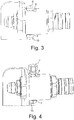
figure 3 is a first side view of the supporting system offigure 1 ; -
figure 4 is a side lateral view of the supporting system offigure 1 ; -
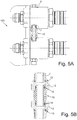
figure 5a is a partially sectional view of the supporting system offigure 1 , assembled; -
figure 5b is a sectional view of a detail offigure 5a ;figure 6 is a perspective view of a first exemplary application of the supporting system according to the invention; -
figure 7 is a perspective view of a second exemplary application of the supporting system according to the invention, in such a figure, B is the return line; -
figure 8 is a perspective view of a third exemplary application of the supporting system according to the invention; infigure 8 , line B is the return line, line C is the drainage line, for the recovery of the oil drained during decompression; -
figure 9 is a perspective view of a fourth exemplary application of the supporting system according to the invention; -
figure 10 is a perspective view of a fifth exemplary application of the supporting system according to the invention; -
figure 11 is a perspective view of a sixth exemplary application of the supporting system according to the invention. - Looking first at
figures 1 to 5 of the accompanying drawings, a supporting system according to the invention is shown, indicated generically withreference numeral 100 in the various figures, consisting, in its simplest form, of a turnedbody 1 and abracket 2. - The turned
body 1 receives thecartridge 3, which in the figure is represented as a flat face cartridge coupling, but which could also be of a different type. As can be seen in the accompanying figures, thebracket 2 may comprise, according to the requirements and the application, one ormore seats 4 to receive a corresponding number ofbodies 1. Eachseat 4 of thebracket 2 is made with a shaping configured to receive a corresponding counter-shaping obtained on the part of thebody 1 arranged to fit into theseat 4 itself, so as to have a fixed orientation of thebody 1 with respect to theseat 4, a feature that, as will be seen hereinafter, is absolutely necessary for the correct operation of the invention. - In particular, the hole of the
seat 4 is shaped in a manner corresponding to arespective abutment surface 5 of thebody 1, whereby, when they are coupled, thebody 1 can no longer rotate with respect to thebracket 2. - As can be seen in
figure 2 , the fixing of the body 1 (and consequently of the cartridge 3) to thebracket 2 is accomplished by tightening anut 8. The shaping of theslot 4 and of theabutment 5 allows obtaining a correct relative position, and avoiding the rotation of thebody 1 both during assembly and during the work. - Preferably, the
bracket 2 is symmetrically shaped so that it is possible to mount the cartridges in any position, as shown for example infigures 10 and 11 and can be conveniently installed on the machine arm by means of special fixing slots in which to insert commercially available bolts. - As can be seen in the accompanying figures, the
body 1 has two diametrically opposedholes abutment surface 5 of thebody 1 such that, with thebody 1 coupled to thebracket 2, the axis of said holes is parallel to the development of thebracket 2. Once thebody 1 is coupled to thebracket 2 as described in the foregoing, the orientation of theholes bracket 2, vertical according to the orientation shown in the accompanying figures, precisely by virtue of the shaping of theseat 4 and of theshoulder 5. - The threaded
holes figure 3 ) or a specially designedadapter 12 which will mate with the drainage tube 10 (figures 3 and 4 ) necessary to connect the lines of thecartridges 3 mounted on thevarious bodies 1 adjacent to the bracket, or a fitting 11 (figure 4 ), suitable for connecting the system with other areas of the system. - In particular, the
plug 9 is preferably a threaded turned plug, which has a seat for an O-ring, so as to guarantee the hydraulic seal. - Looking now in particular at
figures 5a and 5b of the accompanying drawings, thedrainage tube 10, or connecting floating tube, comprises two turned and threadedadapters 12 screwed into the threadedholes body 1. Also in this case, an O-ring 13 placed between the adapter and thebody 1 is used to guarantee the seal. A turnedtube 10 is used to allow the passage of oil from one line to another. The flotation capacity of thetube 10, with a clearance G, serves to be able to adapt to possible variations in the positioning of theseats 4 made on thebracket 2. A further O-ring 14 is provided to ensure the seal between thetube 10 and theadapter 12, even in the presence of axial clearance. - The
fitting 11, on the other hand, is a fitting available from various suppliers, whose sole constraint is that of having a thread that mates with that of the threadedholes body 1. Thefitting 11 will provide an O-ring or a metal seal based on the choice of the manufacturer of the operating machine. - In the remaining
figures 6 - 11 different embodiments of the supporting system according to the invention are shown, to highlight its modularity, versatility and ease of adaptation. - For example,
figure 6 shows the use for a single power line,figure 7 for a power line A and a return line B, andfigure 8 for a power line A, a return line B and, below, a drainage line C. -
Figure 9 shows a very particular embodiment, which provides for eightbodies 1, arespective cartridge 3 being inserted in each body. - Finally,
figures 10 and 11 show applications with female cartridges with assembly in opposite directions while using the same bracket and the same components of the modular system described thus far. - With the solution illustrated above, a maximum modularity is obtained, as the shape and number of
seats 4 in thebrackets 2 can be modified as desired. - Another advantage of the present invention lies in the versatility of the system, in particular in relation to the positioning, since it is possible to mount the system on any side and in any position.
- Moreover, with the solution according to the invention the advantage of interchangeability is obtained, since it is possible to replace one cartridge with another even when the system is already assembled, it is also possible to choose whether to install cartridges of male or female type and of different "sizes", or diameters.
- Disassembly and reassembly are also extremely easy, since it is possible to change the position of a power or drain line in an extremely easy way.
- The solution proposed and described is particularly intuitive in the assembly, as is its maintenance.
- Furthermore, the solution of the steel bracket is much less heavy than the cast iron solution and due to the possibility of being obtained with a laser cutting process, it does not require any investment in the mould.
- The present invention has been described, for illustrative and non-limiting purposes, according to preferred embodiments thereof, but it is to be understood that variants and/or modifications may be made by a person skilled in the art without thereby departing from the relative scope of protection, as defined in the appended claims.
Claims (10)
- Supporting system (100) for hydraulic devices (3), in particular for flat face cartridge quick couplings (3), for connecting a utility to the hydraulic system of operating machines, said system comprising a bracket (2), provided with at least one seat (4), and at least one body (1) having an end thereof which can be inserted in said at least one seat (4) of said bracket (2) and the other end configured to accommodate said hydraulic device (3), said at least one seat (4) and said at least one body (1) providing means (4, 5) for the fixed orientation of the body (1) in the respective seat (4), said at least one body (1) comprising two threaded holes (6, 7) diametrically opposed.
- System (100) according to the preceding claim, characterised in that said body (1) is substantially cylindrical and provided with an axial seat for accommodating said device (3).
- System (100) according to the previous claim, characterised in that said diametrically opposed threaded holes (6, 7) are arranged radially on said body (1).
- System (100) according to one or more of the preceding claims, characterised in that said bracket (4) is made of steel obtained by a laser cutting process, and said body (1) is a turned body.
- System (100) according to one of the preceding claims, characterised in that said seat (4) is shaped and has a shaping configured to receive a corresponding counter-shaping (5) formed on the part of the body (1), the fixing between the body (1) and bracket (2) being made by means of a nut (8).
- System (100) according to one or more of the preceding claims, characterised in that it comprises a plurality of bodies (1) associated with said bracket (2) .
- System (100) according to one or more of the preceding claims, characterised in that in said threaded holes (6, 7) a plug (9) and/or a drainage tube (10) are coupled to connect the hydraulic lines of the devices (3) mounted on said bodies (1), and/or a fitting (11) suitable for connecting the system (100) with other areas of the system on board the machine to which said hydraulic lines are connected.
- System (100) according to the preceding claim, characterised in that said plug (9) is a threaded turned plug.
- System (100) according to claim 7 or 8, characterised in that said drainage tube (10), or connecting floating tube, includes two turned and threaded adapters (12) screwed into the threaded holes (6, 7) made in the body (1).
- System (100) according to one or more of the preceding claims, characterised in that said bracket (2) comprises a plurality of seats (4) configured to each receive a body (1), said seats being aligned according to a direction of development of the bracket.
Priority Applications (2)
| Application Number | Priority Date | Filing Date | Title |
|---|---|---|---|
| EP18425034.8A EP3569912B1 (en) | 2018-05-14 | 2018-05-14 | Supporting system for quick couplings, particularly for flat face cartridges couplings |
| ES18425034T ES2959840T3 (en) | 2018-05-14 | 2018-05-14 | Support system for quick couplings, in particular for flat-faced cartridge couplings |
Applications Claiming Priority (1)
| Application Number | Priority Date | Filing Date | Title |
|---|---|---|---|
| EP18425034.8A EP3569912B1 (en) | 2018-05-14 | 2018-05-14 | Supporting system for quick couplings, particularly for flat face cartridges couplings |
Publications (2)
| Publication Number | Publication Date |
|---|---|
| EP3569912A1 true EP3569912A1 (en) | 2019-11-20 |
| EP3569912B1 EP3569912B1 (en) | 2023-09-06 |
Family
ID=62842050
Family Applications (1)
| Application Number | Title | Priority Date | Filing Date |
|---|---|---|---|
| EP18425034.8A Active EP3569912B1 (en) | 2018-05-14 | 2018-05-14 | Supporting system for quick couplings, particularly for flat face cartridges couplings |
Country Status (2)
| Country | Link |
|---|---|
| EP (1) | EP3569912B1 (en) |
| ES (1) | ES2959840T3 (en) |
Citations (4)
| Publication number | Priority date | Publication date | Assignee | Title |
|---|---|---|---|---|
| US20050184510A1 (en) * | 2004-02-06 | 2005-08-25 | Langenfeld Joseph W. | Hydraulic line attachment device and method |
| US20090090415A1 (en) * | 2007-10-05 | 2009-04-09 | Harris Jaime L | Chemical delivery system |
| US20100092233A1 (en) * | 2008-10-15 | 2010-04-15 | Clark Equipment Company | Integral power or electrical conduit coupler |
| EP2378177A1 (en) | 2010-04-16 | 2011-10-19 | Faster S.P.A. | Hydraulic connection assembly with pressure discharge control |
-
2018
- 2018-05-14 EP EP18425034.8A patent/EP3569912B1/en active Active
- 2018-05-14 ES ES18425034T patent/ES2959840T3/en active Active
Patent Citations (4)
| Publication number | Priority date | Publication date | Assignee | Title |
|---|---|---|---|---|
| US20050184510A1 (en) * | 2004-02-06 | 2005-08-25 | Langenfeld Joseph W. | Hydraulic line attachment device and method |
| US20090090415A1 (en) * | 2007-10-05 | 2009-04-09 | Harris Jaime L | Chemical delivery system |
| US20100092233A1 (en) * | 2008-10-15 | 2010-04-15 | Clark Equipment Company | Integral power or electrical conduit coupler |
| EP2378177A1 (en) | 2010-04-16 | 2011-10-19 | Faster S.P.A. | Hydraulic connection assembly with pressure discharge control |
Also Published As
| Publication number | Publication date |
|---|---|
| ES2959840T3 (en) | 2024-02-28 |
| EP3569912B1 (en) | 2023-09-06 |
Similar Documents
| Publication | Publication Date | Title |
|---|---|---|
| US6578876B2 (en) | Plumbing connection and disconnection system and method | |
| EP3279429B1 (en) | Modular manifold | |
| EP3181978B1 (en) | Multiple coupling manifold for quick couplings | |
| JP2009074620A (en) | Joint member connection structure | |
| CN105179837B (en) | For transporting the jointing of the conduit of gas, compressed air and other fluids | |
| NO339378B1 (en) | Multi-linking system and method related thereto | |
| EP3306157A1 (en) | Modular buoyancy element | |
| EP3267066B1 (en) | Spring applied, hydraulically released wheel-mount brake having improved stationary disc support | |
| EP3569912B1 (en) | Supporting system for quick couplings, particularly for flat face cartridges couplings | |
| EP2743458B1 (en) | Apparatus and method for installing and removing a turbine transition piece | |
| US20140125057A1 (en) | Flange for connecting a hydraulic or pneumatic pipe of an industrial machine | |
| US20050191192A1 (en) | Vertical centrifugal pump assembly | |
| US11415258B2 (en) | Pipeline plug | |
| EP3173674B1 (en) | A pipe connector and a pipe connector unit | |
| US10047891B2 (en) | Multi-coupling with serviceable locking mechanism | |
| US11079038B2 (en) | Manufacture of actuators and control valve assemblies | |
| JP7364862B2 (en) | clamp metal fittings | |
| TWI912601B (en) | Installation Methods for Installation Devices and Information Acquisition Devices | |
| CN109093427B (en) | Compatibility clamp of clutch housing and working method thereof | |
| US20150369416A1 (en) | Line Stop Adapter For Mechanical Joint Outlet | |
| EP3441656A1 (en) | Flexible joint with non-return valve | |
| CN103953811A (en) | Quick coupling for pump test | |
| CA2965286A1 (en) | Improving manufacture of actuators and control valve assemblies | |
| JP4485700B2 (en) | Expansion joint with split flange | |
| KR200495714Y1 (en) | T type strainer maintenance tool |
Legal Events
| Date | Code | Title | Description |
|---|---|---|---|
| PUAI | Public reference made under article 153(3) epc to a published international application that has entered the european phase |
Free format text: ORIGINAL CODE: 0009012 |
|
| STAA | Information on the status of an ep patent application or granted ep patent |
Free format text: STATUS: THE APPLICATION HAS BEEN PUBLISHED |
|
| AK | Designated contracting states |
Kind code of ref document: A1 Designated state(s): AL AT BE BG CH CY CZ DE DK EE ES FI FR GB GR HR HU IE IS IT LI LT LU LV MC MK MT NL NO PL PT RO RS SE SI SK SM TR |
|
| AX | Request for extension of the european patent |
Extension state: BA ME |
|
| STAA | Information on the status of an ep patent application or granted ep patent |
Free format text: STATUS: REQUEST FOR EXAMINATION WAS MADE |
|
| 17P | Request for examination filed |
Effective date: 20200514 |
|
| RBV | Designated contracting states (corrected) |
Designated state(s): AL AT BE BG CH CY CZ DE DK EE ES FI FR GB GR HR HU IE IS IT LI LT LU LV MC MK MT NL NO PL PT RO RS SE SI SK SM TR |
|
| STAA | Information on the status of an ep patent application or granted ep patent |
Free format text: STATUS: EXAMINATION IS IN PROGRESS |
|
| 17Q | First examination report despatched |
Effective date: 20211221 |
|
| GRAP | Despatch of communication of intention to grant a patent |
Free format text: ORIGINAL CODE: EPIDOSNIGR1 |
|
| STAA | Information on the status of an ep patent application or granted ep patent |
Free format text: STATUS: GRANT OF PATENT IS INTENDED |
|
| RIC1 | Information provided on ipc code assigned before grant |
Ipc: E02F 3/36 20060101ALN20230331BHEP Ipc: E02F 9/22 20060101ALI20230331BHEP Ipc: F16L 41/00 20060101ALI20230331BHEP Ipc: F16L 39/00 20060101ALI20230331BHEP Ipc: F16L 37/56 20060101AFI20230331BHEP |
|
| RIC1 | Information provided on ipc code assigned before grant |
Ipc: E02F 3/36 20060101ALN20230420BHEP Ipc: E02F 9/22 20060101ALI20230420BHEP Ipc: F16L 41/00 20060101ALI20230420BHEP Ipc: F16L 39/00 20060101ALI20230420BHEP Ipc: F16L 37/56 20060101AFI20230420BHEP |
|
| INTG | Intention to grant announced |
Effective date: 20230510 |
|
| P01 | Opt-out of the competence of the unified patent court (upc) registered |
Effective date: 20230529 |
|
| GRAS | Grant fee paid |
Free format text: ORIGINAL CODE: EPIDOSNIGR3 |
|
| GRAA | (expected) grant |
Free format text: ORIGINAL CODE: 0009210 |
|
| STAA | Information on the status of an ep patent application or granted ep patent |
Free format text: STATUS: THE PATENT HAS BEEN GRANTED |
|
| AK | Designated contracting states |
Kind code of ref document: B1 Designated state(s): AL AT BE BG CH CY CZ DE DK EE ES FI FR GB GR HR HU IE IS IT LI LT LU LV MC MK MT NL NO PL PT RO RS SE SI SK SM TR |
|
| REG | Reference to a national code |
Ref country code: GB Ref legal event code: FG4D |
|
| REG | Reference to a national code |
Ref country code: CH Ref legal event code: EP |
|
| REG | Reference to a national code |
Ref country code: IE Ref legal event code: FG4D |
|
| REG | Reference to a national code |
Ref country code: DE Ref legal event code: R096 Ref document number: 602018056904 Country of ref document: DE |
|
| REG | Reference to a national code |
Ref country code: SE Ref legal event code: TRGR |
|
| REG | Reference to a national code |
Ref country code: LT Ref legal event code: MG9D |
|
| REG | Reference to a national code |
Ref country code: NL Ref legal event code: MP Effective date: 20230906 |
|
| PG25 | Lapsed in a contracting state [announced via postgrant information from national office to epo] |
Ref country code: GR Free format text: LAPSE BECAUSE OF FAILURE TO SUBMIT A TRANSLATION OF THE DESCRIPTION OR TO PAY THE FEE WITHIN THE PRESCRIBED TIME-LIMIT Effective date: 20231207 |
|
| PG25 | Lapsed in a contracting state [announced via postgrant information from national office to epo] |
Ref country code: RS Free format text: LAPSE BECAUSE OF FAILURE TO SUBMIT A TRANSLATION OF THE DESCRIPTION OR TO PAY THE FEE WITHIN THE PRESCRIBED TIME-LIMIT Effective date: 20230906 Ref country code: NO Free format text: LAPSE BECAUSE OF FAILURE TO SUBMIT A TRANSLATION OF THE DESCRIPTION OR TO PAY THE FEE WITHIN THE PRESCRIBED TIME-LIMIT Effective date: 20231206 Ref country code: LV Free format text: LAPSE BECAUSE OF FAILURE TO SUBMIT A TRANSLATION OF THE DESCRIPTION OR TO PAY THE FEE WITHIN THE PRESCRIBED TIME-LIMIT Effective date: 20230906 Ref country code: LT Free format text: LAPSE BECAUSE OF FAILURE TO SUBMIT A TRANSLATION OF THE DESCRIPTION OR TO PAY THE FEE WITHIN THE PRESCRIBED TIME-LIMIT Effective date: 20230906 Ref country code: HR Free format text: LAPSE BECAUSE OF FAILURE TO SUBMIT A TRANSLATION OF THE DESCRIPTION OR TO PAY THE FEE WITHIN THE PRESCRIBED TIME-LIMIT Effective date: 20230906 Ref country code: GR Free format text: LAPSE BECAUSE OF FAILURE TO SUBMIT A TRANSLATION OF THE DESCRIPTION OR TO PAY THE FEE WITHIN THE PRESCRIBED TIME-LIMIT Effective date: 20231207 Ref country code: FI Free format text: LAPSE BECAUSE OF FAILURE TO SUBMIT A TRANSLATION OF THE DESCRIPTION OR TO PAY THE FEE WITHIN THE PRESCRIBED TIME-LIMIT Effective date: 20230906 |
|
| REG | Reference to a national code |
Ref country code: AT Ref legal event code: MK05 Ref document number: 1608960 Country of ref document: AT Kind code of ref document: T Effective date: 20230906 |
|
| REG | Reference to a national code |
Ref country code: ES Ref legal event code: FG2A Ref document number: 2959840 Country of ref document: ES Kind code of ref document: T3 Effective date: 20240228 |
|
| PG25 | Lapsed in a contracting state [announced via postgrant information from national office to epo] |
Ref country code: NL Free format text: LAPSE BECAUSE OF FAILURE TO SUBMIT A TRANSLATION OF THE DESCRIPTION OR TO PAY THE FEE WITHIN THE PRESCRIBED TIME-LIMIT Effective date: 20230906 |
|
| PG25 | Lapsed in a contracting state [announced via postgrant information from national office to epo] |
Ref country code: IS Free format text: LAPSE BECAUSE OF FAILURE TO SUBMIT A TRANSLATION OF THE DESCRIPTION OR TO PAY THE FEE WITHIN THE PRESCRIBED TIME-LIMIT Effective date: 20240106 |
|
| PG25 | Lapsed in a contracting state [announced via postgrant information from national office to epo] |
Ref country code: AT Free format text: LAPSE BECAUSE OF FAILURE TO SUBMIT A TRANSLATION OF THE DESCRIPTION OR TO PAY THE FEE WITHIN THE PRESCRIBED TIME-LIMIT Effective date: 20230906 |
|
| PG25 | Lapsed in a contracting state [announced via postgrant information from national office to epo] |
Ref country code: SM Free format text: LAPSE BECAUSE OF FAILURE TO SUBMIT A TRANSLATION OF THE DESCRIPTION OR TO PAY THE FEE WITHIN THE PRESCRIBED TIME-LIMIT Effective date: 20230906 Ref country code: RO Free format text: LAPSE BECAUSE OF FAILURE TO SUBMIT A TRANSLATION OF THE DESCRIPTION OR TO PAY THE FEE WITHIN THE PRESCRIBED TIME-LIMIT Effective date: 20230906 Ref country code: IS Free format text: LAPSE BECAUSE OF FAILURE TO SUBMIT A TRANSLATION OF THE DESCRIPTION OR TO PAY THE FEE WITHIN THE PRESCRIBED TIME-LIMIT Effective date: 20240106 Ref country code: EE Free format text: LAPSE BECAUSE OF FAILURE TO SUBMIT A TRANSLATION OF THE DESCRIPTION OR TO PAY THE FEE WITHIN THE PRESCRIBED TIME-LIMIT Effective date: 20230906 Ref country code: CZ Free format text: LAPSE BECAUSE OF FAILURE TO SUBMIT A TRANSLATION OF THE DESCRIPTION OR TO PAY THE FEE WITHIN THE PRESCRIBED TIME-LIMIT Effective date: 20230906 Ref country code: AT Free format text: LAPSE BECAUSE OF FAILURE TO SUBMIT A TRANSLATION OF THE DESCRIPTION OR TO PAY THE FEE WITHIN THE PRESCRIBED TIME-LIMIT Effective date: 20230906 Ref country code: PT Free format text: LAPSE BECAUSE OF FAILURE TO SUBMIT A TRANSLATION OF THE DESCRIPTION OR TO PAY THE FEE WITHIN THE PRESCRIBED TIME-LIMIT Effective date: 20240108 Ref country code: SK Free format text: LAPSE BECAUSE OF FAILURE TO SUBMIT A TRANSLATION OF THE DESCRIPTION OR TO PAY THE FEE WITHIN THE PRESCRIBED TIME-LIMIT Effective date: 20230906 |
|
| PG25 | Lapsed in a contracting state [announced via postgrant information from national office to epo] |
Ref country code: PL Free format text: LAPSE BECAUSE OF FAILURE TO SUBMIT A TRANSLATION OF THE DESCRIPTION OR TO PAY THE FEE WITHIN THE PRESCRIBED TIME-LIMIT Effective date: 20230906 |
|
| REG | Reference to a national code |
Ref country code: DE Ref legal event code: R097 Ref document number: 602018056904 Country of ref document: DE |
|
| PG25 | Lapsed in a contracting state [announced via postgrant information from national office to epo] |
Ref country code: DK Free format text: LAPSE BECAUSE OF FAILURE TO SUBMIT A TRANSLATION OF THE DESCRIPTION OR TO PAY THE FEE WITHIN THE PRESCRIBED TIME-LIMIT Effective date: 20230906 |
|
| PLBE | No opposition filed within time limit |
Free format text: ORIGINAL CODE: 0009261 |
|
| STAA | Information on the status of an ep patent application or granted ep patent |
Free format text: STATUS: NO OPPOSITION FILED WITHIN TIME LIMIT |
|
| PG25 | Lapsed in a contracting state [announced via postgrant information from national office to epo] |
Ref country code: DK Free format text: LAPSE BECAUSE OF FAILURE TO SUBMIT A TRANSLATION OF THE DESCRIPTION OR TO PAY THE FEE WITHIN THE PRESCRIBED TIME-LIMIT Effective date: 20230906 Ref country code: SI Free format text: LAPSE BECAUSE OF FAILURE TO SUBMIT A TRANSLATION OF THE DESCRIPTION OR TO PAY THE FEE WITHIN THE PRESCRIBED TIME-LIMIT Effective date: 20230906 |
|
| 26N | No opposition filed |
Effective date: 20240607 |
|
| PG25 | Lapsed in a contracting state [announced via postgrant information from national office to epo] |
Ref country code: BG Free format text: LAPSE BECAUSE OF FAILURE TO SUBMIT A TRANSLATION OF THE DESCRIPTION OR TO PAY THE FEE WITHIN THE PRESCRIBED TIME-LIMIT Effective date: 20230906 |
|
| PG25 | Lapsed in a contracting state [announced via postgrant information from national office to epo] |
Ref country code: BG Free format text: LAPSE BECAUSE OF FAILURE TO SUBMIT A TRANSLATION OF THE DESCRIPTION OR TO PAY THE FEE WITHIN THE PRESCRIBED TIME-LIMIT Effective date: 20230906 |
|
| REG | Reference to a national code |
Ref country code: CH Ref legal event code: PL |
|
| PG25 | Lapsed in a contracting state [announced via postgrant information from national office to epo] |
Ref country code: MC Free format text: LAPSE BECAUSE OF FAILURE TO SUBMIT A TRANSLATION OF THE DESCRIPTION OR TO PAY THE FEE WITHIN THE PRESCRIBED TIME-LIMIT Effective date: 20230906 |
|
| PG25 | Lapsed in a contracting state [announced via postgrant information from national office to epo] |
Ref country code: LU Free format text: LAPSE BECAUSE OF NON-PAYMENT OF DUE FEES Effective date: 20240514 |
|
| PG25 | Lapsed in a contracting state [announced via postgrant information from national office to epo] |
Ref country code: MC Free format text: LAPSE BECAUSE OF FAILURE TO SUBMIT A TRANSLATION OF THE DESCRIPTION OR TO PAY THE FEE WITHIN THE PRESCRIBED TIME-LIMIT Effective date: 20230906 Ref country code: LU Free format text: LAPSE BECAUSE OF NON-PAYMENT OF DUE FEES Effective date: 20240514 Ref country code: CH Free format text: LAPSE BECAUSE OF NON-PAYMENT OF DUE FEES Effective date: 20240531 |
|
| REG | Reference to a national code |
Ref country code: BE Ref legal event code: MM Effective date: 20240531 |
|
| PG25 | Lapsed in a contracting state [announced via postgrant information from national office to epo] |
Ref country code: IE Free format text: LAPSE BECAUSE OF NON-PAYMENT OF DUE FEES Effective date: 20240514 |
|
| PG25 | Lapsed in a contracting state [announced via postgrant information from national office to epo] |
Ref country code: BE Free format text: LAPSE BECAUSE OF NON-PAYMENT OF DUE FEES Effective date: 20240531 |
|
| PGFP | Annual fee paid to national office [announced via postgrant information from national office to epo] |
Ref country code: ES Payment date: 20250606 Year of fee payment: 8 Ref country code: GB Payment date: 20250528 Year of fee payment: 8 |
|
| PG25 | Lapsed in a contracting state [announced via postgrant information from national office to epo] |
Ref country code: CY Free format text: LAPSE BECAUSE OF FAILURE TO SUBMIT A TRANSLATION OF THE DESCRIPTION OR TO PAY THE FEE WITHIN THE PRESCRIBED TIME-LIMIT; INVALID AB INITIO Effective date: 20180514 |
|
| PG25 | Lapsed in a contracting state [announced via postgrant information from national office to epo] |
Ref country code: HU Free format text: LAPSE BECAUSE OF FAILURE TO SUBMIT A TRANSLATION OF THE DESCRIPTION OR TO PAY THE FEE WITHIN THE PRESCRIBED TIME-LIMIT; INVALID AB INITIO Effective date: 20180514 |
|
| PG25 | Lapsed in a contracting state [announced via postgrant information from national office to epo] |
Ref country code: TR Free format text: LAPSE BECAUSE OF FAILURE TO SUBMIT A TRANSLATION OF THE DESCRIPTION OR TO PAY THE FEE WITHIN THE PRESCRIBED TIME-LIMIT Effective date: 20230906 |
|
| PGFP | Annual fee paid to national office [announced via postgrant information from national office to epo] |
Ref country code: IT Payment date: 20260506 Year of fee payment: 9 |
|
| PGFP | Annual fee paid to national office [announced via postgrant information from national office to epo] |
Ref country code: DE Payment date: 20260518 Year of fee payment: 9 |
|
| PGFP | Annual fee paid to national office [announced via postgrant information from national office to epo] |
Ref country code: SE Payment date: 20260519 Year of fee payment: 9 |
|
| PGFP | Annual fee paid to national office [announced via postgrant information from national office to epo] |
Ref country code: FR Payment date: 20260513 Year of fee payment: 9 |