EP3569847A1 - Method for controlling internal combustion engine and device for controlling internal combustion engine - Google Patents
Method for controlling internal combustion engine and device for controlling internal combustion engine Download PDFInfo
- Publication number
- EP3569847A1 EP3569847A1 EP17890873.7A EP17890873A EP3569847A1 EP 3569847 A1 EP3569847 A1 EP 3569847A1 EP 17890873 A EP17890873 A EP 17890873A EP 3569847 A1 EP3569847 A1 EP 3569847A1
- Authority
- EP
- European Patent Office
- Prior art keywords
- throttle valve
- opening degree
- valve
- passage
- valve opening
- Prior art date
- Legal status (The legal status is an assumption and is not a legal conclusion. Google has not performed a legal analysis and makes no representation as to the accuracy of the status listed.)
- Granted
Links
- 238000002485 combustion reaction Methods 0.000 title claims description 33
- 238000000034 method Methods 0.000 title claims description 19
- 238000011144 upstream manufacturing Methods 0.000 claims abstract description 28
- 230000007257 malfunction Effects 0.000 claims description 9
- 239000003054 catalyst Substances 0.000 description 19
- 238000001816 cooling Methods 0.000 description 8
- 238000001514 detection method Methods 0.000 description 8
- 239000003507 refrigerant Substances 0.000 description 5
- 239000002699 waste material Substances 0.000 description 3
- 239000000498 cooling water Substances 0.000 description 2
- 230000007812 deficiency Effects 0.000 description 2
- 238000000746 purification Methods 0.000 description 2
- 230000002159 abnormal effect Effects 0.000 description 1
- 230000003247 decreasing effect Effects 0.000 description 1
- 239000000446 fuel Substances 0.000 description 1
- 230000001050 lubricating effect Effects 0.000 description 1
- 238000005461 lubrication Methods 0.000 description 1
- 239000000203 mixture Substances 0.000 description 1
Images
Classifications
-
- F—MECHANICAL ENGINEERING; LIGHTING; HEATING; WEAPONS; BLASTING
- F02—COMBUSTION ENGINES; HOT-GAS OR COMBUSTION-PRODUCT ENGINE PLANTS
- F02D—CONTROLLING COMBUSTION ENGINES
- F02D9/00—Controlling engines by throttling air or fuel-and-air induction conduits or exhaust conduits
- F02D9/02—Controlling engines by throttling air or fuel-and-air induction conduits or exhaust conduits concerning induction conduits
-
- F—MECHANICAL ENGINEERING; LIGHTING; HEATING; WEAPONS; BLASTING
- F02—COMBUSTION ENGINES; HOT-GAS OR COMBUSTION-PRODUCT ENGINE PLANTS
- F02D—CONTROLLING COMBUSTION ENGINES
- F02D11/00—Arrangements for, or adaptations to, non-automatic engine control initiation means, e.g. operator initiated
- F02D11/06—Arrangements for, or adaptations to, non-automatic engine control initiation means, e.g. operator initiated characterised by non-mechanical control linkages, e.g. fluid control linkages or by control linkages with power drive or assistance
- F02D11/10—Arrangements for, or adaptations to, non-automatic engine control initiation means, e.g. operator initiated characterised by non-mechanical control linkages, e.g. fluid control linkages or by control linkages with power drive or assistance of the electric type
- F02D11/107—Safety-related aspects
-
- F—MECHANICAL ENGINEERING; LIGHTING; HEATING; WEAPONS; BLASTING
- F02—COMBUSTION ENGINES; HOT-GAS OR COMBUSTION-PRODUCT ENGINE PLANTS
- F02D—CONTROLLING COMBUSTION ENGINES
- F02D41/00—Electrical control of supply of combustible mixture or its constituents
- F02D41/0002—Controlling intake air
-
- F—MECHANICAL ENGINEERING; LIGHTING; HEATING; WEAPONS; BLASTING
- F02—COMBUSTION ENGINES; HOT-GAS OR COMBUSTION-PRODUCT ENGINE PLANTS
- F02D—CONTROLLING COMBUSTION ENGINES
- F02D41/00—Electrical control of supply of combustible mixture or its constituents
- F02D41/0002—Controlling intake air
- F02D41/0007—Controlling intake air for control of turbo-charged or super-charged engines
-
- F—MECHANICAL ENGINEERING; LIGHTING; HEATING; WEAPONS; BLASTING
- F02—COMBUSTION ENGINES; HOT-GAS OR COMBUSTION-PRODUCT ENGINE PLANTS
- F02D—CONTROLLING COMBUSTION ENGINES
- F02D41/00—Electrical control of supply of combustible mixture or its constituents
- F02D41/0025—Controlling engines characterised by use of non-liquid fuels, pluralities of fuels, or non-fuel substances added to the combustible mixtures
- F02D41/0047—Controlling exhaust gas recirculation [EGR]
- F02D41/0065—Specific aspects of external EGR control
- F02D41/0072—Estimating, calculating or determining the EGR rate, amount or flow
-
- F—MECHANICAL ENGINEERING; LIGHTING; HEATING; WEAPONS; BLASTING
- F02—COMBUSTION ENGINES; HOT-GAS OR COMBUSTION-PRODUCT ENGINE PLANTS
- F02D—CONTROLLING COMBUSTION ENGINES
- F02D41/00—Electrical control of supply of combustible mixture or its constituents
- F02D41/0025—Controlling engines characterised by use of non-liquid fuels, pluralities of fuels, or non-fuel substances added to the combustible mixtures
- F02D41/0047—Controlling exhaust gas recirculation [EGR]
- F02D41/0077—Control of the EGR valve or actuator, e.g. duty cycle, closed loop control of position
-
- F—MECHANICAL ENGINEERING; LIGHTING; HEATING; WEAPONS; BLASTING
- F02—COMBUSTION ENGINES; HOT-GAS OR COMBUSTION-PRODUCT ENGINE PLANTS
- F02D—CONTROLLING COMBUSTION ENGINES
- F02D41/00—Electrical control of supply of combustible mixture or its constituents
- F02D41/22—Safety or indicating devices for abnormal conditions
- F02D41/221—Safety or indicating devices for abnormal conditions relating to the failure of actuators or electrically driven elements
-
- F—MECHANICAL ENGINEERING; LIGHTING; HEATING; WEAPONS; BLASTING
- F02—COMBUSTION ENGINES; HOT-GAS OR COMBUSTION-PRODUCT ENGINE PLANTS
- F02M—SUPPLYING COMBUSTION ENGINES IN GENERAL WITH COMBUSTIBLE MIXTURES OR CONSTITUENTS THEREOF
- F02M26/00—Engine-pertinent apparatus for adding exhaust gases to combustion-air, main fuel or fuel-air mixture, e.g. by exhaust gas recirculation [EGR] systems
- F02M26/02—EGR systems specially adapted for supercharged engines
- F02M26/04—EGR systems specially adapted for supercharged engines with a single turbocharger
- F02M26/06—Low pressure loops, i.e. wherein recirculated exhaust gas is taken out from the exhaust downstream of the turbocharger turbine and reintroduced into the intake system upstream of the compressor
-
- F—MECHANICAL ENGINEERING; LIGHTING; HEATING; WEAPONS; BLASTING
- F02—COMBUSTION ENGINES; HOT-GAS OR COMBUSTION-PRODUCT ENGINE PLANTS
- F02M—SUPPLYING COMBUSTION ENGINES IN GENERAL WITH COMBUSTIBLE MIXTURES OR CONSTITUENTS THEREOF
- F02M26/00—Engine-pertinent apparatus for adding exhaust gases to combustion-air, main fuel or fuel-air mixture, e.g. by exhaust gas recirculation [EGR] systems
- F02M26/02—EGR systems specially adapted for supercharged engines
- F02M26/09—Constructional details, e.g. structural combinations of EGR systems and supercharger systems; Arrangement of the EGR and supercharger systems with respect to the engine
- F02M26/10—Constructional details, e.g. structural combinations of EGR systems and supercharger systems; Arrangement of the EGR and supercharger systems with respect to the engine having means to increase the pressure difference between the exhaust and intake system, e.g. venturis, variable geometry turbines, check valves using pressure pulsations or throttles in the air intake or exhaust system
-
- F—MECHANICAL ENGINEERING; LIGHTING; HEATING; WEAPONS; BLASTING
- F02—COMBUSTION ENGINES; HOT-GAS OR COMBUSTION-PRODUCT ENGINE PLANTS
- F02M—SUPPLYING COMBUSTION ENGINES IN GENERAL WITH COMBUSTIBLE MIXTURES OR CONSTITUENTS THEREOF
- F02M26/00—Engine-pertinent apparatus for adding exhaust gases to combustion-air, main fuel or fuel-air mixture, e.g. by exhaust gas recirculation [EGR] systems
- F02M26/13—Arrangement or layout of EGR passages, e.g. in relation to specific engine parts or for incorporation of accessories
- F02M26/14—Arrangement or layout of EGR passages, e.g. in relation to specific engine parts or for incorporation of accessories in relation to the exhaust system
- F02M26/15—Arrangement or layout of EGR passages, e.g. in relation to specific engine parts or for incorporation of accessories in relation to the exhaust system in relation to engine exhaust purifying apparatus
-
- F—MECHANICAL ENGINEERING; LIGHTING; HEATING; WEAPONS; BLASTING
- F02—COMBUSTION ENGINES; HOT-GAS OR COMBUSTION-PRODUCT ENGINE PLANTS
- F02M—SUPPLYING COMBUSTION ENGINES IN GENERAL WITH COMBUSTIBLE MIXTURES OR CONSTITUENTS THEREOF
- F02M26/00—Engine-pertinent apparatus for adding exhaust gases to combustion-air, main fuel or fuel-air mixture, e.g. by exhaust gas recirculation [EGR] systems
- F02M26/49—Detecting, diagnosing or indicating an abnormal function of the EGR system
-
- F—MECHANICAL ENGINEERING; LIGHTING; HEATING; WEAPONS; BLASTING
- F02—COMBUSTION ENGINES; HOT-GAS OR COMBUSTION-PRODUCT ENGINE PLANTS
- F02D—CONTROLLING COMBUSTION ENGINES
- F02D9/00—Controlling engines by throttling air or fuel-and-air induction conduits or exhaust conduits
- F02D9/02—Controlling engines by throttling air or fuel-and-air induction conduits or exhaust conduits concerning induction conduits
- F02D2009/0201—Arrangements; Control features; Details thereof
- F02D2009/022—Throttle control function parameters
-
- F—MECHANICAL ENGINEERING; LIGHTING; HEATING; WEAPONS; BLASTING
- F02—COMBUSTION ENGINES; HOT-GAS OR COMBUSTION-PRODUCT ENGINE PLANTS
- F02D—CONTROLLING COMBUSTION ENGINES
- F02D9/00—Controlling engines by throttling air or fuel-and-air induction conduits or exhaust conduits
- F02D9/02—Controlling engines by throttling air or fuel-and-air induction conduits or exhaust conduits concerning induction conduits
- F02D2009/0201—Arrangements; Control features; Details thereof
- F02D2009/0272—Two or more throttles disposed in series
-
- F—MECHANICAL ENGINEERING; LIGHTING; HEATING; WEAPONS; BLASTING
- F02—COMBUSTION ENGINES; HOT-GAS OR COMBUSTION-PRODUCT ENGINE PLANTS
- F02D—CONTROLLING COMBUSTION ENGINES
- F02D9/00—Controlling engines by throttling air or fuel-and-air induction conduits or exhaust conduits
- F02D9/02—Controlling engines by throttling air or fuel-and-air induction conduits or exhaust conduits concerning induction conduits
- F02D2009/0201—Arrangements; Control features; Details thereof
- F02D2009/0281—Arrangements; Control features; Details thereof with means for detecting malfunction of one throttle and actuating only the correctly working throttle
-
- F—MECHANICAL ENGINEERING; LIGHTING; HEATING; WEAPONS; BLASTING
- F02—COMBUSTION ENGINES; HOT-GAS OR COMBUSTION-PRODUCT ENGINE PLANTS
- F02D—CONTROLLING COMBUSTION ENGINES
- F02D9/00—Controlling engines by throttling air or fuel-and-air induction conduits or exhaust conduits
- F02D9/02—Controlling engines by throttling air or fuel-and-air induction conduits or exhaust conduits concerning induction conduits
- F02D2009/0201—Arrangements; Control features; Details thereof
- F02D2009/0298—Throttle control device with holding devices, i.e. to hold throttle in a predetermined position
-
- F—MECHANICAL ENGINEERING; LIGHTING; HEATING; WEAPONS; BLASTING
- F02—COMBUSTION ENGINES; HOT-GAS OR COMBUSTION-PRODUCT ENGINE PLANTS
- F02D—CONTROLLING COMBUSTION ENGINES
- F02D11/00—Arrangements for, or adaptations to, non-automatic engine control initiation means, e.g. operator initiated
- F02D11/06—Arrangements for, or adaptations to, non-automatic engine control initiation means, e.g. operator initiated characterised by non-mechanical control linkages, e.g. fluid control linkages or by control linkages with power drive or assistance
- F02D11/10—Arrangements for, or adaptations to, non-automatic engine control initiation means, e.g. operator initiated characterised by non-mechanical control linkages, e.g. fluid control linkages or by control linkages with power drive or assistance of the electric type
- F02D2011/108—Arrangements for, or adaptations to, non-automatic engine control initiation means, e.g. operator initiated characterised by non-mechanical control linkages, e.g. fluid control linkages or by control linkages with power drive or assistance of the electric type with means for detecting or resolving a stuck throttle, e.g. when being frozen in a position
-
- F—MECHANICAL ENGINEERING; LIGHTING; HEATING; WEAPONS; BLASTING
- F02—COMBUSTION ENGINES; HOT-GAS OR COMBUSTION-PRODUCT ENGINE PLANTS
- F02D—CONTROLLING COMBUSTION ENGINES
- F02D41/00—Electrical control of supply of combustible mixture or its constituents
- F02D41/0002—Controlling intake air
- F02D2041/0017—Controlling intake air by simultaneous control of throttle and exhaust gas recirculation
-
- F—MECHANICAL ENGINEERING; LIGHTING; HEATING; WEAPONS; BLASTING
- F02—COMBUSTION ENGINES; HOT-GAS OR COMBUSTION-PRODUCT ENGINE PLANTS
- F02D—CONTROLLING COMBUSTION ENGINES
- F02D41/00—Electrical control of supply of combustible mixture or its constituents
- F02D41/22—Safety or indicating devices for abnormal conditions
- F02D2041/227—Limping Home, i.e. taking specific engine control measures at abnormal conditions
-
- F—MECHANICAL ENGINEERING; LIGHTING; HEATING; WEAPONS; BLASTING
- F02—COMBUSTION ENGINES; HOT-GAS OR COMBUSTION-PRODUCT ENGINE PLANTS
- F02D—CONTROLLING COMBUSTION ENGINES
- F02D2200/00—Input parameters for engine control
- F02D2200/02—Input parameters for engine control the parameters being related to the engine
- F02D2200/04—Engine intake system parameters
- F02D2200/0404—Throttle position
-
- F—MECHANICAL ENGINEERING; LIGHTING; HEATING; WEAPONS; BLASTING
- F02—COMBUSTION ENGINES; HOT-GAS OR COMBUSTION-PRODUCT ENGINE PLANTS
- F02D—CONTROLLING COMBUSTION ENGINES
- F02D2250/00—Engine control related to specific problems or objectives
- F02D2250/08—Engine blow-by from crankcase chamber
-
- F—MECHANICAL ENGINEERING; LIGHTING; HEATING; WEAPONS; BLASTING
- F02—COMBUSTION ENGINES; HOT-GAS OR COMBUSTION-PRODUCT ENGINE PLANTS
- F02M—SUPPLYING COMBUSTION ENGINES IN GENERAL WITH COMBUSTIBLE MIXTURES OR CONSTITUENTS THEREOF
- F02M26/00—Engine-pertinent apparatus for adding exhaust gases to combustion-air, main fuel or fuel-air mixture, e.g. by exhaust gas recirculation [EGR] systems
- F02M26/13—Arrangement or layout of EGR passages, e.g. in relation to specific engine parts or for incorporation of accessories
- F02M26/22—Arrangement or layout of EGR passages, e.g. in relation to specific engine parts or for incorporation of accessories with coolers in the recirculation passage
-
- Y—GENERAL TAGGING OF NEW TECHNOLOGICAL DEVELOPMENTS; GENERAL TAGGING OF CROSS-SECTIONAL TECHNOLOGIES SPANNING OVER SEVERAL SECTIONS OF THE IPC; TECHNICAL SUBJECTS COVERED BY FORMER USPC CROSS-REFERENCE ART COLLECTIONS [XRACs] AND DIGESTS
- Y02—TECHNOLOGIES OR APPLICATIONS FOR MITIGATION OR ADAPTATION AGAINST CLIMATE CHANGE
- Y02T—CLIMATE CHANGE MITIGATION TECHNOLOGIES RELATED TO TRANSPORTATION
- Y02T10/00—Road transport of goods or passengers
- Y02T10/10—Internal combustion engine [ICE] based vehicles
- Y02T10/12—Improving ICE efficiencies
-
- Y—GENERAL TAGGING OF NEW TECHNOLOGICAL DEVELOPMENTS; GENERAL TAGGING OF CROSS-SECTIONAL TECHNOLOGIES SPANNING OVER SEVERAL SECTIONS OF THE IPC; TECHNICAL SUBJECTS COVERED BY FORMER USPC CROSS-REFERENCE ART COLLECTIONS [XRACs] AND DIGESTS
- Y02—TECHNOLOGIES OR APPLICATIONS FOR MITIGATION OR ADAPTATION AGAINST CLIMATE CHANGE
- Y02T—CLIMATE CHANGE MITIGATION TECHNOLOGIES RELATED TO TRANSPORTATION
- Y02T10/00—Road transport of goods or passengers
- Y02T10/10—Internal combustion engine [ICE] based vehicles
- Y02T10/40—Engine management systems
Definitions
- This invention relates to a control method for an internal combustion engine and a control device for the internal combustion engine.
- a patent document 1 discloses an exhaust gas purification device for an internal combustion engine with a supercharger.
- an introduction opening for EGR gas is provided on an upstream side of a compressor.
- a throttle valve is disposed on the upstream side of this introduction opening.
- the throttle valve is arranged to adjust a mixture ratio between the flesh air and the EGR.
- a control valve is disposed on a downstream side of the compressor.
- control valve is controlled in accordance with a driving state of the engine in a manner substantially similar to the throttle valve.
- the control valve is controlled to be fully closed at a start and a stop.
- Patent Document 1 Japanese Patent Application Publication No. 2002-106398
- a valve opening degree of a first throttle valve arranged to control an intake air amount is controller to be an opening degree on a closing side relative to a target valve opening degree when a valve opening degree of a second throttle valve arranged to control an intake pressure on an upstream side of a supercharger is an opening degree on a closing side relative to a predetermined set valve opening degree.
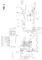
- FIG. 1 is an explanation view schematically showing a schematic configuration of a control device for an internal combustion engine according to the present invention.
- An internal combustion engine 1 is mounted, as a driving source, on a vehicle such as an automobile.
- the internal combustion engine 1 includes an intake passage 2 and an exhaust passage 3.
- the intake passage 2 is connected to the internal combustion engine 1.
- An air cleaner 4, an air flow meter 5, an electromotive first throttle valve 6, and an electromotive second throttle valve 7 are provided to the intake passage 2.
- the air cleaner 4 is arranged to collect (catch) foreign objects in the intake air.
- the air flow meter 5 is arranged to sense an intake air amount.
- the second throttle valve 7 is positioned on an upstream side of the first throttle valve 6.
- the air flow meter 5 is disposed on the upstream side of the second throttle valve 7.
- the air cleaner 4 is disposed on the upstream side of the air flow meter 5.
- the first throttle valve 6 is arranged to control the intake air amount of the internal combustion engine 1 in accordance with a load.
- the second throttle valve 7 is arranged to control an intake pressure on the upstream side of a compressor 12 (described later). That is, the second throttle valve 7 in this embodiment is arranged to control a negative pressure on the upstream side of the compressor 12 (described later).
- a passage opening area of the first throttle valve 6 at a predetermined fully closed position is set to be smaller than a passage opening area of the second throttle valve 7 at a predetermined fully closed position. That is, the passage opening area of the second throttle valve 7 at the predetermined fully closed position is set to be greater than the passage opening area of the first throttle valve 6 at the predetermined fully closed position.
- the exhaust passage 3 is connected to the internal combustion engine 1.
- An upstream side exhaust catalyst 8, a downstream side exhaust catalyst 9, an underfloor catalyst 10, and a muffler 11 are provided to the exhaust passage 3.
- the upstream side exhaust catalyst 8 is a three-way catalyst and so on.
- the downstream side exhaust catalyst 9 is a three-way catalyst and so on.
- the underfloor catalyst 10 is a three-way catalyst and so on.
- the muffler 11 is arranged to decrease the exhaust noise.
- the downstream side exhaust catalyst 9 is disposed on the downstream side of the upstream side exhaust catalyst 8, on the upstream side of the underfloor catalyst 10.
- the underfloor catalyst 10 is disposed on the downstream side of the downstream side exhaust catalyst 9.
- the muffler 11 is disposed on the downstream side of the underfloor catalyst 10.
- This internal combustion engine 1 includes a turbo supercharger 14 which is a supercharger, and which includes a compressor 12 provided to the intake passage 2, and a turbine 13 provided to the exhaust passage 3, and disposed coaxially with the compressor 12.
- the compressor 12 is positioned on the upstream side of the first throttle valve 6, on the downstream side of the second throttle valve 7.
- the turbine 13 is disposed on the upstream side of the upstream side exhaust catalyst 8.
- an intercooler 15 is provided to the intake passage 2 on the downstream side of the first throttle valve 6.
- the intercooler 15 is arranged to cool the intake air compressed by the compressor 12, and to thereby improve the charging efficiency (filling efficiency).
- the intercooler 15, a radiator 16 for the intercooler (intercooler radiator), and an electromotive pump 17 are disposed in an intercooler cooling passage (sub cooling passage) 18.
- the intercooler 15 is arranged to receive a refrigerant (cooling water) cooled by the radiator 16.
- the intercooler cooling passage 18 is arranged to circulate the refrigerant within the passage.
- the intercooler cooling passage 18 is a cooling passage independently of a main cooling passage (not shown) within which the cooling water for cooling a cylinder block 19 of the internal combustion engine 1 is circulated.
- the radiator 16 is arranged to cool the refrigerant within the intercooler cooling passage 18, by heat exchange between the refrigerant and the outside air.
- the electromotive pump 17 is arranged to be driven to circulate the refrigerant between the radiator 16 and the intercooler 15 in a direction of an arrow A.
- An exhaust bypass passage 20 is connected to the exhaust passage 3.
- the exhaust bypass passage 20 bypasses (circuits) the turbine 13.
- the exhaust bypass passage 20 connects the upstream side and the downstream side of the turbine 13.
- the exhaust bypass passage 20 includes a downstream side end connected to the exhaust passage 3 at a positon on the upstream side of the upstream side exhaust catalyst 8.
- An electromotive waste gate valve 21 is disposed to the exhaust bypass passage 20.
- the waste gate valve 21 is arranged to control an exhaust flow rate within the exhaust bypass passage 20.
- the internal combustion engine 1 is arranged to perform an exhaust gas recirculation (EGR) to introduce (recirculate), as EGR gas, part of the exhaust gas from the exhaust passage 3, to the intake passage 2.
- the internal combustion engine 1 includes an EGR passage 22 which is bifurcated from the exhaust passage 3, and connected to the intake passage 2.
- the EGR passage 22 includes one end connected to the exhaust passage 3 at a position between the downstream side exhaust catalyst 9 and the underfloor catalyst 10, and the other end connected to the intake passage 2 at a positon which is on the downstream side of the second throttle valve 7, and which is on the upstream side of the compressor 12.
- An electromotive EGR valve 23 and an EGR cooler 24 are provided to the EGR passage 22.
- the EGR valve 23 is arranged to adjust (regulate) the EGR gas flow rate within the EGR passage 22.
- the EGR cooler 24 is arranged to cool the EGR gas.
- the opening and closing operations of the first throttle valve 6, the second throttle valve 7, and the EGR valve 23 are controlled by a control unit 25 which is a control section.
- the control unit 25 is a known digital computer including a CPU, a ROM, a RAM, and an input and output interface.
- the control unit 25 is configured to receive the detection signal (detection value) of the above-described air flow meter 5. Moreover, the control unit 25 is configured to receive detection signals (detection values) of various sensors such as a crank angle sensor 31 arranged to sense a crank angle of a crank shaft (not shown), and an engine speed, an accelerator opening degree sensor 32 arranged to sense an accelerator pedal depression amount (accelerator opening degree APO) indicative of a desired load state of the internal combustion engine 1, a first throttle opening degree sensor 33 which is a first throttle valve opening degree sensing section arranged to sense a valve opening degree of the first throttle valve 6, a second throttle opening degree sensor 34 which is a second throttle valve opening degree sensing section arranged to sense a valve opening degree of the second throttle valve 7, a first pressure sensor 35 arranged to sense the intake pressure on the downstream side of the compressor 12, and a second pressure sensor 36 arranged to sense the intake pressure on the downstream side of the second throttle valve 7.
- a crank angle sensor 31 arranged to sense a crank angle of a
- the first pressure sensor 35 is arranged to sense the intake pressure which is on the upstream side of the first throttle valve 6, and which is on the downstream side of the compressor 12.
- the second pressure sensor 36 is arranged to sense the intake pressure which is on the upstream side of the compressor 12, and which is on the downstream side of the second throttle valve 7.
- control unit 25 is configured to control an ignition timing and an air fuel ratio of the internal combustion engine 1, to control to drive the electromotive pump 17, and to control the valve opening degree of the waste gate valve 21, based on the above-described detection signals (the detection values).
- a target valve opening degree of the first throttle valve 6 is calculated to attain a desired torque calculated based on the operation amount of the accelerator pedal by the driver, and so on.
- a target valve opening degree of the second throttle valve 7 is calculated at each timing based on the intake pressure necessary for the downstream side of the second throttle valve 7.
- the target valve opening degree of the second throttle valve 7 is calculated by a predetermined operational expression using this EGR introduction opening intake pressure. This calculation is repeatedly performed in a short cycle (for example, an interval of several ms to several hundred ms).
- the EGR introduction opening intake pressure is set from an opening characteristic of the first throttle valve 6, and so on.
- the target valve opening degree of the second throttle valve 7 may be obtained by referring to a previously prepared map associated with the desired torque and so on.
- the target valve opening degrees of the first throttle valve 6 and the second throttle valve 7 are calculated in the control unit 25.
- a movement in the valve closing direction from a predetermined fully closed positon is restricted by a stopper mechanism 41.
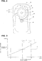
- FIG. 2 is an explanation view schematically showing an outline of the stopper mechanism 41.
- the stopper mechanism 41 includes a closing side stopper portion 47 which is a stopper portion provided to a first gear 42, and a closing side stopper piece portion 51 which is a stopper piece portion protruding from an inner wall surface of a housing 50.
- the first gear 42 is fixed to a rotation shaft 44 of a motor 43 which is a driving source for the second throttle valve 7.
- the first gear 42 includes a main body portion 45 which has a circular plate shape, and which is disposed coaxially with a rotation shaft 44; and a gear portion 46 and the closing side stopper portion 47 which are provided on an outer circumference of the main body portion 45.
- the entire gear portion 46 has an arc shape.
- the gear portion 46 is provided on a part of the outer circumference of the main body portion 45.
- the gear portion 46 includes an outer circumference including a plurality of teeth engaged with a second gear 48.
- the closing side stopper 47 is formed on a portion of the outer circumference of the main body portion 45 on which the gear portion 46 is not formed.
- the second gear 48 is fixed on a valve shaft 49 of the second throttle valve 7.
- the second gear 48 has a circular plate shape.
- the second gear 48 is disposed coaxially with the valve shaft 49.
- a plurality of teeth are formed on an overall outer circumference of the second gear 48.
- the plurality of the teeth of the second gear 48 are engaged with the teeth of the gear portion 46 of the first gear 42.
- the housing 50 receives the first gear 42, and the second gear 48 engaged with the first gear 42.
- the closing side stopper piece portion 51 is formed at a position at which the closing side stopper 47 is abutted on the closing side stopper piece portion 51 when the second throttle valve 7 is positioned at the predetermined fully closed positon.
- the closing side stopper piece portion 51 is integral with the housing 50.
- the closing side stopper piece portion 51 is arranged to restrict the rotation of the first gear 42 so that the first gear 42 is not further rotated in the closing direction when the closing side stopper portion 47 is abutted on the closing side stopper piece portion 51. That is, the stopper mechanism 41 is arranged to stop the rotation of the first gear 42 in the valve closing direction of the second throttle valve 7 when the closing side stopper portion 47 is abutted on the closing side stopper piece portion 51.
- the negative pressure is suddenly developed when the valve opening degree of the second throttle valve 7 is the closing side opening degree relative to (with respect to) the target valve opening degree due to the malfunction by the failure and so on, in a driving region in which the sufficient pressure difference is generated between the intake passage 2 and the exhaust passage 3, for example, in a high load and high rotation speed region. Accordingly, the excessive rotation of the turbo supercharger 14 and the oil leakage from a portion (for example, the oil seal portion of lubricating seal component and so on of the turbo supercharger 14) may be generated.
- a first throttle valve opening degree correction is performed by controlling the valve opening degree of the first throttle valve 6 to the opening degree on the closing side relative to the target valve opening degree of the first throttle valve.
- valve opening degree of the second throttle valve 7 is the opening degree on the closing side relative to the target valve opening degree
- the negative pressure is developed when the passage opening area of the first throttle valve 6 is greater than the passage opening area of the second throttle valve 7.
- the passage opening area of the first throttle valve 6 is controlled to be smaller than the passage opening area of the second throttle valve 7.
- the EGR valve 23 is closed to stop the EGR.
- the predetermined fully closed positon of the second throttle valve 7 which is restricted by the stopper mechanism 41 is set to, for example, a range R from an opening degree D2 to an opening degree D3 in FIG. 3 .
- a characteristic line C shown by a solid line in FIG. 3 shows a relationship between the intake pressure of the outlet of the compressor 12, and the valve opening degree of the second throttle valve 7 with respect to the valve opening degree of the first throttle valve 6 when the driving region is the high load and high rotation speed region.
- a broken line L in FIG. 3 shows pressure P by which the oil leakage may be generated from the portion (for example, the oil seal portion such as the lubrication seal components of the turbo supercharger 14) which is positioned on the downstream side of the second throttle valve 7 to seal the oil.
- the pressure P is a negative pressure limit value (negative pressure threshold value) at the oil seal portion which is positioned on the downstream side of the second throttle valve 7.
- An opening degree D1 is a valve opening degree of the second throttle valve 7 at which the engine stall is caused.
- the valve opening degree of the second throttle valve 7 becomes equal to or smaller than D1
- the engine stall is generated due to the deficiency of the air volume (amount).
- the opening degree D2 is a valve opening degree at which the characteristic line C and the broken line L are intersected.
- the opening degree D3 is a valve opening degree which is greater than the opening degree D2 by a predetermined amount, and which is set in consideration of the variation of the stopper mechanism 41.
- the passage opening area of the first throttle valve 6 at the fully closed position is set to be smaller than the passage opening area of the second throttle valve 7 at the fully closed position.
- the opening degree of the first throttle valve 6 is restricted (controlled) so as to supply a minimum air necessary for the traveling of the vehicle.
- the second throttle valve 7 is controlled so that the passage opening area of the second throttle valve 7 becomes greater than the passage opening area of the first throttle valve 6, it is surely prevent the engine stall.
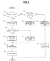
- FIG. 4 is a flowchart showing one example of a flow of the control of the internal combustion engine 1 according to this embodiment.
- step S1 it is judged whether or not an actual valve opening degree R_ADM of the second throttle valve 7 is extremely smaller than a target valve opening degree T_ADM of the second throttle valve 7.
- the process proceeds to step S2.
- step S7 the process proceeds to step S7. That is, when the actual valve opening degree R_ADM of the second throttle valve 7 is so small to be out of a predetermined variation relative to the target valve opening degree T_ADM of the second throttle valve 7, the process proceeds to step S2.
- step S7 The actual valve opening degree R_ADM of the second throttle valve 7 can be sensed by the second throttle opening degree sensor 34. Moreover, the actual valve opening degree R_ADM of the second throttle valve 7 can be calculated by using the detection signal (the detection value) of the second pressure sensor 36.
- the target valve opening degree T_THC of the first throttle valve 6 is controlled to be smaller than the actual valve opening degree R_ADM of the second throttle valve 7. That is, the control is performed so that the passage opening area of the first throttle valve 6 is smaller than the passage opening area of the second throttle valve 7.
- step S3 it is judged whether or not the target valve opening degree T_THC of the first throttle valve 6 is greater than the actual valve opening degree R_ADM of the second throttle valve 7.
- target valve opening degree T_THC of the first throttle valve 6 is greater than the actual valve opening degree R_ADM of the second throttle valve 7, the process proceeds to step S4.
- this is not satisfied the process proceeds to step S9.
- a limp home operation is performed by an output limitation of the internal combustion engine 1 to leave the output for the vehicle to be able to perform the retreat traveling (turnout travel) by itself. That is, the valve opening degree of the first throttle valve 6 is limited to an opening degree by which it is possible to obtain the output for the vehicle to be able to travel by itself.
- the EGR is set to be unexecutable. This is because the EGR cannot be controlled when the malfunction is generated in the second throttle valve 7 due to the failure and so on.
- a warning lamp is lightened.
- the warning lamp is provided at a position which can be viewed from a driver's seat, for example, an instrument panel of the driver's seat.
- the warning lamp is arranged to inform the driver that the second throttle valve 7 is in the abnormal state.
- step S7 it is judged whether or not the actual valve opening degree R_ADM of the second throttle valve 7 is smaller or greater than the target valve opening degree T_ADM of the second throttle valve 7.
- the process proceeds to step S8.
- the process proceeds to step S10.
- step S8 it is judged that the second throttle valve 7 is failed (in the failure state).
- step S9 the second throttle valve 7 is commanded (controlled) so that the valve opening degree becomes the full open.
- step S10 it is judged that the second throttle valve 7 is in the normal state.
- the EGR is set to be executable.
- an elastic member such as a return spring (not shown) may be provided so as to constantly act a force to move the valve opening degree of the second throttle valve 7 in the valve opening direction, to the first gear 42 or the second gear 48.
- an initial setting (default) of the valve opening degree of the second throttle valve 7 is full open. That is, in this case, the valve opening degree of the second throttle valve 7 is full open in a state where the control signal is not outputted to the second throttle valve 7.
- the valve opening degree of the second throttle valve 7 is full open even when the valve opening degree of the second throttle valve 7 is not controlled to be the target value by the control signal.
- the setting valve opening degree is a concept (term) including the target valve opening degree of the second throttle valve 7, and the valve opening degree of the initial setting (the default) of the second throttle valve 7.
- bypass passage (not shown) to bypass the compressor 12 may be provided to the intake passage 2.
- a recirculation valve (not shown) to recirculate the supercharged air to the bypass passage 37 may be provided to the bypass passage 37.
- the above-described embodiment relates to the control method for the internal combustion engine 1 and the control device for the internal combustion engine 1.
Abstract
Description
- This invention relates to a control method for an internal combustion engine and a control device for the internal combustion engine.
- For example, a
patent document 1 discloses an exhaust gas purification device for an internal combustion engine with a supercharger. In this exhaust gas purification device, an introduction opening for EGR gas is provided on an upstream side of a compressor. A throttle valve is disposed on the upstream side of this introduction opening. The throttle valve is arranged to adjust a mixture ratio between the flesh air and the EGR. Moreover, a control valve is disposed on a downstream side of the compressor. - In the
patent document 1, the control valve is controlled in accordance with a driving state of the engine in a manner substantially similar to the throttle valve. The control valve is controlled to be fully closed at a start and a stop. - However, the
patent document 1 does not disclose operation when the throttle valve is failed (malfunctioned). - Patent Document 1: Japanese Patent Application Publication No.
2002-106398 - In a control method of an internal combustion engine according to the present invention, a valve opening degree of a first throttle valve arranged to control an intake air amount is controller to be an opening degree on a closing side relative to a target valve opening degree when a valve opening degree of a second throttle valve arranged to control an intake pressure on an upstream side of a supercharger is an opening degree on a closing side relative to a predetermined set valve opening degree.
- By the present invention, it is possible to suppress the development of the negative pressure on the downstream side of the second throttle valve due to the malfunction by the failure of the second throttle valve, and so on.
-
-
FIG. 1 is an explanation view schematically showing a schematic configuration of a control device for an internal combustion engine according to the present invention. -
FIG. 2 is an explanation view schematically showing an outline of a stopper mechanism. -
FIG. 3 is a characteristic view showing a relationship between a valve opening degree of a second throttle valve and an intake pressure at a compressor outlet. -
FIG. 4 is a flowchart showing a flow of a control of the internal combustion engine. - Hereinafter, one embodiment according to the present invention is explained in detail with reference to the drawings.
FIG. 1 is an explanation view schematically showing a schematic configuration of a control device for an internal combustion engine according to the present invention. - An
internal combustion engine 1 is mounted, as a driving source, on a vehicle such as an automobile. Theinternal combustion engine 1 includes anintake passage 2 and anexhaust passage 3. - The
intake passage 2 is connected to theinternal combustion engine 1. Anair cleaner 4, anair flow meter 5, an electromotivefirst throttle valve 6, and an electromotivesecond throttle valve 7 are provided to theintake passage 2. Theair cleaner 4 is arranged to collect (catch) foreign objects in the intake air. Theair flow meter 5 is arranged to sense an intake air amount. Thesecond throttle valve 7 is positioned on an upstream side of thefirst throttle valve 6. - The
air flow meter 5 is disposed on the upstream side of thesecond throttle valve 7. Theair cleaner 4 is disposed on the upstream side of theair flow meter 5. Thefirst throttle valve 6 is arranged to control the intake air amount of theinternal combustion engine 1 in accordance with a load. Thesecond throttle valve 7 is arranged to control an intake pressure on the upstream side of a compressor 12 (described later). That is, thesecond throttle valve 7 in this embodiment is arranged to control a negative pressure on the upstream side of the compressor 12 (described later). - A passage opening area of the
first throttle valve 6 at a predetermined fully closed position is set to be smaller than a passage opening area of thesecond throttle valve 7 at a predetermined fully closed position. That is, the passage opening area of thesecond throttle valve 7 at the predetermined fully closed position is set to be greater than the passage opening area of thefirst throttle valve 6 at the predetermined fully closed position. - The
exhaust passage 3 is connected to theinternal combustion engine 1. An upstreamside exhaust catalyst 8, a downstreamside exhaust catalyst 9, anunderfloor catalyst 10, and amuffler 11 are provided to theexhaust passage 3. The upstreamside exhaust catalyst 8 is a three-way catalyst and so on. The downstreamside exhaust catalyst 9 is a three-way catalyst and so on. Theunderfloor catalyst 10 is a three-way catalyst and so on. Themuffler 11 is arranged to decrease the exhaust noise. - The downstream
side exhaust catalyst 9 is disposed on the downstream side of the upstreamside exhaust catalyst 8, on the upstream side of theunderfloor catalyst 10. Theunderfloor catalyst 10 is disposed on the downstream side of the downstreamside exhaust catalyst 9. Themuffler 11 is disposed on the downstream side of theunderfloor catalyst 10. - This
internal combustion engine 1 includes aturbo supercharger 14 which is a supercharger, and which includes acompressor 12 provided to theintake passage 2, and aturbine 13 provided to theexhaust passage 3, and disposed coaxially with thecompressor 12. Thecompressor 12 is positioned on the upstream side of thefirst throttle valve 6, on the downstream side of thesecond throttle valve 7. Theturbine 13 is disposed on the upstream side of the upstreamside exhaust catalyst 8. - Moreover, an
intercooler 15 is provided to theintake passage 2 on the downstream side of thefirst throttle valve 6. Theintercooler 15 is arranged to cool the intake air compressed by thecompressor 12, and to thereby improve the charging efficiency (filling efficiency). - The
intercooler 15, aradiator 16 for the intercooler (intercooler radiator), and anelectromotive pump 17 are disposed in an intercooler cooling passage (sub cooling passage) 18. Theintercooler 15 is arranged to receive a refrigerant (cooling water) cooled by theradiator 16. - The
intercooler cooling passage 18 is arranged to circulate the refrigerant within the passage. Theintercooler cooling passage 18 is a cooling passage independently of a main cooling passage (not shown) within which the cooling water for cooling acylinder block 19 of theinternal combustion engine 1 is circulated. - The
radiator 16 is arranged to cool the refrigerant within theintercooler cooling passage 18, by heat exchange between the refrigerant and the outside air. - The
electromotive pump 17 is arranged to be driven to circulate the refrigerant between theradiator 16 and theintercooler 15 in a direction of an arrow A. - An
exhaust bypass passage 20 is connected to theexhaust passage 3. Theexhaust bypass passage 20 bypasses (circuits) theturbine 13. Theexhaust bypass passage 20 connects the upstream side and the downstream side of theturbine 13. Theexhaust bypass passage 20 includes a downstream side end connected to theexhaust passage 3 at a positon on the upstream side of the upstreamside exhaust catalyst 8. An electromotivewaste gate valve 21 is disposed to theexhaust bypass passage 20. Thewaste gate valve 21 is arranged to control an exhaust flow rate within theexhaust bypass passage 20. - Moreover, the
internal combustion engine 1 is arranged to perform an exhaust gas recirculation (EGR) to introduce (recirculate), as EGR gas, part of the exhaust gas from theexhaust passage 3, to theintake passage 2. Theinternal combustion engine 1 includes anEGR passage 22 which is bifurcated from theexhaust passage 3, and connected to theintake passage 2. TheEGR passage 22 includes one end connected to theexhaust passage 3 at a position between the downstreamside exhaust catalyst 9 and theunderfloor catalyst 10, and the other end connected to theintake passage 2 at a positon which is on the downstream side of thesecond throttle valve 7, and which is on the upstream side of thecompressor 12. Anelectromotive EGR valve 23 and anEGR cooler 24 are provided to theEGR passage 22. TheEGR valve 23 is arranged to adjust (regulate) the EGR gas flow rate within theEGR passage 22. TheEGR cooler 24 is arranged to cool the EGR gas. - In this case, the opening and closing operations of the
first throttle valve 6, thesecond throttle valve 7, and theEGR valve 23 are controlled by acontrol unit 25 which is a control section. Thecontrol unit 25 is a known digital computer including a CPU, a ROM, a RAM, and an input and output interface. - The
control unit 25 is configured to receive the detection signal (detection value) of the above-describedair flow meter 5. Moreover, thecontrol unit 25 is configured to receive detection signals (detection values) of various sensors such as acrank angle sensor 31 arranged to sense a crank angle of a crank shaft (not shown), and an engine speed, an acceleratoropening degree sensor 32 arranged to sense an accelerator pedal depression amount (accelerator opening degree APO) indicative of a desired load state of theinternal combustion engine 1, a first throttleopening degree sensor 33 which is a first throttle valve opening degree sensing section arranged to sense a valve opening degree of thefirst throttle valve 6, a second throttleopening degree sensor 34 which is a second throttle valve opening degree sensing section arranged to sense a valve opening degree of thesecond throttle valve 7, afirst pressure sensor 35 arranged to sense the intake pressure on the downstream side of thecompressor 12, and asecond pressure sensor 36 arranged to sense the intake pressure on the downstream side of thesecond throttle valve 7. Thefirst pressure sensor 35 is arranged to sense the intake pressure which is on the upstream side of thefirst throttle valve 6, and which is on the downstream side of thecompressor 12. Thesecond pressure sensor 36 is arranged to sense the intake pressure which is on the upstream side of thecompressor 12, and which is on the downstream side of thesecond throttle valve 7. - Besides, the
control unit 25 is configured to control an ignition timing and an air fuel ratio of theinternal combustion engine 1, to control to drive theelectromotive pump 17, and to control the valve opening degree of thewaste gate valve 21, based on the above-described detection signals (the detection values). - For example, a target valve opening degree of the
first throttle valve 6 is calculated to attain a desired torque calculated based on the operation amount of the accelerator pedal by the driver, and so on. - For example, a target valve opening degree of the
second throttle valve 7 is calculated at each timing based on the intake pressure necessary for the downstream side of thesecond throttle valve 7. - In a driving condition in which a predetermined amount of the EGR gas is introduced into the
intake passage 2, it is necessary to set an EGR introduction opening intake pressure which is the intake pressure (negative pressure) that is on the downstream side of thesecond throttle valve 7 so that the target EGR gas amount can be introduced into theintake passage 2. Accordingly, the target valve opening degree of thesecond throttle valve 7 is calculated by a predetermined operational expression using this EGR introduction opening intake pressure. This calculation is repeatedly performed in a short cycle (for example, an interval of several ms to several hundred ms). The EGR introduction opening intake pressure is set from an opening characteristic of thefirst throttle valve 6, and so on. The target valve opening degree of thesecond throttle valve 7 may be obtained by referring to a previously prepared map associated with the desired torque and so on. - The target valve opening degrees of the
first throttle valve 6 and thesecond throttle valve 7 are calculated in thecontrol unit 25. - In this embodiment, in the valve opening degree of the
second throttle valve 7, a movement in the valve closing direction from a predetermined fully closed positon is restricted by astopper mechanism 41. -
FIG. 2 is an explanation view schematically showing an outline of thestopper mechanism 41. Thestopper mechanism 41 includes a closingside stopper portion 47 which is a stopper portion provided to afirst gear 42, and a closing sidestopper piece portion 51 which is a stopper piece portion protruding from an inner wall surface of ahousing 50. - The
first gear 42 is fixed to arotation shaft 44 of amotor 43 which is a driving source for thesecond throttle valve 7. Thefirst gear 42 includes amain body portion 45 which has a circular plate shape, and which is disposed coaxially with arotation shaft 44; and agear portion 46 and the closingside stopper portion 47 which are provided on an outer circumference of themain body portion 45. - The
entire gear portion 46 has an arc shape. Thegear portion 46 is provided on a part of the outer circumference of themain body portion 45. Thegear portion 46 includes an outer circumference including a plurality of teeth engaged with asecond gear 48. - The
closing side stopper 47 is formed on a portion of the outer circumference of themain body portion 45 on which thegear portion 46 is not formed. - The
second gear 48 is fixed on avalve shaft 49 of thesecond throttle valve 7. Thesecond gear 48 has a circular plate shape. Thesecond gear 48 is disposed coaxially with thevalve shaft 49. A plurality of teeth are formed on an overall outer circumference of thesecond gear 48. The plurality of the teeth of thesecond gear 48 are engaged with the teeth of thegear portion 46 of thefirst gear 42. - The
housing 50 receives thefirst gear 42, and thesecond gear 48 engaged with thefirst gear 42. - The closing side
stopper piece portion 51 is formed at a position at which theclosing side stopper 47 is abutted on the closing sidestopper piece portion 51 when thesecond throttle valve 7 is positioned at the predetermined fully closed positon. - The closing side
stopper piece portion 51 is integral with thehousing 50. The closing sidestopper piece portion 51 is arranged to restrict the rotation of thefirst gear 42 so that thefirst gear 42 is not further rotated in the closing direction when the closingside stopper portion 47 is abutted on the closing sidestopper piece portion 51. That is, thestopper mechanism 41 is arranged to stop the rotation of thefirst gear 42 in the valve closing direction of thesecond throttle valve 7 when the closingside stopper portion 47 is abutted on the closing sidestopper piece portion 51. That is, when the closingside stopper portion 47 is abutted on the closing sidestopper piece portion 51, the rotation of thesecond gear 48 is stopped, so as to stop the rotation of thevalve shaft 49 of thesecond throttle valve 7 which is arranged to rotate as a unit with thesecond gear 48. - In the above-described embodiment, it is possible to control the negative pressure on the downstream side of the
second throttle valve 7 by controlling thesecond throttle valve 7. Accordingly, it is possible to introduce the EGR gas into theintake passage 2 even in a driving region in which a pressure difference between theintake passage 2 and theexhaust passage 3 is small, for example, in a low load and low rotation speed region. - However, the negative pressure is suddenly developed when the valve opening degree of the
second throttle valve 7 is the closing side opening degree relative to (with respect to) the target valve opening degree due to the malfunction by the failure and so on, in a driving region in which the sufficient pressure difference is generated between theintake passage 2 and theexhaust passage 3, for example, in a high load and high rotation speed region. Accordingly, the excessive rotation of theturbo supercharger 14 and the oil leakage from a portion (for example, the oil seal portion of lubricating seal component and so on of the turbo supercharger 14) may be generated. - Accordingly, in this embodiment, when the valve opening degree of the
second throttle valve 7 is the closing side opening degree relative to the target valve opening degree of thesecond throttle valve 7, a first throttle valve opening degree correction is performed by controlling the valve opening degree of thefirst throttle valve 6 to the opening degree on the closing side relative to the target valve opening degree of the first throttle valve. - With this, it is possible to suppress the excessive development of the negative pressure on the downstream side of the
second throttle valve 7 at the malfunction due to the failure of thesecond throttle valve 7, and so on. - Therefore, it is possible to suppress the excessive rotation of the turbo supercharger 14 (the compressor 12) positioned on the downstream side of the
second throttle valve 7, and to suppress the oil leakage from the oil seal portion which is located on the downstream side of thesecond throttle valve 7. - In a case where the valve opening degree of the
second throttle valve 7 is the opening degree on the closing side relative to the target valve opening degree, the negative pressure is developed when the passage opening area of thefirst throttle valve 6 is greater than the passage opening area of thesecond throttle valve 7. - Accordingly, when the first throttle valve opening degree correction is performed, the passage opening area of the
first throttle valve 6 is controlled to be smaller than the passage opening area of thesecond throttle valve 7. - With this, it is possible to suppress the development of the negative pressure, to improve the reliability of the function at the malfunction due to the failure and so on of the
second throttle valve 7, and to perform the secure and reliable failsafe. - Moreover, when the first throttle valve opening degree correction is performed, the
EGR valve 23 is closed to stop the EGR. - With this, it is possible to avoid the engine stall generated by the excessive flow of the EGR gas into the
intake passage 2. - Moreover, in the above-described embodiment, the predetermined fully closed positon of the
second throttle valve 7 which is restricted by thestopper mechanism 41 is set to, for example, a range R from an opening degree D2 to an opening degree D3 inFIG. 3 . - A characteristic line C shown by a solid line in
FIG. 3 shows a relationship between the intake pressure of the outlet of thecompressor 12, and the valve opening degree of thesecond throttle valve 7 with respect to the valve opening degree of thefirst throttle valve 6 when the driving region is the high load and high rotation speed region. A broken line L inFIG. 3 shows pressure P by which the oil leakage may be generated from the portion (for example, the oil seal portion such as the lubrication seal components of the turbo supercharger 14) which is positioned on the downstream side of thesecond throttle valve 7 to seal the oil. When the intake pressure of the outlet of thecompressor 12 is smaller than this pressure P, that is, when the negative pressure smaller than the pressure P is developed, the oil leakage is generated due to the influence of the negative pressure. That is, the pressure P is a negative pressure limit value (negative pressure threshold value) at the oil seal portion which is positioned on the downstream side of thesecond throttle valve 7. - An opening degree D1 is a valve opening degree of the
second throttle valve 7 at which the engine stall is caused. When the valve opening degree of thesecond throttle valve 7 becomes equal to or smaller than D1, the engine stall is generated due to the deficiency of the air volume (amount). - The opening degree D2 is a valve opening degree at which the characteristic line C and the broken line L are intersected.
- The opening degree D3 is a valve opening degree which is greater than the opening degree D2 by a predetermined amount, and which is set in consideration of the variation of the
stopper mechanism 41. - By setting the fully closed position of the
second throttle valve 7 by thestopper mechanism 41, even when the malfunction of thesecond throttle valve 7 is generated due to the failure and so on, it is possible to surely avoid the engine stall due to the deficiency of the air volume, and the oil leakage on the downstream side of thesecond throttle valve 7 due to the development of the excessive negative pressure. - Moreover, the passage opening area of the
first throttle valve 6 at the fully closed position is set to be smaller than the passage opening area of thesecond throttle valve 7 at the fully closed position. - With this, even when the valve opening degree of the
second throttle valve 7 becomes the fully closed position due to the malfunction by the failure and so on, it is possible to decrease the passage opening area of thefirst throttle valve 6 to be smaller than the passage opening area of thesecond throttle valve 7, by decreasing the valve opening degree of thefirst throttle valve 6. Accordingly, it is possible to suppress the development of the negative pressure, to improve the function reliability at the malfunction by the failure and so on of thesecond throttle valve 7, and to attain the secure and sure failsafe. - Furthermore, at the failure of the
first throttle valve 6, the opening degree of thefirst throttle valve 6 is restricted (controlled) so as to supply a minimum air necessary for the traveling of the vehicle. At this time, in a case where thesecond throttle valve 7 is controlled so that the passage opening area of thesecond throttle valve 7 becomes greater than the passage opening area of thefirst throttle valve 6, it is surely prevent the engine stall. -
FIG. 4 is a flowchart showing one example of a flow of the control of theinternal combustion engine 1 according to this embodiment. - At step S1, it is judged whether or not an actual valve opening degree R_ADM of the
second throttle valve 7 is extremely smaller than a target valve opening degree T_ADM of thesecond throttle valve 7. When the actual valve opening degree R_ADM is extremely smaller than the target valve opening degree T_ADM, the process proceeds to step S2. When this is not satisfied, the process proceeds to step S7. That is, when the actual valve opening degree R_ADM of thesecond throttle valve 7 is so small to be out of a predetermined variation relative to the target valve opening degree T_ADM of thesecond throttle valve 7, the process proceeds to step S2. When this is not satisfied, the process proceeds to step S7. The actual valve opening degree R_ADM of thesecond throttle valve 7 can be sensed by the second throttleopening degree sensor 34. Moreover, the actual valve opening degree R_ADM of thesecond throttle valve 7 can be calculated by using the detection signal (the detection value) of thesecond pressure sensor 36. - At step S2, the target valve opening degree T_THC of the
first throttle valve 6 is controlled to be smaller than the actual valve opening degree R_ADM of thesecond throttle valve 7. That is, the control is performed so that the passage opening area of thefirst throttle valve 6 is smaller than the passage opening area of thesecond throttle valve 7. - At step S3, it is judged whether or not the target valve opening degree T_THC of the
first throttle valve 6 is greater than the actual valve opening degree R_ADM of thesecond throttle valve 7. When target valve opening degree T_THC of thefirst throttle valve 6 is greater than the actual valve opening degree R_ADM of thesecond throttle valve 7, the process proceeds to step S4. When this is not satisfied, the process proceeds to step S9. - At step S4, a limp home operation is performed by an output limitation of the
internal combustion engine 1 to leave the output for the vehicle to be able to perform the retreat traveling (turnout travel) by itself. That is, the valve opening degree of thefirst throttle valve 6 is limited to an opening degree by which it is possible to obtain the output for the vehicle to be able to travel by itself. - At step S5, the EGR is set to be unexecutable. This is because the EGR cannot be controlled when the malfunction is generated in the
second throttle valve 7 due to the failure and so on. - At step S6, a warning lamp (MIL) is lightened. The warning lamp is provided at a position which can be viewed from a driver's seat, for example, an instrument panel of the driver's seat. The warning lamp is arranged to inform the driver that the
second throttle valve 7 is in the abnormal state. - At step S7, it is judged whether or not the actual valve opening degree R_ADM of the
second throttle valve 7 is smaller or greater than the target valve opening degree T_ADM of thesecond throttle valve 7. When the actual valve opening degree R_ADM of thesecond throttle valve 7 is deviated from the target valve opening degree T_ADM of thesecond throttle valve 7, the process proceeds to step S8. When this is not satisfied, the process proceeds to step S10. - At step S8, it is judged that the
second throttle valve 7 is failed (in the failure state). - At step S9, the
second throttle valve 7 is commanded (controlled) so that the valve opening degree becomes the full open. - At step S10, it is judged that the
second throttle valve 7 is in the normal state. - At step S11, the EGR is set to be executable.
- Besides, in the above-described embodiment, an elastic member such as a return spring (not shown) may be provided so as to constantly act a force to move the valve opening degree of the
second throttle valve 7 in the valve opening direction, to thefirst gear 42 or thesecond gear 48. - In a case where the
second throttle valve 7 is constantly urged in the valve opening direction by the above-described elastic member, an initial setting (default) of the valve opening degree of thesecond throttle valve 7 is full open. That is, in this case, the valve opening degree of thesecond throttle valve 7 is full open in a state where the control signal is not outputted to thesecond throttle valve 7. - Accordingly, in a case where the initial setting (the default) of the valve opening degree of the
second throttle valve 7 is full open, when the exhaust pressure is sufficiently high by the high speed or the high load and so on of theinternal combustion engine 1, or when the EGR is not performed, the valve opening degree of thesecond throttle valve 7 is full open even when the valve opening degree of thesecond throttle valve 7 is not controlled to be the target value by the control signal. - Therefore, for example, when the initial setting (the default) of the valve opening degree of the
second throttle valve 7 is the full open, it is judged whether or not the valve opening degree of thesecond throttle valve 7 is the closing side relative to the predetermined setting valve opening degree. It is judged that the valve opening degree of thesecond throttle valve 7 is the opening degree on the closing side relative to the setting valve opening degree, the valve opening degree of thefirst throttle valve 6 is corrected to the opening degree on the closing side relative to the target valve opening degree. In this case, the setting valve opening degree is a concept (term) including the target valve opening degree of thesecond throttle valve 7, and the valve opening degree of the initial setting (the default) of thesecond throttle valve 7. - Moreover, a bypass passage (not shown) to bypass the
compressor 12 may be provided to theintake passage 2. Moreover, a recirculation valve (not shown) to recirculate the supercharged air to the bypass passage 37 may be provided to the bypass passage 37. - The above-described embodiment relates to the control method for the
internal combustion engine 1 and the control device for theinternal combustion engine 1.
Claims (7)
- A control method for an internal combustion engine including
a supercharger positioned on an upstream side of a first throttle valve arranged to control an intake air amount,
a second throttle valve positioned on the upstream side of the supercharger, and arranged to control an intake pressure on the upstream side of the supercharger,
an EGR passage arranged to recirculate a part of an exhaust gas to a portion between the supercharger and the second throttle valve, and
an EGR valve arranged to adjust an EGR gas flow rate flowing in the EGR passage,
the control method comprising:setting a target valve opening degree of the first throttle valve in accordance with a load,sensing a valve opening degree of the second throttle valve,judging whether or not the valve opening degree of the second throttle valve is an opening degree on a closing side relative to a predetermined set valve opening degree, andcorrecting the valve opening degree of the first throttle valve to the opening degree on the closing side relative to the target valve opening degree when it is judged that the valve opening degree of the second throttle valve is the opening degree on the closing side relative to the predetermined set valve opening degree. - The control method for the internal combustion engine as claimed in claim 1, wherein when the valve opening degree of the first throttle valve is corrected to the opening degree on the closing side relative to the target valve opening degree, a passage opening area of the first throttle valve is controlled to be smaller than a passage opening area of the second throttle valve.
- The control method for the internal combustion engine as claimed in claim 1 or 2, wherein there is provided a stopper mechanism arranged to restrict a movement of the second throttle valve from a fully closed position in a closing direction; and the passage opening area of the first throttle valve in a fully closed position is set to be smaller than a passage opening area of the second throttle valve in the fully closing positon.
- The control method for the internal combustion engine as claimed in one of claims 1 to 3, wherein a passage opening area of the second throttle valve in a fully closing positon is set to be equal to or smaller than a negative pressure limit of an oil seal portion positioned on a downstream side of the second throttle valve.
- The control method for the internal combustion engine as claimed in one of claims 1 to 4, wherein the passage opening area of the second throttle valve is controlled to be greater than the passage opening area of the first throttle valve, at a malfunction of the first throttle valve.
- The control method for the internal combustion engine as claimed in one of claims 1 to 5, wherein when the valve opening degree of the first throttle valve is corrected to the opening degree on the closing side relative to the target valve opening degree, the EGR is closed to stop the EGR.
- A control device for an internal combustion engine, the control device comprising:a first throttle valve arranged to control an intake air amount of the internal combustion engine in accordance with a load;a supercharger positioned on an upstream side of the first throttle valve;a second throttle valve positioned on an upstream side of the first throttle valve;an EGR passage arranged to recirculate a part of an exhaust gas to a portion between the supercharger and the second throttle valve;an EGR valve arranged to adjust an EGR gas flow amount flowing in the EGR passage;a second throttle valve opening degree sensing section arranged to sense a valve opening degree of the second throttle valve; anda control section configured to control a valve opening degree of the first throttle valve to the valve opening degree on the closing side relative to a valve opening degree determined in accordance with the load, when it is judged that the valve opening degree of the second throttle valve is the opening degree on the closing side relative to a predetermined set valve opening degree.
Applications Claiming Priority (1)
| Application Number | Priority Date | Filing Date | Title |
|---|---|---|---|
| PCT/JP2017/001172 WO2018131152A1 (en) | 2017-01-16 | 2017-01-16 | Method for controlling internal combustion engine and device for controlling internal combustion engine |
Publications (3)
| Publication Number | Publication Date |
|---|---|
| EP3569847A1 true EP3569847A1 (en) | 2019-11-20 |
| EP3569847A4 EP3569847A4 (en) | 2019-12-25 |
| EP3569847B1 EP3569847B1 (en) | 2024-02-07 |
Family
ID=62840459
Family Applications (1)
| Application Number | Title | Priority Date | Filing Date |
|---|---|---|---|
| EP17890873.7A Active EP3569847B1 (en) | 2017-01-16 | 2017-01-16 | Method for controlling internal combustion engine and device for controlling internal combustion engine |
Country Status (9)
| Country | Link |
|---|---|
| US (1) | US10890126B2 (en) |
| EP (1) | EP3569847B1 (en) |
| JP (1) | JP6743914B2 (en) |
| CN (1) | CN110168209B (en) |
| BR (1) | BR112019014490A2 (en) |
| MX (1) | MX2019007993A (en) |
| MY (1) | MY197166A (en) |
| RU (1) | RU2721070C1 (en) |
| WO (1) | WO2018131152A1 (en) |
Cited By (1)
| Publication number | Priority date | Publication date | Assignee | Title |
|---|---|---|---|---|
| EP3656993A1 (en) * | 2018-11-21 | 2020-05-27 | Volkswagen Aktiengesellschaft | Method for diagnosing a loaded combustion engine in terms of a leakage in a section of the fresh gas section |
Families Citing this family (6)
| Publication number | Priority date | Publication date | Assignee | Title |
|---|---|---|---|---|
| JP6749297B2 (en) * | 2017-08-24 | 2020-09-02 | 日立オートモティブシステムズ株式会社 | Internal combustion engine controller |
| US10823120B2 (en) * | 2018-11-16 | 2020-11-03 | Fca Us Llc | Spark ignited engine load extension with low pressure exhaust gas recirculation and delta pressure valve |
| CN111255581B (en) * | 2020-02-22 | 2021-03-23 | 东风汽车集团有限公司 | Control system and method for electronic throttle valve of exhaust gas turbocharged engine |
| CN115244282B (en) * | 2020-03-02 | 2024-03-08 | 日产自动车株式会社 | Abnormality diagnosis method for internal combustion engine and abnormality diagnosis device for internal combustion engine |
| US11313291B2 (en) * | 2020-08-03 | 2022-04-26 | GM Global Technology Operations LLC | Secondary throttle control systems and methods |
| CN112901377B (en) * | 2021-02-10 | 2022-04-01 | 东风汽车集团股份有限公司 | Method for determining activation state of mixing valve of low-pressure EGR system |
Family Cites Families (14)
| Publication number | Priority date | Publication date | Assignee | Title |
|---|---|---|---|---|
| DE4141169A1 (en) * | 1991-12-13 | 1993-06-17 | Josef Lenz | Boost control for injection engine - has two connected throttle valves, one in front of supercharger, moving synchronously in opening or closing directions to control air feed to supercharger |
| JP3791318B2 (en) | 2000-10-02 | 2006-06-28 | トヨタ自動車株式会社 | Exhaust gas purification device for an internal combustion engine with a supercharger |
| JP4192763B2 (en) * | 2003-11-07 | 2008-12-10 | 株式会社日立製作所 | Electronic EGR gas control device |
| JP4677920B2 (en) | 2006-02-10 | 2011-04-27 | トヨタ自動車株式会社 | Internal combustion engine and control device for internal combustion engine |
| JP4215069B2 (en) * | 2006-04-26 | 2009-01-28 | トヨタ自動車株式会社 | Exhaust gas recirculation device for internal combustion engine |
| JP2008248729A (en) * | 2007-03-29 | 2008-10-16 | Honda Motor Co Ltd | Egr control device for internal combustion engine |
| JP2010242640A (en) * | 2009-04-07 | 2010-10-28 | Toyota Motor Corp | Intake air leakage detection system for internal combustion engine |
| FR2945076A3 (en) * | 2009-04-29 | 2010-11-05 | Renault Sas | Device for supercharging diesel engine, has proportional control valve arranged on upstream intake conduit to regulate flow of intake, and turbine driven by exhaust gas circulating from engine to turbine via upstream exhaust conduit |
| ITBO20090702A1 (en) * | 2009-10-28 | 2011-04-28 | Magneti Marelli Spa | MIXER DEVICE FOR A LOW-PRESSURE ENGINE EGR SYSTEM WITH INTERNAL COMBUSTION |
| JP5287953B2 (en) * | 2011-04-27 | 2013-09-11 | 株式会社デンソー | Low pressure EGR device |
| JP5825994B2 (en) * | 2011-11-25 | 2015-12-02 | 日立オートモティブシステムズ株式会社 | Control device for internal combustion engine |
| CN104053888B (en) * | 2012-01-11 | 2016-07-06 | 丰田自动车株式会社 | The control device of internal combustion engine |
| JP6028925B2 (en) * | 2013-03-01 | 2016-11-24 | 三菱自動車工業株式会社 | Control device for internal combustion engine |
| US9341127B2 (en) * | 2014-06-06 | 2016-05-17 | Ford Global Technologies, Llc | Multivariable low-pressure exhaust gas recirculation control |
-
2017
- 2017-01-16 CN CN201780082703.5A patent/CN110168209B/en active Active
- 2017-01-16 WO PCT/JP2017/001172 patent/WO2018131152A1/en unknown
- 2017-01-16 EP EP17890873.7A patent/EP3569847B1/en active Active
- 2017-01-16 BR BR112019014490-0A patent/BR112019014490A2/en unknown
- 2017-01-16 MX MX2019007993A patent/MX2019007993A/en unknown
- 2017-01-16 RU RU2019124197A patent/RU2721070C1/en active
- 2017-01-16 MY MYPI2019003808A patent/MY197166A/en unknown
- 2017-01-16 US US16/476,946 patent/US10890126B2/en active Active
- 2017-01-16 JP JP2018561765A patent/JP6743914B2/en active Active
Cited By (1)
| Publication number | Priority date | Publication date | Assignee | Title |
|---|---|---|---|---|
| EP3656993A1 (en) * | 2018-11-21 | 2020-05-27 | Volkswagen Aktiengesellschaft | Method for diagnosing a loaded combustion engine in terms of a leakage in a section of the fresh gas section |
Also Published As
| Publication number | Publication date |
|---|---|
| US10890126B2 (en) | 2021-01-12 |
| JP6743914B2 (en) | 2020-08-19 |
| JPWO2018131152A1 (en) | 2019-11-07 |
| CN110168209B (en) | 2022-03-04 |
| MX2019007993A (en) | 2019-09-06 |
| CN110168209A (en) | 2019-08-23 |
| EP3569847B1 (en) | 2024-02-07 |
| BR112019014490A2 (en) | 2020-02-11 |
| EP3569847A4 (en) | 2019-12-25 |
| US20190353109A1 (en) | 2019-11-21 |
| MY197166A (en) | 2023-05-27 |
| WO2018131152A1 (en) | 2018-07-19 |
| RU2721070C1 (en) | 2020-05-15 |
Similar Documents
| Publication | Publication Date | Title |
|---|---|---|
| US10890126B2 (en) | Method for controlling internal combustion engine and device for controlling internal combustion engine | |
| US9709009B2 (en) | Low pressure exhaust gas recirculation apparatus | |
| US9145841B2 (en) | Low-pressure exhaust gas recirculation system | |
| US8156925B2 (en) | Exhaust gas recirculation system for internal combustion engine | |
| US8924123B2 (en) | Internal combustion engine boost pressure diagnostic apparatus | |
| EP2952729B1 (en) | Exhaust gas recirculation control device and exhaust gas recirculation control method for an internal combustion engine | |
| US20080047525A1 (en) | Method of diagnosing electrically driven supercharger | |
| US10683797B2 (en) | Waste gate valve control method and control device | |
| CN114207259B (en) | Leakage diagnosis method and leakage diagnosis device for leakage treatment device of internal combustion engine | |
| MXPA02008550A (en) | Intelligent electric actuator for control of a turbocharger with an integrated exhaust gas recirculation valve. | |
| US10513971B2 (en) | Valve control device | |
| US10982604B2 (en) | Gasoline engine system with improved idle up control upon detecting abnormality in valve during deceleration | |
| US20180266341A1 (en) | Control device of internal-combustion engine | |
| US20150240704A1 (en) | Supercharging apparatus for engine | |
| CN114207401B (en) | Leakage diagnosis method and leakage diagnosis device for leakage treatment device of internal combustion engine | |
| US20170363025A1 (en) | Control apparatus for internal combustion engine | |
| US8229654B2 (en) | Device for limiting output of internal combustion engine when the engine has abnormality | |
| KR20180066660A (en) | Method and apparatus for diagnosing engine system | |
| JP2632368B2 (en) | Method for judging abnormality of internal combustion engine with supercharger | |
| EP4116548B1 (en) | Abnormality diagnostic method for internal combustion engine and abnormality diagnostic device for internal combustion engine | |
| JP2017040223A (en) | Egr control device for engine |
Legal Events
| Date | Code | Title | Description |
|---|---|---|---|
| STAA | Information on the status of an ep patent application or granted ep patent |
Free format text: STATUS: THE INTERNATIONAL PUBLICATION HAS BEEN MADE |
|
| PUAI | Public reference made under article 153(3) epc to a published international application that has entered the european phase |
Free format text: ORIGINAL CODE: 0009012 |
|
| STAA | Information on the status of an ep patent application or granted ep patent |
Free format text: STATUS: REQUEST FOR EXAMINATION WAS MADE |
|
| 17P | Request for examination filed |
Effective date: 20190731 |
|
| AK | Designated contracting states |
Kind code of ref document: A1 Designated state(s): AL AT BE BG CH CY CZ DE DK EE ES FI FR GB GR HR HU IE IS IT LI LT LU LV MC MK MT NL NO PL PT RO RS SE SI SK SM TR |
|
| AX | Request for extension of the european patent |
Extension state: BA ME |
|
| A4 | Supplementary search report drawn up and despatched |
Effective date: 20191127 |
|
| RIC1 | Information provided on ipc code assigned before grant |
Ipc: F02M 26/06 20160101ALI20191121BHEP Ipc: F02D 41/22 20060101ALI20191121BHEP Ipc: F02D 9/02 20060101AFI20191121BHEP Ipc: F02M 26/10 20160101ALI20191121BHEP Ipc: F02D 11/10 20060101ALI20191121BHEP Ipc: F02D 41/00 20060101ALI20191121BHEP |
|
| DAV | Request for validation of the european patent (deleted) | ||
| DAX | Request for extension of the european patent (deleted) | ||
| STAA | Information on the status of an ep patent application or granted ep patent |
Free format text: STATUS: EXAMINATION IS IN PROGRESS |
|
| 17Q | First examination report despatched |
Effective date: 20220120 |
|
| RAP3 | Party data changed (applicant data changed or rights of an application transferred) |
Owner name: RENAULT S.A.S Owner name: NISSAN MOTOR CO., LTD. |
|
| RAP3 | Party data changed (applicant data changed or rights of an application transferred) |
Owner name: RENAULT S.A.S Owner name: NISSAN MOTOR CO., LTD. |
|
| GRAP | Despatch of communication of intention to grant a patent |
Free format text: ORIGINAL CODE: EPIDOSNIGR1 |
|
| STAA | Information on the status of an ep patent application or granted ep patent |
Free format text: STATUS: GRANT OF PATENT IS INTENDED |
|
| GRAS | Grant fee paid |
Free format text: ORIGINAL CODE: EPIDOSNIGR3 |
|
| INTG | Intention to grant announced |
Effective date: 20231204 |
|
| GRAA | (expected) grant |
Free format text: ORIGINAL CODE: 0009210 |
|
| STAA | Information on the status of an ep patent application or granted ep patent |
Free format text: STATUS: THE PATENT HAS BEEN GRANTED |
|
| RAP1 | Party data changed (applicant data changed or rights of an application transferred) |
Owner name: NEW H POWERTRAIN HOLDING, S.L.U. Owner name: NISSAN MOTOR CO., LTD. |
|
| AK | Designated contracting states |
Kind code of ref document: B1 Designated state(s): AL AT BE BG CH CY CZ DE DK EE ES FI FR GB GR HR HU IE IS IT LI LT LU LV MC MK MT NL NO PL PT RO RS SE SI SK SM TR |
|
| REG | Reference to a national code |
Ref country code: GB Ref legal event code: FG4D |
|
| REG | Reference to a national code |
Ref country code: CH Ref legal event code: EP |
|
| REG | Reference to a national code |
Ref country code: DE Ref legal event code: R096 Ref document number: 602017079058 Country of ref document: DE |
|
| REG | Reference to a national code |
Ref country code: IE Ref legal event code: FG4D |