EP3569845B1 - Hybrides elektrisches gebläse mit abwürgefreiem niederdruckverdichter - Google Patents
Hybrides elektrisches gebläse mit abwürgefreiem niederdruckverdichter Download PDFInfo
- Publication number
- EP3569845B1 EP3569845B1 EP19174692.4A EP19174692A EP3569845B1 EP 3569845 B1 EP3569845 B1 EP 3569845B1 EP 19174692 A EP19174692 A EP 19174692A EP 3569845 B1 EP3569845 B1 EP 3569845B1
- Authority
- EP
- European Patent Office
- Prior art keywords
- electric motor
- fan
- geared architecture
- section
- speed
- Prior art date
- Legal status (The legal status is an assumption and is not a legal conclusion. Google has not performed a legal analysis and makes no representation as to the accuracy of the status listed.)
- Active
Links
Images


Classifications
-
- F—MECHANICAL ENGINEERING; LIGHTING; HEATING; WEAPONS; BLASTING
- F02—COMBUSTION ENGINES; HOT-GAS OR COMBUSTION-PRODUCT ENGINE PLANTS
- F02K—JET-PROPULSION PLANTS
- F02K5/00—Plants including an engine, other than a gas turbine, driving a compressor or a ducted fan
-
- F—MECHANICAL ENGINEERING; LIGHTING; HEATING; WEAPONS; BLASTING
- F02—COMBUSTION ENGINES; HOT-GAS OR COMBUSTION-PRODUCT ENGINE PLANTS
- F02C—GAS-TURBINE PLANTS; AIR INTAKES FOR JET-PROPULSION PLANTS; CONTROLLING FUEL SUPPLY IN AIR-BREATHING JET-PROPULSION PLANTS
- F02C6/00—Plural gas-turbine plants; Combinations of gas-turbine plants with other apparatus; Adaptations of gas-turbine plants for special use
-
- F—MECHANICAL ENGINEERING; LIGHTING; HEATING; WEAPONS; BLASTING
- F02—COMBUSTION ENGINES; HOT-GAS OR COMBUSTION-PRODUCT ENGINE PLANTS
- F02C—GAS-TURBINE PLANTS; AIR INTAKES FOR JET-PROPULSION PLANTS; CONTROLLING FUEL SUPPLY IN AIR-BREATHING JET-PROPULSION PLANTS
- F02C7/00—Features, components parts, details or accessories, not provided for in, or of interest apart form groups F02C1/00 - F02C6/00; Air intakes for jet-propulsion plants
- F02C7/36—Power transmission arrangements between the different shafts of the gas turbine plant, or between the gas-turbine plant and the power user
-
- F—MECHANICAL ENGINEERING; LIGHTING; HEATING; WEAPONS; BLASTING
- F02—COMBUSTION ENGINES; HOT-GAS OR COMBUSTION-PRODUCT ENGINE PLANTS
- F02C—GAS-TURBINE PLANTS; AIR INTAKES FOR JET-PROPULSION PLANTS; CONTROLLING FUEL SUPPLY IN AIR-BREATHING JET-PROPULSION PLANTS
- F02C9/00—Controlling gas-turbine plants; Controlling fuel supply in air- breathing jet-propulsion plants
-
- F—MECHANICAL ENGINEERING; LIGHTING; HEATING; WEAPONS; BLASTING
- F02—COMBUSTION ENGINES; HOT-GAS OR COMBUSTION-PRODUCT ENGINE PLANTS
- F02K—JET-PROPULSION PLANTS
- F02K3/00—Plants including a gas turbine driving a compressor or a ducted fan
- F02K3/02—Plants including a gas turbine driving a compressor or a ducted fan in which part of the working fluid by-passes the turbine and combustion chamber
- F02K3/04—Plants including a gas turbine driving a compressor or a ducted fan in which part of the working fluid by-passes the turbine and combustion chamber the plant including ducted fans, i.e. fans with high volume, low pressure outputs, for augmenting the jet thrust, e.g. of double-flow type
- F02K3/06—Plants including a gas turbine driving a compressor or a ducted fan in which part of the working fluid by-passes the turbine and combustion chamber the plant including ducted fans, i.e. fans with high volume, low pressure outputs, for augmenting the jet thrust, e.g. of double-flow type with front fan
-
- F—MECHANICAL ENGINEERING; LIGHTING; HEATING; WEAPONS; BLASTING
- F16—ENGINEERING ELEMENTS AND UNITS; GENERAL MEASURES FOR PRODUCING AND MAINTAINING EFFECTIVE FUNCTIONING OF MACHINES OR INSTALLATIONS; THERMAL INSULATION IN GENERAL
- F16H—GEARING
- F16H1/00—Toothed gearings for conveying rotary motion
- F16H1/28—Toothed gearings for conveying rotary motion with gears having orbital motion
-
- H—ELECTRICITY
- H02—GENERATION; CONVERSION OR DISTRIBUTION OF ELECTRIC POWER
- H02K—DYNAMO-ELECTRIC MACHINES
- H02K7/00—Arrangements for handling mechanical energy structurally associated with dynamo-electric machines, e.g. structural association with mechanical driving motors or auxiliary dynamo-electric machines
- H02K7/10—Structural association with clutches, brakes, gears, pulleys or mechanical starters
- H02K7/116—Structural association with clutches, brakes, gears, pulleys or mechanical starters with gears
-
- H—ELECTRICITY
- H02—GENERATION; CONVERSION OR DISTRIBUTION OF ELECTRIC POWER
- H02K—DYNAMO-ELECTRIC MACHINES
- H02K7/00—Arrangements for handling mechanical energy structurally associated with dynamo-electric machines, e.g. structural association with mechanical driving motors or auxiliary dynamo-electric machines
- H02K7/14—Structural association with mechanical loads, e.g. with hand-held machine tools or fans
-
- H—ELECTRICITY
- H02—GENERATION; CONVERSION OR DISTRIBUTION OF ELECTRIC POWER
- H02K—DYNAMO-ELECTRIC MACHINES
- H02K7/00—Arrangements for handling mechanical energy structurally associated with dynamo-electric machines, e.g. structural association with mechanical driving motors or auxiliary dynamo-electric machines
- H02K7/18—Structural association of electric generators with mechanical driving motors, e.g. with turbines
- H02K7/1807—Rotary generators
- H02K7/1823—Rotary generators structurally associated with turbines or similar engines
-
- F—MECHANICAL ENGINEERING; LIGHTING; HEATING; WEAPONS; BLASTING
- F05—INDEXING SCHEMES RELATING TO ENGINES OR PUMPS IN VARIOUS SUBCLASSES OF CLASSES F01-F04
- F05D—INDEXING SCHEME FOR ASPECTS RELATING TO NON-POSITIVE-DISPLACEMENT MACHINES OR ENGINES, GAS-TURBINES OR JET-PROPULSION PLANTS
- F05D2220/00—Application
- F05D2220/30—Application in turbines
- F05D2220/32—Application in turbines in gas turbines
- F05D2220/323—Application in turbines in gas turbines for aircraft propulsion, e.g. jet engines
-
- F—MECHANICAL ENGINEERING; LIGHTING; HEATING; WEAPONS; BLASTING
- F05—INDEXING SCHEMES RELATING TO ENGINES OR PUMPS IN VARIOUS SUBCLASSES OF CLASSES F01-F04
- F05D—INDEXING SCHEME FOR ASPECTS RELATING TO NON-POSITIVE-DISPLACEMENT MACHINES OR ENGINES, GAS-TURBINES OR JET-PROPULSION PLANTS
- F05D2220/00—Application
- F05D2220/70—Application in combination with
-
- F—MECHANICAL ENGINEERING; LIGHTING; HEATING; WEAPONS; BLASTING
- F05—INDEXING SCHEMES RELATING TO ENGINES OR PUMPS IN VARIOUS SUBCLASSES OF CLASSES F01-F04
- F05D—INDEXING SCHEME FOR ASPECTS RELATING TO NON-POSITIVE-DISPLACEMENT MACHINES OR ENGINES, GAS-TURBINES OR JET-PROPULSION PLANTS
- F05D2260/00—Function
- F05D2260/40—Transmission of power
- F05D2260/403—Transmission of power through the shape of the drive components
- F05D2260/4031—Transmission of power through the shape of the drive components as in toothed gearing
- F05D2260/40311—Transmission of power through the shape of the drive components as in toothed gearing of the epicyclical, planetary or differential type
-
- F—MECHANICAL ENGINEERING; LIGHTING; HEATING; WEAPONS; BLASTING
- F05—INDEXING SCHEMES RELATING TO ENGINES OR PUMPS IN VARIOUS SUBCLASSES OF CLASSES F01-F04
- F05D—INDEXING SCHEME FOR ASPECTS RELATING TO NON-POSITIVE-DISPLACEMENT MACHINES OR ENGINES, GAS-TURBINES OR JET-PROPULSION PLANTS
- F05D2270/00—Control
- F05D2270/01—Purpose of the control system
- F05D2270/02—Purpose of the control system to control rotational speed (n)
-
- F—MECHANICAL ENGINEERING; LIGHTING; HEATING; WEAPONS; BLASTING
- F05—INDEXING SCHEMES RELATING TO ENGINES OR PUMPS IN VARIOUS SUBCLASSES OF CLASSES F01-F04
- F05D—INDEXING SCHEME FOR ASPECTS RELATING TO NON-POSITIVE-DISPLACEMENT MACHINES OR ENGINES, GAS-TURBINES OR JET-PROPULSION PLANTS
- F05D2270/00—Control
- F05D2270/01—Purpose of the control system
- F05D2270/05—Purpose of the control system to affect the output of the engine
- F05D2270/051—Thrust
-
- F—MECHANICAL ENGINEERING; LIGHTING; HEATING; WEAPONS; BLASTING
- F05—INDEXING SCHEMES RELATING TO ENGINES OR PUMPS IN VARIOUS SUBCLASSES OF CLASSES F01-F04
- F05D—INDEXING SCHEME FOR ASPECTS RELATING TO NON-POSITIVE-DISPLACEMENT MACHINES OR ENGINES, GAS-TURBINES OR JET-PROPULSION PLANTS
- F05D2270/00—Control
- F05D2270/01—Purpose of the control system
- F05D2270/10—Purpose of the control system to cope with, or avoid, compressor flow instabilities
- F05D2270/101—Compressor surge or stall
-
- F—MECHANICAL ENGINEERING; LIGHTING; HEATING; WEAPONS; BLASTING
- F05—INDEXING SCHEMES RELATING TO ENGINES OR PUMPS IN VARIOUS SUBCLASSES OF CLASSES F01-F04
- F05D—INDEXING SCHEME FOR ASPECTS RELATING TO NON-POSITIVE-DISPLACEMENT MACHINES OR ENGINES, GAS-TURBINES OR JET-PROPULSION PLANTS
- F05D2270/00—Control
- F05D2270/01—Purpose of the control system
- F05D2270/20—Purpose of the control system to optimize the performance of a machine
Definitions
- a gas turbine engine typically includes a fan section, a compressor section, a combustor section and a turbine section. Air entering the compressor section is compressed and delivered into the combustion section where it is mixed with fuel and ignited to generate a high-energy exhaust gas flow. The high-energy exhaust gas flow expands through the turbine section to drive the compressor and the fan section.
- the compressor section typically includes low and high pressure compressors, and the turbine section includes low and high pressure turbines.
- the fan section typically provides a majority of propulsive thrust for the engine. Adjusting a speed of the fan to provide more efficient operation requires adjustment of a speed of the drive turbine.
- a geared architecture between the fan and the drive turbine enables both to operate closer to optimal speeds.
- the drive turbine and fan are still mechanically linked and therefore any changes in speed to adjust fan speed also changes the speed of the drive turbine.
- the drive turbine typically drives a low pressure compressor. Changing speeds of the low pressure compressor can complicate operation and place constraints on the speed of the fan.
- US 2004/255590 A1 discloses a prior art differential geared turbine engine with torque modulation capability.
- US 2014/290265 A1 discloses a prior art gas turbine engine having a differential transmission.
- a first clutch assembly is disposed between the first electric motor and the geared architecture and a second clutch assembly disposed between the second electric motor and the geared architecture, wherein the first clutch assembly enables input from the first electric motor in only the first direction and the second clutch assembly enables input from the second electric motor in only the second direction.
- the driven gear is coupled to the carrier.
- the driven gear is coupled to the ring gear.
- a compressor in another embodiment of any of the foregoing gas turbine engines, includes a section with a low pressure compressor and the turbine section includes a low pressure turbine that drives both the low pressure compressor and the geared architecture.
- the low pressure compressor is driven by the low pressure turbine at a speed different then the fan section.
- the first electric motor assembly drives the fan in the first direction to increase fan speed.
- the second electric motor assembly is configured such that rotation of the geared architecture enables a speed of the fan to remain constant with a change in speed of the second driving input provided by the turbine section.
- the first electric motor assembly and the second electric motor assembly operate to maintain a rotational speed of the fan blades while decreasing a speed of a low pressure compressor driven by the turbine section.
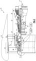
- FIG. 1 schematically illustrates a gas turbine engine 20.
- the gas turbine engine 20 is disclosed herein as a two-spool turbofan that generally incorporates a fan section 22, a compressor section 24, a combustor section 26 and a turbine section 28.
- the fan section 22 drives air along a bypass flow path B in a bypass duct defined within a nacelle 18, and also drives air along a core flow path C for compression and communication into the combustor section 26 then expansion through the turbine section 28.
- FIG. 1 schematic
- the low speed spool 30 generally includes an inner shaft 40 that interconnects, a first (or low) pressure compressor 44 and a first (or low) pressure turbine 46.
- the inner shaft 40 is connected to the fan section 22 through a speed change mechanism, which in the exemplary gas turbine engine 20 is illustrated as a geared architecture 48 to drive fan blades 42 at a lower speed than the low speed spool 30.
- the high speed spool 32 includes an outer shaft 50 that interconnects a second (or high) pressure compressor 52 and a second (or high) pressure turbine 54.
- a combustor 56 is arranged in the exemplary gas turbine 20 between the high pressure compressor 52 and the high pressure turbine 54.
- the geared architecture 48 may be an epicycle gear train, such as a planetary gear system or other gear system, with a gear reduction ratio of greater than 2.3:1 and less than 5:1. It should be understood, however, that the above parameters are only exemplary of one embodiment of a geared architecture engine.
- the "Low corrected fan tip speed” as disclosed herein according to one non-limiting embodiment is less than 1150 ft / second (350.5 meters/second).
- the example gas turbine engine includes the fan section 22 that comprises in one non-limiting embodiment less than twenty-six fan blades 42. In another non-limiting embodiment, the fan section 22 includes less than twenty fan blades 42. Moreover, in one disclosed embodiment the low pressure turbine 46 includes no more than six turbine rotors schematically indicated at 34. In another non-limiting example embodiment the low pressure turbine 46 includes three turbine rotors. A ratio between the number of fan blades 42 and the number of low pressure turbine rotors is between 3.3 and 8.6. The example low pressure turbine 46 provides the driving power to rotate the fan section 22 and therefore the relationship between the number of turbine rotors 34 in the low pressure turbine 46 and the number of blades 42 in the fan section 22 disclose an example gas turbine engine 20 with increased power transfer efficiency.
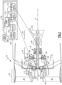
- the example gas turbine engine 20 includes a first electric motor assembly 72 that is coupled to drive the fan section 22.
- a second electric motor assembly 74 is coupled to drive the geared architecture 48 relative to the static structure 36 of the engine 20.
- the first and second electric motor assemblies 72, 74 enable the fan blades 42 to rotate about the axis A at a speed different than provided by the geared architecture 48.
- Changes to propulsive thrust provided by the fan section 22 require a corresponding change of speed of the low pressure turbine 46.
- the low pressure turbine 46 also drives the low pressure compressor 44 and results in changes in speed of the low pressure compressor 44.
- Increasing the speed of the low pressure compressor 44 may result in the compressor rotating at speeds that do not provide efficient operation or that provide pressures and flows that are not within desired ranges for efficient operation of the high pressure compressor 52.
- Performance of the low-pressure compressor 44 is matched to the operation of the high-pressure compressor 52 to provide the most efficient use of energy and provide optimal engine operating conditions. Inputting additional power by increasing the speed of the low-pressure compressor 44 may disrupt the matched performance between the low-pressure compressor 44 and the high-pressure compressor 52.
- the example gas turbine engine 20 includes the first electric motor assembly 72 that boosts a speed of rotation of the fan blades 42 about the axis A to a speed greater than that provided by the output of the geared architecture 48.
- the geared architecture 48 is driven relative to the static structure 36 of the engine by the second electric motor assembly 74.
- the geared architecture 48 is not structurally grounded directly to the static engine structure 36 but is instead mechanically grounded to the engine static 36 structure through the electric motor assembly 74. It should be understood that various bearing systems 38 at various locations may alternatively or additionally be provided, and the location of bearing systems 38 may be varied as appropriate to the application.
- the electric motor assembly 74 rotates the geared architecture 48 to partially decouple fan speed from a speed provided by the low pressure turbine 46 through the geared architecture 48.
- the example gas turbine engine 20 is shown schematically and includes the first electric motor assembly 72 that is disposed on a fan shaft 70 that supports the plurality of fan blades 42.
- the first motor assembly 72 provides a first drive input for driving the fan blades 42 about the axis and is operated by a motor control 104 that is a part of a motor controller 100.
- the example motor controller 100 can receive information from an engine control such as in this example a Full Authority Digital Electronic Control (FADEC) 98.
- the electric motor 72 inputs power directly to the fan shaft 70 to provide a boost of power directly to the fan section 22.
- the increased power provided by the electric motor 72 enables a boost to the speed of the fan section 22 independent of the low pressure turbine 46.
- the geared architecture 48 provides a second drive input to drive the fan blades 42 about the axis A.
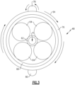
- the second electric motor assembly 74 includes a first electric motor 82 and a second electric motor 84 that are both coupled to drive a driven gear 76 that is attached to a carrier 68.
- the example geared architecture 48 includes a sun gear 62 driven by the shaft 40. The sun gear 62 in turns drives intermediate gears 64 that are supported on the carrier 68. The intermediate gears 68 are circumscribed by a ring gear 66. The ring gear 66 is coupled to drive the fan shaft 70.
- the driven gear 76 is a single gear that is attached to the carrier 68 and is coupled to a first drive gear 78 and second drive gear 80.
- the disclosed gear architecture 48 is not directly coupled to the engine static structure 36 but is instead rotatable about the axis A independent of rotation of the shaft 40.
- the first electric motor 82 includes a first clutch 86.
- the electric motor 82 drives the first shaft 88 that drives the first drive gear 78 that is coupled to the driven gear 76.
- the driven gear 76 is a gear that is disposed about the axis A and rotates the geared architecture 48. It should be understood that various bearing systems 38 at various locations may alternatively or additionally be provided, and the location of bearing systems 38 may be varied as appropriate to the application.
- the first clutch assembly 86 is a one way clutch such that the electric motor 82 may only drive the first shaft 88 in the first direction.
- the second electric motor 84 and the second clutch 90 enables the second electric motor 84 to drive the shaft 92 in a second direction.
- the second clutch 90 decouples the second electric motor 84 such that no driving input is provided by the second electric motor 84.
- the sun gear 62 rotates counterclockwise.
- FIG. 4 another example operational condition is illustrated where the second electric motor 84 is driving the second gear 80 in a second counterclockwise direction 96.
- the geared architecture 48 is rotated in a counterclockwise direction and provides for a reduction in fan speed relative to the input provided by the low pressure turbine 46.
- the reduction in the fan speed is independent of the input speed provided by the low pressure turbine 46. Accordingly the fan speed 42 is decoupled from the input provided by the low pressure turbine 46 and the geared architecture 48.
- neither the first electric motor 82 nor the second electric motor 84 is operational thereby locking the geared architecture in a fixed position.
- the low pressure turbine 46 drives the geared architecture 48 and thereby the fan section 22 at a constant speed dictated by the structure and gear ratio of the geared architecture 48.
- the first electric motor assembly 72 is not operated and the engine operates with the fan blades 42 turning at a speed that corresponds with the low pressure turbine 46 and the gear ratio provided by the gear architecture 48.
- the first electric motor assembly 72 provides a boost to fan shaft 70 speed of rotation of the fan blades 42 about the axis A to a speed greater than that provided by the output of the geared architecture 48.
- the first electric motor assembly 72 that is coupled to drive the fan section 22 is a motor.
- the assembly 72 may comprise of a motor-generator that provides a load to fan shaft 70 speed of rotation of the fan blades 42 about the axis A to a speed smaller than that provided by the output of the geared architecture 48.
- first electric motor 82 and the second electric motor 84 are each illustrated as a single electric motor.
- each of the first electric motor and second electric motor 82, 84 may comprise several electric motors that are each engaged to the driven gear 76 to provide rotation of the geared architecture relative of the engine static structure in either the first direction 94 or the second direction 96.
Landscapes
- Engineering & Computer Science (AREA)
- Chemical & Material Sciences (AREA)
- Combustion & Propulsion (AREA)
- General Engineering & Computer Science (AREA)
- Mechanical Engineering (AREA)
- Power Engineering (AREA)
- Structures Of Non-Positive Displacement Pumps (AREA)
Claims (11)
- Gasturbinentriebwerk (20, 25), umfassend:einen Fan-Abschnitt (22), der eine Vielzahl von Fan-Blättern (42) umfasst, wobei eine erste Elektromotoranordnung (72) mit einer Fan-Welle (70) gekoppelt ist und einen ersten Antriebseingang zum Antreiben der Fan-Blätter (42) um eine Achse (A) bereitstellt;eine Steuerung (100), die den Betrieb der ersten Elektromotoranordnung (72) steuert;einen Turbinenabschnitt (28);eine Zahnradarchitektur (48), die von dem Turbinenabschnitt (28) angetrieben und mit dem Fan-Abschnitt (22) gekoppelt ist, um einen zweiten Antriebseingang zum Antreiben der Fan-Blätter (42) bereitzustellen, wobei die Getriebearchitektur (48) ein Sonnenrad (62) umfasst, das eine Vielzahl von Zwischenrädern (64) antreibt, die von einem Hohlrad (66) umschlossen wird, wobei ein Träger (68) die Vielzahl von Zwischenrädern (64) stützt;ein angetriebenes Zahnrad (76), das mit der Zahnradarchitektur (48) gekoppelt ist; undeine zweite Elektromotoranordnung (74), die mit dem angetriebenen Zahnrad (76) gekoppelt ist, um die Zahnradarchitektur (48) relativ zu einer festen Struktur (36) gemäß Befehl der Steuerung (100) zu drehen, um eine Drehzahl der Fan-Blätter (42) zu steuern, die durch eine Kombination aus dem ersten Antriebseingang und dem zweiten Antriebseingang bereitgestellt wird, wobei die zweite Elektromotoranordnung (74) einen ersten Elektromotor (82) zum Drehen der Zahnradarchitektur (48) in eine erste Richtung und einen zweiten Elektromotor (84) zum Drehen der Zahnradarchitektur (48) in eine zweite Richtung umfasst, wobei eine Drehung der Zahnradarchitektur (48) in die erste Richtung eine Erhöhung einer Drehzahl des Fan-Abschnitts (22) ermöglicht und eine Drehung in die zweite Richtung eine Verringerung einer Drehzahl des Fan-Abschnitts (22) ohne eine Änderung der Drehzahl des vom Turbinenabschnitt (28) bereitgestellten zweiten Antriebseingangs ermöglicht.
- Gasturbinentriebwerk (20, 25) nach Anspruch 1, beinhaltend eine erste Kupplungsanordnung (86), die zwischen dem ersten Elektromotor (82) und der Zahnradarchitektur (48) angeordnet ist, und eine zweite Kupplungsanordnung (90), die zwischen dem zweiten Elektromotor (84) und der Zahnradarchitektur (48) angeordnet ist, wobei die erste Kupplungsanordnung (86) eine Eingabe von dem ersten Elektromotor (82) nur in der ersten Richtung ermöglicht und die zweite Kupplungsanordnung (90) eine Eingabe von dem zweiten Elektromotor (84) nur in der zweiten Richtung ermöglicht.
- Gasturbinentriebwerk (20, 25) nach Anspruch 1 oder 2, wobei das angetriebene Zahnrad (76) von einem ersten Antriebszahnrad (78), das von dem ersten Elektromotor (82) angetrieben wird, oder von einem zweiten Antriebszahnrad (80), das von dem zweiten Elektromotor (84) angetrieben wird, angetrieben wird.
- Gasturbinentriebwerk (20, 25) nach einem der vorhergehenden Ansprüche, wobei das angetriebene Zahnrad (76) mit dem Träger (68) oder dem Hohlrad (66) gekoppelt ist.
- Gasturbinentriebwerk (20, 25) nach einem der vorhergehenden Ansprüche, wobei der Fan-Abschnitt (22) eine Fan-Welle (70) beinhaltet, die an das Hohlrad (66) gekoppelt ist, oder wobei der Fan-Abschnitt (22) eine Fan-Welle (70) beinhaltet, die an den Träger (68) gekoppelt ist.
- Gasturbinentriebwerk (20, 25) nach einem der vorhergehenden Ansprüche, wobei die erste Elektromotoranordnung (72) den Fan-Abschnitt (22) in der ersten Richtung antreibt, um die Fan-Drehzahl zu erhöhen.
- Gasturbinentriebwerk (20, 25) nach einem der vorhergehenden Ansprüche, wobei die zweite Elektromotoranordnung (74) dazu konfiguriert ist, dass eine Drehung der Zahnradarchitektur (48) es ermöglicht, dass eine Drehzahl des Fan-Abschnitts (22) bei einer Drehzahländerung der vom Turbinenabschnitt (28) bereitgestellten zweiten Antriebseingabe konstant bleibt.
- Gasturbinentriebwerk (20, 25) nach einem der vorhergehenden Ansprüche, beinhaltend einen Verdichterabschnitt (24), der einen Niederdruckverdichter (44) umfasst, wobei der Turbinenabschnitt (28) eine Niederdruckturbine (46) beinhaltet, die sowohl den Niederdruckverdichter (44) als auch die Zahnradarchitektur (48) antreibt, wobei optional der Niederdruckverdichter (44) durch die Niederdruckturbine (46) mit einer anderen Drehzahl als der Fan-Abschnitt (22) angetrieben wird.
- Verfahren zum Betreiben eines Gasturbinentriebwerks (20, 25), umfassend:Koppeln einer ersten Elektromotoranordnung (72) an eine Fan-Welle (70) eines Fan-Abschnitts (22), um einen ersten Antriebseingang zum Antreiben der Fan-Blätter (42) bereitzustellen;Koppeln einer Zahnradarchitektur (48), die von einem Turbinenabschnitt (28) des Triebwerks angetrieben wird, an den Fan-Abschnitt (22), um einen zweiten Antriebseingang zum Antreiben der Fan-Blätter (42) bereitzustellen, wobei die Getriebearchitektur (48) ein Sonnenrad (62) umfasst, das eine Vielzahl von Zwischenrädern (64) antreibt, die von einem Hohlrad (66) umschlossen wird, wobei ein Träger (68) die Vielzahl von Zwischenrädern (64) stützt;Koppeln eines angetriebenen Zahnrads (76) an die Zahnradarchitektur (48);Koppeln einer zweiten Elektromotoranordnung (74) an das angetriebene Zahnrad (76), um die Zahnradarchitektur (48) relativ zu einer statischen Triebwerksstruktur (36) zu drehen; undSteuern der ersten Elektromotoranordnung (72) und der zweiten Elektromotoranordnung (74), um eine Kombination aus der ersten Antriebseingabe und der zweiten Antriebseingabe bereitzustellen, um die Fan-Blätter (42) mit einer vordefinierten Drehgeschwindigkeit zu drehen, wobei das Antreiben der Zahnradarchitektur (48) in einer ersten Richtung eine Drehgeschwindigkeit der Fan-Blätter (42) erhöht und das Antreiben der Zahnradarchitektur (48) in einer zweiten Richtung eine Drehgeschwindigkeit der Fan-Blätter (42) verringert, ohne dass sich die Drehzahl des Turbinenabschnitts (28) ändert, der die Zahnradarchitektur (48) antreibt, wobei die zweite Elektromotoranordnung (74) einen ersten Elektromotor (82) und einen zweiten Elektromotor (84) umfasst, die an das angetriebene Zahnrad (76) gekoppelt sind, und das Antreiben der Zahnradarchitektur (48) in der ersten Richtung mit dem ersten Elektromotor (82) die Drehgeschwindigkeit der Fan-Blätter (42) erhöht und das Antreiben der Zahnradarchitektur (48) in der zweiten Richtung mit dem zweiten Elektromotor (84) die Drehgeschwindigkeit der Fan-Blätter (42) verringert.
- Verfahren nach Anspruch 9, beinhaltend Koppeln einer ersten Kupplungsanordnung (86) zwischen dem ersten Elektromotor (82) und dem angetriebenen Zahnrad (76) und Koppeln einer zweiten Kupplungsanordnung (90) zwischen dem zweiten Elektromotor (84) und dem angetriebenen Zahnrad (76), sodass sowohl der erste Elektromotor (82) als auch der zweite Elektromotor (84) die Zahnradarchitektur (48) nur in einer einzigen Richtung antreiben.
- Verfahren nach Anspruch 10, beinhaltend Betreiben der ersten Elektromotoranordnung (72) und der zweiten Elektromotoranordnung (74), um eine Drehgeschwindigkeit der Fan-Blätter (42) aufrechtzuerhalten, während eine Drehzahl eines Niederdruckkompressors (44), der durch den Turbinenabschnitt (28) angetrieben wird, verringert wird.
Applications Claiming Priority (1)
| Application Number | Priority Date | Filing Date | Title |
|---|---|---|---|
| US15/980,870 US11168616B2 (en) | 2018-05-16 | 2018-05-16 | Hybrid electric fan with improved low pressure compressor |
Publications (2)
| Publication Number | Publication Date |
|---|---|
| EP3569845A1 EP3569845A1 (de) | 2019-11-20 |
| EP3569845B1 true EP3569845B1 (de) | 2025-06-25 |
Family
ID=66770155
Family Applications (1)
| Application Number | Title | Priority Date | Filing Date |
|---|---|---|---|
| EP19174692.4A Active EP3569845B1 (de) | 2018-05-16 | 2019-05-15 | Hybrides elektrisches gebläse mit abwürgefreiem niederdruckverdichter |
Country Status (2)
| Country | Link |
|---|---|
| US (2) | US11168616B2 (de) |
| EP (1) | EP3569845B1 (de) |
Families Citing this family (21)
| Publication number | Priority date | Publication date | Assignee | Title |
|---|---|---|---|---|
| US10718271B2 (en) * | 2018-05-29 | 2020-07-21 | Raytheon Technologies Corporation | Hybrid amplification of high spool motoring via low spool power extraction and motoring of a differential geared generator |
| FR3087421B1 (fr) * | 2018-10-17 | 2022-03-04 | Voltaero | Engin comprenant un groupe motopropulseur hybride et procede de pilotage correspondant |
| FR3087820B1 (fr) * | 2018-10-26 | 2020-10-16 | Safran Aircraft Engines | Turbomachine d'aeronef equipee d'une machine electrique |
| US20200158213A1 (en) * | 2018-11-21 | 2020-05-21 | United Technologies Corporation | Hybrid electric propulsion with superposition gearbox |
| GB2589676B (en) * | 2019-08-12 | 2022-10-12 | Raytheon Tech Corp | Aircraft engine power-assist start stability control |
| US11428171B2 (en) * | 2019-12-06 | 2022-08-30 | General Electric Company | Electric machine assistance for multi-spool turbomachine operation and control |
| US11519289B2 (en) | 2019-12-06 | 2022-12-06 | Raytheon Technologies Corporation | Systems and methods for hybrid electric turbine engines |
| FR3106176B1 (fr) | 2020-01-09 | 2022-02-04 | Safran Trans Systems | Réducteur pour turbomachine muni d’un générateur électrique |
| US11073107B1 (en) | 2020-01-24 | 2021-07-27 | Raytheon Technologies Corporation | Systems and methods for hybrid electric turbine engines |
| CN113958538A (zh) * | 2021-10-22 | 2022-01-21 | 清华大学 | 一种空间轮系静子叶片调节装置及涡轮发动机 |
| EP4283106B1 (de) * | 2022-05-26 | 2025-11-12 | RTX Corporation | Selektive leistungsverteilung für ein flugzeugantriebssystem |
| US12480449B2 (en) | 2022-08-22 | 2025-11-25 | General Electric Company | Propulsion system including an electric machine for starting a gas turbine engine |
| US20240247593A1 (en) * | 2023-01-25 | 2024-07-25 | Raytheon Technologies Corporation | Two piece hollow-vane assembly joined via brazing |
| US12428986B2 (en) * | 2023-07-03 | 2025-09-30 | Rtx Corporation | Aircraft propulsion system engine with multiple independent rotating structures |
| KR20260045795A (ko) * | 2023-08-08 | 2026-04-03 | 테네시 테크놀로지컬 유니버시티 | 항공기 연료전지 터보전기 팬 |
| US12188551B1 (en) | 2023-09-29 | 2025-01-07 | Rtx Corporation | Reduced clearance interface between a fluid device and a rotating structure for a geartrain |
| US12331683B2 (en) | 2023-09-29 | 2025-06-17 | Rtx Corporation | Bearing arrangement for turbine engine geartrain |
| US12135076B1 (en) | 2023-09-29 | 2024-11-05 | Rtx Corporation | Fluid device(s) for supporting rotating structure(s) of a turbine engine |
| US12292107B2 (en) | 2023-09-29 | 2025-05-06 | Rtx Corporation | Fluid damper for turbine engine geartrain assembly |
| US12187444B1 (en) * | 2024-02-06 | 2025-01-07 | Pratt & Whitney Canada Corp. | Hybrid aircraft power plant |
| EP4628716A1 (de) | 2024-04-03 | 2025-10-08 | Hamilton Sundstrand Corporation | Mehrwellen-energieübertragungssystem |
Citations (1)
| Publication number | Priority date | Publication date | Assignee | Title |
|---|---|---|---|---|
| US20140290265A1 (en) * | 2013-01-30 | 2014-10-02 | Pratt & Whitney Canada Corp. | Gas turbine engine with transmission |
Family Cites Families (8)
| Publication number | Priority date | Publication date | Assignee | Title |
|---|---|---|---|---|
| GB1484898A (en) * | 1974-09-11 | 1977-09-08 | Rolls Royce | Ducted fan gas turbine engine |
| US6895741B2 (en) * | 2003-06-23 | 2005-05-24 | Pratt & Whitney Canada Corp. | Differential geared turbine engine with torque modulation capability |
| GB0809336D0 (en) * | 2008-05-23 | 2008-07-02 | Rolls Royce Plc | A gas turbine engine arrangement |
| GB0903423D0 (en) | 2009-03-02 | 2009-04-08 | Rolls Royce Plc | Variable drive gas turbine engine |
| US8425372B2 (en) * | 2010-07-14 | 2013-04-23 | Hamilton Sundstrand Corporation | Geared turbofan emergency power |
| US10358982B2 (en) | 2013-07-07 | 2019-07-23 | United Technologies Corporation | Fan drive gear system mechanical controller |
| US10774741B2 (en) * | 2016-01-26 | 2020-09-15 | General Electric Company | Hybrid propulsion system for a gas turbine engine including a fuel cell |
| CN107178426B (zh) | 2017-06-07 | 2019-04-26 | 南昌航空大学 | 一种蓄功调速齿轮传动涡轮发动机 |
-
2018
- 2018-05-16 US US15/980,870 patent/US11168616B2/en active Active
-
2019
- 2019-05-15 EP EP19174692.4A patent/EP3569845B1/de active Active
-
2021
- 2021-10-04 US US17/493,002 patent/US11952947B2/en active Active
Patent Citations (1)
| Publication number | Priority date | Publication date | Assignee | Title |
|---|---|---|---|---|
| US20140290265A1 (en) * | 2013-01-30 | 2014-10-02 | Pratt & Whitney Canada Corp. | Gas turbine engine with transmission |
Also Published As
| Publication number | Publication date |
|---|---|
| EP3569845A1 (de) | 2019-11-20 |
| US20190353104A1 (en) | 2019-11-21 |
| US11952947B2 (en) | 2024-04-09 |
| US20220025823A1 (en) | 2022-01-27 |
| US11168616B2 (en) | 2021-11-09 |
Similar Documents
| Publication | Publication Date | Title |
|---|---|---|
| EP3569845B1 (de) | Hybrides elektrisches gebläse mit abwürgefreiem niederdruckverdichter | |
| US12571352B2 (en) | Electric enhanced transmission for multi-spool load-sharing turbofan engine | |
| EP3748146B1 (de) | Hybrides turbogebläse mit differentieller elektrischer und mechanischer leistungsübertragung | |
| EP3656997B1 (de) | Hybrider elektroantrieb mit überlagerungsgetriebe | |
| US11143111B2 (en) | Fan drive gear system mechanical controller | |
| EP3039276B1 (de) | Drei-wellen-getriebeturbolüfter mit niederdruckverdichterantriebssystem und mechanischer steuerung | |
| US20230212985A1 (en) | Differential geared amplification of auxiliary power unit | |
| EP2820249B1 (de) | Gasturbinenmotor mit einem am lüfter befestigten induktorabschnitt und mehreren niederdruckturbinenabschnitten | |
| EP3351766B1 (de) | Hochentwickelter getriebegasturbinenmotor | |
| EP3628847B1 (de) | Drehmomentarmer motorstart mit doppelter wellenleistungsentnahme mit überlagerungsgetriebe | |
| EP4215737B1 (de) | Doppelspulenleistungsextraktion mit überlagerungsgetriebe | |
| EP3636898B1 (de) | Zusatzgetriebe mit überlagerungsgetriebe | |
| EP3633152B1 (de) | Fantriebwerk mit motorisierter rotierender einlassleitschaufel | |
| EP3546737A1 (de) | Kompressoranordnung für einen gasturbinenmotor | |
| EP4686822A1 (de) | Gasturbinenmotor mit kontrollierter rückführung von kraftstoff zum antrieb von zubehörteilen und nachrüstungsverfahren | |
| US12553380B2 (en) | Constant speed accessory gearbox for turbine engine |
Legal Events
| Date | Code | Title | Description |
|---|---|---|---|
| PUAI | Public reference made under article 153(3) epc to a published international application that has entered the european phase |
Free format text: ORIGINAL CODE: 0009012 |
|
| STAA | Information on the status of an ep patent application or granted ep patent |
Free format text: STATUS: THE APPLICATION HAS BEEN PUBLISHED |
|
| AK | Designated contracting states |
Kind code of ref document: A1 Designated state(s): AL AT BE BG CH CY CZ DE DK EE ES FI FR GB GR HR HU IE IS IT LI LT LU LV MC MK MT NL NO PL PT RO RS SE SI SK SM TR |
|
| AX | Request for extension of the european patent |
Extension state: BA ME |
|
| STAA | Information on the status of an ep patent application or granted ep patent |
Free format text: STATUS: REQUEST FOR EXAMINATION WAS MADE |
|
| 17P | Request for examination filed |
Effective date: 20200522 |
|
| RBV | Designated contracting states (corrected) |
Designated state(s): AL AT BE BG CH CY CZ DE DK EE ES FI FR GB GR HR HU IE IS IT LI LT LU LV MC MK MT NL NO PL PT RO RS SE SI SK SM TR |
|
| RAP1 | Party data changed (applicant data changed or rights of an application transferred) |
Owner name: RAYTHEON TECHNOLOGIES CORPORATION |
|
| STAA | Information on the status of an ep patent application or granted ep patent |
Free format text: STATUS: EXAMINATION IS IN PROGRESS |
|
| 17Q | First examination report despatched |
Effective date: 20211213 |
|
| RAP3 | Party data changed (applicant data changed or rights of an application transferred) |
Owner name: RTX CORPORATION |
|
| GRAP | Despatch of communication of intention to grant a patent |
Free format text: ORIGINAL CODE: EPIDOSNIGR1 |
|
| STAA | Information on the status of an ep patent application or granted ep patent |
Free format text: STATUS: GRANT OF PATENT IS INTENDED |
|
| RIC1 | Information provided on ipc code assigned before grant |
Ipc: B64D 27/02 20060101ALI20231222BHEP Ipc: F02K 5/00 20060101ALI20231222BHEP Ipc: F02C 7/36 20060101AFI20231222BHEP |
|
| INTG | Intention to grant announced |
Effective date: 20240124 |
|
| GRAJ | Information related to disapproval of communication of intention to grant by the applicant or resumption of examination proceedings by the epo deleted |
Free format text: ORIGINAL CODE: EPIDOSDIGR1 |
|
| STAA | Information on the status of an ep patent application or granted ep patent |
Free format text: STATUS: EXAMINATION IS IN PROGRESS |
|
| INTC | Intention to grant announced (deleted) | ||
| GRAP | Despatch of communication of intention to grant a patent |
Free format text: ORIGINAL CODE: EPIDOSNIGR1 |
|
| STAA | Information on the status of an ep patent application or granted ep patent |
Free format text: STATUS: GRANT OF PATENT IS INTENDED |
|
| INTG | Intention to grant announced |
Effective date: 20240711 |
|
| GRAJ | Information related to disapproval of communication of intention to grant by the applicant or resumption of examination proceedings by the epo deleted |
Free format text: ORIGINAL CODE: EPIDOSDIGR1 |
|
| STAA | Information on the status of an ep patent application or granted ep patent |
Free format text: STATUS: EXAMINATION IS IN PROGRESS |
|
| INTC | Intention to grant announced (deleted) | ||
| GRAP | Despatch of communication of intention to grant a patent |
Free format text: ORIGINAL CODE: EPIDOSNIGR1 |
|
| STAA | Information on the status of an ep patent application or granted ep patent |
Free format text: STATUS: GRANT OF PATENT IS INTENDED |
|
| INTG | Intention to grant announced |
Effective date: 20250114 |
|
| GRAS | Grant fee paid |
Free format text: ORIGINAL CODE: EPIDOSNIGR3 |
|
| GRAA | (expected) grant |
Free format text: ORIGINAL CODE: 0009210 |
|
| STAA | Information on the status of an ep patent application or granted ep patent |
Free format text: STATUS: THE PATENT HAS BEEN GRANTED |
|
| AK | Designated contracting states |
Kind code of ref document: B1 Designated state(s): AL AT BE BG CH CY CZ DE DK EE ES FI FR GB GR HR HU IE IS IT LI LT LU LV MC MK MT NL NO PL PT RO RS SE SI SK SM TR |
|
| REG | Reference to a national code |
Ref country code: GB Ref legal event code: FG4D |
|
| REG | Reference to a national code |
Ref country code: CH Ref legal event code: EP |
|
| REG | Reference to a national code |
Ref country code: DE Ref legal event code: R096 Ref document number: 602019071459 Country of ref document: DE |
|
| REG | Reference to a national code |
Ref country code: CH Ref legal event code: EP |
|
| REG | Reference to a national code |
Ref country code: IE Ref legal event code: FG4D |
|
| PG25 | Lapsed in a contracting state [announced via postgrant information from national office to epo] |
Ref country code: FI Free format text: LAPSE BECAUSE OF FAILURE TO SUBMIT A TRANSLATION OF THE DESCRIPTION OR TO PAY THE FEE WITHIN THE PRESCRIBED TIME-LIMIT Effective date: 20250625 |
|
| REG | Reference to a national code |
Ref country code: LT Ref legal event code: MG9D |
|
| PG25 | Lapsed in a contracting state [announced via postgrant information from national office to epo] |
Ref country code: GR Free format text: LAPSE BECAUSE OF FAILURE TO SUBMIT A TRANSLATION OF THE DESCRIPTION OR TO PAY THE FEE WITHIN THE PRESCRIBED TIME-LIMIT Effective date: 20250926 Ref country code: NO Free format text: LAPSE BECAUSE OF FAILURE TO SUBMIT A TRANSLATION OF THE DESCRIPTION OR TO PAY THE FEE WITHIN THE PRESCRIBED TIME-LIMIT Effective date: 20250925 |
|
| PG25 | Lapsed in a contracting state [announced via postgrant information from national office to epo] |
Ref country code: BG Free format text: LAPSE BECAUSE OF FAILURE TO SUBMIT A TRANSLATION OF THE DESCRIPTION OR TO PAY THE FEE WITHIN THE PRESCRIBED TIME-LIMIT Effective date: 20250625 |
|
| PG25 | Lapsed in a contracting state [announced via postgrant information from national office to epo] |
Ref country code: HR Free format text: LAPSE BECAUSE OF FAILURE TO SUBMIT A TRANSLATION OF THE DESCRIPTION OR TO PAY THE FEE WITHIN THE PRESCRIBED TIME-LIMIT Effective date: 20250625 |
|
| PG25 | Lapsed in a contracting state [announced via postgrant information from national office to epo] |
Ref country code: RS Free format text: LAPSE BECAUSE OF FAILURE TO SUBMIT A TRANSLATION OF THE DESCRIPTION OR TO PAY THE FEE WITHIN THE PRESCRIBED TIME-LIMIT Effective date: 20250925 |
|
| PG25 | Lapsed in a contracting state [announced via postgrant information from national office to epo] |
Ref country code: LV Free format text: LAPSE BECAUSE OF FAILURE TO SUBMIT A TRANSLATION OF THE DESCRIPTION OR TO PAY THE FEE WITHIN THE PRESCRIBED TIME-LIMIT Effective date: 20250625 |
|
| REG | Reference to a national code |
Ref country code: NL Ref legal event code: MP Effective date: 20250625 |
|
| PG25 | Lapsed in a contracting state [announced via postgrant information from national office to epo] |
Ref country code: NL Free format text: LAPSE BECAUSE OF FAILURE TO SUBMIT A TRANSLATION OF THE DESCRIPTION OR TO PAY THE FEE WITHIN THE PRESCRIBED TIME-LIMIT Effective date: 20250625 |
|
| PG25 | Lapsed in a contracting state [announced via postgrant information from national office to epo] |
Ref country code: PT Free format text: LAPSE BECAUSE OF FAILURE TO SUBMIT A TRANSLATION OF THE DESCRIPTION OR TO PAY THE FEE WITHIN THE PRESCRIBED TIME-LIMIT Effective date: 20251027 |
|
| REG | Reference to a national code |
Ref country code: AT Ref legal event code: MK05 Ref document number: 1806653 Country of ref document: AT Kind code of ref document: T Effective date: 20250625 |
|
| PG25 | Lapsed in a contracting state [announced via postgrant information from national office to epo] |
Ref country code: IS Free format text: LAPSE BECAUSE OF FAILURE TO SUBMIT A TRANSLATION OF THE DESCRIPTION OR TO PAY THE FEE WITHIN THE PRESCRIBED TIME-LIMIT Effective date: 20251025 |
|
| PG25 | Lapsed in a contracting state [announced via postgrant information from national office to epo] |
Ref country code: AT Free format text: LAPSE BECAUSE OF FAILURE TO SUBMIT A TRANSLATION OF THE DESCRIPTION OR TO PAY THE FEE WITHIN THE PRESCRIBED TIME-LIMIT Effective date: 20250625 Ref country code: SM Free format text: LAPSE BECAUSE OF FAILURE TO SUBMIT A TRANSLATION OF THE DESCRIPTION OR TO PAY THE FEE WITHIN THE PRESCRIBED TIME-LIMIT Effective date: 20250625 |
|
| PG25 | Lapsed in a contracting state [announced via postgrant information from national office to epo] |
Ref country code: CZ Free format text: LAPSE BECAUSE OF FAILURE TO SUBMIT A TRANSLATION OF THE DESCRIPTION OR TO PAY THE FEE WITHIN THE PRESCRIBED TIME-LIMIT Effective date: 20250625 |
|
| PG25 | Lapsed in a contracting state [announced via postgrant information from national office to epo] |
Ref country code: PL Free format text: LAPSE BECAUSE OF FAILURE TO SUBMIT A TRANSLATION OF THE DESCRIPTION OR TO PAY THE FEE WITHIN THE PRESCRIBED TIME-LIMIT Effective date: 20250625 |
|
| PG25 | Lapsed in a contracting state [announced via postgrant information from national office to epo] |
Ref country code: EE Free format text: LAPSE BECAUSE OF FAILURE TO SUBMIT A TRANSLATION OF THE DESCRIPTION OR TO PAY THE FEE WITHIN THE PRESCRIBED TIME-LIMIT Effective date: 20250625 |
|
| PG25 | Lapsed in a contracting state [announced via postgrant information from national office to epo] |
Ref country code: SK Free format text: LAPSE BECAUSE OF FAILURE TO SUBMIT A TRANSLATION OF THE DESCRIPTION OR TO PAY THE FEE WITHIN THE PRESCRIBED TIME-LIMIT Effective date: 20250625 |
|
| PG25 | Lapsed in a contracting state [announced via postgrant information from national office to epo] |
Ref country code: ES Free format text: LAPSE BECAUSE OF FAILURE TO SUBMIT A TRANSLATION OF THE DESCRIPTION OR TO PAY THE FEE WITHIN THE PRESCRIBED TIME-LIMIT Effective date: 20250625 |
|
| PG25 | Lapsed in a contracting state [announced via postgrant information from national office to epo] |
Ref country code: DK Free format text: LAPSE BECAUSE OF FAILURE TO SUBMIT A TRANSLATION OF THE DESCRIPTION OR TO PAY THE FEE WITHIN THE PRESCRIBED TIME-LIMIT Effective date: 20250625 |
|
| PG25 | Lapsed in a contracting state [announced via postgrant information from national office to epo] |
Ref country code: IT Free format text: LAPSE BECAUSE OF FAILURE TO SUBMIT A TRANSLATION OF THE DESCRIPTION OR TO PAY THE FEE WITHIN THE PRESCRIBED TIME-LIMIT Effective date: 20250625 |