EP3569839A1 - Anti-rotation device for fasteners - Google Patents
Anti-rotation device for fasteners Download PDFInfo
- Publication number
- EP3569839A1 EP3569839A1 EP19174757.5A EP19174757A EP3569839A1 EP 3569839 A1 EP3569839 A1 EP 3569839A1 EP 19174757 A EP19174757 A EP 19174757A EP 3569839 A1 EP3569839 A1 EP 3569839A1
- Authority
- EP
- European Patent Office
- Prior art keywords
- fastener
- key
- component
- locking plate
- base
- Prior art date
- Legal status (The legal status is an assumption and is not a legal conclusion. Google has not performed a legal analysis and makes no representation as to the accuracy of the status listed.)
- Granted
Links
Images




Classifications
-
- F—MECHANICAL ENGINEERING; LIGHTING; HEATING; WEAPONS; BLASTING
- F02—COMBUSTION ENGINES; HOT-GAS OR COMBUSTION-PRODUCT ENGINE PLANTS
- F02C—GAS-TURBINE PLANTS; AIR INTAKES FOR JET-PROPULSION PLANTS; CONTROLLING FUEL SUPPLY IN AIR-BREATHING JET-PROPULSION PLANTS
- F02C3/00—Gas-turbine plants characterised by the use of combustion products as the working fluid
- F02C3/04—Gas-turbine plants characterised by the use of combustion products as the working fluid having a turbine driving a compressor
- F02C3/06—Gas-turbine plants characterised by the use of combustion products as the working fluid having a turbine driving a compressor the compressor comprising only axial stages
-
- F—MECHANICAL ENGINEERING; LIGHTING; HEATING; WEAPONS; BLASTING
- F16—ENGINEERING ELEMENTS AND UNITS; GENERAL MEASURES FOR PRODUCING AND MAINTAINING EFFECTIVE FUNCTIONING OF MACHINES OR INSTALLATIONS; THERMAL INSULATION IN GENERAL
- F16B—DEVICES FOR FASTENING OR SECURING CONSTRUCTIONAL ELEMENTS OR MACHINE PARTS TOGETHER, e.g. NAILS, BOLTS, CIRCLIPS, CLAMPS, CLIPS OR WEDGES; JOINTS OR JOINTING
- F16B39/00—Locking of screws, bolts or nuts
- F16B39/02—Locking of screws, bolts or nuts in which the locking takes place after screwing down
- F16B39/10—Locking of screws, bolts or nuts in which the locking takes place after screwing down by a plate, spring, wire or ring immovable with regard to the bolt or object and mainly perpendicular to the axis of the bolt
-
- F—MECHANICAL ENGINEERING; LIGHTING; HEATING; WEAPONS; BLASTING
- F01—MACHINES OR ENGINES IN GENERAL; ENGINE PLANTS IN GENERAL; STEAM ENGINES
- F01D—NON-POSITIVE DISPLACEMENT MACHINES OR ENGINES, e.g. STEAM TURBINES
- F01D17/00—Regulating or controlling by varying flow
- F01D17/10—Final actuators
-
- F—MECHANICAL ENGINEERING; LIGHTING; HEATING; WEAPONS; BLASTING
- F01—MACHINES OR ENGINES IN GENERAL; ENGINE PLANTS IN GENERAL; STEAM ENGINES
- F01D—NON-POSITIVE DISPLACEMENT MACHINES OR ENGINES, e.g. STEAM TURBINES
- F01D17/00—Regulating or controlling by varying flow
- F01D17/10—Final actuators
- F01D17/12—Final actuators arranged in stator parts
- F01D17/14—Final actuators arranged in stator parts varying effective cross-sectional area of nozzles or guide conduits
- F01D17/16—Final actuators arranged in stator parts varying effective cross-sectional area of nozzles or guide conduits by means of nozzle vanes
- F01D17/162—Final actuators arranged in stator parts varying effective cross-sectional area of nozzles or guide conduits by means of nozzle vanes for axial flow, i.e. the vanes turning around axes which are essentially perpendicular to the rotor centre line
-
- F—MECHANICAL ENGINEERING; LIGHTING; HEATING; WEAPONS; BLASTING
- F05—INDEXING SCHEMES RELATING TO ENGINES OR PUMPS IN VARIOUS SUBCLASSES OF CLASSES F01-F04
- F05D—INDEXING SCHEME FOR ASPECTS RELATING TO NON-POSITIVE-DISPLACEMENT MACHINES OR ENGINES, GAS-TURBINES OR JET-PROPULSION PLANTS
- F05D2220/00—Application
- F05D2220/30—Application in turbines
- F05D2220/32—Application in turbines in gas turbines
- F05D2220/323—Application in turbines in gas turbines for aircraft propulsion, e.g. jet engines
-
- F—MECHANICAL ENGINEERING; LIGHTING; HEATING; WEAPONS; BLASTING
- F05—INDEXING SCHEMES RELATING TO ENGINES OR PUMPS IN VARIOUS SUBCLASSES OF CLASSES F01-F04
- F05D—INDEXING SCHEME FOR ASPECTS RELATING TO NON-POSITIVE-DISPLACEMENT MACHINES OR ENGINES, GAS-TURBINES OR JET-PROPULSION PLANTS
- F05D2260/00—Function
- F05D2260/30—Retaining components in desired mutual position
- F05D2260/31—Retaining bolts or nuts
-
- F—MECHANICAL ENGINEERING; LIGHTING; HEATING; WEAPONS; BLASTING
- F05—INDEXING SCHEMES RELATING TO ENGINES OR PUMPS IN VARIOUS SUBCLASSES OF CLASSES F01-F04
- F05D—INDEXING SCHEME FOR ASPECTS RELATING TO NON-POSITIVE-DISPLACEMENT MACHINES OR ENGINES, GAS-TURBINES OR JET-PROPULSION PLANTS
- F05D2260/00—Function
- F05D2260/30—Retaining components in desired mutual position
- F05D2260/36—Retaining components in desired mutual position by a form fit connection, e.g. by interlocking
-
- F—MECHANICAL ENGINEERING; LIGHTING; HEATING; WEAPONS; BLASTING
- F16—ENGINEERING ELEMENTS AND UNITS; GENERAL MEASURES FOR PRODUCING AND MAINTAINING EFFECTIVE FUNCTIONING OF MACHINES OR INSTALLATIONS; THERMAL INSULATION IN GENERAL
- F16B—DEVICES FOR FASTENING OR SECURING CONSTRUCTIONAL ELEMENTS OR MACHINE PARTS TOGETHER, e.g. NAILS, BOLTS, CIRCLIPS, CLAMPS, CLIPS OR WEDGES; JOINTS OR JOINTING
- F16B21/00—Means for preventing relative axial movement of a pin, spigot, shaft or the like and a member surrounding it; Stud-and-socket releasable fastenings
- F16B21/10—Means for preventing relative axial movement of a pin, spigot, shaft or the like and a member surrounding it; Stud-and-socket releasable fastenings by separate parts
- F16B21/16—Means for preventing relative axial movement of a pin, spigot, shaft or the like and a member surrounding it; Stud-and-socket releasable fastenings by separate parts with grooves or notches in the pin or shaft
- F16B21/18—Means for preventing relative axial movement of a pin, spigot, shaft or the like and a member surrounding it; Stud-and-socket releasable fastenings by separate parts with grooves or notches in the pin or shaft with circlips or like resilient retaining devices, i.e. resilient in the plane of the ring or the like; Details
- F16B21/183—Means for preventing relative axial movement of a pin, spigot, shaft or the like and a member surrounding it; Stud-and-socket releasable fastenings by separate parts with grooves or notches in the pin or shaft with circlips or like resilient retaining devices, i.e. resilient in the plane of the ring or the like; Details internal, i.e. with spreading action
Definitions
- Embodiments of the present disclosure pertain to the art of fasteners, and more specifically, to a locking apparatus including locking features that prevent a threaded fastener from rotating.
- Fasteners such as threaded bolts or studs
- fasteners are often used to connect two or more components together.
- Existing anti-rotation devices may be used to prevent unwanted rotation of such fasteners.
- these anti-rotation devices may have shortcomings. For example, depending on the geometry of the components being mated, installation of a anti-rotation device may not be feasible. Accordingly, it is desirable to provide an improved anti-rotation device for a fastener.
- a locking plate for restricting rotation of a fastener connecting a first component of a gas turbine engine and a second component of a gas turbine engine which includes a base having a planar surface receivable in overlapping arrangement with a head of the fastener.
- a locking portion extends from the base. Engagement between the locking portion and the first component restricts rotation of the locking portion.
- a key extends from the base and is connectable to the fastener such that the fastener is not rotatable relative to the key when the locking portion has engaged the first component.
- the key may be integrally formed with the base.
- the key may be configured to couple to the base.
- the base may further comprise an opening for receiving the key.
- the opening may be substantially identical in size and shape to the key.
- the opening may be configured to receive the key in a first configuration and a second configuration, wherein in the second configuration, the key is rotated relative to the first configuration.
- Further embodiments may comprise another key extending from the base and connectable to the fastener such that the fastener is not rotatable relative to the another key.
- the another key may be rotated relative to the key about an axis defined by the key and the another key.
- an interface including a first component including a bracket having a first hole formed therein and a second component including a link coupled to a spherical bearing.
- the spherical bearing has a second hole formed therein.
- the second component is positioned adjacent the first component such that the first hole and the second hole are axially aligned.
- a fastener is positioned within the first hole and the second hole to couple the first component to the second component.
- a locking plate is receivable in overlapping arrangement with the fastener.
- the locking plate includes a first portion rotatably coupled to the fastener and a second portion configured to cooperate with the first component to restrict rotation of the locking plate about the longitudinal axis of the fastener.
- the locking plate may include a base receivable in overlapping arrangement with the fastener, and the first portion of the locking plate may include a key and the second portion of the locking plate may include a locking portion.
- the key may be integrally formed with the base.
- the key may be configured to couple to the base.
- the fastener may further comprise a head having a wrenching feature formed therein, and the key may be receivable within the wrenching feature to rotatably couple the locking plate to the fastener.
- the first component may further comprise a surface and at least one bracket feature extending from the surface of the first component.
- the locking portion may cooperate with the at least one bracket feature to restrict rotation of the locking plate about the longitudinal axis of the fastener.
- Further embodiments may comprise a retaining ring positioned to restrict axial movement of the locking plate out of engagement with the fastener.
- the at least one bracket feature may further comprise an inner surface having a groove formed therein, the retaining ring being mounted within the at least one groove.
- first component and the second component may be part of an actuation system usable in a high pressure compressor of a gas turbine engine.
- a method of restricting rotation of a fastener including coupling a first component and a second component via a fastener, positioning a locking portion of a locking plate within a clearance defined by one of the first component and the second component to restrict rotation of the locking plate in a first direction, aligning a wrenching feature of the fastener with a key extending from the locking plate, and installing the key within the wrenching feature to rotatably couple the key to the locking plate.
- Further embodiments may comprise installing a retaining ring to restrict axial movement of the locking plate out of engagement with the fastener.
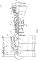
- FIG. 1 schematically illustrates a gas turbine engine 20.
- the gas turbine engine 20 is disclosed herein as a two-spool turbofan that generally incorporates a fan section 22, a compressor section 24, a combustor section 26 and a turbine section 28.
- Alternative engines might include other systems or features.
- the fan section 22 drives air along a bypass flow path B in a bypass duct, while the compressor section 24 drives air along a core flow path C for compression and communication into the combustor section 26 then expansion through the turbine section 28.
- FIG. 1 schematically illustrates a gas turbine engine 20.
- the gas turbine engine 20 is disclosed herein as a two-spool turbofan that generally incorporates a fan section 22, a compressor section 24, a combustor section 26 and a turbine section 28.
- Alternative engines might include other systems or features.
- the fan section 22 drives air along a bypass flow path B in a bypass duct
- the compressor section 24 drives air along a core flow path C for compression and communication into the combustor section 26
- the exemplary engine 20 generally includes a low speed spool 30 and a high speed spool 32 mounted for rotation about an engine central longitudinal axis A relative to an engine static structure 36 via several bearing systems 38. It should be understood that various bearing systems 38 at various locations may alternatively or additionally be provided, and the location of bearing systems 38 may be varied as appropriate to the application.
- the low speed spool 30 generally includes an inner shaft 40 that interconnects a fan 42, a low pressure compressor 44 and a low pressure turbine 46.
- the inner shaft 40 is connected to the fan 42 through a speed change mechanism, which in exemplary gas turbine engine 20 is illustrated as a geared architecture 48 to drive the fan 42 at a lower speed than the low speed spool 30.
- the high speed spool 32 includes an outer shaft 50 that interconnects a high pressure compressor 52 and high pressure turbine 54.
- a combustor 56 is arranged in exemplary gas turbine 20 between the high pressure compressor 52 and the high pressure turbine 54.
- An engine static structure 36 is arranged generally between the high pressure turbine 54 and the low pressure turbine 46.
- the engine static structure 36 further supports bearing systems 38 in the turbine section 28.
- the inner shaft 40 and the outer shaft 50 are concentric and rotate via bearing systems 38 about the engine central longitudinal axis A which is collinear with their longitudinal axes.
- each of the positions of the fan section 22, compressor section 24, combustor section 26, turbine section 28, and fan drive gear system 48 may be varied.
- gear system 48 may be located aft of combustor section 26 or even aft of turbine section 28, and fan section 22 may be positioned forward or aft of the location of gear system 48.
- the engine 20 in one example is a high-bypass geared aircraft engine.
- the engine 20 bypass ratio is greater than about six (6), with an example embodiment being greater than about ten (10)
- the geared architecture 48 is an epicyclic gear train, such as a planetary gear system or other gear system, with a gear reduction ratio of greater than about 2.3 and the low pressure turbine 46 has a pressure ratio that is greater than about five.
- the engine 20 bypass ratio is greater than about ten (10:1)
- the fan diameter is significantly larger than that of the low pressure compressor 44
- the low pressure turbine 46 has a pressure ratio that is greater than about five (5:1).
- Low pressure turbine 46 pressure ratio is pressure measured prior to inlet of low pressure turbine 46 as related to the pressure at the outlet of the low pressure turbine 46 prior to an exhaust nozzle.
- the geared architecture 48 may be an epicycle gear train, such as a planetary gear system or other gear system, with a gear reduction ratio of greater than about 2.3:1. It should be understood, however, that the above parameters are only exemplary of one embodiment of a geared architecture engine and that the present disclosure is applicable to other gas turbine engines including direct drive turbofans.
- the fan section 22 of the engine 20 is designed for a particular flight condition--typically cruise at about 0.8 Mach and about 35,000 feet (10,668 meters).
- 'TSFC' Thrust Specific Fuel Consumption
- Low fan pressure ratio is the pressure ratio across the fan blade alone, without a Fan Exit Guide Vane (“FEGV”) system.
- the low fan pressure ratio as disclosed herein according to one non-limiting embodiment is less than about 1.45.
- Low corrected fan tip speed is the actual fan tip speed in ft/sec divided by an industry standard temperature correction of [(Tram °R)/(518.7 °R)] 0.5 .
- the "Low corrected fan tip speed” as disclosed herein according to one non-limiting embodiment is less than about 1150 ft/second (350.5 m/sec).
- the first component 122 is a link 126 having an eye 128 arranged at a first end 130 thereof and a spherical bearing 132 is located within the eye 128.
- the second component 124 is a bracket or housing arranged generally adjacent or in alignment with the eye 128 and/or spherical bearing 132.
- the second component 124 has a first portion 124a and a second portion 124b that define an opening 134 within which the first end 130 and the spherical bearing 132 of the first component 124 are received.
- a through hole 136 extends through the first portion 124a of the second component 124, the spherical bearing 132, and at least part of the second portion 124b of the second component 124, such that a fastener 140 may be installed therein to couple the spherical bearing 132 and the link 126 to the first and second portions 124a, 124b of the second component 124.
- the second component 124 includes only a first portion 124a configured to couple to the first component 122 are also within the scope of the disclosure.
- the first and second components 122, 124 are part of an actuation system, such as used in a high pressure compressor of a gas turbine engine, such as shown in FIG. 1 for example; however, it should be understood that any interface 120 between two components is contemplated herein.
- Bracket feature 144 Protruding from a surface of the second component 124, such as from a surface 142 of the first portion 124a of the second component 124 for example, is at least one bracket feature 144.
- the at least one bracket feature 144 protrudes generally perpendicular from the surface 142, parallel to the axis X defined by the through hole 136.
- the second component 124 includes four bracket features 144 equidistantly spaced about the through hole 136.
- a second component 124 having any number of bracket features 144 is within the scope of the disclosure.
- the bracket features 144 may be substantially identical, or alternatively, may vary in configuration based on the position of the feature 44 relative to the second component 124.
- the one or more bracket features 144 are positioned so as not to interfere with the receipt of one or more components, such as the fastener 140, within the through hole 136.
- the bracket features 144 define one or more clearances 146 extending radially from an exterior of the fastener 140 to an outer periphery of the surface 142.
- a fastener 140 such as a screw or bolt is received within the through hole 136 of the second component 124 and the adjacent and complementary through hole 138 (see FIG. 2 ) formed in the first component 122.
- the fastener 140 includes a wrenching feature 148, such as a shaped indentation formed in the head 150 of the fastener 140.
- the wrenching feature 148 is configured to receive a tool, such as an Allen wrench or screwdriver for example, which is operable to apply a torque to the fastener 140, to further couple the fastener 140 to at least one of the first and second component.
- a locking plate 160 may be coupled to the fastener 140 to restrict this reverse rotation of the fastener 140 out of engagement with the first and/or second component 122, 124.
- the locking plate 160 includes a base 162 having a generally planar surface 164 adapted to contact the exposed upper surface of the head 150.
- the base 162 further includes at least one locking portion 166, which is receivable against a surface 142 of the second component 124, at a position located radially outward from the fastener 140.
- the locking portion 166 is received within a clearance 146 defined by the at least one bracket feature 144.
- the engagement between the locking portion 166 and the one or more adjacent bracket features 144 restricts rotation of the locking plate 160 in a direction associated with decoupling the fastener 140 from the first and second components 122, 124.
- the base 162 of the locking plate 160 includes a plurality of locking portions 166, such as two locking portions, as shown in the FIGS.
- the plurality of locking portions 166 are shown as being axially aligned and spaced 180° from one another, embodiments where the plurality of locking portions 166 are arranged at another angle relative to one another are also within the scope of the disclosure.
- the configuration of the plurality of locking portions 166 may be selected in response to the application in which the locking plate 160 is being used and the configuration of the at least one bracket feature 144.
- the locking plate 160 additionally includes a key 168 configured to couple the base 162 of the locking plate 160 to the fastener 140.
- the key 168 typically has a size and shape corresponding to the wrenching feature 48 formed in the fastener 40, such that the key 168 is receivable within the wrenching feature 148 in a manner similar to a tool.
- the key 168 is designed such that the key 168 is not able to rotate relative to the fastener 40 once installed within the wrenching feature 48.
- the key 168 is integrally formed with the base 162.
- the key 168 protrudes from a first surface of the base 162, such as surface 164 for example, such that when the locking portion 166 is aligned with a clearance 146, the key 168 is axially aligned with the wrenching feature 148.
- limited rotation of the fastener 140 may be required, prior to installation of the locking plate 160, to position the wrenching feature 148 such that the key 168 is receivable therein when the locking portion 166 is arranged within the clearance 146.
- a second key 168 may protrude from a second opposite surface 170 of the base 162. Although the first key 168 and the second key 168 are substantially identical, the second key 168 is rotated at an angle relative to the first key 168 such that a greater number of configurations of the key 168 relative to the base 162 are provided when the locking portion 166 is aligned with a clearance 146.
- the key 168 and the base 162 are formed as separate components. Accordingly, an opening 172 may be formed in the base 162 of the locking plate 160 for receipt of a key 168 therein. In such embodiments, a first portion of the key 168 is installed within the wrenching feature 148 and a second portion of the key 168 is coupled to the base 162 via the opening 172. In an embodiment, the opening 172 may be substantially identical to the configuration of the key 168, as shown in FIG. 8 . However, in another embodiment ( FIG. 9 ), the opening 172 may be configured to receive the key 168 in a variety of configurations where the key is rotated about the longitudinal axis X defined by the fastener 140.
- the rotation of the fastener 140 required to align the key 168 arranged within the wrenching feature 148 with the opening 172 of the base 162 when a locking portion 166 of the base 162 is arranged within a clearance 146 defined by the bracket features 144 is reduced.
- one or more components may be used to restrict axial movement of the locking plate 160 away from the fastener 140, i.e. out of engagement with the wrenching feature 148.
- a groove 174 is formed in an inner surface 176 of the at least one bracket feature 144 and a retaining ring 178, such as a snap ring for example, may be positioned therein.
- the groove 174 is vertically positioned such that at least a portion of the key 168 is always arranged within the wrenching feature 148.
- other methods and/or components for restricting movement of the locking plate 160 relative to the fastener 140 such as a set screw for example, are also within the scope of the disclosure.
- the interface 120 including the locking plate 160 illustrated and described herein does not rely of the clamping force of the fastener 140 to restrict rotation of the fastener 140 out of engagement with the first and second components 122, 124. Further, although a fastener 140 having a custom wrenching feature 148 may be used, standard fasteners 140 having a wrenching feature 148 formed therein are also suitable.
Landscapes
- Engineering & Computer Science (AREA)
- General Engineering & Computer Science (AREA)
- Mechanical Engineering (AREA)
- Chemical & Material Sciences (AREA)
- Combustion & Propulsion (AREA)
- Connection Of Plates (AREA)
- Structures Of Non-Positive Displacement Pumps (AREA)
Abstract
Description
- Embodiments of the present disclosure pertain to the art of fasteners, and more specifically, to a locking apparatus including locking features that prevent a threaded fastener from rotating.
- Fasteners, such as threaded bolts or studs, are often used to connect two or more components together. In some applications, it is important to ensure that the threaded fastening element does not rotate once installed relative to the components. Existing anti-rotation devices may be used to prevent unwanted rotation of such fasteners. However, these anti-rotation devices may have shortcomings. For example, depending on the geometry of the components being mated, installation of a anti-rotation device may not be feasible. Accordingly, it is desirable to provide an improved anti-rotation device for a fastener.
- Viewed from a first aspect, there is provided a locking plate for restricting rotation of a fastener connecting a first component of a gas turbine engine and a second component of a gas turbine engine which includes a base having a planar surface receivable in overlapping arrangement with a head of the fastener. A locking portion extends from the base. Engagement between the locking portion and the first component restricts rotation of the locking portion. A key extends from the base and is connectable to the fastener such that the fastener is not rotatable relative to the key when the locking portion has engaged the first component.
- In further embodiments the key may be integrally formed with the base.
- In further embodiments the key may be configured to couple to the base.
- In further embodiments the base may further comprise an opening for receiving the key.
- In further embodiments the opening may be substantially identical in size and shape to the key.
- In further embodiments the opening may be configured to receive the key in a first configuration and a second configuration, wherein in the second configuration, the key is rotated relative to the first configuration.
- Further embodiments may comprise another key extending from the base and connectable to the fastener such that the fastener is not rotatable relative to the another key.
- In further embodiments the another key may be rotated relative to the key about an axis defined by the key and the another key.
- Viewed from a second aspect, there is provided an interface including a first component including a bracket having a first hole formed therein and a second component including a link coupled to a spherical bearing. The spherical bearing has a second hole formed therein. The second component is positioned adjacent the first component such that the first hole and the second hole are axially aligned. A fastener is positioned within the first hole and the second hole to couple the first component to the second component. A locking plate is receivable in overlapping arrangement with the fastener. The locking plate includes a first portion rotatably coupled to the fastener and a second portion configured to cooperate with the first component to restrict rotation of the locking plate about the longitudinal axis of the fastener.
- In further embodiments the locking plate may include a base receivable in overlapping arrangement with the fastener, and the first portion of the locking plate may include a key and the second portion of the locking plate may include a locking portion.
- In further embodiments the key may be integrally formed with the base.
- In further embodiments the key may be configured to couple to the base.
- In further embodiments the fastener may further comprise a head having a wrenching feature formed therein, and the key may be receivable within the wrenching feature to rotatably couple the locking plate to the fastener.
- In further embodiments the first component may further comprise a surface and at least one bracket feature extending from the surface of the first component.
- In further embodiments the locking portion may cooperate with the at least one bracket feature to restrict rotation of the locking plate about the longitudinal axis of the fastener.
- Further embodiments may comprise a retaining ring positioned to restrict axial movement of the locking plate out of engagement with the fastener.
- In further embodiments the at least one bracket feature may further comprise an inner surface having a groove formed therein, the retaining ring being mounted within the at least one groove.
- In further embodiments the first component and the second component may be part of an actuation system usable in a high pressure compressor of a gas turbine engine.
- Viewed from a third aspect, there is provided a method of restricting rotation of a fastener including coupling a first component and a second component via a fastener, positioning a locking portion of a locking plate within a clearance defined by one of the first component and the second component to restrict rotation of the locking plate in a first direction, aligning a wrenching feature of the fastener with a key extending from the locking plate, and installing the key within the wrenching feature to rotatably couple the key to the locking plate.
- Further embodiments may comprise installing a retaining ring to restrict axial movement of the locking plate out of engagement with the fastener.
- The following descriptions should not be considered limiting in any way. With reference to the accompanying drawings, like elements are numbered alike:
-
FIG. 1 is a partial cross-sectional view of a gas turbine engine; -
FIG. 2 is perspective view of an interface between a first component and a second component according to an embodiment; -
FIG. 3 is a cross-sectional view of the interface ofFIG. 2 taken along line A-A according to an embodiment; -
FIG. 4 is a perspective view of at least one bracket feature formed in a surface of the second component according to an embodiment; -
FIG. 5 is a plan view of a locking plate installed relative to the at least one bracket feature formed in a surface of the second component according to an embodiment; -
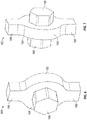
FIG. 6 is a perspective view of a locking plate according to an embodiment; -
FIG. 7 is a perspective view of another locking plate according to an embodiment; -
FIG. 8 is a perspective view of a base of a locking plate according to an embodiment; and -
FIG. 9 is a perspective view of another base of a locking plate according to an embodiment. - A detailed description of one or more embodiments of the disclosed apparatus and method are presented herein by way of exemplification and not limitation with reference to the Figures.
-
FIG. 1 schematically illustrates agas turbine engine 20. Thegas turbine engine 20 is disclosed herein as a two-spool turbofan that generally incorporates afan section 22, acompressor section 24, acombustor section 26 and aturbine section 28. Alternative engines might include other systems or features. Thefan section 22 drives air along a bypass flow path B in a bypass duct, while thecompressor section 24 drives air along a core flow path C for compression and communication into thecombustor section 26 then expansion through theturbine section 28. Although depicted as a two-spool turbofan gas turbine engine in the disclosed non-limiting embodiment, it should be understood that the concepts described herein are not limited to use with two-spool turbofans as the teachings may be applied to other types of turbine engines including three-spool architectures. - The
exemplary engine 20 generally includes alow speed spool 30 and ahigh speed spool 32 mounted for rotation about an engine central longitudinal axis A relative to an enginestatic structure 36 viaseveral bearing systems 38. It should be understood thatvarious bearing systems 38 at various locations may alternatively or additionally be provided, and the location ofbearing systems 38 may be varied as appropriate to the application. - The
low speed spool 30 generally includes aninner shaft 40 that interconnects afan 42, alow pressure compressor 44 and alow pressure turbine 46. Theinner shaft 40 is connected to thefan 42 through a speed change mechanism, which in exemplarygas turbine engine 20 is illustrated as a gearedarchitecture 48 to drive thefan 42 at a lower speed than thelow speed spool 30. Thehigh speed spool 32 includes anouter shaft 50 that interconnects ahigh pressure compressor 52 andhigh pressure turbine 54. Acombustor 56 is arranged inexemplary gas turbine 20 between thehigh pressure compressor 52 and thehigh pressure turbine 54. An enginestatic structure 36 is arranged generally between thehigh pressure turbine 54 and thelow pressure turbine 46. The enginestatic structure 36 further supports bearingsystems 38 in theturbine section 28. Theinner shaft 40 and theouter shaft 50 are concentric and rotate viabearing systems 38 about the engine central longitudinal axis A which is collinear with their longitudinal axes. - The core airflow is compressed by the
low pressure compressor 44 then thehigh pressure compressor 52, mixed and burned with fuel in thecombustor 56, then expanded over thehigh pressure turbine 54 andlow pressure turbine 46. Theturbines low speed spool 30 andhigh speed spool 32 in response to the expansion. It will be appreciated that each of the positions of thefan section 22,compressor section 24,combustor section 26,turbine section 28, and fandrive gear system 48 may be varied. For example,gear system 48 may be located aft ofcombustor section 26 or even aft ofturbine section 28, andfan section 22 may be positioned forward or aft of the location ofgear system 48. - The
engine 20 in one example is a high-bypass geared aircraft engine. In a further example, theengine 20 bypass ratio is greater than about six (6), with an example embodiment being greater than about ten (10), the gearedarchitecture 48 is an epicyclic gear train, such as a planetary gear system or other gear system, with a gear reduction ratio of greater than about 2.3 and thelow pressure turbine 46 has a pressure ratio that is greater than about five. In one disclosed embodiment, theengine 20 bypass ratio is greater than about ten (10:1), the fan diameter is significantly larger than that of thelow pressure compressor 44, and thelow pressure turbine 46 has a pressure ratio that is greater than about five (5:1).Low pressure turbine 46 pressure ratio is pressure measured prior to inlet oflow pressure turbine 46 as related to the pressure at the outlet of thelow pressure turbine 46 prior to an exhaust nozzle. The gearedarchitecture 48 may be an epicycle gear train, such as a planetary gear system or other gear system, with a gear reduction ratio of greater than about 2.3:1. It should be understood, however, that the above parameters are only exemplary of one embodiment of a geared architecture engine and that the present disclosure is applicable to other gas turbine engines including direct drive turbofans. - A significant amount of thrust is provided by the bypass flow B due to the high bypass ratio. The
fan section 22 of theengine 20 is designed for a particular flight condition--typically cruise at about 0.8 Mach and about 35,000 feet (10,668 meters). The flight condition of 0.8 Mach and 35,000 ft (10,668 meters), with the engine at its best fuel consumption--also known as "bucket cruise Thrust Specific Fuel Consumption ('TSFC')"--is the industry standard parameter of lbm of fuel being burned divided by lbf of thrust the engine produces at that minimum point. "Low fan pressure ratio" is the pressure ratio across the fan blade alone, without a Fan Exit Guide Vane ("FEGV") system. The low fan pressure ratio as disclosed herein according to one non-limiting embodiment is less than about 1.45. "Low corrected fan tip speed" is the actual fan tip speed in ft/sec divided by an industry standard temperature correction of [(Tram °R)/(518.7 °R)]0.5. The "Low corrected fan tip speed" as disclosed herein according to one non-limiting embodiment is less than about 1150 ft/second (350.5 m/sec). - With reference now to
FIGS. 2 and3 , an example of aninterface 120 between afirst component 122 and asecond component 124 is illustrated. In an embodiment, thefirst component 122 is alink 126 having aneye 128 arranged at afirst end 130 thereof and aspherical bearing 132 is located within theeye 128. Thesecond component 124 is a bracket or housing arranged generally adjacent or in alignment with theeye 128 and/orspherical bearing 132. In the illustrated, non-limiting embodiment, thesecond component 124 has afirst portion 124a and asecond portion 124b that define anopening 134 within which thefirst end 130 and thespherical bearing 132 of thefirst component 124 are received. A throughhole 136 extends through thefirst portion 124a of thesecond component 124, thespherical bearing 132, and at least part of thesecond portion 124b of thesecond component 124, such that afastener 140 may be installed therein to couple thespherical bearing 132 and thelink 126 to the first andsecond portions second component 124. Embodiments where thesecond component 124 includes only afirst portion 124a configured to couple to thefirst component 122 are also within the scope of the disclosure. In the illustrated, non-limiting embodiment, the first andsecond components FIG. 1 for example; however, it should be understood that anyinterface 120 between two components is contemplated herein. - Protruding from a surface of the
second component 124, such as from asurface 142 of thefirst portion 124a of thesecond component 124 for example, is at least onebracket feature 144. The at least onebracket feature 144 protrudes generally perpendicular from thesurface 142, parallel to the axis X defined by the throughhole 136. In the illustrated, non-limiting embodiment, best shown inFIG. 4 , thesecond component 124 includes fourbracket features 144 equidistantly spaced about the throughhole 136. However, asecond component 124 having any number of bracket features 144 is within the scope of the disclosure. In embodiments including a plurality of bracket features 144, the bracket features 144 may be substantially identical, or alternatively, may vary in configuration based on the position of thefeature 44 relative to thesecond component 124. The one or more bracket features 144 are positioned so as not to interfere with the receipt of one or more components, such as thefastener 140, within the throughhole 136. In an embodiment, the bracket features 144 define one ormore clearances 146 extending radially from an exterior of thefastener 140 to an outer periphery of thesurface 142. - As best shown in
FIG. 3 , afastener 140, such as a screw or bolt is received within the throughhole 136 of thesecond component 124 and the adjacent and complementary through hole 138 (seeFIG. 2 ) formed in thefirst component 122. Thefastener 140 includes awrenching feature 148, such as a shaped indentation formed in thehead 150 of thefastener 140. Thewrenching feature 148 is configured to receive a tool, such as an Allen wrench or screwdriver for example, which is operable to apply a torque to thefastener 140, to further couple thefastener 140 to at least one of the first and second component. - During operation of the system that defines the
interface 120 between the first andsecond component fastener 140 to loosen. With reference now toFIGS. 5-9 , alocking plate 160 may be coupled to thefastener 140 to restrict this reverse rotation of thefastener 140 out of engagement with the first and/orsecond component plate 160 includes a base 162 having a generallyplanar surface 164 adapted to contact the exposed upper surface of thehead 150. The base 162 further includes at least one lockingportion 166, which is receivable against asurface 142 of thesecond component 124, at a position located radially outward from thefastener 140. The lockingportion 166 is received within aclearance 146 defined by the at least onebracket feature 144. When the lockingportion 166 is arranged within theclearance 146, the engagement between the lockingportion 166 and the one or more adjacent bracket features 144 restricts rotation of thelocking plate 160 in a direction associated with decoupling thefastener 140 from the first andsecond components - In some embodiments, the
base 162 of thelocking plate 160 includes a plurality of lockingportions 166, such as two locking portions, as shown in the FIGS. However, alocking plate 160 including any number of locking portions, including asingle locking portion 166 or more than two lockingportions 166, is contemplated herein. Although the plurality of lockingportions 166 are shown as being axially aligned and spaced 180° from one another, embodiments where the plurality of lockingportions 166 are arranged at another angle relative to one another are also within the scope of the disclosure. The configuration of the plurality of lockingportions 166 may be selected in response to the application in which thelocking plate 160 is being used and the configuration of the at least onebracket feature 144. - The locking
plate 160 additionally includes a key 168 configured to couple thebase 162 of thelocking plate 160 to thefastener 140. The key 168 typically has a size and shape corresponding to thewrenching feature 48 formed in thefastener 40, such that the key 168 is receivable within thewrenching feature 148 in a manner similar to a tool. The key 168 is designed such that the key 168 is not able to rotate relative to thefastener 40 once installed within the wrenchingfeature 48. In an embodiment, best shown inFIG. 6 , the key 168 is integrally formed with thebase 162. In such embodiments, the key 168 protrudes from a first surface of thebase 162, such assurface 164 for example, such that when the lockingportion 166 is aligned with aclearance 146, the key 168 is axially aligned with thewrenching feature 148. - In some embodiments, limited rotation of the
fastener 140 may be required, prior to installation of thelocking plate 160, to position thewrenching feature 148 such that the key 168 is receivable therein when the lockingportion 166 is arranged within theclearance 146. To reduce the rotation that may be required, asecond key 168 may protrude from a second opposite surface 170 of thebase 162. Although thefirst key 168 and thesecond key 168 are substantially identical, thesecond key 168 is rotated at an angle relative to thefirst key 168 such that a greater number of configurations of the key 168 relative to the base 162 are provided when the lockingportion 166 is aligned with aclearance 146. - In another embodiment, best shown in
FIGS. 8 and9 , the key 168 and the base 162 are formed as separate components. Accordingly, anopening 172 may be formed in thebase 162 of thelocking plate 160 for receipt of a key 168 therein. In such embodiments, a first portion of the key 168 is installed within thewrenching feature 148 and a second portion of the key 168 is coupled to thebase 162 via theopening 172. In an embodiment, theopening 172 may be substantially identical to the configuration of the key 168, as shown inFIG. 8 . However, in another embodiment (FIG. 9 ), theopening 172 may be configured to receive the key 168 in a variety of configurations where the key is rotated about the longitudinal axis X defined by thefastener 140. In such embodiments, the rotation of thefastener 140 required to align the key 168 arranged within thewrenching feature 148 with theopening 172 of the base 162 when a lockingportion 166 of thebase 162 is arranged within aclearance 146 defined by the bracket features 144 is reduced. - In an embodiment, one or more components may be used to restrict axial movement of the
locking plate 160 away from thefastener 140, i.e. out of engagement with thewrenching feature 148. In the non-limiting embodiment ofFIGS. 4 and5 , agroove 174 is formed in aninner surface 176 of the at least onebracket feature 144 and a retainingring 178, such as a snap ring for example, may be positioned therein. As shown, thegroove 174 is vertically positioned such that at least a portion of the key 168 is always arranged within thewrenching feature 148. However, it should be understood that other methods and/or components for restricting movement of thelocking plate 160 relative to thefastener 140, such as a set screw for example, are also within the scope of the disclosure. - The
interface 120 including thelocking plate 160 illustrated and described herein does not rely of the clamping force of thefastener 140 to restrict rotation of thefastener 140 out of engagement with the first andsecond components fastener 140 having acustom wrenching feature 148 may be used,standard fasteners 140 having awrenching feature 148 formed therein are also suitable. - The term "about" is intended to include the degree of error associated with measurement of the particular quantity based upon the equipment available at the time of filing the application.
- The terminology used herein is for the purpose of describing particular embodiments only and is not intended to be limiting of the present disclosure. As used herein, the singular forms "a", "an" and "the" are intended to include the plural forms as well, unless the context clearly indicates otherwise. It will be further understood that the terms "comprises" and/or "comprising," when used in this specification, specify the presence of stated features, integers, steps, operations, elements, and/or components, but do not preclude the presence or addition of one or more other features, integers, steps, operations, element components, and/or groups thereof.
- While the present disclosure has been described with reference to an exemplary embodiment or embodiments, it will be understood by those skilled in the art that various changes may be made and equivalents may be substituted for elements thereof without departing from the scope of the present disclosure. In addition, many modifications may be made to adapt a particular situation or material to the teachings of the present disclosure without departing from the essential scope thereof. Therefore, it is intended that the present disclosure not be limited to the particular embodiment disclosed as the best mode contemplated for carrying out this present disclosure, but that the present disclosure will include all embodiments falling within the scope of the claims.
Claims (15)
- A locking plate (160) for restricting rotation of a fastener (140) connecting a first component (124) of a gas turbine engine (20) and a second component (122) of a gas turbine engine, comprising:a base (162) having a planar surface (164) receivable in overlapping arrangement with a head (150) of the fastener;a locking portion (166) extending from the base wherein engagement between the locking portion and the first component restricts rotation of the locking portion; anda key (168) extending from the base and connectable to the fastener such that the fastener is not rotatable relative to the key when the locking portion has engaged the first component.
- The locking plate of claim 1, wherein the key (168) is integrally formed with the base (162);
or wherein the key (168) is configured to couple to the base (162). - The locking plate of claim 1 or 2, wherein the base (162) further comprises an opening (172), for receiving the key (168);
optionally wherein the opening (172) is substantially identical in size and shape to the key (168). - The locking plate of claim 3, wherein the opening (172) is configured to receive the key (168) in a first configuration and a second configuration, wherein in the second configuration, the key is rotated relative to the first configuration.
- The locking plate of any preceding claim, further comprising another key (168) extending from the base (162) and connectable to the fastener (140) such that the fastener is not rotatable relative to the another key;
optionally wherein the another key (168) is rotated relative to the key (168) about an axis defined by the key and the another key. - An interface (120) comprising:a first component (124) including a bracket (144) having a first hole (136) formed therein;a second component (122) including a link (126) coupled to a spherical bearing (132), the spherical bearing having a second hole (138) formed therein, the second component being positioned adjacent the first component such that the first hole and the second hole are axially aligned;a fastener (140) positioned within the first hole and the second hole to couple the first component to the second component; anda locking plate (160) receivable in overlapping arrangement with the fastener, the locking plate including a first portion (124a) rotatably coupled to the fastener and a second portion (124b) configured to cooperate with the first component to restrict rotation of the locking plate about the longitudinal axis of the fastener.
- The interface of claim 6, wherein the locking plate (160) includes a base (162) receivable in overlapping arrangement with the fastener (140), and the first portion (124a) of the locking plate includes a key (168) and the second portion (124b) of the locking plate includes a locking portion (166).
- The interface of claim 7, wherein the key (168) is integrally formed with the base (162);
or wherein the key (168) is configured to couple to the base (162). - The interface of claim 7 or 8, wherein the fastener (140) further comprises a head (150) having a wrenching feature (148) formed therein, and the key (168) is receivable within the wrenching feature to rotatably couple the locking plate (160) to the fastener.
- The interface of any of claims 6 to 9, wherein the first component (124) further comprises:a surface (142); andat least one bracket feature (144) extending from the surface of the first component.
- The interface of claim 10, wherein the locking portion (166) cooperates with the at least one bracket feature (144) to restrict rotation of the locking plate (160) about the longitudinal axis of the fastener (140).
- The interface of claim 10 or 11, further comprising a retaining ring (178) positioned to restrict axial movement of the locking plate (160) out of engagement with the fastener (140);
optionally wherein the at least one bracket feature (144) further comprises an inner surface (176) having a groove (174) formed therein, the retaining ring (178) being mounted within the at least one groove. - The interface of any of claims 6 to 12, wherein the first component (124) and the second component (122) are part of an actuation system usable in a high pressure compressor of a gas turbine engine (20).
- A method of restricting rotation of a fastener (140) comprising:coupling a first component (124) and a second component (122) via a fastener (140);positioning a locking portion (166) of a locking plate (160) within a clearance (146) defined by one of the first component and the second component to restrict rotation of the locking plate in a first direction;aligning a wrenching feature (148) of the fastener with a key (168) extending from the locking plate; andinstalling the key within the wrenching feature to rotatably couple the key to the locking plate.
- The method of claim 14, further comprising installing a retaining ring (178) to restrict axial movement of the locking plate (160) out of engagement with the fastener (140).
Priority Applications (1)
| Application Number | Priority Date | Filing Date | Title |
|---|---|---|---|
| EP23168593.4A EP4219917B1 (en) | 2018-05-16 | 2019-05-15 | Anti-rotation device for fasteners |
Applications Claiming Priority (1)
| Application Number | Priority Date | Filing Date | Title |
|---|---|---|---|
| US15/981,590 US11441592B2 (en) | 2018-05-16 | 2018-05-16 | Anti-rotation device for fasteners |
Related Child Applications (1)
| Application Number | Title | Priority Date | Filing Date |
|---|---|---|---|
| EP23168593.4A Division EP4219917B1 (en) | 2018-05-16 | 2019-05-15 | Anti-rotation device for fasteners |
Publications (2)
| Publication Number | Publication Date |
|---|---|
| EP3569839A1 true EP3569839A1 (en) | 2019-11-20 |
| EP3569839B1 EP3569839B1 (en) | 2023-04-19 |
Family
ID=66770156
Family Applications (2)
| Application Number | Title | Priority Date | Filing Date |
|---|---|---|---|
| EP23168593.4A Active EP4219917B1 (en) | 2018-05-16 | 2019-05-15 | Anti-rotation device for fasteners |
| EP19174757.5A Active EP3569839B1 (en) | 2018-05-16 | 2019-05-15 | Anti-rotation device for fasteners |
Family Applications Before (1)
| Application Number | Title | Priority Date | Filing Date |
|---|---|---|---|
| EP23168593.4A Active EP4219917B1 (en) | 2018-05-16 | 2019-05-15 | Anti-rotation device for fasteners |
Country Status (2)
| Country | Link |
|---|---|
| US (1) | US11441592B2 (en) |
| EP (2) | EP4219917B1 (en) |
Cited By (1)
| Publication number | Priority date | Publication date | Assignee | Title |
|---|---|---|---|---|
| CN114687861A (en) * | 2022-05-31 | 2022-07-01 | 成都中科翼能科技有限公司 | Locking connection device of gas turbine low-pressure rotor |
Families Citing this family (4)
| Publication number | Priority date | Publication date | Assignee | Title |
|---|---|---|---|---|
| FR3077560B1 (en) * | 2018-02-06 | 2020-01-10 | Airbus Operations | ASSEMBLY FOR AN AIRCRAFT ENGINE MOUNT COMPRISING A HINGE AXIS SUPPORTED BY A SCREED AND MOVABLE IN TRANSLATION |
| DE102021120382A1 (en) | 2021-08-05 | 2023-02-09 | MTU Aero Engines AG | Connection device for an adjustable blade of a gas turbine and gas turbine |
| PL439888A1 (en) * | 2021-12-17 | 2023-06-19 | Sieć Badawcza Łukasiewicz - Instytut Lotnictwa | Module separation mechanism, especially for rockets |
| US12480657B1 (en) | 2025-04-29 | 2025-11-25 | General Electric Company | Gas turbine engine and fuel nozzle therefor |
Citations (4)
| Publication number | Priority date | Publication date | Assignee | Title |
|---|---|---|---|---|
| US1140272A (en) * | 1914-11-21 | 1915-05-18 | Robert T Mcclure | Nut-lock. |
| US3558237A (en) * | 1969-06-25 | 1971-01-26 | Gen Motors Corp | Variable turbine nozzles |
| US20090116930A1 (en) * | 2007-11-06 | 2009-05-07 | Reimler James L | Fastener system, fastener system article, and method |
| US20170297181A1 (en) * | 2014-09-25 | 2017-10-19 | Electricite De France | Key device for holding a nut retainer |
Family Cites Families (16)
| Publication number | Priority date | Publication date | Assignee | Title |
|---|---|---|---|---|
| US1319948A (en) * | 1919-10-28 | Dkawebr-ptjll fastener | ||
| DE1531395A1 (en) * | 1967-07-18 | 1970-01-29 | Entwicklungsring Sued Gmbh | Engine suspension, especially for the jet engines of short or vertical take-off aircraft |
| US4193435A (en) * | 1978-08-31 | 1980-03-18 | Nasa | Floating nut retention system |
| US4243192A (en) * | 1978-12-04 | 1981-01-06 | Mcdonnell Douglas Corporation | Ball pivot thrust bearing flex joint |
| US4734001A (en) | 1985-07-17 | 1988-03-29 | Bennett Bruce A | Locking fastener |
| GB8722021D0 (en) * | 1987-09-18 | 1987-10-28 | British Aerospace | Lock nut assemblies |
| FR2635751B1 (en) * | 1988-09-01 | 1991-01-04 | Snecma | DEVICE FOR FIXING A SUSPENSION LINK OF A TURBO-JET |
| US4940374A (en) * | 1988-10-24 | 1990-07-10 | Gallagher Roy L | Locking bolts for vehicle exhaust manifold pipes |
| US4938644A (en) | 1989-05-22 | 1990-07-03 | Eaton Corporation | Bolt and nut lock assembly |
| USD386955S (en) * | 1996-10-18 | 1997-12-02 | Jones Darrel D | T-handle ratchet |
| FR2879695B1 (en) * | 2004-12-16 | 2007-04-06 | Snecma Moteurs Sa | DEVICE FOR CONNECTING ADJUSTABLE LENGTH BETWEEN TWO PIECES |
| WO2006135307A1 (en) * | 2005-06-13 | 2006-12-21 | Volvo Aero Corporation | A device for moving at least one moveable element in gas turbine |
| FR2893367B1 (en) * | 2005-11-17 | 2007-12-21 | Airbus France Sas | DEVICE FOR SECURING AN INSERT IN A STRUCTURE |
| US7603931B1 (en) * | 2007-11-26 | 2009-10-20 | Paul Powell | Angularly offset wrench |
| FR3014971B1 (en) * | 2013-12-12 | 2016-01-22 | Airbus Operations Sas | ASSEMBLY COMPRISING A JOINT AXLE SUPPORTED BY A CAP AND IMMOBILIZED IN TRANSLATION BY A LOCKING DEVICE INCORPORATING A DOUBLE ANTI-ROTATION SYSTEM |
| US9714675B2 (en) * | 2015-10-13 | 2017-07-25 | Sps Technologies, Llc | Locknut assembly |
-
2018
- 2018-05-16 US US15/981,590 patent/US11441592B2/en active Active
-
2019
- 2019-05-15 EP EP23168593.4A patent/EP4219917B1/en active Active
- 2019-05-15 EP EP19174757.5A patent/EP3569839B1/en active Active
Patent Citations (4)
| Publication number | Priority date | Publication date | Assignee | Title |
|---|---|---|---|---|
| US1140272A (en) * | 1914-11-21 | 1915-05-18 | Robert T Mcclure | Nut-lock. |
| US3558237A (en) * | 1969-06-25 | 1971-01-26 | Gen Motors Corp | Variable turbine nozzles |
| US20090116930A1 (en) * | 2007-11-06 | 2009-05-07 | Reimler James L | Fastener system, fastener system article, and method |
| US20170297181A1 (en) * | 2014-09-25 | 2017-10-19 | Electricite De France | Key device for holding a nut retainer |
Cited By (1)
| Publication number | Priority date | Publication date | Assignee | Title |
|---|---|---|---|---|
| CN114687861A (en) * | 2022-05-31 | 2022-07-01 | 成都中科翼能科技有限公司 | Locking connection device of gas turbine low-pressure rotor |
Also Published As
| Publication number | Publication date |
|---|---|
| EP4219917A1 (en) | 2023-08-02 |
| EP3569839B1 (en) | 2023-04-19 |
| EP4219917B1 (en) | 2025-10-22 |
| US11441592B2 (en) | 2022-09-13 |
| US20190353197A1 (en) | 2019-11-21 |
Similar Documents
| Publication | Publication Date | Title |
|---|---|---|
| EP3569839B1 (en) | Anti-rotation device for fasteners | |
| US9249676B2 (en) | Turbine rotor cover plate lock | |
| US10641313B2 (en) | Self-anti-rotating dual lock washer | |
| EP3244028A1 (en) | Fastener retention mechanism | |
| EP3708772B1 (en) | Tie shaft assembly for a gas turbine engine | |
| US11111821B2 (en) | Retention assembly for gas turbine engine | |
| EP3633153B1 (en) | Bell crank and bar assembly | |
| EP3533974B1 (en) | Variable vane arm retention feature | |
| EP3048283B1 (en) | A conduit assembly and method of utilization | |
| US11286797B2 (en) | Gas turbine engine stator vane base shape | |
| EP4202191B1 (en) | Restraining plug | |
| EP3770381A1 (en) | Self retained linkage and system including the self retained linkage for a gas turbine engine | |
| EP3508417B1 (en) | Assembly for releasable locking of a spinner or nosecone to an engine structure | |
| EP3693558A1 (en) | Integral shear locking bumper for gas turbine engine | |
| US11002147B2 (en) | Fixed vane pack retaining ring | |
| EP3431716A1 (en) | Variable-pitch vane assembly and corresponding assembly method | |
| EP3940198B1 (en) | Multi-ring spacer for gas turbine engine rotor stack assembly | |
| US11181004B2 (en) | Confinement of a rope seal about a passage using a backing plate | |
| EP4202192B1 (en) | Restraining plug | |
| US20250198311A1 (en) | Compressor rotor destacking apparatus and method | |
| EP3633218B1 (en) | Load distributing self-locking mount pin |
Legal Events
| Date | Code | Title | Description |
|---|---|---|---|
| PUAI | Public reference made under article 153(3) epc to a published international application that has entered the european phase |
Free format text: ORIGINAL CODE: 0009012 |
|
| STAA | Information on the status of an ep patent application or granted ep patent |
Free format text: STATUS: THE APPLICATION HAS BEEN PUBLISHED |
|
| AK | Designated contracting states |
Kind code of ref document: A1 Designated state(s): AL AT BE BG CH CY CZ DE DK EE ES FI FR GB GR HR HU IE IS IT LI LT LU LV MC MK MT NL NO PL PT RO RS SE SI SK SM TR |
|
| AX | Request for extension of the european patent |
Extension state: BA ME |
|
| STAA | Information on the status of an ep patent application or granted ep patent |
Free format text: STATUS: REQUEST FOR EXAMINATION WAS MADE |
|
| 17P | Request for examination filed |
Effective date: 20200520 |
|
| RBV | Designated contracting states (corrected) |
Designated state(s): AL AT BE BG CH CY CZ DE DK EE ES FI FR GB GR HR HU IE IS IT LI LT LU LV MC MK MT NL NO PL PT RO RS SE SI SK SM TR |
|
| STAA | Information on the status of an ep patent application or granted ep patent |
Free format text: STATUS: EXAMINATION IS IN PROGRESS |
|
| 17Q | First examination report despatched |
Effective date: 20210208 |
|
| RAP1 | Party data changed (applicant data changed or rights of an application transferred) |
Owner name: RAYTHEON TECHNOLOGIES CORPORATION |
|
| GRAP | Despatch of communication of intention to grant a patent |
Free format text: ORIGINAL CODE: EPIDOSNIGR1 |
|
| STAA | Information on the status of an ep patent application or granted ep patent |
Free format text: STATUS: GRANT OF PATENT IS INTENDED |
|
| INTG | Intention to grant announced |
Effective date: 20221103 |
|
| GRAS | Grant fee paid |
Free format text: ORIGINAL CODE: EPIDOSNIGR3 |
|
| GRAA | (expected) grant |
Free format text: ORIGINAL CODE: 0009210 |
|
| STAA | Information on the status of an ep patent application or granted ep patent |
Free format text: STATUS: THE PATENT HAS BEEN GRANTED |
|
| AK | Designated contracting states |
Kind code of ref document: B1 Designated state(s): AL AT BE BG CH CY CZ DE DK EE ES FI FR GB GR HR HU IE IS IT LI LT LU LV MC MK MT NL NO PL PT RO RS SE SI SK SM TR |
|
| REG | Reference to a national code |
Ref country code: GB Ref legal event code: FG4D |
|
| REG | Reference to a national code |
Ref country code: CH Ref legal event code: EP |
|
| REG | Reference to a national code |
Ref country code: DE Ref legal event code: R096 Ref document number: 602019027624 Country of ref document: DE |
|
| REG | Reference to a national code |
Ref country code: IE Ref legal event code: FG4D |
|
| REG | Reference to a national code |
Ref country code: AT Ref legal event code: REF Ref document number: 1561331 Country of ref document: AT Kind code of ref document: T Effective date: 20230515 |
|
| P01 | Opt-out of the competence of the unified patent court (upc) registered |
Effective date: 20230521 |
|
| REG | Reference to a national code |
Ref country code: LT Ref legal event code: MG9D |
|
| REG | Reference to a national code |
Ref country code: NL Ref legal event code: MP Effective date: 20230419 |
|
| REG | Reference to a national code |
Ref country code: AT Ref legal event code: MK05 Ref document number: 1561331 Country of ref document: AT Kind code of ref document: T Effective date: 20230419 |
|
| PG25 | Lapsed in a contracting state [announced via postgrant information from national office to epo] |
Ref country code: NL Free format text: LAPSE BECAUSE OF FAILURE TO SUBMIT A TRANSLATION OF THE DESCRIPTION OR TO PAY THE FEE WITHIN THE PRESCRIBED TIME-LIMIT Effective date: 20230419 |
|
| PG25 | Lapsed in a contracting state [announced via postgrant information from national office to epo] |
Ref country code: SE Free format text: LAPSE BECAUSE OF FAILURE TO SUBMIT A TRANSLATION OF THE DESCRIPTION OR TO PAY THE FEE WITHIN THE PRESCRIBED TIME-LIMIT Effective date: 20230419 Ref country code: PT Free format text: LAPSE BECAUSE OF FAILURE TO SUBMIT A TRANSLATION OF THE DESCRIPTION OR TO PAY THE FEE WITHIN THE PRESCRIBED TIME-LIMIT Effective date: 20230821 Ref country code: NO Free format text: LAPSE BECAUSE OF FAILURE TO SUBMIT A TRANSLATION OF THE DESCRIPTION OR TO PAY THE FEE WITHIN THE PRESCRIBED TIME-LIMIT Effective date: 20230719 Ref country code: ES Free format text: LAPSE BECAUSE OF FAILURE TO SUBMIT A TRANSLATION OF THE DESCRIPTION OR TO PAY THE FEE WITHIN THE PRESCRIBED TIME-LIMIT Effective date: 20230419 Ref country code: AT Free format text: LAPSE BECAUSE OF FAILURE TO SUBMIT A TRANSLATION OF THE DESCRIPTION OR TO PAY THE FEE WITHIN THE PRESCRIBED TIME-LIMIT Effective date: 20230419 |
|
| RAP4 | Party data changed (patent owner data changed or rights of a patent transferred) |
Owner name: RTX CORPORATION |
|
| PG25 | Lapsed in a contracting state [announced via postgrant information from national office to epo] |
Ref country code: RS Free format text: LAPSE BECAUSE OF FAILURE TO SUBMIT A TRANSLATION OF THE DESCRIPTION OR TO PAY THE FEE WITHIN THE PRESCRIBED TIME-LIMIT Effective date: 20230419 Ref country code: PL Free format text: LAPSE BECAUSE OF FAILURE TO SUBMIT A TRANSLATION OF THE DESCRIPTION OR TO PAY THE FEE WITHIN THE PRESCRIBED TIME-LIMIT Effective date: 20230419 Ref country code: LV Free format text: LAPSE BECAUSE OF FAILURE TO SUBMIT A TRANSLATION OF THE DESCRIPTION OR TO PAY THE FEE WITHIN THE PRESCRIBED TIME-LIMIT Effective date: 20230419 Ref country code: LT Free format text: LAPSE BECAUSE OF FAILURE TO SUBMIT A TRANSLATION OF THE DESCRIPTION OR TO PAY THE FEE WITHIN THE PRESCRIBED TIME-LIMIT Effective date: 20230419 Ref country code: IS Free format text: LAPSE BECAUSE OF FAILURE TO SUBMIT A TRANSLATION OF THE DESCRIPTION OR TO PAY THE FEE WITHIN THE PRESCRIBED TIME-LIMIT Effective date: 20230819 Ref country code: HR Free format text: LAPSE BECAUSE OF FAILURE TO SUBMIT A TRANSLATION OF THE DESCRIPTION OR TO PAY THE FEE WITHIN THE PRESCRIBED TIME-LIMIT Effective date: 20230419 Ref country code: GR Free format text: LAPSE BECAUSE OF FAILURE TO SUBMIT A TRANSLATION OF THE DESCRIPTION OR TO PAY THE FEE WITHIN THE PRESCRIBED TIME-LIMIT Effective date: 20230720 Ref country code: AL Free format text: LAPSE BECAUSE OF FAILURE TO SUBMIT A TRANSLATION OF THE DESCRIPTION OR TO PAY THE FEE WITHIN THE PRESCRIBED TIME-LIMIT Effective date: 20230419 |
|
| PG25 | Lapsed in a contracting state [announced via postgrant information from national office to epo] |
Ref country code: FI Free format text: LAPSE BECAUSE OF FAILURE TO SUBMIT A TRANSLATION OF THE DESCRIPTION OR TO PAY THE FEE WITHIN THE PRESCRIBED TIME-LIMIT Effective date: 20230419 |
|
| REG | Reference to a national code |
Ref country code: CH Ref legal event code: PL |
|
| PG25 | Lapsed in a contracting state [announced via postgrant information from national office to epo] |
Ref country code: SK Free format text: LAPSE BECAUSE OF FAILURE TO SUBMIT A TRANSLATION OF THE DESCRIPTION OR TO PAY THE FEE WITHIN THE PRESCRIBED TIME-LIMIT Effective date: 20230419 |
|
| PG25 | Lapsed in a contracting state [announced via postgrant information from national office to epo] |
Ref country code: MC Free format text: LAPSE BECAUSE OF FAILURE TO SUBMIT A TRANSLATION OF THE DESCRIPTION OR TO PAY THE FEE WITHIN THE PRESCRIBED TIME-LIMIT Effective date: 20230419 |
|
| REG | Reference to a national code |
Ref country code: DE Ref legal event code: R097 Ref document number: 602019027624 Country of ref document: DE |
|
| REG | Reference to a national code |
Ref country code: BE Ref legal event code: MM Effective date: 20230531 |
|
| PG25 | Lapsed in a contracting state [announced via postgrant information from national office to epo] |
Ref country code: SM Free format text: LAPSE BECAUSE OF FAILURE TO SUBMIT A TRANSLATION OF THE DESCRIPTION OR TO PAY THE FEE WITHIN THE PRESCRIBED TIME-LIMIT Effective date: 20230419 Ref country code: SK Free format text: LAPSE BECAUSE OF FAILURE TO SUBMIT A TRANSLATION OF THE DESCRIPTION OR TO PAY THE FEE WITHIN THE PRESCRIBED TIME-LIMIT Effective date: 20230419 Ref country code: RO Free format text: LAPSE BECAUSE OF FAILURE TO SUBMIT A TRANSLATION OF THE DESCRIPTION OR TO PAY THE FEE WITHIN THE PRESCRIBED TIME-LIMIT Effective date: 20230419 Ref country code: MC Free format text: LAPSE BECAUSE OF FAILURE TO SUBMIT A TRANSLATION OF THE DESCRIPTION OR TO PAY THE FEE WITHIN THE PRESCRIBED TIME-LIMIT Effective date: 20230419 Ref country code: LU Free format text: LAPSE BECAUSE OF NON-PAYMENT OF DUE FEES Effective date: 20230515 Ref country code: LI Free format text: LAPSE BECAUSE OF NON-PAYMENT OF DUE FEES Effective date: 20230531 Ref country code: EE Free format text: LAPSE BECAUSE OF FAILURE TO SUBMIT A TRANSLATION OF THE DESCRIPTION OR TO PAY THE FEE WITHIN THE PRESCRIBED TIME-LIMIT Effective date: 20230419 Ref country code: DK Free format text: LAPSE BECAUSE OF FAILURE TO SUBMIT A TRANSLATION OF THE DESCRIPTION OR TO PAY THE FEE WITHIN THE PRESCRIBED TIME-LIMIT Effective date: 20230419 Ref country code: CZ Free format text: LAPSE BECAUSE OF FAILURE TO SUBMIT A TRANSLATION OF THE DESCRIPTION OR TO PAY THE FEE WITHIN THE PRESCRIBED TIME-LIMIT Effective date: 20230419 Ref country code: CH Free format text: LAPSE BECAUSE OF NON-PAYMENT OF DUE FEES Effective date: 20230531 |
|
| PLBE | No opposition filed within time limit |
Free format text: ORIGINAL CODE: 0009261 |
|
| STAA | Information on the status of an ep patent application or granted ep patent |
Free format text: STATUS: NO OPPOSITION FILED WITHIN TIME LIMIT |
|
| REG | Reference to a national code |
Ref country code: IE Ref legal event code: MM4A |
|
| 26N | No opposition filed |
Effective date: 20240122 |
|
| PG25 | Lapsed in a contracting state [announced via postgrant information from national office to epo] |
Ref country code: IE Free format text: LAPSE BECAUSE OF NON-PAYMENT OF DUE FEES Effective date: 20230515 |
|
| PG25 | Lapsed in a contracting state [announced via postgrant information from national office to epo] |
Ref country code: IE Free format text: LAPSE BECAUSE OF NON-PAYMENT OF DUE FEES Effective date: 20230515 |
|
| PG25 | Lapsed in a contracting state [announced via postgrant information from national office to epo] |
Ref country code: SI Free format text: LAPSE BECAUSE OF FAILURE TO SUBMIT A TRANSLATION OF THE DESCRIPTION OR TO PAY THE FEE WITHIN THE PRESCRIBED TIME-LIMIT Effective date: 20230419 |
|
| PG25 | Lapsed in a contracting state [announced via postgrant information from national office to epo] |
Ref country code: SI Free format text: LAPSE BECAUSE OF FAILURE TO SUBMIT A TRANSLATION OF THE DESCRIPTION OR TO PAY THE FEE WITHIN THE PRESCRIBED TIME-LIMIT Effective date: 20230419 Ref country code: IT Free format text: LAPSE BECAUSE OF FAILURE TO SUBMIT A TRANSLATION OF THE DESCRIPTION OR TO PAY THE FEE WITHIN THE PRESCRIBED TIME-LIMIT Effective date: 20230419 Ref country code: BE Free format text: LAPSE BECAUSE OF NON-PAYMENT OF DUE FEES Effective date: 20230531 |
|
| PG25 | Lapsed in a contracting state [announced via postgrant information from national office to epo] |
Ref country code: BG Free format text: LAPSE BECAUSE OF FAILURE TO SUBMIT A TRANSLATION OF THE DESCRIPTION OR TO PAY THE FEE WITHIN THE PRESCRIBED TIME-LIMIT Effective date: 20230419 |
|
| PG25 | Lapsed in a contracting state [announced via postgrant information from national office to epo] |
Ref country code: BG Free format text: LAPSE BECAUSE OF FAILURE TO SUBMIT A TRANSLATION OF THE DESCRIPTION OR TO PAY THE FEE WITHIN THE PRESCRIBED TIME-LIMIT Effective date: 20230419 |
|
| PGFP | Annual fee paid to national office [announced via postgrant information from national office to epo] |
Ref country code: DE Payment date: 20250423 Year of fee payment: 7 |
|
| PGFP | Annual fee paid to national office [announced via postgrant information from national office to epo] |
Ref country code: GB Payment date: 20250423 Year of fee payment: 7 |
|
| PGFP | Annual fee paid to national office [announced via postgrant information from national office to epo] |
Ref country code: FR Payment date: 20250423 Year of fee payment: 7 |
|
| PG25 | Lapsed in a contracting state [announced via postgrant information from national office to epo] |
Ref country code: CY Free format text: LAPSE BECAUSE OF FAILURE TO SUBMIT A TRANSLATION OF THE DESCRIPTION OR TO PAY THE FEE WITHIN THE PRESCRIBED TIME-LIMIT; INVALID AB INITIO Effective date: 20190515 |
|
| PG25 | Lapsed in a contracting state [announced via postgrant information from national office to epo] |
Ref country code: HU Free format text: LAPSE BECAUSE OF FAILURE TO SUBMIT A TRANSLATION OF THE DESCRIPTION OR TO PAY THE FEE WITHIN THE PRESCRIBED TIME-LIMIT; INVALID AB INITIO Effective date: 20190515 |
|
| PG25 | Lapsed in a contracting state [announced via postgrant information from national office to epo] |
Ref country code: TR Free format text: LAPSE BECAUSE OF FAILURE TO SUBMIT A TRANSLATION OF THE DESCRIPTION OR TO PAY THE FEE WITHIN THE PRESCRIBED TIME-LIMIT Effective date: 20230419 |