EP3569738A1 - Hydrogen molecule remixing device of dish-shaped electrolytic cell - Google Patents
Hydrogen molecule remixing device of dish-shaped electrolytic cell Download PDFInfo
- Publication number
- EP3569738A1 EP3569738A1 EP18173312.2A EP18173312A EP3569738A1 EP 3569738 A1 EP3569738 A1 EP 3569738A1 EP 18173312 A EP18173312 A EP 18173312A EP 3569738 A1 EP3569738 A1 EP 3569738A1
- Authority
- EP
- European Patent Office
- Prior art keywords
- water
- anode
- cathode
- disc
- gas
- Prior art date
- Legal status (The legal status is an assumption and is not a legal conclusion. Google has not performed a legal analysis and makes no representation as to the accuracy of the status listed.)
- Granted
Links
Images





Classifications
-
- C—CHEMISTRY; METALLURGY
- C02—TREATMENT OF WATER, WASTE WATER, SEWAGE, OR SLUDGE
- C02F—TREATMENT OF WATER, WASTE WATER, SEWAGE, OR SLUDGE
- C02F1/00—Treatment of water, waste water, or sewage
- C02F1/46—Treatment of water, waste water, or sewage by electrochemical methods
- C02F1/461—Treatment of water, waste water, or sewage by electrochemical methods by electrolysis
- C02F1/46104—Devices therefor; Their operating or servicing
- C02F1/4618—Devices therefor; Their operating or servicing for producing "ionised" acidic or basic water
-
- C—CHEMISTRY; METALLURGY
- C25—ELECTROLYTIC OR ELECTROPHORETIC PROCESSES; APPARATUS THEREFOR
- C25B—ELECTROLYTIC OR ELECTROPHORETIC PROCESSES FOR THE PRODUCTION OF COMPOUNDS OR NON-METALS; APPARATUS THEREFOR
- C25B1/00—Electrolytic production of inorganic compounds or non-metals
- C25B1/01—Products
- C25B1/02—Hydrogen or oxygen
- C25B1/04—Hydrogen or oxygen by electrolysis of water
-
- C—CHEMISTRY; METALLURGY
- C25—ELECTROLYTIC OR ELECTROPHORETIC PROCESSES; APPARATUS THEREFOR
- C25B—ELECTROLYTIC OR ELECTROPHORETIC PROCESSES FOR THE PRODUCTION OF COMPOUNDS OR NON-METALS; APPARATUS THEREFOR
- C25B1/00—Electrolytic production of inorganic compounds or non-metals
- C25B1/01—Products
- C25B1/13—Ozone
-
- C—CHEMISTRY; METALLURGY
- C25—ELECTROLYTIC OR ELECTROPHORETIC PROCESSES; APPARATUS THEREFOR
- C25B—ELECTROLYTIC OR ELECTROPHORETIC PROCESSES FOR THE PRODUCTION OF COMPOUNDS OR NON-METALS; APPARATUS THEREFOR
- C25B15/00—Operating or servicing cells
- C25B15/08—Supplying or removing reactants or electrolytes; Regeneration of electrolytes
-
- C—CHEMISTRY; METALLURGY
- C25—ELECTROLYTIC OR ELECTROPHORETIC PROCESSES; APPARATUS THEREFOR
- C25B—ELECTROLYTIC OR ELECTROPHORETIC PROCESSES FOR THE PRODUCTION OF COMPOUNDS OR NON-METALS; APPARATUS THEREFOR
- C25B9/00—Cells or assemblies of cells; Constructional parts of cells; Assemblies of constructional parts, e.g. electrode-diaphragm assemblies; Process-related cell features
- C25B9/17—Cells comprising dimensionally-stable non-movable electrodes; Assemblies of constructional parts thereof
- C25B9/19—Cells comprising dimensionally-stable non-movable electrodes; Assemblies of constructional parts thereof with diaphragms
-
- C—CHEMISTRY; METALLURGY
- C25—ELECTROLYTIC OR ELECTROPHORETIC PROCESSES; APPARATUS THEREFOR
- C25B—ELECTROLYTIC OR ELECTROPHORETIC PROCESSES FOR THE PRODUCTION OF COMPOUNDS OR NON-METALS; APPARATUS THEREFOR
- C25B9/00—Cells or assemblies of cells; Constructional parts of cells; Assemblies of constructional parts, e.g. electrode-diaphragm assemblies; Process-related cell features
- C25B9/70—Assemblies comprising two or more cells
- C25B9/73—Assemblies comprising two or more cells of the filter-press type
-
- C—CHEMISTRY; METALLURGY
- C02—TREATMENT OF WATER, WASTE WATER, SEWAGE, OR SLUDGE
- C02F—TREATMENT OF WATER, WASTE WATER, SEWAGE, OR SLUDGE
- C02F1/00—Treatment of water, waste water, or sewage
- C02F1/46—Treatment of water, waste water, or sewage by electrochemical methods
- C02F1/461—Treatment of water, waste water, or sewage by electrochemical methods by electrolysis
- C02F1/467—Treatment of water, waste water, or sewage by electrochemical methods by electrolysis by electrochemical disinfection; by electrooxydation or by electroreduction
- C02F1/4672—Treatment of water, waste water, or sewage by electrochemical methods by electrolysis by electrochemical disinfection; by electrooxydation or by electroreduction by electrooxydation
-
- C—CHEMISTRY; METALLURGY
- C02—TREATMENT OF WATER, WASTE WATER, SEWAGE, OR SLUDGE
- C02F—TREATMENT OF WATER, WASTE WATER, SEWAGE, OR SLUDGE
- C02F1/00—Treatment of water, waste water, or sewage
- C02F1/46—Treatment of water, waste water, or sewage by electrochemical methods
- C02F1/461—Treatment of water, waste water, or sewage by electrochemical methods by electrolysis
- C02F1/46104—Devices therefor; Their operating or servicing
- C02F1/46109—Electrodes
- C02F2001/46152—Electrodes characterised by the shape or form
-
- C—CHEMISTRY; METALLURGY
- C02—TREATMENT OF WATER, WASTE WATER, SEWAGE, OR SLUDGE
- C02F—TREATMENT OF WATER, WASTE WATER, SEWAGE, OR SLUDGE
- C02F1/00—Treatment of water, waste water, or sewage
- C02F1/46—Treatment of water, waste water, or sewage by electrochemical methods
- C02F1/461—Treatment of water, waste water, or sewage by electrochemical methods by electrolysis
- C02F1/46104—Devices therefor; Their operating or servicing
- C02F1/4618—Devices therefor; Their operating or servicing for producing "ionised" acidic or basic water
- C02F2001/46185—Devices therefor; Their operating or servicing for producing "ionised" acidic or basic water only anodic or acidic water, e.g. for oxidizing or sterilizing
-
- C—CHEMISTRY; METALLURGY
- C02—TREATMENT OF WATER, WASTE WATER, SEWAGE, OR SLUDGE
- C02F—TREATMENT OF WATER, WASTE WATER, SEWAGE, OR SLUDGE
- C02F1/00—Treatment of water, waste water, or sewage
- C02F1/46—Treatment of water, waste water, or sewage by electrochemical methods
- C02F1/461—Treatment of water, waste water, or sewage by electrochemical methods by electrolysis
- C02F1/46104—Devices therefor; Their operating or servicing
- C02F1/4618—Devices therefor; Their operating or servicing for producing "ionised" acidic or basic water
- C02F2001/4619—Devices therefor; Their operating or servicing for producing "ionised" acidic or basic water only cathodic or alkaline water, e.g. for reducing
-
- C—CHEMISTRY; METALLURGY
- C02—TREATMENT OF WATER, WASTE WATER, SEWAGE, OR SLUDGE
- C02F—TREATMENT OF WATER, WASTE WATER, SEWAGE, OR SLUDGE
- C02F2201/00—Apparatus for treatment of water, waste water or sewage
- C02F2201/46—Apparatus for electrochemical processes
- C02F2201/461—Electrolysis apparatus
- C02F2201/46105—Details relating to the electrolytic devices
- C02F2201/46115—Electrolytic cell with membranes or diaphragms
-
- C—CHEMISTRY; METALLURGY
- C02—TREATMENT OF WATER, WASTE WATER, SEWAGE, OR SLUDGE
- C02F—TREATMENT OF WATER, WASTE WATER, SEWAGE, OR SLUDGE
- C02F2201/00—Apparatus for treatment of water, waste water or sewage
- C02F2201/46—Apparatus for electrochemical processes
- C02F2201/461—Electrolysis apparatus
- C02F2201/46105—Details relating to the electrolytic devices
- C02F2201/4612—Controlling or monitoring
- C02F2201/46125—Electrical variables
- C02F2201/4613—Inversing polarity
-
- Y—GENERAL TAGGING OF NEW TECHNOLOGICAL DEVELOPMENTS; GENERAL TAGGING OF CROSS-SECTIONAL TECHNOLOGIES SPANNING OVER SEVERAL SECTIONS OF THE IPC; TECHNICAL SUBJECTS COVERED BY FORMER USPC CROSS-REFERENCE ART COLLECTIONS [XRACs] AND DIGESTS
- Y02—TECHNOLOGIES OR APPLICATIONS FOR MITIGATION OR ADAPTATION AGAINST CLIMATE CHANGE
- Y02E—REDUCTION OF GREENHOUSE GAS [GHG] EMISSIONS, RELATED TO ENERGY GENERATION, TRANSMISSION OR DISTRIBUTION
- Y02E60/00—Enabling technologies; Technologies with a potential or indirect contribution to GHG emissions mitigation
- Y02E60/30—Hydrogen technology
- Y02E60/36—Hydrogen production from non-carbon containing sources, e.g. by water electrolysis
Definitions
- the present invention relates to a remixing device and, more particularly, to a hydrogen molecule remixing device of a dish-shaped electrolytic cell.
- An electrolyzing device is used to electrolyze water.
- the source water is electrolyzed in the anode to form oxygen molecules, ozone and anionic water, and is electrolyzed in the cathode to form hydrogen molecules (or negative hydrogen ions) and cationic water.
- the hydrogen molecules are not dissolved in the water easily.
- a first conventional electrolyzing device comprises circular, rectangular or net-shaped electrodes.
- the cationic water flow channels are arranged on the surface of the cathode, and the anionic water flow channels are arranged on the surface of the anode, so that multiple recessed portions are formed in the electrodes, thereby forming a stagnation zone.
- the hydrogen molecules easily gather in the stagnation zone and form larger bubbles, so that the hydrogen molecules cannot be dissolved in the cationic water, thereby decreasing the contents of the hydrogen molecules in the cationic water.
- a second conventional electrolyzing device comprises a static hydrogen water electrolytic cup.
- the anode has a lower portion formed with an anode chamber
- the cathode has an upper portion formed with a cathode chamber.
- An ion membrane is placed between the anode chamber and the cathode chamber and is provided with multiple holes.
- the hydrogen molecules are gathered above the cathode and form air bubbles which are lifted rapidly above the electrolytic cup, so that the hydrogen molecules produced in the cathode are not exactly dissolved in the cationic water, thereby decreasing the contents of the hydrogen molecules in the cationic water.
- the oxygen molecules produced under the anode cannot be introduced smoothly so that the oxygen molecules easily stay in the cavities under the anode, thereby increasing the impedance of the electrodes.
- the electrolyzing liquid is introduced from the cup above the cathode through the holes into the anode chamber.
- the holes extend through the anode chamber and cathode chamber.
- the electrolyzing liquid is not easily introduced into the anode chamber, and when the holes are too large, the oxygen molecules, ozone are easily introduced into the cationic water, thereby causing pollution.
- the ion membrane has to be wet fully for operation, so that the ion membrane needs to rest when the electrolysis process is operated during a determined period of time.
- a third conventional electrolyzing device comprises a low water electrolytic cell whose electrodes are arranged in an upright manner.
- the electrodes are respectively located at the left side and right side of the electrolytic cell.
- the electrolytic cell has a lower end provided with a water inlet port and an upper end provided with a water outlet port, so that the water flows from bottom to top.
- the hydrogen molecules in the cathode chamber are rapidly carried upward by the cationic water.
- the cationic water is introduced outward from the electrolytic cell and is delivered into an air chamber to enhance the contents of the hydrogen molecules.
- the air chamber occupies a larger space and increases the cost.
- the primary objective of the present invention is to provide a hydrogen molecule remixing device that efficiently enhances concentration of the hydrogen molecules in the water.
- a hydrogen molecule remixing device comprising a base, a first gas and water channelling disc located above the base, an anode located above the first gas and water channelling disc, a cathode located above the anode, an ion membrane located between the anode and the cathode, a second gas and water channelling disc located above the cathode, a cover combined with the base and located above the second gas and water channelling disc, a cationic water outlet connector extending upward from the cover, and a connector extending downward from the base.
- the first gas and water channelling disc is provided with a first collecting and guiding chamber corresponding to the base.
- the second gas and water channelling disc is provided with a plurality of second collecting and guiding chambers corresponding to the cover.
- the anode is provided with a plurality of first water inlet ports and a plurality of anode cavities.
- the anode cavities are arranged in a radiating manner.
- the cathode is provided with a plurality of second water inlet ports and a plurality of cathode cavities.
- the cathode cavities are arranged in a radiating manner.
- the connector is provided with a source water input joint and an anionic water output joint.
- source water is respectively guided through the first water inlet ports of the anode and the second water inlet ports of the cathode into the anode cavities of the anode and the cathode cavities of the cathode.
- the source water is electrolyzed in the anode cavities of the anode to form oxygen molecules, ozone and anionic water, and is electrolyzed in the cathode cavities of the cathode to form hydrogen molecules and cationic water.
- the oxygen molecules and ozone in the anode cavities of the anode are carried by the anionic water into the first collecting and guiding chamber of the first gas and water channelling disc.
- the hydrogen molecules in the cathode cavities of the cathode are carried by the cationic water into the second collecting and guiding chambers of the second gas and water channelling disc, so that the hydrogen molecules and the cationic water produce an blending reaction in the second collecting and guiding chambers, and more hydrogen molecules are dissolved into the cationic water, to increase a concentration of the hydrogen molecules in the cationic water.
- a hydrogen molecule remixing device in accordance with the preferred embodiment of the present invention comprises a base 10, a first gas and water channelling disc 30 located above the base 10, an anode 40 located above the first gas and water channelling disc 30, a cathode 60 located above the anode 40, an ion membrane 50 located between the anode 40 and the cathode 60, a second gas and water channelling disc 70 located above the cathode 60, a cover 80 combined with the base 10 and located above the second gas and water channelling disc 70, a cationic water outlet connector 85 extending upward from the cover 80, and a connector 90 extending downward from the base 10.
- the base 10 and the cover 80 have a disk shape.
- the first gas and water channelling disc 30, the anode 40, the ion membrane 50, the cathode 60 and the second gas and water channelling disc 70 are arranged between the base 10 and the cover 80.
- the first gas and water channelling disc 30 has a disk shape and is provided with a first collecting and guiding chamber 391 corresponding to the base 10.
- the second gas and water channelling disc 70 has a disk shape and is provided with a plurality of second collecting and guiding chambers 78 corresponding to the cover 80.
- the anode 40 has a disk shape and is provided with a plurality of first water inlet ports 43 and a plurality of anode cavities 42.
- the anode cavities 42 are arranged in a radiating manner. The source water is guided through the first water inlet ports 43 into the anode cavities 42 of the anode 40.
- the cathode 60 has a disk shape and is provided with a plurality of second water inlet ports 63 and a plurality of cathode cavities 62.
- the cathode cavities 62 are arranged in a radiating manner.
- the shape, size and position of the cathode cavities 62 of the cathode 60 are the same as that of the anode cavities 42 of the anode 40.
- the source water is guided through the second water inlet ports 63 into the cathode cavities 62 of the cathode 60.
- the connector 90 is provided with a source water input joint 97 and an anionic water output joint 96.
- the connector 90 includes a source water inlet chamber 95 and an anionic water exit chamber 94.
- the source water inlet chamber 95 has a diameter smaller than that of the anionic water exit chamber 94.
- the source water input joint 97 is connected to and protrudes from the source water inlet chamber 95, and the anionic water output joint 96 is connected to and protrudes from the anionic water exit chamber 94.
- the anionic water output joint 96 is connected with a anionic water outlet hose (not shown).
- the source water is respectively guided through the first water inlet ports 43 of the anode 40 and the second water inlet ports 63 of the cathode 60 into the anode cavities 42 of the anode 40 and the cathode cavities 62 of the cathode 60.
- the source water is a solution that has not been electrolyzed.
- the source water is electrolyzed in the anode cavities 42 of the anode 40 to form oxygen molecules, ozone and anionic water, and is electrolyzed in the cathode cavities 62 of the cathode 60 to form hydrogen molecules and cationic water.
- the oxygen molecules and ozone in the anode cavities 42 of the anode 40 are carried by the anionic water into the first collecting and guiding chamber 391 of the first gas and water channelling disc 30.
- the hydrogen molecules in the cathode cavities 62 of the cathode 60 are carried by the cationic water into the second collecting and guiding chambers 78 of the second gas and water channelling disc 70, so that the hydrogen molecules and the cationic water produce an blending reaction in the second collecting and guiding chambers 78, and more hydrogen molecules are dissolved into the cationic water, to increase the concentration of the hydrogen molecules in the cationic water.
- polarities of the anode 40 and the cathode 60 are interchanged.
- the base 10 has a top provided with a plurality of partitions 12 which are arranged in a radiating manner, and a plurality of anionic water flow paths 121 located between the partitions 12.
- the base 10 is provided with a conductive spacing tube 14, a first spacing ring 15 surrounding the conductive spacing tube 14, and a second spacing ring 16 surrounding the first spacing ring 15.
- the base 10 is provided with a plurality of first spacing ribs 151 located between the first spacing ring 15 and the conductive spacing tube 14 and forming a plurality of source water inlet paths 152 in the first spacing ring 15, and a plurality of second spacing ribs 161 located between the second spacing ring 16 and the first spacing ring 15 and forming a plurality of anionic water outlet paths 162 in the second spacing ring 16.
- the second spacing ring 16 is provided with a plurality of anionic water outlet ports 163 corresponding to the anionic water flow paths 121.
- the anionic water outlet paths 162 have a bottom provided with a plurality of anionic water outlet holes 164.
- the top of the base 10 is provided with an annular flange 17 surrounding the partitions 12, and a connecting groove 171 is formed between an inner wall of the base 10 and the annular flange 17 for connecting the first gas and water channelling disc 30.
- the first gas and water channelling disc 30 has an outer wall provided with an annular groove 37 corresponding to the connecting groove 171 of the base 10, and an O-ring "Q" is compressed between the connecting groove 171 of the base 10 and the annular groove 37 of the first gas and water channelling disc 30, to prevent the cationic water and the anionic water from being mixed.
- the base 10 is provided with a mounting protrusion 11 extending downward for mounting the connector 90.
- the mounting protrusion 11 of the base 10 is provided with at least one tenon 112.
- the connector 90 is provided with a mounting recess 92 mounted on the mounting protrusion 11 of the base 10.
- the mounting recess 92 of the connector 90 is provided with at least one mortise 93 locked onto the tenon 112 of the mounting protrusion 11 by rotation, so that the connector 90 is locked onto or unlocked from the base 10 quickly.
- the mounting protrusion 11 of the base 10 is provided with two grooves 111 for mounting two O-rings "Q".
- the anionic water outlet holes 164 correspond to a periphery of the mounting protrusion 11.
- the base 10 is provided with an external thread 18, and the cover 80 is provided with an internal thread 81 screwed onto the external thread 18 of the base 10.
- the base 10 is provided with an annular groove 19 located above the external thread 18, and an O-ring "Q" is retained in the annular groove 19 of the base 10 and compressed between the base 10 and the cover 80.
- the anode 40 has a periphery provided with a plurality of first positioning portions 44
- the cathode 60 has a periphery provided with a plurality of second positioning portions 64 located on the first positioning portions 44 of the anode 40 to align the anode cavities 42 of the anode 40 with the cathode cavities 62 of the cathode 60, so that the anode 40 aligns with the cathode 60.
- the cover 80 is provided with a plurality of first stop flanges 82 forming a plurality of hydrogen dissolving chambers 83 in the cover 80
- the second gas and water channelling disc 70 is provided with a plurality of second stop flanges 77 forming the second collecting and guiding chambers 78 in the second gas and water channelling disc 70.
- the first stop flanges 82 of the cover 80 and the second stop flanges 77 of the second gas and water channelling disc 70 have an annular shape and are arranged alternatingly.
- Each of the first stop flanges 82 of the cover 80 is provided with a plurality of first openings 84 to collect the hydrogen molecules and guide the cationic water
- each of the second stop flanges 77 of the second gas and water channelling disc 70 is provided with a plurality of second openings 79 to collect the hydrogen molecules and guide the cationic water, so as to rapidly receive the hydrogen molecules produced by the cathode 60.
- the cationic water is moved upward and downward in the second collecting and guiding chambers 78 of the second gas and water channelling disc 70 and the hydrogen dissolving chambers 83 of the cover 80 to present a substantially successive S-shaped flow.
- the hydrogen molecules are lifted, and the cationic water is lowered to produce an blending reaction, so that more hydrogen molecules are dissolved into the cationic water.
- the ion membrane 50 is a proton exchange film and has a diameter greater than that of the anode 40 and that of the cathode 60.
- the first gas and water channelling disc 30 is provided with a protruding ring 362
- the second gas and water channelling disc 70 is provided with a slot 72 mounted on the protruding ring 362 of the first gas and water channelling disc 30, and an O-ring "Q" is compressed between the protruding ring 362 of the first gas and water channelling disc 30 and the slot 72 of the second gas and water channelling disc 70, so that the ion membrane 50 is compressed by the protruding ring 362 of the first gas and water channelling disc 30 and the O-ring "Q", so as to stop a water flow, thereby preventing the cationic water and the anionic water from being mixed.
- the first gas and water channelling disc 30 has a periphery provided with a plurality of locating slots 35
- the second gas and water channelling disc 70 has a periphery provided with a plurality of locating inserts 71 inserted into the locating slots 35 of the first gas and water channelling disc 30, so that the second gas and water channelling disc 70 is positioned on the first gas and water channelling disc 30.
- an electric conductor 20 is mounted on the cathode 60 and connected with the base 10.
- the electric conductor 20 has a lower end provided with a conducting portion 26 locked in the conductive spacing tube 14 of the base 10.
- the base 10 is provided with two through holes 13, and the anode 40 is provided with two positive conducting portions 45 extending through the two through holes 13 of the base 10 and locked by two washers "R” and two nuts "N".
- Each of the two positive conducting portions 45 of the anode 40 is provided with an outer thread 46 extending through one of the two washers "R” and screwed by one of the two nuts "N".
- the connector 90 is provided with a hollow pillar 91 corresponding to the conductive spacing tube 14 of the base 10, a negative conducting shaft 98 is movably mounted in the hollow pillar 91 and connected to a negative wire (not shown), and an elastic member “S" is mounted in the hollow pillar 91 and biased between the hollow pillar 91 and the negative conducting shaft 98 to push the negative conducting shaft 98 to closely contact the conducting portion 26 of the electric conductor 20.
- the connector 90 is provided with two elastic positive conducting blades 99 corresponding to and closely contacting the two positive conducting portions 45 of the anode 40 and connected to a positive wire (not shown).
- the anode cavities 42 of the anode 40 and the cathode cavities 62 of the cathode 60 have a substantially V-shaped configuration.
- the first gas and water channelling disc 30 is provided with a first source water inlet passage 34 corresponding to the first water inlet ports 43 of the anode 40, and the second gas and water channelling disc 70 is provided with a second source water inlet passage 74 corresponding to the second water inlet ports 63 of the cathode 60.
- the first gas and water channelling disc 30 is provided with a plurality of anionic water outlet ports 36 and a plurality of anionic water outlet channels 361
- the second gas and water channelling disc 70 is provided with a plurality of cationic water outlet ports 75 and a plurality of cationic water outlet channels 76.
- the source water flows through the first water inlet ports 43 of the anode 40 into the first source water inlet passage 34 of the first gas and water channelling disc 30, and flows from the first water inlet ports 43 of the anode 40 into the anode cavities 42 of the anode 40 in a radiating manner, and finally flows out of the anionic water outlet channels 361 and the anionic water outlet ports 36 of the first gas and water channelling disc 30.
- the source water also flows through the second water inlet ports 63 of the cathode 60 into the second source water inlet passage 74 of the second gas and water channelling disc 70, and flows outward from the second water inlet ports 63 of the cathode 60 into the cathode cavities 62 of the cathode 60 in a radiating manner, and finally flows out of the cationic water outlet channels 76 and the cationic water outlet ports 75 of the second gas and water channelling disc 70.
- the first gas and water channelling disc 30 is provided with an annular stop edge 39 corresponding to the base 10 and forming the collecting and guiding space 391 between the base 10 and the first gas and water channelling disc 30, to collect the oxygen molecules and ozone and guide the anionic water, so as to rapidly receive the oxygen molecules and ozone produced by the anode 40, thereby preventing the oxygen molecules and ozone from being mixed with the cationic water.
- the first gas and water channelling disc 30 is provided with an annular projection 38 corresponding to the anionic water outlet ports 36 to lift a level of the anionic water, so that the ion membrane 50 is wet fully.
- the conductive spacing tube 14 of the base 10 is provided with an internal thread 141
- the lower end of the electric conductor 20 is provided with a lower stepped edge 24 located in the conductive spacing tube 14 of the base 10 and an external thread 23 screwed into the internal thread 141 of the conductive spacing tube 14.
- the cathode 60 has a center provided with a shaft hole 61, with the second water inlet ports 63 being located between the shaft hole 61 and the cathode cavities 62.
- the electric conductor 20 has an upper end provided with an upper stepped edge 22 resting on the cathode 60 and an outer thread 21 extending through an O-ring "Q" and the shaft hole 61 of the cathode 60, and a nut “N” is screwed onto the outer thread 21 of the electric conductor 20 to lock the cathode 60 onto the electric conductor 20.
- the electric conductor 20 is provided with an annular groove 25 located between the upper stepped edge 22 and the lower stepped edge 24, and an O-ring "Q" is retained in the annular groove 25 of the electric conductor 20 and compressed between the conductive spacing tube 14 of the base 10 and the electric conductor 20.
- the second gas and water channelling disc 70 has a bottom provided with a receiving recess 73 for receiving the nut "N" and the outer thread 21 of the electric conductor 20.
- the first gas and water channelling disc 30 is provided with two hollow posts 31 extending through the two through holes 13 of the base 10. Each of the two hollow posts 31 is provided with an aperture 311 allowing passage of each of the two positive conducting portions 45 of the anode 40. The aperture 311 of each of the two hollow posts 31 receives an O-ring "Q" to provide a water stop function.
- the first gas and water channelling disc 30 has a center provided with a spacing sleeve 32 which has an outer wall provided with a plurality of source water inlet ports 33, and the first source water inlet passage 34 are formed on a periphery of the source water inlet ports 33.
- the spacing sleeve 32 of the first gas and water channelling disc 30 has a lower end provided with an annular groove 321 corresponding to the first spacing ring 15 of the base 10, and an O-ring "Q" is retained in the annular groove 321 of the first gas and water channelling disc 30.
- the anode 40 has a center provided with a shaft hole 41 having a diameter flush with that of the spacing sleeve 32 of the first gas and water channelling disc 30, and the ion membrane 50 has a center provided with a shaft hole 51 having a diameter flush with that of the spacing sleeve 32 of the first gas and water channelling disc 30.
- the hydrogen molecules permeate the ion membrane 50, and the oxygen molecules cannot permeate the ion membrane 50 during the electrolysis process, thereby preventing the oxygen molecules and ozone produced by the anode 40 from being mixed with the cationic water.
- the cationic water outlet connector 85 is connected with a cationic water outlet hose (not shown) so that the cationic water is delivered through the cationic water outlet connector 85 and carried outward from the cationic water outlet hose.
- the cationic water outlet connector 85 is provided with an annular groove 86, and an O-ring "Q" is retained in the annular groove 86 of the cationic water outlet connector 85 and compressed between the cationic water outlet connector 85 and the cationic water outlet hose.
- the source water in turn flows through the source water input joint 97 and the source water inlet chamber 95 into the source water inlet paths 152 of the first spacing ring 15. Then, most of the source water flows through the second water inlet ports 63 of the cathode 60 into the second source water inlet passage 74 of the second gas and water channelling disc 70, and flows into the cathode cavities 62 of the cathode 60 in a radiating manner. At the same time, a small part of the source water flows through the source water inlet ports 33 into the first source water inlet passage 34 of the anode 40, and then flows through the first water inlet ports 43 into the anode cavities 42 of the anode 40.
- the source water is electrolyzed in the anode cavities 42 of the anode 40 to form oxygen molecules, ozone and anionic water, and is electrolyzed in the cathode cavities 62 of the cathode 60 to form hydrogen molecules and cationic water.
- the ion membrane 50 is located between the anode 40 and the cathode 60, so that the hydrogen molecules permeate the ion membrane 50, and the oxygen molecules cannot permeate the ion membrane 50 during the electrolysis process, thereby preventing the oxygen molecules and ozone produced by the anode 40 from being mixed with the cationic water.
- the hydrogen molecules produced in the cathode cavities 62 of the cathode 60 are carried by the cationic water to flow through the cationic water outlet channels 76, the cationic water outlet ports 75 and the second openings 79 of the second stop flanges 77 into the second collecting and guiding chambers 78, so that the hydrogen molecules are collected in the hydrogen dissolving chambers 83.
- the cationic water is moved upward and downward in the second collecting and guiding chambers 78 of the second gas and water channelling disc 70 and the hydrogen dissolving chambers 83 of the cover 80 to present a substantially successive S-shaped flow.
- the hydrogen molecules are lifted, and the cationic water is lowered to produce an blending reaction, so that more hydrogen molecules are dissolved into the cationic water.
- more hydrogen molecules are forced by the pressure and dissolved again into the cationic water, thereby increasing the concentration of the hydrogen molecules in the cationic water.
- the cationic water containing the hydrogen molecules is delivered through the cationic water outlet connector 85 and drained outward from the cationic water outlet hose.
- the oxygen molecules and ozone produced in the anode cavities 42 of the anode 40 are carried by the anionic water to flow through the anionic water outlet channels 361, the anionic water outlet ports 36 and the stop edge 39 into the first collecting and guiding chamber 391 of the first gas and water channelling disc 30, so that the oxygen molecules and ozone are collected in the first collecting and guiding chamber 391, thereby preventing the oxygen molecules and ozone from being mixed with the cationic water.
- the anionic water containing the oxygen molecules and ozone is delivered through the anionic water exit chamber 94 and the anionic water output joint 96 of the connector 90 and drained outward from the anionic water outlet hose.
- the annular projection 38 of the first gas and water channelling disc 30 lifts the level of the anionic water, so that the ion membrane 50 is wet fully.
- the anode cavities 42 of the anode 40 and the cathode cavities 62 of the cathode 60 include multiple holes.
- the first gas and water channelling disc 30 is provided with a plurality of first spacing pieces 341 corresponding to the anode cavities 42 of the anode 40, and a plurality of anionic water flow channels 342 located between the first spacing pieces 341, so that the oxygen molecules and ozone produced in the anode cavities 42 of the anode 40 are rapidly carried away by the anionic water.
- the first spacing pieces 341 are arranged in a radiating manner.
- the second gas and water channelling disc 70 is provided with a plurality of second spacing pieces 741 corresponding to the cathode cavities 62 of the cathode 60, and a plurality of cationic water flow channels 742 located between the second spacing pieces 741, so that the hydrogen molecules produced in the cathode cavities 62 of the cathode 60 are rapidly carried away by the cationic water.
- the second spacing pieces 741 are arranged in a radiating manner.
- the cathode cavities 62 of the cathode 60 are arranged in a radiating manner to form multiple cationic water flow channels, so that the hydrogen molecules produced in the cathode cavities 62 of the cathode 60 are quickly carried away by the cationic water, thereby preventing the hydrogen molecules from producing larger air bubbles due to a reunion phenomenon, so as to efficiently enhance the dissolved quantity (or solubility) of the hydrogen molecules.
- the first collecting and guiding chamber 391 of the first gas and water channelling disc 30 corresponds to the anode 40 to rapidly collect the oxygen molecules and ozone produced by the anode 40, thereby preventing the oxygen molecules and ozone from being mixed with the cationic water. Further, the concentration of the hydrogen molecules in the cationic water is increased by more than 30%. Further, the hydrogen dissolving chambers 83, the first collecting and guiding chamber 391 and the second collecting and guiding chambers 78 are integrated and modularized, thereby decreasing the cost of fabrication. Further, the hydrogen molecule remixing device is assembled and disassembled quickly.
Landscapes
- Chemical & Material Sciences (AREA)
- Organic Chemistry (AREA)
- Engineering & Computer Science (AREA)
- Chemical Kinetics & Catalysis (AREA)
- Electrochemistry (AREA)
- Metallurgy (AREA)
- Materials Engineering (AREA)
- Inorganic Chemistry (AREA)
- General Chemical & Material Sciences (AREA)
- Life Sciences & Earth Sciences (AREA)
- Hydrology & Water Resources (AREA)
- Environmental & Geological Engineering (AREA)
- Water Supply & Treatment (AREA)
- Electrolytic Production Of Non-Metals, Compounds, Apparatuses Therefor (AREA)
- Water Treatment By Electricity Or Magnetism (AREA)
Abstract
Description
- The present invention relates to a remixing device and, more particularly, to a hydrogen molecule remixing device of a dish-shaped electrolytic cell.
- An electrolyzing device is used to electrolyze water. In practice, the source water is electrolyzed in the anode to form oxygen molecules, ozone and anionic water, and is electrolyzed in the cathode to form hydrogen molecules (or negative hydrogen ions) and cationic water. However, the hydrogen molecules are not dissolved in the water easily.
- A first conventional electrolyzing device comprises circular, rectangular or net-shaped electrodes. The cationic water flow channels are arranged on the surface of the cathode, and the anionic water flow channels are arranged on the surface of the anode, so that multiple recessed portions are formed in the electrodes, thereby forming a stagnation zone. Thus, the hydrogen molecules easily gather in the stagnation zone and form larger bubbles, so that the hydrogen molecules cannot be dissolved in the cationic water, thereby decreasing the contents of the hydrogen molecules in the cationic water.
- A second conventional electrolyzing device comprises a static hydrogen water electrolytic cup. The anode has a lower portion formed with an anode chamber, and the cathode has an upper portion formed with a cathode chamber. An ion membrane is placed between the anode chamber and the cathode chamber and is provided with multiple holes. The hydrogen molecules are gathered above the cathode and form air bubbles which are lifted rapidly above the electrolytic cup, so that the hydrogen molecules produced in the cathode are not exactly dissolved in the cationic water, thereby decreasing the contents of the hydrogen molecules in the cationic water. In addition, the oxygen molecules produced under the anode cannot be introduced smoothly so that the oxygen molecules easily stay in the cavities under the anode, thereby increasing the impedance of the electrodes. Further, the electrolyzing liquid is introduced from the cup above the cathode through the holes into the anode chamber. The holes extend through the anode chamber and cathode chamber. However, when the holes are too small, the electrolyzing liquid is not easily introduced into the anode chamber, and when the holes are too large, the oxygen molecules, ozone are easily introduced into the cationic water, thereby causing pollution. Further, the ion membrane has to be wet fully for operation, so that the ion membrane needs to rest when the electrolysis process is operated during a determined period of time.
- A third conventional electrolyzing device comprises a low water electrolytic cell whose electrodes are arranged in an upright manner. The electrodes are respectively located at the left side and right side of the electrolytic cell. The electrolytic cell has a lower end provided with a water inlet port and an upper end provided with a water outlet port, so that the water flows from bottom to top. However, the hydrogen molecules in the cathode chamber are rapidly carried upward by the cationic water. Thus, the cationic water is introduced outward from the electrolytic cell and is delivered into an air chamber to enhance the contents of the hydrogen molecules. However, the air chamber occupies a larger space and increases the cost.
- The primary objective of the present invention is to provide a hydrogen molecule remixing device that efficiently enhances concentration of the hydrogen molecules in the water.
- In accordance with the present invention, there is provided a hydrogen molecule remixing method comprising:
- guiding source water respectively through first water inlet ports of an anode and second water inlet ports of a cathode into anode cavities of the anode and cathode cavities of the cathode;
- electrolyzing the source water in the anode cavities of the anode to form oxygen molecules, ozone and anionic water, and electrolyzing the source water in the cathode cavities of the cathode to form hydrogen molecules and cationic water;
- blending the hydrogen molecules with the cationic water;
- providing an ion membrane between the anode and the cathode to prevent the oxygen molecules from being mixed in the cationic water;
- the anionic water carrying the oxygen molecules and ozone from the anode cavities of the anode into a first collecting and guiding chamber of a first gas and water channelling disc; and
- the cationic water carrying the hydrogen molecules from the cathode cavities of the cathode into second collecting and guiding chambers of a second gas and water channelling disc, with the hydrogen molecules and the cationic water producing an blending reaction in the second collecting and guiding chambers, forcing more hydrogen molecules to be dissolved again into the cationic water, to increase a concentration of the hydrogen molecules in the cationic water.
- In accordance with the present invention, there is further provided a hydrogen molecule remixing device comprising a base, a first gas and water channelling disc located above the base, an anode located above the first gas and water channelling disc, a cathode located above the anode, an ion membrane located between the anode and the cathode, a second gas and water channelling disc located above the cathode, a cover combined with the base and located above the second gas and water channelling disc, a cationic water outlet connector extending upward from the cover, and a connector extending downward from the base. The first gas and water channelling disc is provided with a first collecting and guiding chamber corresponding to the base. The second gas and water channelling disc is provided with a plurality of second collecting and guiding chambers corresponding to the cover. The anode is provided with a plurality of first water inlet ports and a plurality of anode cavities. The anode cavities are arranged in a radiating manner. The cathode is provided with a plurality of second water inlet ports and a plurality of cathode cavities. The cathode cavities are arranged in a radiating manner. The connector is provided with a source water input joint and an anionic water output joint. In practice, source water is respectively guided through the first water inlet ports of the anode and the second water inlet ports of the cathode into the anode cavities of the anode and the cathode cavities of the cathode. The source water is electrolyzed in the anode cavities of the anode to form oxygen molecules, ozone and anionic water, and is electrolyzed in the cathode cavities of the cathode to form hydrogen molecules and cationic water. The oxygen molecules and ozone in the anode cavities of the anode are carried by the anionic water into the first collecting and guiding chamber of the first gas and water channelling disc. The hydrogen molecules in the cathode cavities of the cathode are carried by the cationic water into the second collecting and guiding chambers of the second gas and water channelling disc, so that the hydrogen molecules and the cationic water produce an blending reaction in the second collecting and guiding chambers, and more hydrogen molecules are dissolved into the cationic water, to increase a concentration of the hydrogen molecules in the cationic water.
- In the drawings:
-
FIG. 1 is a bottom perspective view of a hydrogen molecule remixing device in accordance with the preferred embodiment of the present invention. -
FIG. 2 is a perspective cross-sectional view of the hydrogen molecule remixing device in accordance with the preferred embodiment of the present invention. -
FIG. 3 is a partially perspective cross-sectional view of the hydrogen molecule remixing device in accordance with the preferred embodiment of the present invention. -
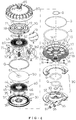
FIG. 4 includes an exploded perspective view, and locally enlarged views taken along circles "A", "K" and "G", of the hydrogen molecule remixing device in accordance with the preferred embodiment of the present invention. -
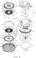
FIG. 5 includes an exploded perspective view and a locally enlarged view taken along circle "S", of the hydrogen molecule remixing device in accordance with the preferred embodiment of the present invention. -
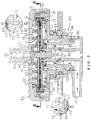
FIG. 6 is a cross-sectional view of the hydrogen molecule remixing device in accordance with the preferred embodiment of the present invention. -
FIG. 7 includes a cross-sectional view, and locally enlarged views taken along circles "C" and "Y", of the hydrogen molecule remixing device in accordance with the preferred embodiment of the present invention. -
FIG. 8 is a cross-sectional view of the hydrogen molecule remixing device taken along line E-E as shown inFIG. 7 . -
FIG. 9 is another cross-sectional view of the hydrogen molecule remixing device in accordance with the preferred embodiment of the present invention. -
FIG. 10 is a cross-sectional view of the hydrogen molecule remixing device taken along line J-J as shown inFIG. 9 . -
FIG. 11 is a cross-sectional view of the hydrogen molecule remixing device taken along line F-F as shown inFIG. 9 . -
FIG. 12 is a cross-sectional view of the hydrogen molecule remixing device taken along line R-R as shown inFIG. 9 . -
FIG. 13 is an exploded perspective view of a hydrogen molecule remixing device in accordance with another preferred embodiment of the present invention. -
FIG. 14 includes a cross-sectional view, and a locally enlarged view taken along circle "H", of the hydrogen molecule remixing device in accordance with another preferred embodiment of the present invention. - Referring to the drawings and initially to
FIGS. 1-6 , a hydrogen molecule remixing device in accordance with the preferred embodiment of the present invention comprises abase 10, a first gas andwater channelling disc 30 located above thebase 10, ananode 40 located above the first gas and water channellingdisc 30, acathode 60 located above theanode 40, anion membrane 50 located between theanode 40 and thecathode 60, a second gas andwater channelling disc 70 located above thecathode 60, acover 80 combined with thebase 10 and located above the second gas andwater channelling disc 70, a cationicwater outlet connector 85 extending upward from thecover 80, and aconnector 90 extending downward from thebase 10. - The
base 10 and thecover 80 have a disk shape. The first gas andwater channelling disc 30, theanode 40, theion membrane 50, thecathode 60 and the second gas and waterchannelling disc 70 are arranged between thebase 10 and thecover 80. - The first gas and water channelling
disc 30 has a disk shape and is provided with a first collecting and guidingchamber 391 corresponding to thebase 10. - The second gas and water channelling
disc 70 has a disk shape and is provided with a plurality of second collecting and guidingchambers 78 corresponding to thecover 80. - The
anode 40 has a disk shape and is provided with a plurality of firstwater inlet ports 43 and a plurality ofanode cavities 42. Theanode cavities 42 are arranged in a radiating manner. The source water is guided through the firstwater inlet ports 43 into theanode cavities 42 of theanode 40. - The
cathode 60 has a disk shape and is provided with a plurality of secondwater inlet ports 63 and a plurality ofcathode cavities 62. Thecathode cavities 62 are arranged in a radiating manner. The shape, size and position of thecathode cavities 62 of thecathode 60 are the same as that of theanode cavities 42 of theanode 40. The source water is guided through the secondwater inlet ports 63 into thecathode cavities 62 of thecathode 60. - The
connector 90 is provided with a source water input joint 97 and an anionicwater output joint 96. Theconnector 90 includes a sourcewater inlet chamber 95 and an anionicwater exit chamber 94. The sourcewater inlet chamber 95 has a diameter smaller than that of the anionicwater exit chamber 94. The source water input joint 97 is connected to and protrudes from the sourcewater inlet chamber 95, and the anionic water output joint 96 is connected to and protrudes from the anionicwater exit chamber 94. The anionic water output joint 96 is connected with a anionic water outlet hose (not shown). - In practice, the source water is respectively guided through the first
water inlet ports 43 of theanode 40 and the secondwater inlet ports 63 of thecathode 60 into theanode cavities 42 of theanode 40 and thecathode cavities 62 of thecathode 60. The source water is a solution that has not been electrolyzed. The source water is electrolyzed in theanode cavities 42 of theanode 40 to form oxygen molecules, ozone and anionic water, and is electrolyzed in thecathode cavities 62 of thecathode 60 to form hydrogen molecules and cationic water. The oxygen molecules and ozone in theanode cavities 42 of theanode 40 are carried by the anionic water into the first collecting and guidingchamber 391 of the first gas andwater channelling disc 30. The hydrogen molecules in thecathode cavities 62 of thecathode 60 are carried by the cationic water into the second collecting and guidingchambers 78 of the second gas andwater channelling disc 70, so that the hydrogen molecules and the cationic water produce an blending reaction in the second collecting and guidingchambers 78, and more hydrogen molecules are dissolved into the cationic water, to increase the concentration of the hydrogen molecules in the cationic water. - In the preferred embodiment of the present invention, polarities of the
anode 40 and thecathode 60 are interchanged. - In the preferred embodiment of the present invention, the
base 10 has a top provided with a plurality ofpartitions 12 which are arranged in a radiating manner, and a plurality of anionicwater flow paths 121 located between thepartitions 12. Thebase 10 is provided with aconductive spacing tube 14, afirst spacing ring 15 surrounding theconductive spacing tube 14, and asecond spacing ring 16 surrounding thefirst spacing ring 15. Thebase 10 is provided with a plurality of first spacing ribs 151 located between thefirst spacing ring 15 and theconductive spacing tube 14 and forming a plurality of sourcewater inlet paths 152 in thefirst spacing ring 15, and a plurality of second spacing ribs 161 located between thesecond spacing ring 16 and thefirst spacing ring 15 and forming a plurality of anionicwater outlet paths 162 in thesecond spacing ring 16. Thesecond spacing ring 16 is provided with a plurality of anionicwater outlet ports 163 corresponding to the anionicwater flow paths 121. The anionicwater outlet paths 162 have a bottom provided with a plurality of anionic water outlet holes 164. - In the preferred embodiment of the present invention, the top of the
base 10 is provided with anannular flange 17 surrounding thepartitions 12, and a connectinggroove 171 is formed between an inner wall of thebase 10 and theannular flange 17 for connecting the first gas andwater channelling disc 30. The first gas andwater channelling disc 30 has an outer wall provided with anannular groove 37 corresponding to the connectinggroove 171 of thebase 10, and an O-ring "Q" is compressed between the connectinggroove 171 of thebase 10 and theannular groove 37 of the first gas andwater channelling disc 30, to prevent the cationic water and the anionic water from being mixed. - In the preferred embodiment of the present invention, the
base 10 is provided with a mounting protrusion 11 extending downward for mounting theconnector 90. The mounting protrusion 11 of thebase 10 is provided with at least onetenon 112. Theconnector 90 is provided with a mountingrecess 92 mounted on the mounting protrusion 11 of thebase 10. The mountingrecess 92 of theconnector 90 is provided with at least onemortise 93 locked onto thetenon 112 of the mounting protrusion 11 by rotation, so that theconnector 90 is locked onto or unlocked from the base 10 quickly. The mounting protrusion 11 of thebase 10 is provided with twogrooves 111 for mounting two O-rings "Q". The anionic water outlet holes 164 correspond to a periphery of the mounting protrusion 11. - In the preferred embodiment of the present invention, the
base 10 is provided with anexternal thread 18, and thecover 80 is provided with aninternal thread 81 screwed onto theexternal thread 18 of thebase 10. Thebase 10 is provided with anannular groove 19 located above theexternal thread 18, and an O-ring "Q" is retained in theannular groove 19 of thebase 10 and compressed between the base 10 and thecover 80. - In the preferred embodiment of the present invention, the
anode 40 has a periphery provided with a plurality offirst positioning portions 44, and thecathode 60 has a periphery provided with a plurality ofsecond positioning portions 64 located on thefirst positioning portions 44 of theanode 40 to align theanode cavities 42 of theanode 40 with thecathode cavities 62 of thecathode 60, so that theanode 40 aligns with thecathode 60. - In the preferred embodiment of the present invention, the
cover 80 is provided with a plurality offirst stop flanges 82 forming a plurality ofhydrogen dissolving chambers 83 in thecover 80, and the second gas andwater channelling disc 70 is provided with a plurality ofsecond stop flanges 77 forming the second collecting and guidingchambers 78 in the second gas andwater channelling disc 70. Thefirst stop flanges 82 of thecover 80 and thesecond stop flanges 77 of the second gas andwater channelling disc 70 have an annular shape and are arranged alternatingly. Each of thefirst stop flanges 82 of thecover 80 is provided with a plurality offirst openings 84 to collect the hydrogen molecules and guide the cationic water, and each of thesecond stop flanges 77 of the second gas andwater channelling disc 70 is provided with a plurality ofsecond openings 79 to collect the hydrogen molecules and guide the cationic water, so as to rapidly receive the hydrogen molecules produced by thecathode 60. In such a manner, the cationic water is moved upward and downward in the second collecting and guidingchambers 78 of the second gas andwater channelling disc 70 and thehydrogen dissolving chambers 83 of thecover 80 to present a substantially successive S-shaped flow. Thus, the hydrogen molecules are lifted, and the cationic water is lowered to produce an blending reaction, so that more hydrogen molecules are dissolved into the cationic water. - In the preferred embodiment of the present invention, the
ion membrane 50 is a proton exchange film and has a diameter greater than that of theanode 40 and that of thecathode 60. The first gas andwater channelling disc 30 is provided with a protrudingring 362, the second gas andwater channelling disc 70 is provided with aslot 72 mounted on the protrudingring 362 of the first gas andwater channelling disc 30, and an O-ring "Q" is compressed between the protrudingring 362 of the first gas andwater channelling disc 30 and theslot 72 of the second gas andwater channelling disc 70, so that theion membrane 50 is compressed by the protrudingring 362 of the first gas andwater channelling disc 30 and the O-ring "Q", so as to stop a water flow, thereby preventing the cationic water and the anionic water from being mixed. - In the preferred embodiment of the present invention, the first gas and
water channelling disc 30 has a periphery provided with a plurality of locatingslots 35, and the second gas andwater channelling disc 70 has a periphery provided with a plurality of locatinginserts 71 inserted into the locatingslots 35 of the first gas andwater channelling disc 30, so that the second gas andwater channelling disc 70 is positioned on the first gas andwater channelling disc 30. - In the preferred embodiment of the present invention, an
electric conductor 20 is mounted on thecathode 60 and connected with thebase 10. Theelectric conductor 20 has a lower end provided with a conductingportion 26 locked in theconductive spacing tube 14 of thebase 10. Thebase 10 is provided with two throughholes 13, and theanode 40 is provided with twopositive conducting portions 45 extending through the two throughholes 13 of thebase 10 and locked by two washers "R" and two nuts "N". Each of the twopositive conducting portions 45 of theanode 40 is provided with anouter thread 46 extending through one of the two washers "R" and screwed by one of the two nuts "N". Theconnector 90 is provided with ahollow pillar 91 corresponding to theconductive spacing tube 14 of thebase 10, anegative conducting shaft 98 is movably mounted in thehollow pillar 91 and connected to a negative wire (not shown), and an elastic member "S" is mounted in thehollow pillar 91 and biased between thehollow pillar 91 and thenegative conducting shaft 98 to push thenegative conducting shaft 98 to closely contact the conductingportion 26 of theelectric conductor 20. Theconnector 90 is provided with two elasticpositive conducting blades 99 corresponding to and closely contacting the twopositive conducting portions 45 of theanode 40 and connected to a positive wire (not shown). - In the preferred embodiment of the present invention, the
anode cavities 42 of theanode 40 and thecathode cavities 62 of thecathode 60 have a substantially V-shaped configuration. - In the preferred embodiment of the present invention, the first gas and
water channelling disc 30 is provided with a first sourcewater inlet passage 34 corresponding to the firstwater inlet ports 43 of theanode 40, and the second gas andwater channelling disc 70 is provided with a second sourcewater inlet passage 74 corresponding to the secondwater inlet ports 63 of thecathode 60. The first gas andwater channelling disc 30 is provided with a plurality of anionicwater outlet ports 36 and a plurality of anionicwater outlet channels 361, and the second gas andwater channelling disc 70 is provided with a plurality of cationicwater outlet ports 75 and a plurality of cationicwater outlet channels 76. The source water flows through the firstwater inlet ports 43 of theanode 40 into the first sourcewater inlet passage 34 of the first gas andwater channelling disc 30, and flows from the firstwater inlet ports 43 of theanode 40 into theanode cavities 42 of theanode 40 in a radiating manner, and finally flows out of the anionicwater outlet channels 361 and the anionicwater outlet ports 36 of the first gas andwater channelling disc 30. The source water also flows through the secondwater inlet ports 63 of thecathode 60 into the second sourcewater inlet passage 74 of the second gas andwater channelling disc 70, and flows outward from the secondwater inlet ports 63 of thecathode 60 into thecathode cavities 62 of thecathode 60 in a radiating manner, and finally flows out of the cationicwater outlet channels 76 and the cationicwater outlet ports 75 of the second gas andwater channelling disc 70. - In the preferred embodiment of the present invention, the first gas and
water channelling disc 30 is provided with anannular stop edge 39 corresponding to thebase 10 and forming the collecting and guidingspace 391 between the base 10 and the first gas andwater channelling disc 30, to collect the oxygen molecules and ozone and guide the anionic water, so as to rapidly receive the oxygen molecules and ozone produced by theanode 40, thereby preventing the oxygen molecules and ozone from being mixed with the cationic water. - In the preferred embodiment of the present invention, the first gas and
water channelling disc 30 is provided with anannular projection 38 corresponding to the anionicwater outlet ports 36 to lift a level of the anionic water, so that theion membrane 50 is wet fully. - In the preferred embodiment of the present invention, the
conductive spacing tube 14 of thebase 10 is provided with aninternal thread 141, and the lower end of theelectric conductor 20 is provided with a lower steppededge 24 located in theconductive spacing tube 14 of thebase 10 and anexternal thread 23 screwed into theinternal thread 141 of theconductive spacing tube 14. Thecathode 60 has a center provided with ashaft hole 61, with the secondwater inlet ports 63 being located between theshaft hole 61 and thecathode cavities 62. Theelectric conductor 20 has an upper end provided with an upper steppededge 22 resting on thecathode 60 and anouter thread 21 extending through an O-ring "Q" and theshaft hole 61 of thecathode 60, and a nut "N" is screwed onto theouter thread 21 of theelectric conductor 20 to lock thecathode 60 onto theelectric conductor 20. Theelectric conductor 20 is provided with anannular groove 25 located between the upper steppededge 22 and the lower steppededge 24, and an O-ring "Q" is retained in theannular groove 25 of theelectric conductor 20 and compressed between theconductive spacing tube 14 of thebase 10 and theelectric conductor 20. The second gas andwater channelling disc 70 has a bottom provided with a receivingrecess 73 for receiving the nut "N" and theouter thread 21 of theelectric conductor 20. - In the preferred embodiment of the present invention, the first gas and
water channelling disc 30 is provided with twohollow posts 31 extending through the two throughholes 13 of thebase 10. Each of the twohollow posts 31 is provided with anaperture 311 allowing passage of each of the twopositive conducting portions 45 of theanode 40. Theaperture 311 of each of the twohollow posts 31 receives an O-ring "Q" to provide a water stop function. The first gas andwater channelling disc 30 has a center provided with aspacing sleeve 32 which has an outer wall provided with a plurality of sourcewater inlet ports 33, and the first sourcewater inlet passage 34 are formed on a periphery of the sourcewater inlet ports 33. Thus, the source water flows through the sourcewater inlet ports 33 into the first sourcewater inlet passage 34, and then flows outward from the first sourcewater inlet passage 34 in a radiating manner. Thespacing sleeve 32 of the first gas andwater channelling disc 30 has a lower end provided with anannular groove 321 corresponding to thefirst spacing ring 15 of thebase 10, and an O-ring "Q" is retained in theannular groove 321 of the first gas andwater channelling disc 30. - In the preferred embodiment of the present invention, the
anode 40 has a center provided with ashaft hole 41 having a diameter flush with that of thespacing sleeve 32 of the first gas andwater channelling disc 30, and theion membrane 50 has a center provided with ashaft hole 51 having a diameter flush with that of thespacing sleeve 32 of the first gas andwater channelling disc 30. The hydrogen molecules permeate theion membrane 50, and the oxygen molecules cannot permeate theion membrane 50 during the electrolysis process, thereby preventing the oxygen molecules and ozone produced by theanode 40 from being mixed with the cationic water. - In the preferred embodiment of the present invention, the cationic
water outlet connector 85 is connected with a cationic water outlet hose (not shown) so that the cationic water is delivered through the cationicwater outlet connector 85 and carried outward from the cationic water outlet hose. The cationicwater outlet connector 85 is provided with anannular groove 86, and an O-ring "Q" is retained in theannular groove 86 of the cationicwater outlet connector 85 and compressed between the cationicwater outlet connector 85 and the cationic water outlet hose. - In operation, referring to
FIGS. 7 and8 with reference toFIGS. 1-6 , the source water in turn flows through the source water input joint 97 and the sourcewater inlet chamber 95 into the sourcewater inlet paths 152 of thefirst spacing ring 15. Then, most of the source water flows through the secondwater inlet ports 63 of thecathode 60 into the second sourcewater inlet passage 74 of the second gas andwater channelling disc 70, and flows into thecathode cavities 62 of thecathode 60 in a radiating manner. At the same time, a small part of the source water flows through the sourcewater inlet ports 33 into the first sourcewater inlet passage 34 of theanode 40, and then flows through the firstwater inlet ports 43 into theanode cavities 42 of theanode 40. - Referring to
FIGS. 9-12 with reference toFIGS. 1-8 , the source water is electrolyzed in theanode cavities 42 of theanode 40 to form oxygen molecules, ozone and anionic water, and is electrolyzed in thecathode cavities 62 of thecathode 60 to form hydrogen molecules and cationic water. At this time, theion membrane 50 is located between theanode 40 and thecathode 60, so that the hydrogen molecules permeate theion membrane 50, and the oxygen molecules cannot permeate theion membrane 50 during the electrolysis process, thereby preventing the oxygen molecules and ozone produced by theanode 40 from being mixed with the cationic water. - The hydrogen molecules produced in the
cathode cavities 62 of thecathode 60 are carried by the cationic water to flow through the cationicwater outlet channels 76, the cationicwater outlet ports 75 and thesecond openings 79 of thesecond stop flanges 77 into the second collecting and guidingchambers 78, so that the hydrogen molecules are collected in thehydrogen dissolving chambers 83. At the same time, the cationic water is moved upward and downward in the second collecting and guidingchambers 78 of the second gas andwater channelling disc 70 and thehydrogen dissolving chambers 83 of thecover 80 to present a substantially successive S-shaped flow. Thus, the hydrogen molecules are lifted, and the cationic water is lowered to produce an blending reaction, so that more hydrogen molecules are dissolved into the cationic water. In addition, more hydrogen molecules are forced by the pressure and dissolved again into the cationic water, thereby increasing the concentration of the hydrogen molecules in the cationic water. Finally, the cationic water containing the hydrogen molecules is delivered through the cationicwater outlet connector 85 and drained outward from the cationic water outlet hose. - The oxygen molecules and ozone produced in the
anode cavities 42 of theanode 40 are carried by the anionic water to flow through the anionicwater outlet channels 361, the anionicwater outlet ports 36 and thestop edge 39 into the first collecting and guidingchamber 391 of the first gas andwater channelling disc 30, so that the oxygen molecules and ozone are collected in the first collecting and guidingchamber 391, thereby preventing the oxygen molecules and ozone from being mixed with the cationic water. Finally, the anionic water containing the oxygen molecules and ozone is delivered through the anionicwater exit chamber 94 and the anionicwater output joint 96 of theconnector 90 and drained outward from the anionic water outlet hose. At this time, theannular projection 38 of the first gas andwater channelling disc 30 lifts the level of the anionic water, so that theion membrane 50 is wet fully. - Referring to
FIGS. 13 and14 , theanode cavities 42 of theanode 40 and thecathode cavities 62 of thecathode 60 include multiple holes. The first gas andwater channelling disc 30 is provided with a plurality offirst spacing pieces 341 corresponding to theanode cavities 42 of theanode 40, and a plurality of anionicwater flow channels 342 located between thefirst spacing pieces 341, so that the oxygen molecules and ozone produced in theanode cavities 42 of theanode 40 are rapidly carried away by the anionic water. Thefirst spacing pieces 341 are arranged in a radiating manner. The second gas andwater channelling disc 70 is provided with a plurality ofsecond spacing pieces 741 corresponding to thecathode cavities 62 of thecathode 60, and a plurality of cationicwater flow channels 742 located between thesecond spacing pieces 741, so that the hydrogen molecules produced in thecathode cavities 62 of thecathode 60 are rapidly carried away by the cationic water. Thesecond spacing pieces 741 are arranged in a radiating manner. - Accordingly, more hydrogen molecules are dissolved into the cationic water by the blending reaction in the
hydrogen dissolving chambers 83 of thecover 80 and by the increased pressure, so as to increase the concentration of the hydrogen molecules in the cationic water. In addition, thecathode cavities 62 of thecathode 60 are arranged in a radiating manner to form multiple cationic water flow channels, so that the hydrogen molecules produced in thecathode cavities 62 of thecathode 60 are quickly carried away by the cationic water, thereby preventing the hydrogen molecules from producing larger air bubbles due to a reunion phenomenon, so as to efficiently enhance the dissolved quantity (or solubility) of the hydrogen molecules. Further, the first collecting and guidingchamber 391 of the first gas andwater channelling disc 30 corresponds to theanode 40 to rapidly collect the oxygen molecules and ozone produced by theanode 40, thereby preventing the oxygen molecules and ozone from being mixed with the cationic water. Further, the concentration of the hydrogen molecules in the cationic water is increased by more than 30%. Further, thehydrogen dissolving chambers 83, the first collecting and guidingchamber 391 and the second collecting and guidingchambers 78 are integrated and modularized, thereby decreasing the cost of fabrication. Further, the hydrogen molecule remixing device is assembled and disassembled quickly.
Claims (17)
- A hydrogen molecule remixing method comprising:guiding source water respectively through first water inlet ports of an anode and second water inlet ports of a cathode into anode cavities of the anode and cathode cavities of the cathode;electrolyzing the source water in the anode cavities of the anode to form oxygen molecules, ozone and anionic water, and electrolyzing the source water in the cathode cavities of the cathode to form hydrogen molecules and cationic water;blending the hydrogen molecules with the cationic water;providing an ion membrane between the anode and the cathode to prevent the oxygen molecules from being mixed in the cationic water;the anionic water carrying the oxygen molecules and ozone from the anode cavities of the anode into a first collecting and guiding chamber of a first gas and water channelling disc; andthe cationic water carrying the hydrogen molecules from the cathode cavities of the cathode into second collecting and guiding chambers of a second gas and water channelling disc, with the hydrogen molecules and the cationic water producing an blending reaction in the second collecting and guiding chambers, forcing more hydrogen molecules to be dissolved again into the cationic water, to increase a concentration of the hydrogen molecules in the cationic water.
- A hydrogen molecule remixing device comprising:a base (10);a first gas and water channelling disc (30) located above the base;an anode (40) located above the first gas and water channelling disc;a cathode (60) located above the anode;an ion membrane (50) located between the anode and the cathode;a second gas and water channelling disc (70) located above the cathode;a cover (80) combined with the base and located above the second gas and water channelling disc;a cationic water outlet connector (85) extending upward from the cover; anda connector (90) extending downward from the base;wherein:the first gas and water channelling disc is provided with a first collecting and guiding chamber (391) corresponding to the base;the second gas and water channelling disc is provided with a plurality of second collecting and guiding chambers (78) corresponding to the cover (80);the anode is provided with a plurality of first water inlet ports (43) and a plurality of anode cavities (42);the anode cavities are arranged in a radiating manner;the cathode is provided with a plurality of second water inlet ports (63) and a plurality of cathode cavities (62);the cathode cavities are arranged in a radiating manner;the connector is provided with a source water input joint (97) and an anionic water output joint (96);source water is respectively guided through the first water inlet ports of the anode and the second water inlet ports of the cathode into the anode cavities of the anode and the cathode cavities of the cathode;the source water is electrolyzed in the anode cavities of the anode to form oxygen molecules, ozone and anionic water, and is electrolyzed in the cathode cavities of the cathode to form hydrogen molecules and cationic water;the oxygen molecules and ozone in the anode cavities of the anode are carried by the anionic water into the first collecting and guiding chamber of the first gas and water channelling disc; andthe hydrogen molecules in the cathode cavities of the cathode are carried by the cationic water into the second collecting and guiding chambers of the second gas and water channelling disc, so that the hydrogen molecules and the cationic water produce an blending reaction in the second collecting and guiding chambers, and more hydrogen molecules are dissolved into the cationic water, to increase a concentration of the hydrogen molecules in the cationic water.
- The hydrogen molecule remixing device of claim 2, wherein polarities of the anode and the cathode are interchanged.
- The hydrogen molecule remixing device of claim 2, wherein:the base has a top provided with a plurality of partitions (12) which are arranged in a radiating manner, and a plurality of anionic water flow paths (121) located between the partitions;the base is provided with a conductive spacing tube (14), a first spacing ring (15) surrounding the conductive spacing tube, and a second spacing ring (16) surrounding the first spacing ring;the base is provided with a plurality of first spacing ribs (151) located between the first spacing ring and the conductive spacing tube and forming a plurality of source water inlet paths (152) in the first spacing ring, and a plurality of second spacing ribs (161) located between the second spacing ring and the first spacing ring and forming a plurality of anionic water outlet paths (162) in the second spacing ring;the second spacing ring is provided with a plurality of anionic water outlet ports (163) corresponding to the anionic water flow paths; andthe anionic water outlet paths have a bottom provided with a plurality of anionic water outlet holes (164).
- The hydrogen molecule remixing device of claim 2, wherein:the top of the base is provided with an annular flange (17) surrounding the partitions, and a connecting groove (171) is formed between an inner wall of the base and the annular flange for connecting the first gas and water channelling disc;the first gas and water channelling disc has an outer wall provided with an annular groove (37) corresponding to the connecting groove of the base; andan O-ring (Q) is compressed between the connecting groove of the base and the annular groove of the first gas and water channelling disc.
- The hydrogen molecule remixing device of claim 2, wherein:the base is provided with a mounting protrusion (11) extending downward;the mounting protrusion of the base is provided with at least one tenon (112);the connector is provided with a mounting recess (92) mounted on the mounting protrusion of the base; andthe mounting recess of the connector is provided with at least one mortise (93) locked onto the tenon of the mounting protrusion.
- The hydrogen molecule remixing device of claim 2, wherein the base is provided with an external thread (18), and the cover is provided with an internal thread (81) screwed onto the external thread of the base.
- The hydrogen molecule remixing device of claim 2, wherein the anode has a periphery provided with a plurality of first positioning portions (44), and the cathode has a periphery provided with a plurality of second positioning portions (64) located on the first positioning portions of the anode to align the anode cavities of the anode with the cathode cavities of the cathode.
- The hydrogen molecule remixing device of claim 2, wherein:the cover is provided with a plurality of first stop flanges (82) forming a plurality of hydrogen dissolving chambers (83) in the cover;the second gas and water channelling disc is provided with a plurality of second stop flanges (77) forming the second collecting and guiding chambers in the second gas and water channelling disc;each of the first stop flanges of the cover is provided with a plurality of first openings (84) to collect the hydrogen molecules and guide the cationic water;each of the second stop flanges of the second gas and water channelling disc is provided with a plurality of second openings (79) to collect the hydrogen molecules and guide the cationic water; andthe cationic water is moved upward and downward in the second collecting and guiding chambers of the second gas and water channelling disc and the hydrogen dissolving chambers of the cover to present a substantially successive S-shaped flow.
- The hydrogen molecule remixing device of claim 2, wherein:the ion membrane is a proton exchange film and has a diameter greater than that of the anode and that of the cathode;the first gas and water channelling disc is provided with a protruding ring (362);the second gas and water channelling disc is provided with a slot (72) mounted on the protruding ring of the first gas and water channelling disc; andan O-ring is compressed between the protruding ring of the first gas and water channelling disc and the slot of the second gas and water channelling disc.
- The hydrogen molecule remixing device of claim 2, wherein the first gas and water channelling disc has a periphery provided with a plurality of locating slots (35), and the second gas and water channelling disc has a periphery provided with a plurality of locating inserts (71) inserted into the locating slots of the first gas and water channelling disc.
- The hydrogen molecule remixing device of claim 2, wherein:an electric conductor (20) is mounted on the cathode and connected with the base;the electric conductor has a lower end provided with a conducting portion (26) mounted in a conductive spacing tube (14) of the base;the base is provided with two through holes 13;the anode is provided with two positive conducting portions (45) extending through the two through holes of the base;the connector is provided with a hollow pillar (91) corresponding to the conductive spacing tube of the base;a negative conducting shaft (98) is movably mounted in the hollow pillar and connected to a negative wire;an elastic member (S) is mounted in the hollow pillar and biased between the hollow pillar and the negative conducting shaft to push the negative conducting shaft to closely contact the conducting portion of the electric conductor; andthe connector is provided with two elastic positive conducting blades (99) corresponding to the two positive conducting portions of the anode and connected to a positive wire.
- The hydrogen molecule remixing device of claim 2, wherein the anode cavities of the anode and the cathode cavities of the cathode have a substantially V-shaped configuration.
- The hydrogen molecule remixing device of claim 2, wherein:the anode cavities of the anode and the cathode cavities of the cathode include multiple holes;the first gas and water channelling disc is provided with a plurality of first spacing pieces (341) corresponding to the anode cavities of the anode, and a plurality of anionic water flow channels (342) located between the first spacing pieces;the first spacing pieces are arranged in a radiating manner;the second gas and water channelling disc is provided with a plurality of second spacing pieces (741) corresponding to the cathode cavities of the cathode, and a plurality of cationic water flow channels (742) located between the second spacing pieces; andthe second spacing pieces are arranged in a radiating manner.
- The hydrogen molecule remixing device of claim 2, wherein:the first gas and water channelling disc is provided with a first source water inlet passage (34) corresponding to the first water inlet ports of the anode;the second gas and water channelling disc is provided with a second source water inlet passage (74) corresponding to the second water inlet ports of the cathode;the first gas and water channelling disc is provided with a plurality of anionic water outlet ports (36) and a plurality of anionic water outlet channels (361);the second gas and water channelling disc is provided with a plurality of cationic water outlet ports (75) and a plurality of cationic water outlet channels (76);the source water flows through the first water inlet ports of the anode into the first source water inlet passage of the first gas and water channelling disc, and flows from the first water inlet ports of the anode into the anode cavities of the anode in a radiating manner, and finally flows out of the anionic water outlet channels and the anionic water outlet ports of the first gas and water channelling disc; andthe source water flows through the second water inlet ports of the cathode into the second source water inlet passage of the second gas and water channelling disc, and flows outward from the second water inlet ports of the cathode into the cathode cavities of the cathode in a radiating manner, and finally flows out of the cationic water outlet channels and the cationic water outlet ports of the second gas and water channelling disc.
- The hydrogen molecule remixing device of claim 15, wherein the first gas and water channelling disc is provided with an annular stop edge (39) corresponding to the base and forming the collecting and guiding space between the base and the first gas and water channelling disc, to collect the oxygen molecules and ozone and guide the anionic water.
- The hydrogen molecule remixing device of claim 15, wherein the first gas and water channelling disc is provided with an annular projection (38) corresponding to the anionic water outlet ports.
Priority Applications (2)
| Application Number | Priority Date | Filing Date | Title |
|---|---|---|---|
| EP18173312.2A EP3569738B1 (en) | 2018-05-18 | 2018-05-18 | Hydrogen molecule remixing device of dish-shaped electrolytic cell |
| ES18173312T ES2799878T3 (en) | 2018-05-18 | 2018-05-18 | Disc Shape Electrolytic Cell Hydrogen Molecule Remixing Device |
Applications Claiming Priority (1)
| Application Number | Priority Date | Filing Date | Title |
|---|---|---|---|
| EP18173312.2A EP3569738B1 (en) | 2018-05-18 | 2018-05-18 | Hydrogen molecule remixing device of dish-shaped electrolytic cell |
Publications (2)
| Publication Number | Publication Date |
|---|---|
| EP3569738A1 true EP3569738A1 (en) | 2019-11-20 |
| EP3569738B1 EP3569738B1 (en) | 2020-04-01 |
Family
ID=62217873
Family Applications (1)
| Application Number | Title | Priority Date | Filing Date |
|---|---|---|---|
| EP18173312.2A Active EP3569738B1 (en) | 2018-05-18 | 2018-05-18 | Hydrogen molecule remixing device of dish-shaped electrolytic cell |
Country Status (2)
| Country | Link |
|---|---|
| EP (1) | EP3569738B1 (en) |
| ES (1) | ES2799878T3 (en) |
Cited By (1)
| Publication number | Priority date | Publication date | Assignee | Title |
|---|---|---|---|---|
| US10774432B2 (en) * | 2018-05-16 | 2020-09-15 | Wen-Shing Shyu | Hydrogen molecule remixing device of dish-shaped electrolytic cell |
Citations (6)
| Publication number | Priority date | Publication date | Assignee | Title |
|---|---|---|---|---|
| US6056858A (en) * | 1996-03-28 | 2000-05-02 | Siemens Aktiengesellschaft | Gasification device |
| TW200909612A (en) * | 2007-08-31 | 2009-03-01 | wen-xing Xu | Radiation type electrolysis device |
| US20110008736A1 (en) * | 2007-11-02 | 2011-01-13 | Yusho Arai | Combustion system,combustion method, fuel fluid, process for producing the fuel fluid, and apparatus for producing the fuel fluid |
| US20120031754A1 (en) * | 2007-09-11 | 2012-02-09 | Wen-Shing Shyu | Electrolyzer having radial flowing passage |
| CN106365260A (en) * | 2016-09-30 | 2017-02-01 | 广州市康亦健医疗设备有限公司 | Hydrogen-rich water electrolytic bath |
| US20180037480A1 (en) * | 2016-08-02 | 2018-02-08 | Miz Company Limited | Method for producing hydrogen water |
-
2018
- 2018-05-18 ES ES18173312T patent/ES2799878T3/en active Active
- 2018-05-18 EP EP18173312.2A patent/EP3569738B1/en active Active
Patent Citations (6)
| Publication number | Priority date | Publication date | Assignee | Title |
|---|---|---|---|---|
| US6056858A (en) * | 1996-03-28 | 2000-05-02 | Siemens Aktiengesellschaft | Gasification device |
| TW200909612A (en) * | 2007-08-31 | 2009-03-01 | wen-xing Xu | Radiation type electrolysis device |
| US20120031754A1 (en) * | 2007-09-11 | 2012-02-09 | Wen-Shing Shyu | Electrolyzer having radial flowing passage |
| US20110008736A1 (en) * | 2007-11-02 | 2011-01-13 | Yusho Arai | Combustion system,combustion method, fuel fluid, process for producing the fuel fluid, and apparatus for producing the fuel fluid |
| US20180037480A1 (en) * | 2016-08-02 | 2018-02-08 | Miz Company Limited | Method for producing hydrogen water |
| CN106365260A (en) * | 2016-09-30 | 2017-02-01 | 广州市康亦健医疗设备有限公司 | Hydrogen-rich water electrolytic bath |
Cited By (1)
| Publication number | Priority date | Publication date | Assignee | Title |
|---|---|---|---|---|
| US10774432B2 (en) * | 2018-05-16 | 2020-09-15 | Wen-Shing Shyu | Hydrogen molecule remixing device of dish-shaped electrolytic cell |
Also Published As
| Publication number | Publication date |
|---|---|
| ES2799878T3 (en) | 2020-12-22 |
| EP3569738B1 (en) | 2020-04-01 |
Similar Documents
| Publication | Publication Date | Title |
|---|---|---|
| CN102123953B (en) | Tubular electrolysis cell comprising concentric electrodes and corresponding method | |
| US10774432B2 (en) | Hydrogen molecule remixing device of dish-shaped electrolytic cell | |
| US8057646B2 (en) | Electrolyser and components therefor | |
| US4033848A (en) | Wafer electrode for an electrolytic cell | |
| US20220112615A1 (en) | Ozone generator for a faucet | |
| US20120031754A1 (en) | Electrolyzer having radial flowing passage | |
| KR101575164B1 (en) | Apparatus for manufacturing ionic water | |
| TWI654144B (en) | Ozone water manufacturing equipment | |
| KR101695675B1 (en) | Module for manufacturing ionic water | |
| US20050199546A1 (en) | Separator for removing liquid from fluid | |
| JP2016035099A (en) | Hydrogen generation unit for producing hydrogen water | |
| JP6986192B2 (en) | Electrode assembly, electrode structure and electrolytic cell | |
| KR101896263B1 (en) | Manufacturing apparatus of hydrogen water | |
| EP3569738B1 (en) | Hydrogen molecule remixing device of dish-shaped electrolytic cell | |
| AU2019204021B1 (en) | Hydrogen molecule remixing device of dish-shaped electrolytic cell | |
| JP6731443B2 (en) | Method and device for re-dissolving hydrogen molecules in disk type electrolytic cell | |
| KR101284643B1 (en) | Electrolytic cell for flow throuth-continuous deionization | |
| KR101739123B1 (en) | A cartridge for creating sterilized water having bypass | |
| KR20140028495A (en) | Cartridge for creating sterilized water having hloe for inserting and taking out water in one direction | |
| JP5868630B2 (en) | Electrolyzed water production apparatus and electrolyzed water production method | |
| CN110396697B (en) | Hydrogen molecule re-fusion method and device for disk type electrolytic cell | |
| US7833390B2 (en) | Electrolyzer having radial flowing passage | |
| CN101054682B (en) | Horizontal radiation type electrolysis method and device | |
| KR102028038B1 (en) | Hydrogenated electrolytic cell with nano bubble nozzle | |
| WO2015038771A1 (en) | Devices and methods for water desalination |
Legal Events
| Date | Code | Title | Description |
|---|---|---|---|
| STAA | Information on the status of an ep patent application or granted ep patent |
Free format text: STATUS: EXAMINATION IS IN PROGRESS |
|
| PUAI | Public reference made under article 153(3) epc to a published international application that has entered the european phase |
Free format text: ORIGINAL CODE: 0009012 |
|
| 17P | Request for examination filed |
Effective date: 20180518 |
|
| AK | Designated contracting states |
Kind code of ref document: A1 Designated state(s): AL AT BE BG CH CY CZ DE DK EE ES FI FR GB GR HR HU IE IS IT LI LT LU LV MC MK MT NL NO PL PT RO RS SE SI SK SM TR |
|
| AX | Request for extension of the european patent |
Extension state: BA ME |
|
| GRAP | Despatch of communication of intention to grant a patent |
Free format text: ORIGINAL CODE: EPIDOSNIGR1 |
|
| STAA | Information on the status of an ep patent application or granted ep patent |
Free format text: STATUS: GRANT OF PATENT IS INTENDED |
|
| RIC1 | Information provided on ipc code assigned before grant |
Ipc: C25B 1/10 20060101AFI20191119BHEP Ipc: C25B 9/08 20060101ALI20191119BHEP Ipc: C02F 1/461 20060101ALI20191119BHEP Ipc: C25B 15/08 20060101ALI20191119BHEP Ipc: C02F 1/467 20060101ALI20191119BHEP Ipc: C25B 1/13 20060101ALI20191119BHEP |
|
| INTG | Intention to grant announced |
Effective date: 20191217 |
|
| GRAS | Grant fee paid |
Free format text: ORIGINAL CODE: EPIDOSNIGR3 |
|
| GRAA | (expected) grant |
Free format text: ORIGINAL CODE: 0009210 |
|
| STAA | Information on the status of an ep patent application or granted ep patent |
Free format text: STATUS: THE PATENT HAS BEEN GRANTED |
|
| AK | Designated contracting states |
Kind code of ref document: B1 Designated state(s): AL AT BE BG CH CY CZ DE DK EE ES FI FR GB GR HR HU IE IS IT LI LT LU LV MC MK MT NL NO PL PT RO RS SE SI SK SM TR |
|
| REG | Reference to a national code |
Ref country code: GB Ref legal event code: FG4D |
|
| REG | Reference to a national code |
Ref country code: CH Ref legal event code: EP Ref country code: AT Ref legal event code: REF Ref document number: 1251428 Country of ref document: AT Kind code of ref document: T Effective date: 20200415 |
|
| REG | Reference to a national code |
Ref country code: DE Ref legal event code: R096 Ref document number: 602018003373 Country of ref document: DE |
|
| REG | Reference to a national code |
Ref country code: IE Ref legal event code: FG4D |
|
| PG25 | Lapsed in a contracting state [announced via postgrant information from national office to epo] |
Ref country code: BG Free format text: LAPSE BECAUSE OF FAILURE TO SUBMIT A TRANSLATION OF THE DESCRIPTION OR TO PAY THE FEE WITHIN THE PRESCRIBED TIME-LIMIT Effective date: 20200701 |
|
| REG | Reference to a national code |
Ref country code: NL Ref legal event code: MP Effective date: 20200401 |
|
| REG | Reference to a national code |
Ref country code: LT Ref legal event code: MG4D |
|
| PG25 | Lapsed in a contracting state [announced via postgrant information from national office to epo] |
Ref country code: NL Free format text: LAPSE BECAUSE OF FAILURE TO SUBMIT A TRANSLATION OF THE DESCRIPTION OR TO PAY THE FEE WITHIN THE PRESCRIBED TIME-LIMIT Effective date: 20200401 Ref country code: SE Free format text: LAPSE BECAUSE OF FAILURE TO SUBMIT A TRANSLATION OF THE DESCRIPTION OR TO PAY THE FEE WITHIN THE PRESCRIBED TIME-LIMIT Effective date: 20200401 Ref country code: NO Free format text: LAPSE BECAUSE OF FAILURE TO SUBMIT A TRANSLATION OF THE DESCRIPTION OR TO PAY THE FEE WITHIN THE PRESCRIBED TIME-LIMIT Effective date: 20200701 Ref country code: FI Free format text: LAPSE BECAUSE OF FAILURE TO SUBMIT A TRANSLATION OF THE DESCRIPTION OR TO PAY THE FEE WITHIN THE PRESCRIBED TIME-LIMIT Effective date: 20200401 Ref country code: CZ Free format text: LAPSE BECAUSE OF FAILURE TO SUBMIT A TRANSLATION OF THE DESCRIPTION OR TO PAY THE FEE WITHIN THE PRESCRIBED TIME-LIMIT Effective date: 20200401 Ref country code: IS Free format text: LAPSE BECAUSE OF FAILURE TO SUBMIT A TRANSLATION OF THE DESCRIPTION OR TO PAY THE FEE WITHIN THE PRESCRIBED TIME-LIMIT Effective date: 20200801 Ref country code: GR Free format text: LAPSE BECAUSE OF FAILURE TO SUBMIT A TRANSLATION OF THE DESCRIPTION OR TO PAY THE FEE WITHIN THE PRESCRIBED TIME-LIMIT Effective date: 20200702 Ref country code: PT Free format text: LAPSE BECAUSE OF FAILURE TO SUBMIT A TRANSLATION OF THE DESCRIPTION OR TO PAY THE FEE WITHIN THE PRESCRIBED TIME-LIMIT Effective date: 20200817 Ref country code: LT Free format text: LAPSE BECAUSE OF FAILURE TO SUBMIT A TRANSLATION OF THE DESCRIPTION OR TO PAY THE FEE WITHIN THE PRESCRIBED TIME-LIMIT Effective date: 20200401 |
|
| REG | Reference to a national code |
Ref country code: AT Ref legal event code: MK05 Ref document number: 1251428 Country of ref document: AT Kind code of ref document: T Effective date: 20200401 |
|
| REG | Reference to a national code |
Ref country code: DE Ref legal event code: R079 Ref document number: 602018003373 Country of ref document: DE Free format text: PREVIOUS MAIN CLASS: C25B0001100000 Ipc: C25B0001040000 |
|
| PG25 | Lapsed in a contracting state [announced via postgrant information from national office to epo] |
Ref country code: LV Free format text: LAPSE BECAUSE OF FAILURE TO SUBMIT A TRANSLATION OF THE DESCRIPTION OR TO PAY THE FEE WITHIN THE PRESCRIBED TIME-LIMIT Effective date: 20200401 Ref country code: HR Free format text: LAPSE BECAUSE OF FAILURE TO SUBMIT A TRANSLATION OF THE DESCRIPTION OR TO PAY THE FEE WITHIN THE PRESCRIBED TIME-LIMIT Effective date: 20200401 Ref country code: RS Free format text: LAPSE BECAUSE OF FAILURE TO SUBMIT A TRANSLATION OF THE DESCRIPTION OR TO PAY THE FEE WITHIN THE PRESCRIBED TIME-LIMIT Effective date: 20200401 |
|
| REG | Reference to a national code |
Ref country code: ES Ref legal event code: FG2A Ref document number: 2799878 Country of ref document: ES Kind code of ref document: T3 Effective date: 20201222 |
|
| PG25 | Lapsed in a contracting state [announced via postgrant information from national office to epo] |
Ref country code: AL Free format text: LAPSE BECAUSE OF FAILURE TO SUBMIT A TRANSLATION OF THE DESCRIPTION OR TO PAY THE FEE WITHIN THE PRESCRIBED TIME-LIMIT Effective date: 20200401 |
|
| REG | Reference to a national code |
Ref country code: DE Ref legal event code: R097 Ref document number: 602018003373 Country of ref document: DE |
|
| PG25 | Lapsed in a contracting state [announced via postgrant information from national office to epo] |
Ref country code: RO Free format text: LAPSE BECAUSE OF FAILURE TO SUBMIT A TRANSLATION OF THE DESCRIPTION OR TO PAY THE FEE WITHIN THE PRESCRIBED TIME-LIMIT Effective date: 20200401 Ref country code: SM Free format text: LAPSE BECAUSE OF FAILURE TO SUBMIT A TRANSLATION OF THE DESCRIPTION OR TO PAY THE FEE WITHIN THE PRESCRIBED TIME-LIMIT Effective date: 20200401 Ref country code: DK Free format text: LAPSE BECAUSE OF FAILURE TO SUBMIT A TRANSLATION OF THE DESCRIPTION OR TO PAY THE FEE WITHIN THE PRESCRIBED TIME-LIMIT Effective date: 20200401 Ref country code: AT Free format text: LAPSE BECAUSE OF FAILURE TO SUBMIT A TRANSLATION OF THE DESCRIPTION OR TO PAY THE FEE WITHIN THE PRESCRIBED TIME-LIMIT Effective date: 20200401 Ref country code: EE Free format text: LAPSE BECAUSE OF FAILURE TO SUBMIT A TRANSLATION OF THE DESCRIPTION OR TO PAY THE FEE WITHIN THE PRESCRIBED TIME-LIMIT Effective date: 20200401 Ref country code: MC Free format text: LAPSE BECAUSE OF FAILURE TO SUBMIT A TRANSLATION OF THE DESCRIPTION OR TO PAY THE FEE WITHIN THE PRESCRIBED TIME-LIMIT Effective date: 20200401 |
|
| PLBE | No opposition filed within time limit |
Free format text: ORIGINAL CODE: 0009261 |
|
| STAA | Information on the status of an ep patent application or granted ep patent |
Free format text: STATUS: NO OPPOSITION FILED WITHIN TIME LIMIT |
|
| PG25 | Lapsed in a contracting state [announced via postgrant information from national office to epo] |
Ref country code: SK Free format text: LAPSE BECAUSE OF FAILURE TO SUBMIT A TRANSLATION OF THE DESCRIPTION OR TO PAY THE FEE WITHIN THE PRESCRIBED TIME-LIMIT Effective date: 20200401 Ref country code: PL Free format text: LAPSE BECAUSE OF FAILURE TO SUBMIT A TRANSLATION OF THE DESCRIPTION OR TO PAY THE FEE WITHIN THE PRESCRIBED TIME-LIMIT Effective date: 20200401 |
|
| 26N | No opposition filed |
Effective date: 20210112 |
|
| REG | Reference to a national code |
Ref country code: BE Ref legal event code: MM Effective date: 20200531 |
|
| PG25 | Lapsed in a contracting state [announced via postgrant information from national office to epo] |
Ref country code: LU Free format text: LAPSE BECAUSE OF NON-PAYMENT OF DUE FEES Effective date: 20200518 |
|
| PG25 | Lapsed in a contracting state [announced via postgrant information from national office to epo] |
Ref country code: IE Free format text: LAPSE BECAUSE OF NON-PAYMENT OF DUE FEES Effective date: 20200518 |
|
| PG25 | Lapsed in a contracting state [announced via postgrant information from national office to epo] |
Ref country code: BE Free format text: LAPSE BECAUSE OF NON-PAYMENT OF DUE FEES Effective date: 20200531 |
|
| REG | Reference to a national code |
Ref country code: CH Ref legal event code: PL |
|
| PG25 | Lapsed in a contracting state [announced via postgrant information from national office to epo] |
Ref country code: CH Free format text: LAPSE BECAUSE OF NON-PAYMENT OF DUE FEES Effective date: 20210531 Ref country code: LI Free format text: LAPSE BECAUSE OF NON-PAYMENT OF DUE FEES Effective date: 20210531 |
|
| PG25 | Lapsed in a contracting state [announced via postgrant information from national office to epo] |
Ref country code: TR Free format text: LAPSE BECAUSE OF FAILURE TO SUBMIT A TRANSLATION OF THE DESCRIPTION OR TO PAY THE FEE WITHIN THE PRESCRIBED TIME-LIMIT Effective date: 20200401 Ref country code: MT Free format text: LAPSE BECAUSE OF FAILURE TO SUBMIT A TRANSLATION OF THE DESCRIPTION OR TO PAY THE FEE WITHIN THE PRESCRIBED TIME-LIMIT Effective date: 20200401 Ref country code: CY Free format text: LAPSE BECAUSE OF FAILURE TO SUBMIT A TRANSLATION OF THE DESCRIPTION OR TO PAY THE FEE WITHIN THE PRESCRIBED TIME-LIMIT Effective date: 20200401 |
|
| PG25 | Lapsed in a contracting state [announced via postgrant information from national office to epo] |
Ref country code: MK Free format text: LAPSE BECAUSE OF FAILURE TO SUBMIT A TRANSLATION OF THE DESCRIPTION OR TO PAY THE FEE WITHIN THE PRESCRIBED TIME-LIMIT Effective date: 20200401 |
|
| PG25 | Lapsed in a contracting state [announced via postgrant information from national office to epo] |
Ref country code: SI Free format text: LAPSE BECAUSE OF FAILURE TO SUBMIT A TRANSLATION OF THE DESCRIPTION OR TO PAY THE FEE WITHIN THE PRESCRIBED TIME-LIMIT Effective date: 20200401 |
|
| REG | Reference to a national code |
Ref country code: DE Ref legal event code: R082 Ref document number: 602018003373 Country of ref document: DE |
|
| PGFP | Annual fee paid to national office [announced via postgrant information from national office to epo] |
Ref country code: DE Payment date: 20250506 Year of fee payment: 8 |
|
| PGFP | Annual fee paid to national office [announced via postgrant information from national office to epo] |
Ref country code: ES Payment date: 20250603 Year of fee payment: 8 Ref country code: GB Payment date: 20250528 Year of fee payment: 8 |
|
| PGFP | Annual fee paid to national office [announced via postgrant information from national office to epo] |
Ref country code: IT Payment date: 20250527 Year of fee payment: 8 |
|
| PGFP | Annual fee paid to national office [announced via postgrant information from national office to epo] |
Ref country code: FR Payment date: 20250520 Year of fee payment: 8 |