EP3569510B1 - Filling and packaging machine - Google Patents
Filling and packaging machine Download PDFInfo
- Publication number
- EP3569510B1 EP3569510B1 EP19174847.4A EP19174847A EP3569510B1 EP 3569510 B1 EP3569510 B1 EP 3569510B1 EP 19174847 A EP19174847 A EP 19174847A EP 3569510 B1 EP3569510 B1 EP 3569510B1
- Authority
- EP
- European Patent Office
- Prior art keywords
- bag
- bags
- web
- bag web
- filling
- Prior art date
- Legal status (The legal status is an assumption and is not a legal conclusion. Google has not performed a legal analysis and makes no representation as to the accuracy of the status listed.)
- Active
Links
Images






Classifications
-
- B—PERFORMING OPERATIONS; TRANSPORTING
- B65—CONVEYING; PACKING; STORING; HANDLING THIN OR FILAMENTARY MATERIAL
- B65B—MACHINES, APPARATUS OR DEVICES FOR, OR METHODS OF, PACKAGING ARTICLES OR MATERIALS; UNPACKING
- B65B9/00—Enclosing successive articles, or quantities of material, e.g. liquids or semiliquids, in flat, folded, or tubular webs of flexible sheet material; Subdividing filled flexible tubes to form packages
- B65B9/06—Enclosing successive articles, or quantities of material, in a longitudinally-folded web, or in a web folded into a tube about the articles or quantities of material placed upon it
- B65B9/08—Enclosing successive articles, or quantities of material, in a longitudinally-folded web, or in a web folded into a tube about the articles or quantities of material placed upon it in a web folded and sealed transversely to form pockets which are subsequently filled and then closed by sealing
- B65B9/087—Enclosing successive articles, or quantities of material, in a longitudinally-folded web, or in a web folded into a tube about the articles or quantities of material placed upon it in a web folded and sealed transversely to form pockets which are subsequently filled and then closed by sealing the web advancing continuously
-
- B—PERFORMING OPERATIONS; TRANSPORTING
- B65—CONVEYING; PACKING; STORING; HANDLING THIN OR FILAMENTARY MATERIAL
- B65B—MACHINES, APPARATUS OR DEVICES FOR, OR METHODS OF, PACKAGING ARTICLES OR MATERIALS; UNPACKING
- B65B29/00—Packaging of materials presenting special problems
- B65B29/02—Packaging of substances, e.g. tea, which are intended to be infused in the package
- B65B29/028—Packaging of substances, e.g. tea, which are intended to be infused in the package packaging infusion material into filter bags
-
- B—PERFORMING OPERATIONS; TRANSPORTING
- B65—CONVEYING; PACKING; STORING; HANDLING THIN OR FILAMENTARY MATERIAL
- B65B—MACHINES, APPARATUS OR DEVICES FOR, OR METHODS OF, PACKAGING ARTICLES OR MATERIALS; UNPACKING
- B65B35/00—Supplying, feeding, arranging or orientating articles to be packaged
- B65B35/10—Feeding, e.g. conveying, single articles
- B65B35/16—Feeding, e.g. conveying, single articles by grippers
-
- B—PERFORMING OPERATIONS; TRANSPORTING
- B65—CONVEYING; PACKING; STORING; HANDLING THIN OR FILAMENTARY MATERIAL
- B65B—MACHINES, APPARATUS OR DEVICES FOR, OR METHODS OF, PACKAGING ARTICLES OR MATERIALS; UNPACKING
- B65B39/00—Nozzles, funnels or guides for introducing articles or materials into containers or wrappers
- B65B39/12—Nozzles, funnels or guides for introducing articles or materials into containers or wrappers movable towards or away from container or wrapper during filling or depositing
-
- B—PERFORMING OPERATIONS; TRANSPORTING
- B65—CONVEYING; PACKING; STORING; HANDLING THIN OR FILAMENTARY MATERIAL
- B65B—MACHINES, APPARATUS OR DEVICES FOR, OR METHODS OF, PACKAGING ARTICLES OR MATERIALS; UNPACKING
- B65B39/00—Nozzles, funnels or guides for introducing articles or materials into containers or wrappers
- B65B39/14—Nozzles, funnels or guides for introducing articles or materials into containers or wrappers movable with a moving container or wrapper during filling or depositing
- B65B39/145—Nozzles, funnels or guides for introducing articles or materials into containers or wrappers movable with a moving container or wrapper during filling or depositing in an endless path
-
- B—PERFORMING OPERATIONS; TRANSPORTING
- B65—CONVEYING; PACKING; STORING; HANDLING THIN OR FILAMENTARY MATERIAL
- B65B—MACHINES, APPARATUS OR DEVICES FOR, OR METHODS OF, PACKAGING ARTICLES OR MATERIALS; UNPACKING
- B65B43/00—Forming, feeding, opening or setting-up containers or receptacles in association with packaging
- B65B43/42—Feeding or positioning bags, boxes, or cartons in the distended, opened, or set-up state; Feeding preformed rigid containers, e.g. tins, capsules, glass tubes, glasses, to the packaging position; Locating containers or receptacles at the filling position; Supporting containers or receptacles during the filling operation
- B65B43/54—Means for supporting containers or receptacles during the filling operation
- B65B43/60—Means for supporting containers or receptacles during the filling operation rotatable
-
- B—PERFORMING OPERATIONS; TRANSPORTING
- B65—CONVEYING; PACKING; STORING; HANDLING THIN OR FILAMENTARY MATERIAL
- B65B—MACHINES, APPARATUS OR DEVICES FOR, OR METHODS OF, PACKAGING ARTICLES OR MATERIALS; UNPACKING
- B65B2220/00—Specific aspects of the packaging operation
- B65B2220/16—Packaging contents into primary and secondary packaging
- B65B2220/20—Packaging contents into primary and secondary packaging the primary packaging being bags, the secondary packaging being further bags, the primary bags being either finished or formed concurrently with the secondary bags
Definitions
- the present invention relates to a filling and packaging machine placing an inner bag formed by a three-way seal inside of an outer bag formed by a three-way seal.
- Japanese Patent No. 5230659 Japanese Patent No. 5230659
- the filling and packaging device described in Japanese Patent No. 5230659 produces inner bags by conveying downward a long packaging material folded into half along the longitudinal direction while sealing the lateral side part (side seal) to thereby form the inner bag packaging material into a tubular shape, horizontally seals the tubular-shaped packaging material at constant intervals, and then fills the spaces between them with tea leaves before cutting off the sections to form tea bags.
- the tea bags drop down into the outer-bag production process that begins with a long outer-bag packaging material that is folded in two and intermittently conveyed in the horizontal direction.
- the top and both sides of the outer bag packaging material are sealed and the sealed parts are cut on both sides, thereby individually packaging the tea bags in the outer bags and doubly packaging the tea leaves inside the inner and outer bags.
- WO 2011/048653 A1 teaches a filling and packaging machine comprising an inner-bag web conveying means for conveying an inner-bag web, an inner-bag folding means for folding the inner-bag web in half, an inner-bag side-sealing means for sealing the folded inner bag web at predetermined intervals in the conveyance direction at the sides of the inner bags, a product-filling means for filling the folded inner-bag web with a product deposited from above, an inner-bag top-sealing means for sealing the top of the inner bag web in which the product is filled, an inner-bag cutting means for cutting the side-sealed locations of the inner-bag web, an outer-bag web conveying means for conveying an outer-bag web, and an inner-bag inserting means for inserting cut-off inner bags from the top, the inner-bag inserting means comprising a holding part for holding inner bags, a holding-part conveying means for conveying the holding part, and a holding-part elevating means for raising and lowering the holding part.
- the present invention is confronted with the technical problem of increasing the rate at which a filling and packaging machine inserts an inner bag formed by a three-way seal into an outer bag formed by a three-way seal.
- Fig. 1 is a perspective view of a filling and packaging machine according to an embodiment of the present invention
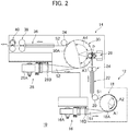
- Fig. 2 is a plan view.
- the filling and packaging machine 10 of the present embodiment is provided with an inner bag packaging machine 12 and an outer bag packaging machine 14.
- a long belt-shaped inner bag web (belt-shaped film) S1 is fed out from an inner bag material feeder 16 and supplied to a product-filling machine (product filling means) 18.
- the inner bag web S1 is fed out from a stock roll 16A installed on the inner bag material feeder 16, rendered horizontal at a guide roller 16B, and folded upward in half from a center crease along the longitudinal direction to be supplied to the product-filling machine 18 (inner-bag folding means).
- the product-filling machine 18 is provided with a rotating member 18A rotating about a vertical axis.
- the inner bag web S1 folded in half is run along the outer circumferential edge of the rotating member 18A in synchronization with the rotation of the rotating member 18A.
- the inner bag web S1 folded in half and wound around the rotating member 18A is vertically sealed (side seal) at set intervals in an upstream section (side-seal section) A1 along the longitudinal direction of the web whereby it is formed into bag shapes with open tops (inner-bag side seal means).
- hoppers 18B are arranged corresponding to the inner bags B1 formed by the side seals of the inner-bag web S1.
- the hoppers 18B are lowered and inserted inside the corresponding inner bags B1 at a downstream section (filling section) A2 following the upstream section A1 of the rotating member 18A whereupon the inner bags B1 are filled with contents deposited from above.
- the hoppers 18B are raised and the inner bag web S1, which is divided in the longitudinal direction by the side seals into a large number of inner bags B1 filled with content, separates from the rotating member 18A and is fed out through the guide roller 20 toward the outer bag packaging machine 14.
- the inner bag web S1 passing the guide roller 20 is fed out straight toward the outer bag packaging machine 14 and passed through a preheater 22 and top seal device (inner-bag top seal means) 24 where the opened top side of the folded inner bag web S1, that is, the part formed with the openings of the inner bags B1, is preheated along the longitudinal direction and the openings are completely sealed by the top seal device 24. Due to this, the contents filled in the inner bags B1 formed from the inner bag web S1 are sealed inside the inner bags B1.
- a cutter (inner-bag cutting means) 26 is arranged at a position adjoining the outer-bag packaging machine 14.
- the inner bags B1 of the inner-bag web S1 in which the contents are filled and sealed are individually cut off at their downstream side seal end positions by the cutter 26 to be separated into individual inner bags B1.
- the inner bags B1 separated from the inner-bag web S1 are, as explained later, held by a mechanism provided at the outer-bag packaging machine 14 and individually inserted into outer bags B2.
- a long belt-shaped outer-bag web S2 is fed out from an outer-bag feeder 28 and supplied to an inner-bag inserting machine (inner-bag inserting means) 30.
- the outer-bag web S2 is fed out from a stock roll 28A installed at the outer-bag feeder 28, rendered horizontal at a guide roller 28B, and folded upward in half from a center crease along the longitudinal direction to be supplied to the inner-bag inserting machine 30 (outer-bag folding means).
- the inner-bag inserting machine 30 is provided with a rotating member 30A rotating about a vertical axis.
- the outer bag web S2, folded in half, is run along the outer circumferential edge of the rotating member 30A in synchronization with the rotation of the rotating member 30A.
- the outer-bag web S2 folded in half and wound around the rotating member 30A is vertically sealed (side seal) at set intervals in an upstream section (side-seal section) A3 along the longitudinal direction of the web whereby it is formed into bag shapes with open tops (outer-bag side seal means).
- the inner bag web S1 fed out straight from the guide roller 20 toward the outer-bag packaging machine 14 is arranged tangentially with respect to the outer circumference of the rotating member 30A of the inner-bag inserting machine 30. Furthermore, the cutter 26 is arranged so as to cut the inner-bag web S1 at a position substantially corresponding to the point of contact P with the rotating member 30A. Hoppers 30B, which are inserted into the outer bags B2 to guide the inner bags B1 into the outer bags B2, and inner-bag holding devices 32, which hold the cut inner bags B1 and insert them into the corresponding hoppers 30B (see Fig. 4 , Fig. 6 , and Figs. 7A and 7B ), are arranged above the outer circumference of the rotating member 30A corresponding to the outer bags B2 with the capability of being raised and lowered.
- the inner bags B1 cut by the cutter 26 and held by the inner-bag holding devices (holding-part conveying means) 32 of the inner-bag inserting machine 30 are, as explained later, inserted at the downstream section (inserting section) A4 through the hoppers 30B into the outer bags B2, which were formed at the upstream section (side seal section) A3.
- the hoppers 30B are raised and retracted from the outer bags B2, whereupon the direction of the outer-bag web S2 is changed by the guide roller 34 and, in the same way as the inner-bag web S1, sealed at its top openings by a preheater 36 and top seal device (outer-bag top seal means) 38 whereby the inner bags B1 are sealed inside the outer bags B2.
- the outer-bag web S2 is cut by the cutter 40 at the side seal positions, whereby the individual packaging of the inner bags B1 within the outer bags B2 is completed.
- the rotating member 18A of the product-filling machine 18 is provided with a disk-shaped base board 180 attached through a bearing 181 around a fixed shaft 182 to be able to rotate.
- the base board 180 is rotated by a drive mechanism (not shown) in synchronization with the speed of conveyance of the inner-bag web S1.
- a drive mechanism (not shown)
- Arranged at set intervals along the outer circumference around the base board 180 is a plurality of side seal parts 184 over the outer cirumferences of which the folded inner-bag web S1 is strung.
- Each side seal part 184 is provided with a fixed seal bar 184A standing upright from the base board 180 and a swinging seal bar 184B positioned outside of the fixed seal bar 184A and having a base end part rotatably supported at an outer circumferential edge of the base board 180.
- the swinging seal bar 184B can swing between a prone state in which its front end faces radially outward and a standing state where it stands upright and is pressed against the fixed seal bar 184A.
- the swinging motion of the swinging seal bar 184B about the base end part is controlled by the engagement of a cam follower 184D and cam groove 184C provided at the front end of a pivoting lever 184E for pivoting the swinging seal bar 184B.
- the inner-bag web S1 is designed to run in a state pressed against the fixed seal bar 184A. If the swinging seal bar 184B is stood upright and pressed against the fixed seal bar 184A across the inner-bag web S1, the folded inner-bag web S1 is gripped between the fixed seal bar 184A and swinging seal bar 184B to be melted and thereby sealed with a side seal.
- the left side shows a swinging seal bar 184B in the prone state
- the right side shows a swinging seal bar 184B in the standing state.
- hoppers 18B are arranged above the side seal parts 184 and in the interval between two adjacent side seal parts 184.
- Each hopper 18B is supported by a hopper-elevating mechanism 186.
- the hopper 18B is supported at the top end of an elevating shaft 186A extending in the vertical direction of the hopper-elevating mechanism 186.
- the elevating shaft 186A is supported to be raised and lowered with respect to the base board 180 and is raised and lowered by engagement between a cam follower 186B and cam 186C provided at the bottom end of the elevating shaft 186A.
- the left side shows the state where a hopper 18B is raised and the right side shows the state where the hopper 18B is lowered with its front end inserted inside an inner bag B1 formed by a side seal of the inner-bag web S1.
- a tank 188 Arranged above the rotating member 18A is a tank 188 in which the content to be filled inside the inside bags B1 is stored. Above each hopper 18B, a filling nozzle 188A is provided for guiding the content from inside the tank 188 to the hopper 18B. At the filling section A2, the content inside the tank 188 falls through the filling nozzles 188A and hoppers 18B into the inner bags B1.
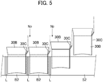
- FIG. 4 shows the operation of the section from the side seal section (upstream section) A3 of the inner-bag inserting machine 30 to the first half of the inserting section (downstream section) A4, while Fig. 5 is an enlarged view of the section A4 of Fig. 4 .
- hoppers 30B are successively inserted from above into the outer-bag web S2 folded in half.
- hoppers 30B are inserted from above into the outer-bag web S2 along the rear edge side seals L of the immediately preceding inserted hoppers 30B.
- the rear edge sides of the newly inserted hoppers 30B are sealed and the next hoppers 30B are similarly inserted into the outer-bag web S2 along the side seals L.
- the sealed inner-bag web S1 divided into inner bags B1 is conveyed from the tangential direction of the outer circumference of the inner-bag inserting machine 30.
- the inner-bag web S1 is gripped by grippers (holding parts) 32A of the inner-bag holding devices 32 successively at the tops of the inner bags B1 in front of the point of contact P where the outer circumference of the inner-bag inserting machine 30 and the straight trajectory of the inner-bag web S1 make contact with each other.
- the cutter 26 cuts the inner bag B1 from the inner-bag web S1 at the front end.
- the grippers 32A individually grip the inner bags B1 moving along the tangential direction in front of the point of contact P using linking mechanisms (described later) that protrude the grippers 32A radially outward from the outer circumference of the inner-bag inserting machine 30 and rotate so as to become parallel to the tangential direction.
- the grippers 32A are given pitches matching the pitch D1 of the inner bags B1 formed from the inner-bag web S1, but after cutting, are given pitches D2 of the outer bags B2 formed from the outer-bag web S2, that is, the pitch of the hoppers 30B.
- the grippers 32A are pulled radially inward and rotated to orientations following the outer circumference of the inner-bag inserting machine 30 to be returned to their original positions and orientations. That is, the grippers 32A move along the outer circumference of the inner-bag inserting machine 30 together with the hoppers 30B, that is, the outer bags B2.
- the grippers 32A starting to move along the outer circumference of the inner-bag inserting machine 30 are lowered to release at least part of the held inner bags B1 into the hoppers 30B positioned directly below them. Due to this, the inner bags B1 drop down through the interiors of the hoppers 30B and are deposited into the outer bags B2 into which the hoppers 30B are inserted.
- each hopper 30B is provided with a tube 30C for injecting nitrogen gas or other inert gas inside the outer bag B2.
- the nitrogen gas is injected inside the outer bag B2 while the hopper 30B is inserted inside the outer bag B2.
- the hopper 30B is raised and retracted from the outer bag B2 before the outer packaging film S2 reaches the guide roller 34.
- the hopper 30B and gripper 32A are moved along the outer circumference of the inner-bag inserting machine 30. When reaching the above-mentioned point of contact P, a similar operation is repeated.
- Fig. 6 is a partial side cross-sectional view of the inner-bag inserting machine 30 of the present embodiment.
- the inner-bag inserting machine 30 is provided with a fixed part 300 including a rotational shaft 300A and a rotating part 302 rotating about the rotational shaft 300A through a bearing 301.
- the rotating part 302 is provided with a base board 308, on which a side-seal part 304 and hopper-elevating mechanism 306 holding the hoppers 30B are arranged along the outer circumference, and a holding device support part 310 supporting the inner-bag holding devices 32.
- the rotating part 302 is rotated by a drive mechanism (not shown) in synchronization with a the speed of conveyance of the outer bag web S2.
- a drive mechanism (not shown)
- a plurality of side-seal parts 304 are arranged at set intervals along the outer circumference around the base board 308 .
- Each side-seal part 304 is provided with a fixed seal bar 304A standing upright from the base board 308 and a swinging seal bar 304B positioned outside of the fixed seal bar 304A and having a base end part rotatably supported at the outer circumferential edge of the base board 308.
- Each swinging seal bar 304B can swing between a prone state, where its front end faces radially outward, and a standing state, where it stands upright and is pressed against the fixed seal bar 304A.
- the swinging motion of the swinging seal bar 304B about the base end part is controlled by the engagement of a cam follower 304D and cam groove 304C provided at the front end of a pivoting lever 304E for pivoting the swinging seal bar 304B.
- the outer bag web S2 is run in a state pressed against the fixed seal bar 304A. If the swinging seal bar 304B is standing upright and pressed against the fixed seal bar 304A across the outer bag web S2, the folded outer bag web S2 is gripped between the fixed seal bar 304A and the swinging seal bar 304B and melted, thereby creating a side seal.
- Fig. 6 shows the swinging seal bar 304B in the prone state.
- hoppers 30B are respectively arranged.
- Each hopper 30B is supported by a hopper-elevating mechanism 306.
- the hopper 30B is supported at a top end of an elevating shaft 306A extending in the vertical direction of the hopper-elevating mechanism 306.
- the elevating shaft 306A is supported to be able to be raised and lowered with respect to the base board 308 and is raised and lowered by the engagement of a cam follower 306B and cam 306C provided at the bottom end of the elevating shaft 306A.
- Fig. 6 shows the state where a hopper 30B is lowered with its front end inserted into an outer bag B2 formed from the outer bag web S2.
- an inner-bag holding device 32 is arranged and supported by a holding device support part 310.
- the inner-bag holding device 32 is provided with a gripper operating mechanism 320 opening and closing a gripper 32A.
- the gripper operating mechanism 320 is attached to the bottom end of a vertically extending slide shaft 322.
- the slide shaft 322 can be raised and lowered with respect to the block 324.
- the block 324 houses a linking mechanism (pitch-widening mechanism; explained later) 42 inside it and is supported by a link box 326 held at the holding device support part 310.
- the linking mechanism 42 which is driven by the engagement of the three cam followers 42A, 42B, and 42C connected to the linking mechanism 42 and the cam grooves 42D, 42E, and 42F provided at the fixed part 300 along its entire circumference, controls the position and orientation of the block 324, that is, the slide shaft 322.
- the slide shaft 322 for example, is provided with a cam follower 322A near its top end.
- the cam follower 322A is engaged with a gripper-elevating cam 300B provided along the outer circumference of the fixed part 300. That is, the slide shaft 322 is raised and lowered with respect to the block 324 (holding part elevating means) by rotation of the rotary part 302 and movement of the cam follower 322A along the shape of the gripper-elevating cam 300B.
- the slide shaft 322 has a hollow structure into which an elevating shaft 328 for operating the gripper 32A is inserted.
- a top end of the elevating shaft 328 is provided with a cam follower 328A that is engaged with a gripper-operating cam 300c provided along an outer circumference of the fixed part 300. That is, the elevating shaft 328 is raised and lowered inside the slide shaft 322 by rotation of the rotary part 302 and movement of the cam follower 328A along the shape of the gripper-operating cam 300c.
- the bottom end of the elevating shaft 328 as explained later, is connected to the gripper-operating mechanism 320.
- the operation of the gripper 32A is performed by the vertical (up and down) motion of the elevating shaft 328.
- FIGs. 7A and 7B show the configuration of the inside of the gripper-operating mechanism 320.
- Fig. 7A is a side view of the internal structure of the gripper-operating mechanism 320 as seen from inside the inner bag inserting machine 30 in the radial direction
- Fig. 7B is a side view of the internal structure of the gripper-operating mechanism 320 from the direction shown in Fig. 6 .
- the gripper-operating mechanism 320 is covered by a cover 320A.
- the cover 320A is fixed to the bottom end part of the slide shaft 322.
- a bushing 322B is interposed between the outer circumferential surface of the elevating shaft 328 and the inner circumferential surface of the slide shaft 322.
- a base member 328B is fixed.
- the base member 328B is provided with a guide rod 328C parallel to the elevating shaft 328.
- the guide rod 328C which is inserted through a bushing 328E inside a bore 328D provided integrally at the cover 320A, guides the elevating action of the base member 328B by the elevating shaft 328.
- a downward-protruding operating cam 328F is provided at the bottom side of the base member 328B.
- the operating cam 328F engages with a pair of gripper pieces 320B and 320C forming a gripper 32A.
- the gripper pieces 320B and 320C are supported through bushings 320E around a rotational shaft 320D fixed to the cover 320A horizontally. The two are biased in a direction closing them by biasing members (not shown).
- the end parts at the base-part sides of the gripper pieces 320B and 320C (top end parts) are provided with cam followers 320F and 320G, respectively.
- the operating cam 328F is inserted between the cam followers 320F, 320G. If the base member 328B is lowered by the elevating shaft 328, the cam followers 320F and 320G are pushed apart against the biasing forces of the biasing members and the gripper pieces 320B and 320C are opened. If the elevating shaft 328 is raised from this state, the base member 328B is raised, the cam followers 320F and 320G approach each other due to the biasing forces, and the gripper pieces 320B and 320C are closed.
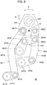
- FIG. 8 is a plan view of one linking mechanism 42, while
- Fig. 9 is a view showing the movement of the linking mechanism 42 near the point of contact P.
- the slide shaft 322 is configured to slide against the block 324 in the up-down direction and rotate together with it in the rotational direction.
- the block 324 is provided with a first link 421, second link 422, and third link 423.
- the links 421, 422, and 423 are respectively comprised of pairs of first and second levers (421A, 421B), (422A, 422B), and (423A, 423B).
- the first ends of the first levers 421A, 422A, and 423A of the links 421, 422, and 423 are respectively supported by the fixed shafts 421C, 422C, and 423C at the housing of the linking mechanism 42, for rotation.
- One end of the second lever 421B of the first link 421 and one end of the second lever 422B of the second link 422 are attached through the shafts 421D and 422D to the block 324, for rotation.
- one end of the second lever 423B of the third link 423 is supported through the shaft 423D at the second lever 422B of the second link 422.
- the other ends of the first levers 421A, 422A, and 423A and the other ends of the second levers 421B, 422B, and 423B are connected to be rotated by the shafts 421E, 422E, and 423E for movement in the respective horizontal planes.
- the point Q shows the reference point corresponding to the center position of the gripper 32A.
- the fixed shafts 421C, 422C, and 423C are respectively integrally provided with operating levers 425, 426, and 427 (see Fig. 6 and Fig. 9 ).
- the front ends of the operating levers 425, 426, and 427 are respectively provided with cam followers 42A, 42B, and 42C (see Fig. 6 and Fig. 9 ). If, along with the rotation of the rotary member 302, the cam followers 42A, 42B, and 42C respectively move along the cam grooves 42D, 42E, and 42F, the fixed shafts 421C, 422C, and 423C are rotated and the first link 421, second link 422, and third link 423 are respectively driven.
- the block 324 Due to the rotation of the fixed shafts 421C and 422C, the block 324, that is, the reference point Q, is retracted in the radial direction of the rotating member 302 (arrow A). Due to the rotation of the fixed shaft 423C, the angle of the block 324, that is, the angle of the gripper 32A with respect to the radial direction (or the tangential direction) is adjusted (arrow B).
- FIG. 9 shows the arrangement of the four linking mechanisms 42 near the point of contact P (alternately drawn by the solid lines and two-dot chain lines).
- the arrow C shows the running position and running direction of the inner-bag web S1
- the arrow D shows the rotational direction of the rotating member 302.
- the linking mechanism 42 at the position (a) pushes the block 324 outward in the radial direction and rotates its orientation counterclockwise so that the corresponding gripper 32A can grip the inner-bag web S1 conveyed straight in the arrow C direction.
- the linking mechanism 42 returns the gripper 32A to the reference position and orientation. That is, the pitch of the reference point Q is widened to D2 and the gripper 32A is maintained at the outer circumference position of the rotating member 302. Further, the orientation of the gripper 32A is maintained so that the gripped inner bag B1 follows along the circumferential direction (tangential direction) of the rotating member 302. The position and orientation of the gripper 32A are maintained by the linking mechanism 42 until the gripper 32A again reaches the position (a).
- the gripper 32A gripping the inner bag B1 is lowered while tracking the hopper 30B inserted into the outer bag B2.
- the gripper 32A releases the inner bag B1 the inner bag B1 passes through the hopper 30B positioned below it and is deposited into the outside bag B2.
- the gripper 32A is raised together with the hopper 30B to its original height and is moved toward the position (a) along with the rotation of the rotating member 302.
- a section can be provided where the inner bags and the inner-bag holding devices (grippers) of the inner-bag inserting machine run in parallel so that inner bags can be transferred from the product-filling machine to the inner-bag inserting machine continuously at a high speed. Due to this, the inner bags can be inserted at a high speed into the outer bags.
- the product-filling machine and the inner-bag inserting machine are both circular-shaped rotating circulating types of machines, but they are not limited to circular shapes so long as they are circulating types of machines provided with sections where the inner bags and the inner-bag holding parts of the inner-bag inserting machine run in parallel.
- grippers are used for the inner-bag holding devices, but the holding parts may also be suction types.
- the inner-bag web is made from a material capable of being extracting the content component
- the outer-bag web is made from an airtight material for sealing the inner bags.
- the contents and the materials of the inner-bag web and the outer-bag web are not limited to these options.
- the present invention can be applied to any contents and materials for double packaging using inner bags and outer bags formed by three-way seals.
Landscapes
- Engineering & Computer Science (AREA)
- Mechanical Engineering (AREA)
- Containers And Plastic Fillers For Packaging (AREA)
- Supplying Of Containers To The Packaging Station (AREA)
Description
- The present invention relates to a filling and packaging machine placing an inner bag formed by a three-way seal inside of an outer bag formed by a three-way seal.
- For teabags or other such products, it is known to individually package a mesh-shaped inner bag containing tea leaves, etc., inside of an air-tight outer bag (Japanese Patent No.
5230659 5230659 - However, with the configuration of Japanese Patent No.
5230659 -
WO 2011/048653 A1 teaches a filling and packaging machine comprising an inner-bag web conveying means for conveying an inner-bag web, an inner-bag folding means for folding the inner-bag web in half, an inner-bag side-sealing means for sealing the folded inner bag web at predetermined intervals in the conveyance direction at the sides of the inner bags, a product-filling means for filling the folded inner-bag web with a product deposited from above, an inner-bag top-sealing means for sealing the top of the inner bag web in which the product is filled, an inner-bag cutting means for cutting the side-sealed locations of the inner-bag web, an outer-bag web conveying means for conveying an outer-bag web, and an inner-bag inserting means for inserting cut-off inner bags from the top, the inner-bag inserting means comprising a holding part for holding inner bags, a holding-part conveying means for conveying the holding part, and a holding-part elevating means for raising and lowering the holding part. - The present invention is confronted with the technical problem of increasing the rate at which a filling and packaging machine inserts an inner bag formed by a three-way seal into an outer bag formed by a three-way seal.
- This problem is solved by means of a filling and packaging machine with the features of claim 1. Prefered embodiments are set out in the dependent claims.
-
-
Fig. 1 is a perspective view of a filling and packaging machine according to one embodiment of the present invention; -
Fig. 2 is a partial side cross-sectional view of the filling and packaging machine ofFig. 1 ; -
Fig. 3 is a partial side cross-sectional view of a product filling machine; -
Fig. 4 is a view showing the operation of the side seal section to the first half of the inserting section of the inside bag inserting machine laid out to the outside in the diametrical direction: -
Fig. 5 is an enlarged view of a section A3 (seeFig. 2 ) ofFig. 4 ; -
Fig. 6 is a partial side cross-sectional view of an inside bag inserting machine; -
Figs. 7A and7B show the configuration of an inside of a gripper operating mechanism; -
Fig. 8 is a plan view of a link mechanism; and -
Fig. 9 is a view showing the movement around the point of contact P of the link mechanism. - Below, an embodiment of the present invention will be explained with reference to the drawings.
Fig. 1 is a perspective view of a filling and packaging machine according to an embodiment of the present invention, whileFig. 2 is a plan view. - The filling and
packaging machine 10 of the present embodiment is provided with an innerbag packaging machine 12 and an outerbag packaging machine 14. At the innerbag packaging machine 12, a long belt-shaped inner bag web (belt-shaped film) S1 is fed out from an innerbag material feeder 16 and supplied to a product-filling machine (product filling means) 18. The inner bag web S1 is fed out from astock roll 16A installed on the innerbag material feeder 16, rendered horizontal at aguide roller 16B, and folded upward in half from a center crease along the longitudinal direction to be supplied to the product-filling machine 18 (inner-bag folding means). - The product-
filling machine 18 is provided with a rotatingmember 18A rotating about a vertical axis. The inner bag web S1 folded in half is run along the outer circumferential edge of the rotatingmember 18A in synchronization with the rotation of the rotatingmember 18A. The inner bag web S1 folded in half and wound around the rotatingmember 18A is vertically sealed (side seal) at set intervals in an upstream section (side-seal section) A1 along the longitudinal direction of the web whereby it is formed into bag shapes with open tops (inner-bag side seal means). - Above the outer circumference of the rotating
member 18A,hoppers 18B are arranged corresponding to the inner bags B1 formed by the side seals of the inner-bag web S1. Thehoppers 18B are lowered and inserted inside the corresponding inner bags B1 at a downstream section (filling section) A2 following the upstream section A1 of the rotatingmember 18A whereupon the inner bags B1 are filled with contents deposited from above. When filling is completed, thehoppers 18B are raised and the inner bag web S1, which is divided in the longitudinal direction by the side seals into a large number of inner bags B1 filled with content, separates from the rotatingmember 18A and is fed out through theguide roller 20 toward the outerbag packaging machine 14. - The inner bag web S1 passing the
guide roller 20 is fed out straight toward the outerbag packaging machine 14 and passed through apreheater 22 and top seal device (inner-bag top seal means) 24 where the opened top side of the folded inner bag web S1, that is, the part formed with the openings of the inner bags B1, is preheated along the longitudinal direction and the openings are completely sealed by thetop seal device 24. Due to this, the contents filled in the inner bags B1 formed from the inner bag web S1 are sealed inside the inner bags B1. - At the downstream end of the inner-bag web S1, a cutter (inner-bag cutting means) 26 is arranged at a position adjoining the outer-
bag packaging machine 14. The inner bags B1 of the inner-bag web S1 in which the contents are filled and sealed are individually cut off at their downstream side seal end positions by thecutter 26 to be separated into individual inner bags B1. The inner bags B1 separated from the inner-bag web S1 are, as explained later, held by a mechanism provided at the outer-bag packaging machine 14 and individually inserted into outer bags B2. - At the outer-
bag packaging machine 14, a long belt-shaped outer-bag web S2 is fed out from an outer-bag feeder 28 and supplied to an inner-bag inserting machine (inner-bag inserting means) 30. The outer-bag web S2 is fed out from astock roll 28A installed at the outer-bag feeder 28, rendered horizontal at aguide roller 28B, and folded upward in half from a center crease along the longitudinal direction to be supplied to the inner-bag inserting machine 30 (outer-bag folding means). - The inner-
bag inserting machine 30 is provided with a rotatingmember 30A rotating about a vertical axis. The outer bag web S2, folded in half, is run along the outer circumferential edge of the rotatingmember 30A in synchronization with the rotation of the rotatingmember 30A. The outer-bag web S2 folded in half and wound around the rotatingmember 30A is vertically sealed (side seal) at set intervals in an upstream section (side-seal section) A3 along the longitudinal direction of the web whereby it is formed into bag shapes with open tops (outer-bag side seal means). - The inner bag web S1 fed out straight from the
guide roller 20 toward the outer-bag packaging machine 14 is arranged tangentially with respect to the outer circumference of the rotatingmember 30A of the inner-bag inserting machine 30. Furthermore, thecutter 26 is arranged so as to cut the inner-bag web S1 at a position substantially corresponding to the point of contact P with the rotatingmember 30A.Hoppers 30B, which are inserted into the outer bags B2 to guide the inner bags B1 into the outer bags B2, and inner-bag holding devices 32, which hold the cut inner bags B1 and insert them into thecorresponding hoppers 30B (seeFig. 4 ,Fig. 6 , andFigs. 7A and7B ), are arranged above the outer circumference of the rotatingmember 30A corresponding to the outer bags B2 with the capability of being raised and lowered. - The inner bags B1 cut by the
cutter 26 and held by the inner-bag holding devices (holding-part conveying means) 32 of the inner-bag inserting machine 30 are, as explained later, inserted at the downstream section (inserting section) A4 through thehoppers 30B into the outer bags B2, which were formed at the upstream section (side seal section) A3. After the inner bags B1 are inserted, thehoppers 30B are raised and retracted from the outer bags B2, whereupon the direction of the outer-bag web S2 is changed by theguide roller 34 and, in the same way as the inner-bag web S1, sealed at its top openings by apreheater 36 and top seal device (outer-bag top seal means) 38 whereby the inner bags B1 are sealed inside the outer bags B2. After being sealed, the outer-bag web S2 is cut by thecutter 40 at the side seal positions, whereby the individual packaging of the inner bags B1 within the outer bags B2 is completed. - Next, referring to the side cross-sectional view of the product-
filling machine 18 ofFig. 3 , the configuration of the product-filling machine 18 will be explained in more detail. - The rotating
member 18A of the product-filling machine 18 is provided with a disk-shaped base board 180 attached through abearing 181 around a fixedshaft 182 to be able to rotate. Thebase board 180 is rotated by a drive mechanism (not shown) in synchronization with the speed of conveyance of the inner-bag web S1. Arranged at set intervals along the outer circumference around thebase board 180 is a plurality ofside seal parts 184 over the outer cirumferences of which the folded inner-bag web S1 is strung. - Each
side seal part 184 is provided with afixed seal bar 184A standing upright from thebase board 180 and a swingingseal bar 184B positioned outside of thefixed seal bar 184A and having a base end part rotatably supported at an outer circumferential edge of thebase board 180. The swingingseal bar 184B can swing between a prone state in which its front end faces radially outward and a standing state where it stands upright and is pressed against the fixedseal bar 184A. The swinging motion of the swingingseal bar 184B about the base end part is controlled by the engagement of acam follower 184D andcam groove 184C provided at the front end of apivoting lever 184E for pivoting the swingingseal bar 184B. - The inner-bag web S1 is designed to run in a state pressed against the
fixed seal bar 184A. If the swingingseal bar 184B is stood upright and pressed against thefixed seal bar 184A across the inner-bag web S1, the folded inner-bag web S1 is gripped between thefixed seal bar 184A and swingingseal bar 184B to be melted and thereby sealed with a side seal. InFig. 3 , the left side shows a swingingseal bar 184B in the prone state, while the right side shows a swingingseal bar 184B in the standing state. - Above the
side seal parts 184 and in the interval between two adjacentside seal parts 184,hoppers 18B are arranged. Eachhopper 18B is supported by a hopper-elevatingmechanism 186. Thehopper 18B is supported at the top end of an elevatingshaft 186A extending in the vertical direction of the hopper-elevatingmechanism 186. The elevatingshaft 186A is supported to be raised and lowered with respect to thebase board 180 and is raised and lowered by engagement between acam follower 186B andcam 186C provided at the bottom end of the elevatingshaft 186A. InFig. 3 , the left side shows the state where ahopper 18B is raised and the right side shows the state where thehopper 18B is lowered with its front end inserted inside an inner bag B1 formed by a side seal of the inner-bag web S1. - Arranged above the rotating
member 18A is atank 188 in which the content to be filled inside the inside bags B1 is stored. Above eachhopper 18B, a fillingnozzle 188A is provided for guiding the content from inside thetank 188 to thehopper 18B. At the filling section A2, the content inside thetank 188 falls through the fillingnozzles 188A andhoppers 18B into the inner bags B1. - Next, referring to
Figs. 4 and5 , the operation for inserting an inner bag B1 into an outer bag B2 at the inner-bag inserting machine 30 will be explained.Fig. 4 shows the operation of the section from the side seal section (upstream section) A3 of the inner-bag inserting machine 30 to the first half of the inserting section (downstream section) A4, whileFig. 5 is an enlarged view of the section A4 ofFig. 4 . - As shown in
Fig. 4 ,hoppers 30B are successively inserted from above into the outer-bag web S2 folded in half. At the side-seal section (upstream section) A3,hoppers 30B are inserted from above into the outer-bag web S2 along the rear edge side seals L of the immediately preceding insertedhoppers 30B. Afterward, the rear edge sides of the newly insertedhoppers 30B are sealed and thenext hoppers 30B are similarly inserted into the outer-bag web S2 along the side seals L. - Above the outer-bag web S2 into which the
hoppers 30B are inserted and divided into individual outer bags B2 by side seals, the sealed inner-bag web S1 divided into inner bags B1 is conveyed from the tangential direction of the outer circumference of the inner-bag inserting machine 30. The inner-bag web S1 is gripped by grippers (holding parts) 32A of the inner-bag holding devices 32 successively at the tops of the inner bags B1 in front of the point of contact P where the outer circumference of the inner-bag inserting machine 30 and the straight trajectory of the inner-bag web S1 make contact with each other. Near the point of contact P, thecutter 26 cuts the inner bag B1 from the inner-bag web S1 at the front end. At this time, thegrippers 32A individually grip the inner bags B1 moving along the tangential direction in front of the point of contact P using linking mechanisms (described later) that protrude thegrippers 32A radially outward from the outer circumference of the inner-bag inserting machine 30 and rotate so as to become parallel to the tangential direction. - Furthermore, while holding the inner bags B1 until the inner bags B1 are cut, the
grippers 32A are given pitches matching the pitch D1 of the inner bags B1 formed from the inner-bag web S1, but after cutting, are given pitches D2 of the outer bags B2 formed from the outer-bag web S2, that is, the pitch of thehoppers 30B. Afterward, thegrippers 32A are pulled radially inward and rotated to orientations following the outer circumference of the inner-bag inserting machine 30 to be returned to their original positions and orientations. That is, thegrippers 32A move along the outer circumference of the inner-bag inserting machine 30 together with thehoppers 30B, that is, the outer bags B2. - The
grippers 32A starting to move along the outer circumference of the inner-bag inserting machine 30 are lowered to release at least part of the held inner bags B1 into thehoppers 30B positioned directly below them. Due to this, the inner bags B1 drop down through the interiors of thehoppers 30B and are deposited into the outer bags B2 into which thehoppers 30B are inserted. - Furthermore, each
hopper 30B is provided with atube 30C for injecting nitrogen gas or other inert gas inside the outer bag B2. The nitrogen gas is injected inside the outer bag B2 while thehopper 30B is inserted inside the outer bag B2. Thehopper 30B is raised and retracted from the outer bag B2 before the outer packaging film S2 reaches theguide roller 34. Afterward, thehopper 30B and gripper 32A are moved along the outer circumference of the inner-bag inserting machine 30. When reaching the above-mentioned point of contact P, a similar operation is repeated. -
Fig. 6 is a partial side cross-sectional view of the inner-bag inserting machine 30 of the present embodiment. The inner-bag inserting machine 30 is provided with afixed part 300 including arotational shaft 300A and arotating part 302 rotating about therotational shaft 300A through abearing 301. Therotating part 302 is provided with abase board 308, on which a side-seal part 304 and hopper-elevatingmechanism 306 holding thehoppers 30B are arranged along the outer circumference, and a holdingdevice support part 310 supporting the inner-bag holding devices 32. - The
rotating part 302 is rotated by a drive mechanism (not shown) in synchronization with a the speed of conveyance of the outer bag web S2. Arranged at set intervals along the outer circumference around thebase board 308 is a plurality of side-seal parts 304 over the outer circumferences of which the folded outer bag web S2 is strung. Each side-seal part 304 is provided with a fixedseal bar 304A standing upright from thebase board 308 and a swinging seal bar 304B positioned outside of the fixedseal bar 304A and having a base end part rotatably supported at the outer circumferential edge of thebase board 308. - Each swinging seal bar 304B can swing between a prone state, where its front end faces radially outward, and a standing state, where it stands upright and is pressed against the fixed
seal bar 304A. The swinging motion of the swinging seal bar 304B about the base end part is controlled by the engagement of a cam follower 304D andcam groove 304C provided at the front end of a pivotinglever 304E for pivoting the swinging seal bar 304B. - The outer bag web S2 is run in a state pressed against the fixed
seal bar 304A. If the swinging seal bar 304B is standing upright and pressed against the fixedseal bar 304A across the outer bag web S2, the folded outer bag web S2 is gripped between the fixedseal bar 304A and the swinging seal bar 304B and melted, thereby creating a side seal.Fig. 6 shows the swinging seal bar 304B in the prone state. - Above the
side seal parts 304 and in the interval between every two adjacentside seal parts 304,hoppers 30B are respectively arranged. Eachhopper 30B is supported by a hopper-elevatingmechanism 306. Thehopper 30B is supported at a top end of an elevatingshaft 306A extending in the vertical direction of the hopper-elevatingmechanism 306. The elevatingshaft 306A is supported to be able to be raised and lowered with respect to thebase board 308 and is raised and lowered by the engagement of acam follower 306B andcam 306C provided at the bottom end of the elevatingshaft 306A.Fig. 6 shows the state where ahopper 30B is lowered with its front end inserted into an outer bag B2 formed from the outer bag web S2. - Above each
hopper 30B, an inner-bag holding device 32 is arranged and supported by a holdingdevice support part 310. The inner-bag holding device 32 is provided with agripper operating mechanism 320 opening and closing agripper 32A. Thegripper operating mechanism 320 is attached to the bottom end of a vertically extendingslide shaft 322. Theslide shaft 322 can be raised and lowered with respect to theblock 324. Theblock 324 houses a linking mechanism (pitch-widening mechanism; explained later) 42 inside it and is supported by alink box 326 held at the holdingdevice support part 310. Note that, the linkingmechanism 42, which is driven by the engagement of the threecam followers linking mechanism 42 and thecam grooves fixed part 300 along its entire circumference, controls the position and orientation of theblock 324, that is, theslide shaft 322. - The
slide shaft 322, for example, is provided with acam follower 322A near its top end. Thecam follower 322A is engaged with a gripper-elevatingcam 300B provided along the outer circumference of thefixed part 300. That is, theslide shaft 322 is raised and lowered with respect to the block 324 (holding part elevating means) by rotation of therotary part 302 and movement of thecam follower 322A along the shape of the gripper-elevatingcam 300B. - Furthermore, the
slide shaft 322 has a hollow structure into which an elevatingshaft 328 for operating thegripper 32A is inserted. A top end of the elevatingshaft 328 is provided with acam follower 328A that is engaged with a gripper-operating cam 300c provided along an outer circumference of thefixed part 300. That is, the elevatingshaft 328 is raised and lowered inside theslide shaft 322 by rotation of therotary part 302 and movement of thecam follower 328A along the shape of the gripper-operating cam 300c. The bottom end of the elevatingshaft 328, as explained later, is connected to the gripper-operating mechanism 320. The operation of thegripper 32A is performed by the vertical (up and down) motion of the elevatingshaft 328. - Referring to
Figs. 7A and7B , the operation of agripper 32A will be explained.Figs. 7A and7B show the configuration of the inside of the gripper-operating mechanism 320.Fig. 7A is a side view of the internal structure of the gripper-operating mechanism 320 as seen from inside the innerbag inserting machine 30 in the radial direction, whileFig. 7B is a side view of the internal structure of the gripper-operating mechanism 320 from the direction shown inFig. 6 . - The gripper-
operating mechanism 320 is covered by acover 320A. Thecover 320A is fixed to the bottom end part of theslide shaft 322. At the bottom end part of theslide shaft 322, abushing 322B is interposed between the outer circumferential surface of the elevatingshaft 328 and the inner circumferential surface of theslide shaft 322. At the bottom end of the elevatingshaft 328, abase member 328B is fixed. Thebase member 328B is provided with aguide rod 328C parallel to the elevatingshaft 328. Theguide rod 328C, which is inserted through abushing 328E inside abore 328D provided integrally at thecover 320A, guides the elevating action of thebase member 328B by the elevatingshaft 328. - At the bottom side of the
base member 328B, a downward-protrudingoperating cam 328F is provided. Theoperating cam 328F engages with a pair ofgripper pieces gripper 32A. Thegripper pieces bushings 320E around arotational shaft 320D fixed to thecover 320A horizontally. The two are biased in a direction closing them by biasing members (not shown). The end parts at the base-part sides of thegripper pieces cam followers - The
operating cam 328F is inserted between thecam followers base member 328B is lowered by the elevatingshaft 328, thecam followers gripper pieces shaft 328 is raised from this state, thebase member 328B is raised, thecam followers gripper pieces - Next, referring to
Fig. 8 andFig. 9 , the structure and operation of the linkingmechanism 42 in theblock 324 will be explained.Fig. 8 is a plan view of onelinking mechanism 42, while -
Fig. 9 is a view showing the movement of the linkingmechanism 42 near the point of contact P. - The
slide shaft 322 is configured to slide against theblock 324 in the up-down direction and rotate together with it in the rotational direction. Theblock 324 is provided with afirst link 421,second link 422, andthird link 423. Thelinks first levers links shafts mechanism 42, for rotation. - One end of the
second lever 421B of thefirst link 421 and one end of thesecond lever 422B of thesecond link 422 are attached through theshafts block 324, for rotation. On the other hand, one end of thesecond lever 423B of thethird link 423 is supported through theshaft 423D at thesecond lever 422B of thesecond link 422. Furthermore, the other ends of thefirst levers second levers shafts Fig. 8 , the point Q shows the reference point corresponding to the center position of thegripper 32A. - The fixed
shafts operating levers Fig. 6 andFig. 9 ). The front ends of the operating levers 425, 426, and 427 are respectively provided withcam followers Fig. 6 andFig. 9 ). If, along with the rotation of therotary member 302, thecam followers cam grooves shafts first link 421,second link 422, andthird link 423 are respectively driven. - Due to the rotation of the fixed
shafts block 324, that is, the reference point Q, is retracted in the radial direction of the rotating member 302 (arrow A). Due to the rotation of the fixedshaft 423C, the angle of theblock 324, that is, the angle of thegripper 32A with respect to the radial direction (or the tangential direction) is adjusted (arrow B). - The plan view of
Fig. 9 shows the arrangement of the four linkingmechanisms 42 near the point of contact P (alternately drawn by the solid lines and two-dot chain lines). InFig. 9 , the arrow C shows the running position and running direction of the inner-bag web S1, while the arrow D shows the rotational direction of the rotatingmember 302. As shown inFig. 9 , the linkingmechanism 42 at the position (a) pushes theblock 324 outward in the radial direction and rotates its orientation counterclockwise so that thecorresponding gripper 32A can grip the inner-bag web S1 conveyed straight in the arrow C direction. - The
grippers 32A connected to the linkingmechanisms 42 at the positions (b) and (c), respectively, grip the tops of the inner bags B1 of the inner-bag web S1 at the pitch D1 and move straight along the arrow C direction without changing orientation. That is, the linkingmechanisms 42 at the positions (b) and (c) are driven so that the positions and orientations of thegrippers 32A change in this way. - When the
cutter 26 cuts off an inner bag B1 from the inner-bag web S1, the linkingmechanism 42 returns thegripper 32A to the reference position and orientation. That is, the pitch of the reference point Q is widened to D2 and thegripper 32A is maintained at the outer circumference position of the rotatingmember 302. Further, the orientation of thegripper 32A is maintained so that the gripped inner bag B1 follows along the circumferential direction (tangential direction) of the rotatingmember 302. The position and orientation of thegripper 32A are maintained by the linkingmechanism 42 until thegripper 32A again reaches the position (a). - Downstream of the position (d), the
gripper 32A gripping the inner bag B1 is lowered while tracking thehopper 30B inserted into the outer bag B2. When thegripper 32A releases the inner bag B1, the inner bag B1 passes through thehopper 30B positioned below it and is deposited into the outside bag B2. Afterward, thegripper 32A is raised together with thehopper 30B to its original height and is moved toward the position (a) along with the rotation of the rotatingmember 302. - In this way, according to the present embodiment, a section can be provided where the inner bags and the inner-bag holding devices (grippers) of the inner-bag inserting machine run in parallel so that inner bags can be transferred from the product-filling machine to the inner-bag inserting machine continuously at a high speed. Due to this, the inner bags can be inserted at a high speed into the outer bags.
- Note that, in the present embodiment, the product-filling machine and the inner-bag inserting machine are both circular-shaped rotating circulating types of machines, but they are not limited to circular shapes so long as they are circulating types of machines provided with sections where the inner bags and the inner-bag holding parts of the inner-bag inserting machine run in parallel. Furthermore, in the present embodiment, grippers are used for the inner-bag holding devices, but the holding parts may also be suction types.
- Note that, as examples of the contents filled inside the inner bags, powdered soup stock, tea leaves, etc., may be mentioned. In this case, the inner-bag web is made from a material capable of being extracting the content component, while the outer-bag web is made from an airtight material for sealing the inner bags. However, the contents and the materials of the inner-bag web and the outer-bag web are not limited to these options. The present invention can be applied to any contents and materials for double packaging using inner bags and outer bags formed by three-way seals.
- Although the embodiments of the present invention have been described herein with reference to the accompanying drawings, obviously many modifications and changes may be made by those skilled in this art without departing from the scope of the invention as defined in the claims.
Claims (3)
- A filling and packaging machine comprising
an inner-bag web conveying means (16) for conveying an inner-bag web (S1);
an inner-bag folding means (18) for folding the inner-bag web in half;
an inner-bag side-sealing means for sealing the folded inner-bag web at predetermined intervals in the conveyance direction at the sides of the inner bags;
a product-filling means for filling the folded inner-bag web with a product deposited from above;
an inner-bag top-sealing means (24) for sealing the top of the inner-bag web in which the product is filled;
an inner-bag cutting means (26) for cutting the side-sealed locations of the inner-bag web;
an outer-bag web conveying means (28) for conveying an outer-bag web (S2);
an outer-bag folding means for folding the outer-bag web in half;
an outer-bag side-sealing means for sealing the folded outer-bag web at predetermined intervals in the conveyance direction at the sides of the outer bags;
an inner-bag inserting means (30) for inserting cut-off inner bags from the top of the folded outer-bag web; and
an outer-bag top-sealing means (38) for sealing the top of the outer-bag web in which the inner bags are inserted;
the inner-bag inserting means comprising a plurality of holding parts (32A) for holding inner bags, a holding-part conveying means (32) for conveying the holding parts to track the outer bags, and a holding-part elevating means for raising and lowering the holding parts;
the holding parts (32A) beifng configured to hold and convey the inner bags before the inner bags are cut by the inner-bag cutting means and configured to lower the inner bags while tracking the outer bags after the inner bags are cut off, thereby configured to insert the inner bags into the outer bags. - A filling and packaging machine according to claim 1, wherein
the holding-part conveying means (32) is provided with a pitch-widening mechanism for widening the pitch of the holding parts (32A) in such a manner that the holding parts are widened in pitch so that the inner bags after being cut have the same pitch as the outer bags. - A filling and packaging machine according to claim 1 or 2 wherein
the inner-bag inserting means (30) is provided with a rotating member (30A) in which the outer-bag side-sealing means and the inner-bag inserting means are arranged along its circumference; and
the inner-bag web conveying means (16) is configured to convey the inner-bag web before cutting toward a tangential direction of the rotating member and the inner-bag cutting means (26) is arranged at the point of contact between the inner-bag web and the rotating member.
Applications Claiming Priority (1)
| Application Number | Priority Date | Filing Date | Title |
|---|---|---|---|
| JP2018095106A JP7079653B2 (en) | 2018-05-17 | 2018-05-17 | Filling and packaging machine |
Publications (2)
| Publication Number | Publication Date |
|---|---|
| EP3569510A1 EP3569510A1 (en) | 2019-11-20 |
| EP3569510B1 true EP3569510B1 (en) | 2020-12-30 |
Family
ID=66589298
Family Applications (1)
| Application Number | Title | Priority Date | Filing Date |
|---|---|---|---|
| EP19174847.4A Active EP3569510B1 (en) | 2018-05-17 | 2019-05-16 | Filling and packaging machine |
Country Status (3)
| Country | Link |
|---|---|
| EP (1) | EP3569510B1 (en) |
| JP (1) | JP7079653B2 (en) |
| ES (1) | ES2855727T3 (en) |
Families Citing this family (1)
| Publication number | Priority date | Publication date | Assignee | Title |
|---|---|---|---|---|
| JP7656192B2 (en) | 2021-08-16 | 2025-04-03 | シブヤパッケージングシステム株式会社 | Filling and packaging machine |
Family Cites Families (8)
| Publication number | Priority date | Publication date | Assignee | Title |
|---|---|---|---|---|
| US2330361A (en) * | 1941-03-14 | 1943-09-28 | Pneumatic Scale Corp | Method of and apparatus for producing bags |
| JPS5230659B2 (en) | 1971-09-23 | 1977-08-09 | ||
| DE60305883T2 (en) * | 2002-02-22 | 2006-10-19 | Molins Plc, Blakelands | teabag |
| US6615882B1 (en) | 2002-03-11 | 2003-09-09 | Shui Yung Hsieh | Filling device of a dual layered filling and packing device |
| JP2004244085A (en) | 2003-02-17 | 2004-09-02 | Toyo Jidoki Co Ltd | Bag making and packaging machine |
| EP2453506B1 (en) * | 2009-07-08 | 2016-12-28 | Mitsubishi Rayon Co., Ltd. | Porous electrode base material, and process for production thereof |
| JP5286421B2 (en) * | 2009-10-19 | 2013-09-11 | 大紀商事株式会社 | Packaging equipment |
| CN104661921A (en) * | 2012-08-31 | 2015-05-27 | 株式会社发布利卡图雅玛 | Manufacturing method and manufacturing device for extract bag package |
-
2018
- 2018-05-17 JP JP2018095106A patent/JP7079653B2/en active Active
-
2019
- 2019-05-16 EP EP19174847.4A patent/EP3569510B1/en active Active
- 2019-05-16 ES ES19174847T patent/ES2855727T3/en active Active
Non-Patent Citations (1)
| Title |
|---|
| None * |
Also Published As
| Publication number | Publication date |
|---|---|
| JP2019199283A (en) | 2019-11-21 |
| ES2855727T3 (en) | 2021-09-24 |
| EP3569510A1 (en) | 2019-11-20 |
| JP7079653B2 (en) | 2022-06-02 |
Similar Documents
| Publication | Publication Date | Title |
|---|---|---|
| US4774797A (en) | Method of wrapping various products in packaging made from sheet material, a device for working the method, and packaging thus obtained | |
| US3902710A (en) | Accordion, folding and cutting apparatus | |
| US4845924A (en) | Process and apparatus for the packaging of paper handkerchiefs | |
| US4034537A (en) | Method and apparatus for the continuous manufacture of packages for liquids | |
| EP0061631B1 (en) | A device for packing sheet-like elements | |
| KR101984517B1 (en) | Bag transfer device | |
| US5685131A (en) | Heat sealing device | |
| US4484432A (en) | Bottom-folding packaging machine | |
| US5972153A (en) | Method for manufacturing labels and applying them to packets | |
| US4117649A (en) | System for forming, filling and closing bags | |
| US4909020A (en) | Process and apparatus for wrapping, especially cigarette packs | |
| JP2014522785A (en) | Packaging machine and method for producing a rigid packet each comprising at least two containers, one container inside another container | |
| GB2146608A (en) | Cigarette packing machines | |
| AU2003266959B2 (en) | Installation for producing and packing tubes | |
| US5030191A (en) | Device for depositing and stacking bags produced from synthetic resin films and having a bottom seam | |
| US3285145A (en) | Carton setting up machine | |
| EP3569510A1 (en) | Filling and packaging machine | |
| US20080138187A1 (en) | Method For Handling a Blister in a Blister Packaging Machine and Device For Carrying Out Said Method | |
| US6298980B1 (en) | Sheet material arranging and feeding conveyor | |
| CN1671542A (en) | A system for forming containers, in particular containers for food products | |
| US3672265A (en) | Apparatus for stacking flattened bags of thermoplastic material which are made in a bag-making machine | |
| US4258525A (en) | Method and apparatus for wrapping groups of cigarettes | |
| KR102042962B1 (en) | Continuous vacuum system | |
| WO1996001209A1 (en) | Producing shaped articles from a web | |
| US4913765A (en) | Apparatus for making bags or sacks from a preferably gusseted continuous tubular film of thermoplastic plastic |
Legal Events
| Date | Code | Title | Description |
|---|---|---|---|
| PUAI | Public reference made under article 153(3) epc to a published international application that has entered the european phase |
Free format text: ORIGINAL CODE: 0009012 |
|
| STAA | Information on the status of an ep patent application or granted ep patent |
Free format text: STATUS: THE APPLICATION HAS BEEN PUBLISHED |
|
| AK | Designated contracting states |
Kind code of ref document: A1 Designated state(s): AL AT BE BG CH CY CZ DE DK EE ES FI FR GB GR HR HU IE IS IT LI LT LU LV MC MK MT NL NO PL PT RO RS SE SI SK SM TR |
|
| AX | Request for extension of the european patent |
Extension state: BA ME |
|
| STAA | Information on the status of an ep patent application or granted ep patent |
Free format text: STATUS: REQUEST FOR EXAMINATION WAS MADE |
|
| 17P | Request for examination filed |
Effective date: 20200402 |
|
| RBV | Designated contracting states (corrected) |
Designated state(s): AL AT BE BG CH CY CZ DE DK EE ES FI FR GB GR HR HU IE IS IT LI LT LU LV MC MK MT NL NO PL PT RO RS SE SI SK SM TR |
|
| GRAP | Despatch of communication of intention to grant a patent |
Free format text: ORIGINAL CODE: EPIDOSNIGR1 |
|
| STAA | Information on the status of an ep patent application or granted ep patent |
Free format text: STATUS: GRANT OF PATENT IS INTENDED |
|
| RIC1 | Information provided on ipc code assigned before grant |
Ipc: B65B 9/087 20120101ALI20200724BHEP Ipc: B65B 29/02 20060101ALI20200724BHEP Ipc: B65B 35/16 20060101AFI20200724BHEP Ipc: B65B 39/12 20060101ALI20200724BHEP Ipc: B65B 43/60 20060101ALI20200724BHEP Ipc: B65B 39/14 20060101ALI20200724BHEP |
|
| INTG | Intention to grant announced |
Effective date: 20200818 |
|
| RIN1 | Information on inventor provided before grant (corrected) |
Inventor name: SUNADA, MASAHIRO Inventor name: SAWADA, KIYOSHI |
|
| GRAS | Grant fee paid |
Free format text: ORIGINAL CODE: EPIDOSNIGR3 |
|
| RAP1 | Party data changed (applicant data changed or rights of an application transferred) |
Owner name: SHIBUYA PACKAGING SYSTEM CORPORATION |
|
| GRAA | (expected) grant |
Free format text: ORIGINAL CODE: 0009210 |
|
| STAA | Information on the status of an ep patent application or granted ep patent |
Free format text: STATUS: THE PATENT HAS BEEN GRANTED |
|
| AK | Designated contracting states |
Kind code of ref document: B1 Designated state(s): AL AT BE BG CH CY CZ DE DK EE ES FI FR GB GR HR HU IE IS IT LI LT LU LV MC MK MT NL NO PL PT RO RS SE SI SK SM TR |
|
| REG | Reference to a national code |
Ref country code: GB Ref legal event code: FG4D |
|
| REG | Reference to a national code |
Ref country code: AT Ref legal event code: REF Ref document number: 1349714 Country of ref document: AT Kind code of ref document: T Effective date: 20210115 |
|
| REG | Reference to a national code |
Ref country code: DE Ref legal event code: R096 Ref document number: 602019001948 Country of ref document: DE |
|
| REG | Reference to a national code |
Ref country code: IE Ref legal event code: FG4D |
|
| PG25 | Lapsed in a contracting state [announced via postgrant information from national office to epo] |
Ref country code: NO Free format text: LAPSE BECAUSE OF FAILURE TO SUBMIT A TRANSLATION OF THE DESCRIPTION OR TO PAY THE FEE WITHIN THE PRESCRIBED TIME-LIMIT Effective date: 20210330 Ref country code: GR Free format text: LAPSE BECAUSE OF FAILURE TO SUBMIT A TRANSLATION OF THE DESCRIPTION OR TO PAY THE FEE WITHIN THE PRESCRIBED TIME-LIMIT Effective date: 20210331 Ref country code: FI Free format text: LAPSE BECAUSE OF FAILURE TO SUBMIT A TRANSLATION OF THE DESCRIPTION OR TO PAY THE FEE WITHIN THE PRESCRIBED TIME-LIMIT Effective date: 20201230 Ref country code: RS Free format text: LAPSE BECAUSE OF FAILURE TO SUBMIT A TRANSLATION OF THE DESCRIPTION OR TO PAY THE FEE WITHIN THE PRESCRIBED TIME-LIMIT Effective date: 20201230 |
|
| REG | Reference to a national code |
Ref country code: AT Ref legal event code: MK05 Ref document number: 1349714 Country of ref document: AT Kind code of ref document: T Effective date: 20201230 |
|
| PG25 | Lapsed in a contracting state [announced via postgrant information from national office to epo] |
Ref country code: LV Free format text: LAPSE BECAUSE OF FAILURE TO SUBMIT A TRANSLATION OF THE DESCRIPTION OR TO PAY THE FEE WITHIN THE PRESCRIBED TIME-LIMIT Effective date: 20201230 Ref country code: SE Free format text: LAPSE BECAUSE OF FAILURE TO SUBMIT A TRANSLATION OF THE DESCRIPTION OR TO PAY THE FEE WITHIN THE PRESCRIBED TIME-LIMIT Effective date: 20201230 Ref country code: BG Free format text: LAPSE BECAUSE OF FAILURE TO SUBMIT A TRANSLATION OF THE DESCRIPTION OR TO PAY THE FEE WITHIN THE PRESCRIBED TIME-LIMIT Effective date: 20210330 |
|
| REG | Reference to a national code |
Ref country code: NL Ref legal event code: MP Effective date: 20201230 |
|
| PG25 | Lapsed in a contracting state [announced via postgrant information from national office to epo] |
Ref country code: HR Free format text: LAPSE BECAUSE OF FAILURE TO SUBMIT A TRANSLATION OF THE DESCRIPTION OR TO PAY THE FEE WITHIN THE PRESCRIBED TIME-LIMIT Effective date: 20201230 |
|
| REG | Reference to a national code |
Ref country code: LT Ref legal event code: MG9D |
|
| PG25 | Lapsed in a contracting state [announced via postgrant information from national office to epo] |
Ref country code: LT Free format text: LAPSE BECAUSE OF FAILURE TO SUBMIT A TRANSLATION OF THE DESCRIPTION OR TO PAY THE FEE WITHIN THE PRESCRIBED TIME-LIMIT Effective date: 20201230 Ref country code: PT Free format text: LAPSE BECAUSE OF FAILURE TO SUBMIT A TRANSLATION OF THE DESCRIPTION OR TO PAY THE FEE WITHIN THE PRESCRIBED TIME-LIMIT Effective date: 20210430 Ref country code: RO Free format text: LAPSE BECAUSE OF FAILURE TO SUBMIT A TRANSLATION OF THE DESCRIPTION OR TO PAY THE FEE WITHIN THE PRESCRIBED TIME-LIMIT Effective date: 20201230 Ref country code: CZ Free format text: LAPSE BECAUSE OF FAILURE TO SUBMIT A TRANSLATION OF THE DESCRIPTION OR TO PAY THE FEE WITHIN THE PRESCRIBED TIME-LIMIT Effective date: 20201230 Ref country code: EE Free format text: LAPSE BECAUSE OF FAILURE TO SUBMIT A TRANSLATION OF THE DESCRIPTION OR TO PAY THE FEE WITHIN THE PRESCRIBED TIME-LIMIT Effective date: 20201230 Ref country code: SK Free format text: LAPSE BECAUSE OF FAILURE TO SUBMIT A TRANSLATION OF THE DESCRIPTION OR TO PAY THE FEE WITHIN THE PRESCRIBED TIME-LIMIT Effective date: 20201230 |
|
| PG25 | Lapsed in a contracting state [announced via postgrant information from national office to epo] |
Ref country code: AT Free format text: LAPSE BECAUSE OF FAILURE TO SUBMIT A TRANSLATION OF THE DESCRIPTION OR TO PAY THE FEE WITHIN THE PRESCRIBED TIME-LIMIT Effective date: 20201230 Ref country code: PL Free format text: LAPSE BECAUSE OF FAILURE TO SUBMIT A TRANSLATION OF THE DESCRIPTION OR TO PAY THE FEE WITHIN THE PRESCRIBED TIME-LIMIT Effective date: 20201230 |
|
| PG25 | Lapsed in a contracting state [announced via postgrant information from national office to epo] |
Ref country code: IS Free format text: LAPSE BECAUSE OF FAILURE TO SUBMIT A TRANSLATION OF THE DESCRIPTION OR TO PAY THE FEE WITHIN THE PRESCRIBED TIME-LIMIT Effective date: 20210430 |
|
| REG | Reference to a national code |
Ref country code: DE Ref legal event code: R097 Ref document number: 602019001948 Country of ref document: DE |
|
| PG25 | Lapsed in a contracting state [announced via postgrant information from national office to epo] |
Ref country code: AL Free format text: LAPSE BECAUSE OF FAILURE TO SUBMIT A TRANSLATION OF THE DESCRIPTION OR TO PAY THE FEE WITHIN THE PRESCRIBED TIME-LIMIT Effective date: 20201230 |
|
| PLBE | No opposition filed within time limit |
Free format text: ORIGINAL CODE: 0009261 |
|
| STAA | Information on the status of an ep patent application or granted ep patent |
Free format text: STATUS: NO OPPOSITION FILED WITHIN TIME LIMIT |
|
| PG25 | Lapsed in a contracting state [announced via postgrant information from national office to epo] |
Ref country code: DK Free format text: LAPSE BECAUSE OF FAILURE TO SUBMIT A TRANSLATION OF THE DESCRIPTION OR TO PAY THE FEE WITHIN THE PRESCRIBED TIME-LIMIT Effective date: 20201230 |
|
| 26N | No opposition filed |
Effective date: 20211001 |
|
| PG25 | Lapsed in a contracting state [announced via postgrant information from national office to epo] |
Ref country code: LU Free format text: LAPSE BECAUSE OF NON-PAYMENT OF DUE FEES Effective date: 20210516 Ref country code: MC Free format text: LAPSE BECAUSE OF FAILURE TO SUBMIT A TRANSLATION OF THE DESCRIPTION OR TO PAY THE FEE WITHIN THE PRESCRIBED TIME-LIMIT Effective date: 20201230 |
|
| REG | Reference to a national code |
Ref country code: BE Ref legal event code: MM Effective date: 20210531 |
|
| PG25 | Lapsed in a contracting state [announced via postgrant information from national office to epo] |
Ref country code: SI Free format text: LAPSE BECAUSE OF FAILURE TO SUBMIT A TRANSLATION OF THE DESCRIPTION OR TO PAY THE FEE WITHIN THE PRESCRIBED TIME-LIMIT Effective date: 20201230 |
|
| PG25 | Lapsed in a contracting state [announced via postgrant information from national office to epo] |
Ref country code: IE Free format text: LAPSE BECAUSE OF NON-PAYMENT OF DUE FEES Effective date: 20210516 |
|
| PG25 | Lapsed in a contracting state [announced via postgrant information from national office to epo] |
Ref country code: IS Free format text: LAPSE BECAUSE OF FAILURE TO SUBMIT A TRANSLATION OF THE DESCRIPTION OR TO PAY THE FEE WITHIN THE PRESCRIBED TIME-LIMIT Effective date: 20210430 Ref country code: FR Free format text: LAPSE BECAUSE OF NON-PAYMENT OF DUE FEES Effective date: 20210531 |
|
| PG25 | Lapsed in a contracting state [announced via postgrant information from national office to epo] |
Ref country code: BE Free format text: LAPSE BECAUSE OF NON-PAYMENT OF DUE FEES Effective date: 20210531 |
|
| REG | Reference to a national code |
Ref country code: CH Ref legal event code: PL |
|
| PG25 | Lapsed in a contracting state [announced via postgrant information from national office to epo] |
Ref country code: LI Free format text: LAPSE BECAUSE OF NON-PAYMENT OF DUE FEES Effective date: 20220531 Ref country code: CH Free format text: LAPSE BECAUSE OF NON-PAYMENT OF DUE FEES Effective date: 20220531 |
|
| PG25 | Lapsed in a contracting state [announced via postgrant information from national office to epo] |
Ref country code: NL Free format text: LAPSE BECAUSE OF NON-PAYMENT OF DUE FEES Effective date: 20201230 Ref country code: CY Free format text: LAPSE BECAUSE OF FAILURE TO SUBMIT A TRANSLATION OF THE DESCRIPTION OR TO PAY THE FEE WITHIN THE PRESCRIBED TIME-LIMIT Effective date: 20201230 |
|
| PG25 | Lapsed in a contracting state [announced via postgrant information from national office to epo] |
Ref country code: SM Free format text: LAPSE BECAUSE OF FAILURE TO SUBMIT A TRANSLATION OF THE DESCRIPTION OR TO PAY THE FEE WITHIN THE PRESCRIBED TIME-LIMIT Effective date: 20201230 Ref country code: HU Free format text: LAPSE BECAUSE OF FAILURE TO SUBMIT A TRANSLATION OF THE DESCRIPTION OR TO PAY THE FEE WITHIN THE PRESCRIBED TIME-LIMIT; INVALID AB INITIO Effective date: 20190516 |
|
| PG25 | Lapsed in a contracting state [announced via postgrant information from national office to epo] |
Ref country code: MK Free format text: LAPSE BECAUSE OF FAILURE TO SUBMIT A TRANSLATION OF THE DESCRIPTION OR TO PAY THE FEE WITHIN THE PRESCRIBED TIME-LIMIT Effective date: 20201230 |
|
| PG25 | Lapsed in a contracting state [announced via postgrant information from national office to epo] |
Ref country code: MT Free format text: LAPSE BECAUSE OF FAILURE TO SUBMIT A TRANSLATION OF THE DESCRIPTION OR TO PAY THE FEE WITHIN THE PRESCRIBED TIME-LIMIT Effective date: 20201230 |
|
| PGFP | Annual fee paid to national office [announced via postgrant information from national office to epo] |
Ref country code: DE Payment date: 20250402 Year of fee payment: 7 |
|
| PGFP | Annual fee paid to national office [announced via postgrant information from national office to epo] |
Ref country code: ES Payment date: 20250602 Year of fee payment: 7 |
|
| PGFP | Annual fee paid to national office [announced via postgrant information from national office to epo] |
Ref country code: IT Payment date: 20250422 Year of fee payment: 7 |
|
| PG25 | Lapsed in a contracting state [announced via postgrant information from national office to epo] |
Ref country code: TR Free format text: LAPSE BECAUSE OF FAILURE TO SUBMIT A TRANSLATION OF THE DESCRIPTION OR TO PAY THE FEE WITHIN THE PRESCRIBED TIME-LIMIT Effective date: 20201230 |
|
| PGFP | Annual fee paid to national office [announced via postgrant information from national office to epo] |
Ref country code: GB Payment date: 20260317 Year of fee payment: 8 |