EP3569493A1 - Watercraft and system for operating same - Google Patents
Watercraft and system for operating same Download PDFInfo
- Publication number
- EP3569493A1 EP3569493A1 EP19166170.1A EP19166170A EP3569493A1 EP 3569493 A1 EP3569493 A1 EP 3569493A1 EP 19166170 A EP19166170 A EP 19166170A EP 3569493 A1 EP3569493 A1 EP 3569493A1
- Authority
- EP
- European Patent Office
- Prior art keywords
- operating
- outboard motor
- actuator
- tool
- electric
- Prior art date
- Legal status (The legal status is an assumption and is not a legal conclusion. Google has not performed a legal analysis and makes no representation as to the accuracy of the status listed.)
- Granted
Links
Images




Classifications
-
- B—PERFORMING OPERATIONS; TRANSPORTING
- B63—SHIPS OR OTHER WATERBORNE VESSELS; RELATED EQUIPMENT
- B63H—MARINE PROPULSION OR STEERING
- B63H21/00—Use of propulsion power plant or units on vessels
- B63H21/21—Control means for engine or transmission, specially adapted for use on marine vessels
- B63H21/213—Levers or the like for controlling the engine or the transmission, e.g. single hand control levers
-
- F—MECHANICAL ENGINEERING; LIGHTING; HEATING; WEAPONS; BLASTING
- F02—COMBUSTION ENGINES; HOT-GAS OR COMBUSTION-PRODUCT ENGINE PLANTS
- F02B—INTERNAL-COMBUSTION PISTON ENGINES; COMBUSTION ENGINES IN GENERAL
- F02B61/00—Adaptations of engines for driving vehicles or for driving propellers; Combinations of engines with gearing
- F02B61/04—Adaptations of engines for driving vehicles or for driving propellers; Combinations of engines with gearing for driving propellers
- F02B61/045—Adaptations of engines for driving vehicles or for driving propellers; Combinations of engines with gearing for driving propellers for marine engines
-
- B—PERFORMING OPERATIONS; TRANSPORTING
- B63—SHIPS OR OTHER WATERBORNE VESSELS; RELATED EQUIPMENT
- B63H—MARINE PROPULSION OR STEERING
- B63H20/00—Outboard propulsion units, e.g. outboard motors or Z-drives; Arrangements thereof on vessels
-
- B—PERFORMING OPERATIONS; TRANSPORTING
- B63—SHIPS OR OTHER WATERBORNE VESSELS; RELATED EQUIPMENT
- B63H—MARINE PROPULSION OR STEERING
- B63H20/00—Outboard propulsion units, e.g. outboard motors or Z-drives; Arrangements thereof on vessels
- B63H20/08—Means enabling movement of the position of the propulsion element, e.g. for trim, tilt or steering; Control of trim or tilt
- B63H20/12—Means enabling steering
-
- B—PERFORMING OPERATIONS; TRANSPORTING
- B63—SHIPS OR OTHER WATERBORNE VESSELS; RELATED EQUIPMENT
- B63H—MARINE PROPULSION OR STEERING
- B63H21/00—Use of propulsion power plant or units on vessels
- B63H21/21—Control means for engine or transmission, specially adapted for use on marine vessels
-
- B—PERFORMING OPERATIONS; TRANSPORTING
- B63—SHIPS OR OTHER WATERBORNE VESSELS; RELATED EQUIPMENT
- B63H—MARINE PROPULSION OR STEERING
- B63H5/00—Arrangements on vessels of propulsion elements directly acting on water
- B63H5/07—Arrangements on vessels of propulsion elements directly acting on water of propellers
- B63H5/08—Arrangements on vessels of propulsion elements directly acting on water of propellers of more than one propeller
-
- B—PERFORMING OPERATIONS; TRANSPORTING
- B63—SHIPS OR OTHER WATERBORNE VESSELS; RELATED EQUIPMENT
- B63H—MARINE PROPULSION OR STEERING
- B63H20/00—Outboard propulsion units, e.g. outboard motors or Z-drives; Arrangements thereof on vessels
- B63H2020/003—Arrangements of two, or more outboard propulsion units
-
- B—PERFORMING OPERATIONS; TRANSPORTING
- B63—SHIPS OR OTHER WATERBORNE VESSELS; RELATED EQUIPMENT
- B63H—MARINE PROPULSION OR STEERING
- B63H21/00—Use of propulsion power plant or units on vessels
- B63H21/21—Control means for engine or transmission, specially adapted for use on marine vessels
- B63H2021/216—Control means for engine or transmission, specially adapted for use on marine vessels using electric control means
-
- Y—GENERAL TAGGING OF NEW TECHNOLOGICAL DEVELOPMENTS; GENERAL TAGGING OF CROSS-SECTIONAL TECHNOLOGIES SPANNING OVER SEVERAL SECTIONS OF THE IPC; TECHNICAL SUBJECTS COVERED BY FORMER USPC CROSS-REFERENCE ART COLLECTIONS [XRACs] AND DIGESTS
- Y10—TECHNICAL SUBJECTS COVERED BY FORMER USPC
- Y10T—TECHNICAL SUBJECTS COVERED BY FORMER US CLASSIFICATION
- Y10T74/00—Machine element or mechanism
- Y10T74/19—Gearing
- Y10T74/19219—Interchangeably locked
- Y10T74/19377—Slidable keys or clutches
- Y10T74/19414—Single clutch shaft
- Y10T74/19484—Single speed forward and reverse
- Y10T74/19493—Bevel gears
Definitions
- the present invention relates to a watercraft and a system for operating the same.
- the watercraft includes a plurality of different types of outboard motors.
- outboard motors there is a type of watercraft that includes a first outboard motor with a large horsepower as a main motor and a second outboard motor with a small horsepower as an auxiliary motor.
- the first and second outboard motors are attached to a watercraft while being paired with tools for operating them, respectively. Therefore, the watercraft includes the first outboard motor, the tool for operating the first outboard motor (a first operating tool), the second outboard motor and the tool for operating the second outboard motor (a second operating tool).
- the first operating tool when the first outboard motor is controlled by an electric operating signal, the first operating tool outputs an electric signal, which indicates operating both shifting and throttle opening degree of the first outboard motor, to the first outboard motor through an electric cable.
- the second outboard motor when the second outboard motor is controlled by a mechanical operating amount, the second operating tool outputs a mechanical operating amount, which indicates operating both shifting and throttle opening degree of the second outboard motor, to the second outboard motor through, for instance, motions to push and pull a cable.
- a watercraft according to a first aspect includes a vessel body, a first outboard motor, a second outboard motor, an operating tool, a first transmission path and a second transmission path.
- the first outboard motor is attached to a vessel body, receives an electric operating signal, and is controlled in accordance with the electric operating signal.
- the second outboard motor is attached to the vessel body, receives a mechanical operating amount, and is controlled in accordance with the mechanical operating amount.
- the operating tool operates shifting and a throttle opening degree of each of the first and second outboard motors.
- the first transmission path is a constituent element through which the electric operating signal is transmitted to the first outboard motor based on operating the operating tool.
- the second transmission path is a constituent element through which the mechanical operating amount is transmitted to the second outboard motor based on operating the operating tool.
- a vessel operating system includes a first outboard motor, a second outboard motor, an operating tool, a first transmission path and a second transmission path.
- the first outboard motor receives an electric operating signal and is controlled in accordance with the electric operating signal.
- the second outboard motor receives a mechanical operating amount and is controlled in accordance with the mechanical operating amount.
- the operating tool operates shifting and a throttle opening degree of each of the first and second outboard motors.
- the first transmission path is a constituent element through which the electric operating signal is transmitted to the first outboard motor based on operating the operating tool.
- the second transmission path is a constituent element through which the mechanical operating amount is transmitted to the second outboard motor based on operating the operating tool.
- FIG. 1 is a schematic diagram of a watercraft 1 according to the preferred embodiment.
- the watercraft 1 includes a vessel body 2, a first outboard motor 3a and a second outboard motor 3b.
- the vessel body 2 includes an operator seat 5.
- the operator seat 5 is provided with a vessel operating device 6 including a steering wheel 11 and so forth.
- Each of the first and second outboard motors 3a and 3b generates a thrust for propelling the watercraft 1.
- Each of the first and second outboard motors 3a and 3b is attached to the stem of the vessel body 2.
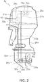
- FIG. 2 is a side view of the first outboard motor 3a.
- the first outboard motor 3a includes an engine 21a, a drive shaft 22a, a propeller shaft 23a, a shift mechanism 24a, an engine cover 25a and a housing 26a.
- the engine 21a generates the thrust for propelling the watercraft 1.
- the engine 21a is disposed inside the engine cover 25a.
- the engine 21a includes a crankshaft 27a.
- the crankshaft 27a extends in the vertical direction.
- the drive shaft 22a is connected to the crankshaft 27a.
- the drive shaft 22a extends in the vertical direction.
- the propeller shaft 23a extends in the back-and-forth direction.
- the propeller shaft 23a is connected to the drive shaft 22a through the shift mechanism 24a.
- a propeller 28a is connected to the propeller shaft 23a.
- the housing 26a is disposed below the engine cover 25a.
- the drive shaft 22a, the propeller shaft 23a and the shift mechanism 24a are disposed inside the housing 26a.
- the shift mechanism 24a switches the rotational direction of power to be transmitted from the drive shaft 22a to the propeller shaft 23a.
- the shift mechanism 24a includes a plurality of gears and a clutch that changes meshing of gears.
- the shift mechanism 24a includes a forward moving gear 29a, a rearward moving gear 30a and a clutch 31a.
- the forward moving gear 29a and the rearward moving gear 30a are meshed with a bevel gear 36a attached to the drive shaft 22a.
- the clutch 31a selectively causes either the forward moving gear 29a or the rearward moving gear 30a to be engaged with the propeller shaft 23a.
- the clutch 31a is set to be movable to a forward moving position, a rearward moving position and a neutral position.
- the clutch 31a When set in the forward moving position, the clutch 31a causes the forward moving gear 29a to be engaged with the propeller shaft 23a. Accordingly, the rotation of the drive shaft 22a is transmitted to the propeller shaft 23a so as to rotate the propeller shaft 23a in a forward moving direction.
- the clutch 31a When set in the rearward moving position, the clutch 31a causes the rearward moving gear 30a to be engaged with the propeller shaft 23a. Accordingly, the rotation of the drive shaft 22a is transmitted to the propeller shaft 23a so as to rotate the propeller shaft 23a in a rearward moving direction.
- the clutch 31a When set in the neutral position, the clutch 31a causes both the forward moving gear 29a and the rearward moving gear 30a from being disengaged from the propeller shaft 23a. Accordingly, the rotation of the drive shaft 22a is not transmitted to the propeller shaft 23a.
- the first outboard motor 3a includes a shift member 32a and a shift actuator 33a.
- the shift member 32a is connected to the clutch 31a.
- the shift member 32a moves the clutch 31a to one of the forward moving position, the rearward moving position and the neutral position.
- the shift member 32a is a rod.
- the shift member 32a is rotated in a predetermined direction, the clutch 31a is moved from the forward moving position to the rearward moving position via the neutral position.
- the shift member 32a is rotated reversely to the predetermined direction, the clutch 31a is moved from the rearward moving position to the forward moving position via the neutral position.
- the shift member 32a is not limited to the rod, and alternatively, may be another member such as a wire.
- the shift actuator 33a is connected to the shift member 32a and drives the shift member 32a.
- the shift actuator 33a is, for instance, an electric motor.
- the shift actuator 33a drives the shift member 32a so as to switch the clutch 31a to one of the forward moving position, the rearward moving position and the neutral position. In other words, the shift actuator 33a switches the shift mechanism 24a among a forward moving state, a rearward moving state and a neutral state.
- the first outboard motor 3a includes a throttle valve 34a and a throttle actuator 35a.
- the throttle valve 34a regulates the intake amount of the engine 21a.
- the throttle actuator 35a controls the opening degree of the throttle valve 34a.
- the throttle actuator 35a is, for instance, an electric motor.
- the first outboard motor 3a includes an engine ECU (Electronic Control Unit) 39a.
- the engine ECU 39a includes a processor such as a CPU and memories such as an RAM and a ROM.
- the engine ECU 39a stores a program and data for controlling the first outboard motor 3a.
- the engine ECU 39a is connected to the shift actuator 33a and the throttle actuator 35a in a communicable manner.
- the engine ECU 39a controls the shift actuator 33a so as to switch the shift mechanism 24a of the first outboard motor 3a among the forward moving state, the rearward moving state and the neutral state.
- the engine ECU 39a controls the throttle actuator 35a so as to control the rotational speed of the engine 21a.
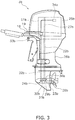
- FIG. 3 is a side view of the second outboard motor 3b.
- the second outboard motor 3b includes an engine 21b, a drive shaft 22b, a propeller shaft 23b, a shift mechanism 24b, an engine cover 25b, a housing 26b and a propeller 28b.
- the second outboard motor 3b is a type of outboard motor having a smaller horsepower than the first outboard motor 3a.
- the engine 21b of the second outboard motor 3b has a smaller displacement than the engine 21a of the first outboard motor 3a.
- the shift mechanism 24b of the second outboard motor 3b includes a forward moving gear 29b, a rearward moving gear 30b, a clutch 31b and a bevel gear 36b.
- These constituent elements of the second outboard motor 3b are basically the same as those of the first outboard motor 3a described above, and hence, the detailed explanation thereof will be omitted.
- the second outboard motor 3b includes a shift member 32b and a shift link mechanism 33b.
- the shift member 32b is connected to the clutch 31b of the shift mechanism 24b.
- the shift link mechanism 33b is connected to a shift cable 18 to be described.
- the shift link mechanism 33b transmits the motion of the shift cable 18 to the shift member 32b.
- the shift link mechanism 33b includes a mechanical element such as a cam, a gear or so forth, and transmits the motion of the shift cable 18 to the shift member 32b by the mechanical motion thereof.
- the shift member 32b when driven by the shift cable 18, moves the clutch 31b to one of the forward moving position, the rearward moving position and the neutral position.
- the second outboard motor 3b includes a throttle valve 34b.
- the throttle valve 34b regulates the intake amount of the engine 21b.
- the throttle valve 34b is connected to a throttle cable 19. In the second outboard motor 3b, the opening degree of the throttle valve 34b is controlled by the motion of the throttle cable 19.
- FIG. 4 is a schematic diagram of a vessel operating system 7 for the watercraft 1.
- the vessel operating system 7 includes a remote control 12, an actuator unit 13 and an operational switch portion 14.
- the remote control 12 is disposed at the operator seat 5.
- the remote control 12 includes an operating tool 15.
- the operating tool 15 is a member by which an operator operates both shifting and throttle opening degree in each of the first and second outboard motors 3a and 3b.
- the operating tool 15 is set to be movable among the forward moving position, the neutral position and the rearward moving position.
- the remote control 12 outputs an electric operating signal, which indicates operating both shifting and throttle opening degree, in accordance with the position of the operating tool 15.
- the operating tool 15 is, for instance, a lever.
- the operating tool 15 is not limited to the lever, and alternatively, may be another type of device such as a switch, a joystick, a touchscreen or so forth.
- the remote control 12 is connected to the engine ECU 39a of the first outboard motor 3a in a communicable manner.
- the remote control 12 is connected to the engine ECU 39a of the first outboard motor 3a through a first transmission path 16.
- the first transmission path 16 is an electric cable for transmitting an electric signal.
- the first transmission path 16 is a constituent element through which an electric operating signal, outputted from the remote control 12, is transmitted to the engine ECU 39a of the first outboard motor 3a.
- the first outboard motor 3a receives the electric operating signal from the remote control 12 through the first transmission path 16, and is controlled in accordance with the electric operating signal.
- the actuator unit 13 is connected to the remote control 12 through the first transmission path 16.
- the actuator unit 13 is connected to the second outboard motor 3b through a second transmission path 17.
- the second transmission path 17 includes the aforementioned shift cable 18 and throttle cable 19.
- the second transmission path 17 is a constituent element through which a mechanical operating amount is transmitted to the second outboard motor 3b based on operating the operating tool 15.
- the mechanical operating amount is indicated by the motion amount of the shift cable 18.
- the mechanical operating amount is indicated by the motion amount of the throttle cable 19.
- the mechanical operating amount is indicated by the motion amount of pushing and pulling each of the shift cable 18 and the throttle cable 19.
- the mechanical operating amount may be indicated by the amount of another type of motion such as rotation of each of the shift cable 18 and the throttle cable 19.
- the actuator unit 13 converts an electric operating amount, inputted thereto from the remote control 12 through the first transmission path 16, into a mechanical operating amount, and then transmits the mechanical operating amount to the second outboard motor 3b through the second transmission path 17.
- the second outboard motor 3b receives the mechanical operating amount through the second transmission path 17, and is controlled in accordance with the mechanical operating amount.
- the actuator unit 13 includes an actuator 41 and an actuator ECU 42.
- the actuator 41 is connected to the second transmission path 17.
- the actuator ECU 42 includes a processor such as a CPU and memories such as an RAM and an ROM.
- the actuator ECU 42 stores a program and data for controlling the actuator 41.
- the actuator ECU 42 is connected to the actuator 41 in a communicable manner.
- the actuator ECU 42 controls the actuator 41.
- FIG. 5 is a configuration diagram of the actuator 41.
- the actuator 41 includes a first movable member 43 and a first motor 44.
- the first movable member 43 is connected to the shift cable 18.
- the first motor 44 is connected to the first movable member 43 through a gear (not shown in the drawing), and drives the first movable member 43.
- the first motor 44 is, for instance, an electric motor.
- the first movable member 43 actuates the shift cable 18.
- the first movable member 43 is rotated about a rotational shaft 48 and thus pushes and pulls the shift cable 18.
- the actuator 41 includes a second movable member 45 and a second motor 46.
- the second movable member 45 is connected to the throttle cable 19.
- the second motor 46 is connected to the second movable member 45 through a gear (not shown in the drawing), and drives the second movable member 45.
- the second motor 46 is, for instance, an electric motor.
- the second movable member 45 actuates the throttle cable 19.
- the second movable member 45 is rotated about a rotational shaft 49 and thus pushes and pulls the throttle cable 19.
- first movable member 43 and/or the second movable member 45 may be provided to be linearly movable.
- the motion of the shift cable 18 and that of the throttle cable 19 are not limited to the push-and-pull motion, and alternatively, may be another type of motion such as rotation.
- the operational switch portion 14 switches which of the first and second outboard motors 3a and 3b should be operated by the operating tool 15.
- the operational switch portion 14 is connected to the actuator unit 13.
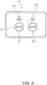
- FIG. 6 is a diagram showing the operational switch portion 14. As shown in FIG. 6 , the operational switch portion 14 includes a selection switch 47. The operator is capable of selecting which of operating the first outboard motor 3a and operating the second outboard motor 3b should be made active by operating the selection switch 47.
- the selection switch 47 is composed of a first switch 51 and a second switch 52.
- the operational switch portion 14 When the first switch 51 is pressed, the operational switch portion 14 outputs a command signal to make operating the first outboard motor 3a active.
- the second switch 52 When the second switch 52 is pressed, the operational switch portion 14 outputs a command signal to make operating the second outboard motor 3b active.
- the command signal, outputted from the operational switch portion 14, is transmitted to the actuator ECU 42.
- the operational switch portion 14 includes a first indicator 53 and a second indicator 54.
- the first indicator 53 is lit when operating the first outboard motor 3a is made active.
- the second indicator 54 is lit when operating the second outboard motor 3b is made active.
- the selection switch 47 is not limited to the push-button switch, and alternatively, may be another type of switch such as a slide switch or a rotary switch.
- the selection switch 47 may be a switch movable to a first position and a second position. When the selection switch 47 is herein set in the first position, operating the first outboard motor 3a is made active. When the selection switch 47 is herein set in the second position, operating the second outboard motor 3b is made active.
- the selection switch 47 may be a touchscreen switch.
- the electric operating signal, outputted from the operating tool 15, is transmitted to the engine ECU 39a of the first outboard motor 3a through the first transmission path 16.
- the engine ECU 39a in the first outboard motor 3a controls the shift actuator 33a such that the shift mechanism 24a in the first outboard motor 3a is switched from the neutral state to the forward moving state in accordance with the electric operating signal inputted thereto from the remote control 12.
- the engine ECU 39a controls the throttle actuator 35a such that the throttle opening degree is regulated in accordance with the operating amount of the operating tool 15.
- the engine ECU 39a controls the shift actuator 33a such that the shift mechanism 24a in the first outboard motor 3a is switched from the neutral state to the rearward moving state in accordance with the electric operating signal inputted thereto from the remote control 12. Additionally, in rearward movement, the engine ECU 39a similarly controls the throttle actuator 35a, as does in forward movement, such that the throttle operating degree is regulated in accordance with the operating amount of the operating tool 15.
- operating the second outboard motor 3b when operating the first outboard motor 3a is made active, operating the second outboard motor 3b is made inactive. For example, when operating the second outboard motor 3b is inactive, the shift mechanism 24b in the second outboard motor 3b is kept in the neutral state.
- the actuator ECU 42 When receiving the command signal to make operating the second outboard motor 3b active from the operational switch portion 14, the actuator ECU 42 computes the mechanical operating amount in accordance with the electric operating signal inputted thereto from the remote control 12, and controls the actuator 41 to output the mechanical operating amount to the second outboard motor 3b through the second transmission path 17.
- the actuator ECU 42 has operating amount information that defines the relation between the electric operating signal and the mechanical operating amount.
- the actuator ECU 42 converts the electric operating signal into the mechanical operating amount with reference to the operating amount information.
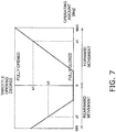
- FIG. 7 is a chart showing an example of the operating amount information.
- the horizontal axis indicates the operating amount of the operating tool 15 of the remote control 12.
- the operating amount is expressed by the rotational angle of the operating tool 15 from the neutral position.
- the operating amount may be another parameter such as the stroke amount of the operating tool 15 from the neutral position.
- the vertical axis indicates the throttle opening degree.
- the throttle opening degree corresponds to the motion amount of the throttle cable 19.
- the actuator ECU 42 When the operating tool 15 is operated from the neutral position toward the rearward moving position, the actuator ECU 42 causes the actuator 41 to actuate the shift cable 18 such that the shift mechanism 24a in the second outboard motor 3b is switched from the neutral state into the rearward moving state. As shown in FIG. 7 , when the operating amount of the operating tool 15 is "a2", the actuator ECU 42 sets a value "b2" corresponding to the operating amount "a2" as the throttle opening degree with reference to the operating amount information. The actuator ECU 42 causes the actuator 41 to actuate the throttle cable 19 such that the throttle opening degree of the engine 21b in the second outboard motor 3b is regulated to "b2".
- operating the first outboard motor 3a when operating the second outboard motor 3b is made active, operating the first outboard motor 3a is made inactive. For example, when operating the first outboard motor 3a is inactive, the shift mechanism 24a in the first outboard motor 3a is kept in the neutral state.
- the first outboard motor 3a which is of an electronically controlled type
- the second outboard motor 3b which is of a mechanically controlled type
- the common remote control 12 Therefore, it is not required to dispose different remote controls provided for the outboard motors, respectively, on the watercraft 1.
- the configuration of the operator seat 5 can be made simple.
- the second outboard motor 3b which is of a mechanically controlled type, is electronically controllable by the actuator unit 13. Therefore, the second outboard motor 3b is effectively controllable under the electronic control by making the aforementioned operating amount information suitable for the second outboard motor 3b.
- the watercraft 1 includes the first outboard motor 3a as only one electronically controlled outboard motor. However, the number of electronically controlled outboard motors may be two or greater. In the aforementioned preferred embodiment, the watercraft 1 includes the second outboard motor 3b as only one mechanically controlled outboard motor. However, the number of mechanically controlled outboard motors may be two or greater.
- the horsepower of the second outboard motor 3b is not limited to be smaller than that of the first outboard motor 3a, and alternatively, may be equivalent to or larger than that of the first outboard motor 3a.
- the structure of the actuator unit 13 is not limited to that described in the aforementioned preferred embodiment, and may be changed.
- the first transmission path 16 is not limited to the electric cable, and may be changed.
- the first transmission path 16 may be in the form of wireless communication.
- the second transmission path 17 is not limited to the cable, and may be changed.
- the second transmission path 17 may include other mechanical elements such as a rod, a gear and a cam.
- the electric operating signal, transmitted to the first outboard motor 3a through the first transmission path 16, is not limited to indicate both shifting and throttle opening degree, and alternatively, may indicate only shifting, only throttle opening degree, or another type of parameter such as the steering angle of the first outboard motor 3a.
- the mechanical operating amount, transmitted to the second outboard motor 3b through the second transmission path 17, is not limited to indicate both shifting and throttle opening degree, and alternatively, may indicate only shifting, only throttle opening degree, or another type of parameter such as the steering angle of the second outboard motor 3b.
- the configuration of controlling the second outboard motor 3b by the actuator unit 13 is not limited to that in the aforementioned preferred embodiment.
- the actuator unit 13 may cause the second outboard motor 3b to execute a vessel operating mode enabled by an electronically controlled outboard motor.
- the vessel operating mode includes, for instance, a fixed spot keeping mode and/or an autopilot mode.
- the fixed spot keeping mode is a mode for keeping the watercraft 1 in a predetermined position.
- the autopilot mode is a mode for keeping the vessel velocity of the watercraft 1 at a predetermined velocity.
- FIG. 8 is a schematic diagram of a vessel operating system 7a according to a first modification.
- the vessel operating system 7a according to the first modification includes a selector device 55 for vessel operating modes.
- the operator operates the selector device 55 to select one of the vessel operating modes.
- the selector device 55 outputs a signal indicating the selected one of the vessel operating modes.
- the signal, indicating the selected one of the vessel operating modes is inputted to the engine ECU 39a in the first outboard motor 3a.
- the signal, indicating the selected one of the vessel operating modes is inputted to the actuator unit 13 as well.
- the selector device 55 may include a mechanical switch, or alternatively, may be of a touchscreen type.
- the selector device 55 may be integrated with or separated from the remote control 12.
- the actuator unit 13 controls both shifting and the throttle opening degree of the second outboard motor 3b by outputting the mechanical operating amount to the second outboard motor 3b through the second transmission path 17 so as to keep the watercraft 1 in the predetermined position.
- the actuator unit 13 controls both shifting and the throttle opening degree of the second outboard motor 3b by outputting the mechanical operating amount to the second outboard motor 3b through the second transmission path 17 so as to keep the vessel velocity at the predetermined velocity.
- the operating amount information is not limited to the aforementioned operating amount information shown in FIG. 7 and may be changed.
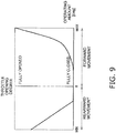
- FIG. 9 is a chart showing operating amount information according to modifications.
- the throttle opening degree linearly increases/reduces with increase/reduction in operating amount of the operating tool 15 in both forward movement and rearward movement.
- increase/reduction in throttle opening degree with respect to increase/reduction in operating amount is lesser in a low velocity range of forward movement than in a high velocity range of forward movement.
- minute regulation of the vessel velocity is made easy in the low velocity range.
- the actuator unit 13 may include the operating amount information shown in FIG. 9 instead of that shown in FIG. 7 .
- the actuator unit 13 may include both the operating amount information shown in FIG. 7 (first operating amount information) and the operating amount information shown in FIG. 9 (second operating amount information).
- the actuator unit 13 may selectively refer to one of the first operating amount information and the second operating amount information.
- one of the first operating amount information and the second operating amount information may be selected by the selector device 55 shown in FIG. 8 .
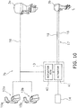
- FIG. 10 is a schematic diagram of a vessel operating system 7b according to a second modification.
- the vessel operating system 7b according to the second modification includes a first remote control 12a and a second remote control 12b.
- the first and second remote controls 12a and 12b may be disposed in different locations.
- the first remote control 12a may be disposed inside a cockpit of the watercraft 1
- the second remote control 12b may be disposed outside the cockpit of the watercraft 1.
- the first remote control 12a includes a first operating tool 15a.
- the second remote control 12b includes a second operating tool 15b.
- Each of the first and second remote controls 12a and 12b has a similar configuration to the aforementioned remote control 12.
- Each of the first and second operating tools 15a and 15b has a similar configuration to the aforementioned operating tool 15.
- the first and second remote controls 12a and 12b are connected to the first outboard motor 3a and the actuator unit 13 through the first transmission path 16.
- the actuator unit 13 may convert an electric operating signal, inputted thereto from either the first remote control 12a or the second remote control 12b through the first transmission path 16, into a mechanical operating amount and transmit the mechanical operating amount to the second outboard motor 3b through the second transmission path 17.
- the detailed configuration of controlling the second outboard motor 3b by the actuator unit 13 is similar to that in the aforementioned preferred embodiment.
- the shift mechanism 24b in the second outboard motor 3b when operating the first outboard motor 3a is made active, operating the second outboard motor 3b is made inactive and the shift mechanism 24b in the second outboard motor 3b is kept in the neutral state.
- the shift mechanism 24b when operating the first outboard motor 3a is made active, the shift mechanism 24b may be set in the forward moving state while the engine 21b in the second outboard motor 3b is stopped. Accordingly, the propeller 28b in the second outboard motor 3b can be inhibited from rotating along with the propeller 28a in the first outboard motor 3a.
Landscapes
- Engineering & Computer Science (AREA)
- Chemical & Material Sciences (AREA)
- Combustion & Propulsion (AREA)
- Mechanical Engineering (AREA)
- Ocean & Marine Engineering (AREA)
- General Engineering & Computer Science (AREA)
- Control Of Vehicle Engines Or Engines For Specific Uses (AREA)
- Control Of Throttle Valves Provided In The Intake System Or In The Exhaust System (AREA)
Abstract
Description
- The present invention relates to a watercraft and a system for operating the same.
- There is a type of watercraft including a plurality of different types of outboard motors. For example, as described in United States Patent No.
7,497,748 , there is a type of watercraft that includes a first outboard motor with a large horsepower as a main motor and a second outboard motor with a small horsepower as an auxiliary motor. When controlled by different systems, the first and second outboard motors are attached to a watercraft while being paired with tools for operating them, respectively. Therefore, the watercraft includes the first outboard motor, the tool for operating the first outboard motor (a first operating tool), the second outboard motor and the tool for operating the second outboard motor (a second operating tool). - For example, when the first outboard motor is controlled by an electric operating signal, the first operating tool outputs an electric signal, which indicates operating both shifting and throttle opening degree of the first outboard motor, to the first outboard motor through an electric cable. By contrast, when the second outboard motor is controlled by a mechanical operating amount, the second operating tool outputs a mechanical operating amount, which indicates operating both shifting and throttle opening degree of the second outboard motor, to the second outboard motor through, for instance, motions to push and pull a cable.
- However, as described above, when the watercraft is equipped with the plural operating tools that are associated with the plural outboard motors, respectively, a system for operating the watercraft is made complex, and operating each outboard motor is made cumbersome. In view of this, improvement has been demanded for a watercraft and a system for operating the watercraft such that a plurality of outboard motors are operable by configuring the system for operating the watercraft as simply as possible.
- Above-identified object is achieved by a watercraft according to
claim 1 and a vessel operating system according to claim 8. A watercraft according to a first aspect includes a vessel body, a first outboard motor, a second outboard motor, an operating tool, a first transmission path and a second transmission path. The first outboard motor is attached to a vessel body, receives an electric operating signal, and is controlled in accordance with the electric operating signal. The second outboard motor is attached to the vessel body, receives a mechanical operating amount, and is controlled in accordance with the mechanical operating amount. The operating tool operates shifting and a throttle opening degree of each of the first and second outboard motors. The first transmission path is a constituent element through which the electric operating signal is transmitted to the first outboard motor based on operating the operating tool. The second transmission path is a constituent element through which the mechanical operating amount is transmitted to the second outboard motor based on operating the operating tool. - A vessel operating system according to a second aspect includes a first outboard motor, a second outboard motor, an operating tool, a first transmission path and a second transmission path. The first outboard motor receives an electric operating signal and is controlled in accordance with the electric operating signal. The second outboard motor receives a mechanical operating amount and is controlled in accordance with the mechanical operating amount. The operating tool operates shifting and a throttle opening degree of each of the first and second outboard motors. The first transmission path is a constituent element through which the electric operating signal is transmitted to the first outboard motor based on operating the operating tool. The second transmission path is a constituent element through which the mechanical operating amount is transmitted to the second outboard motor based on operating the operating tool.
-
-
FIG. 1 is a schematic diagram of a watercraft according to a preferred embodiment. -
FIG. 2 is a side view of a first outboard motor. -
FIG. 3 is a side view of a second outboard motor. -
FIG. 4 is a schematic diagram of a system for operating the watercraft. -
FIG. 5 is a configuration diagram of an actuator. -
FIG. 6 is a configuration diagram of an operational switch portion. -
FIG. 7 is a chart showing an example of operating amount information. -
FIG. 8 is a schematic diagram of a system for operating a watercraft according to a first modification. -
FIG. 9 is a chart showing operating amount information according to modifications. -
FIG. 10 is a schematic diagram of a system for operating a watercraft according to a second modification. - A preferred embodiment will be hereinafter explained with reference to drawings.
FIG. 1 is a schematic diagram of awatercraft 1 according to the preferred embodiment. As shown inFIG. 1 , thewatercraft 1 includes avessel body 2, afirst outboard motor 3a and asecond outboard motor 3b. Thevessel body 2 includes anoperator seat 5. Theoperator seat 5 is provided with avessel operating device 6 including asteering wheel 11 and so forth. Each of the first andsecond outboard motors watercraft 1. Each of the first andsecond outboard motors vessel body 2. -
FIG. 2 is a side view of thefirst outboard motor 3a. Thefirst outboard motor 3a includes anengine 21a, adrive shaft 22a, apropeller shaft 23a, ashift mechanism 24a, anengine cover 25a and ahousing 26a. Theengine 21a generates the thrust for propelling thewatercraft 1. Theengine 21a is disposed inside theengine cover 25a. Theengine 21a includes acrankshaft 27a. Thecrankshaft 27a extends in the vertical direction. Thedrive shaft 22a is connected to thecrankshaft 27a. Thedrive shaft 22a extends in the vertical direction. - The
propeller shaft 23a extends in the back-and-forth direction. Thepropeller shaft 23a is connected to thedrive shaft 22a through theshift mechanism 24a. Apropeller 28a is connected to thepropeller shaft 23a. Thehousing 26a is disposed below theengine cover 25a. Thedrive shaft 22a, thepropeller shaft 23a and theshift mechanism 24a are disposed inside thehousing 26a. - The
shift mechanism 24a switches the rotational direction of power to be transmitted from thedrive shaft 22a to thepropeller shaft 23a. Theshift mechanism 24a includes a plurality of gears and a clutch that changes meshing of gears. For example, theshift mechanism 24a includes a forward movinggear 29a, a rearward movinggear 30a and aclutch 31a. The forward movinggear 29a and the rearward movinggear 30a are meshed with abevel gear 36a attached to thedrive shaft 22a. Theclutch 31a selectively causes either the forward movinggear 29a or the rearward movinggear 30a to be engaged with thepropeller shaft 23a. Theclutch 31a is set to be movable to a forward moving position, a rearward moving position and a neutral position. - When set in the forward moving position, the
clutch 31a causes the forward movinggear 29a to be engaged with thepropeller shaft 23a. Accordingly, the rotation of thedrive shaft 22a is transmitted to thepropeller shaft 23a so as to rotate thepropeller shaft 23a in a forward moving direction. When set in the rearward moving position, the clutch 31a causes the rearward movinggear 30a to be engaged with thepropeller shaft 23a. Accordingly, the rotation of thedrive shaft 22a is transmitted to thepropeller shaft 23a so as to rotate thepropeller shaft 23a in a rearward moving direction. When set in the neutral position, the clutch 31a causes both the forward movinggear 29a and the rearward movinggear 30a from being disengaged from thepropeller shaft 23a. Accordingly, the rotation of thedrive shaft 22a is not transmitted to thepropeller shaft 23a. - The first
outboard motor 3a includes ashift member 32a and ashift actuator 33a. Theshift member 32a is connected to the clutch 31a. When driven by theshift actuator 33a, theshift member 32a moves the clutch 31a to one of the forward moving position, the rearward moving position and the neutral position. For example, theshift member 32a is a rod. When theshift member 32a is rotated in a predetermined direction, the clutch 31a is moved from the forward moving position to the rearward moving position via the neutral position. When theshift member 32a is rotated reversely to the predetermined direction, the clutch 31a is moved from the rearward moving position to the forward moving position via the neutral position. However, theshift member 32a is not limited to the rod, and alternatively, may be another member such as a wire. - The
shift actuator 33a is connected to theshift member 32a and drives theshift member 32a. Theshift actuator 33a is, for instance, an electric motor. Theshift actuator 33a drives theshift member 32a so as to switch the clutch 31a to one of the forward moving position, the rearward moving position and the neutral position. In other words, theshift actuator 33a switches theshift mechanism 24a among a forward moving state, a rearward moving state and a neutral state. - The first
outboard motor 3a includes athrottle valve 34a and athrottle actuator 35a. Thethrottle valve 34a regulates the intake amount of theengine 21a. Thethrottle actuator 35a controls the opening degree of thethrottle valve 34a. Thethrottle actuator 35a is, for instance, an electric motor. - The first
outboard motor 3a includes an engine ECU (Electronic Control Unit) 39a. Theengine ECU 39a includes a processor such as a CPU and memories such as an RAM and a ROM. Theengine ECU 39a stores a program and data for controlling the firstoutboard motor 3a. Theengine ECU 39a is connected to theshift actuator 33a and thethrottle actuator 35a in a communicable manner. Theengine ECU 39a controls theshift actuator 33a so as to switch theshift mechanism 24a of the firstoutboard motor 3a among the forward moving state, the rearward moving state and the neutral state. Theengine ECU 39a controls thethrottle actuator 35a so as to control the rotational speed of theengine 21a. -
FIG. 3 is a side view of the secondoutboard motor 3b. The secondoutboard motor 3b includes anengine 21b, adrive shaft 22b, apropeller shaft 23b, ashift mechanism 24b, anengine cover 25b, ahousing 26b and apropeller 28b. The secondoutboard motor 3b is a type of outboard motor having a smaller horsepower than the firstoutboard motor 3a. For example, theengine 21b of the secondoutboard motor 3b has a smaller displacement than theengine 21a of the firstoutboard motor 3a. - The
shift mechanism 24b of the secondoutboard motor 3b includes a forward movinggear 29b, a rearward movinggear 30b, a clutch 31b and abevel gear 36b. These constituent elements of the secondoutboard motor 3b are basically the same as those of the firstoutboard motor 3a described above, and hence, the detailed explanation thereof will be omitted. - The second
outboard motor 3b includes ashift member 32b and ashift link mechanism 33b. Theshift member 32b is connected to the clutch 31b of theshift mechanism 24b. Theshift link mechanism 33b is connected to ashift cable 18 to be described. Theshift link mechanism 33b transmits the motion of theshift cable 18 to theshift member 32b. Theshift link mechanism 33b includes a mechanical element such as a cam, a gear or so forth, and transmits the motion of theshift cable 18 to theshift member 32b by the mechanical motion thereof. In the secondoutboard motor 3b, theshift member 32b, when driven by theshift cable 18, moves the clutch 31b to one of the forward moving position, the rearward moving position and the neutral position. - The second
outboard motor 3b includes athrottle valve 34b. Thethrottle valve 34b regulates the intake amount of theengine 21b. Thethrottle valve 34b is connected to athrottle cable 19. In the secondoutboard motor 3b, the opening degree of thethrottle valve 34b is controlled by the motion of thethrottle cable 19. -
FIG. 4 is a schematic diagram of a vessel operating system 7 for thewatercraft 1. As shown inFIG. 4 , the vessel operating system 7 includes aremote control 12, anactuator unit 13 and anoperational switch portion 14. Theremote control 12 is disposed at theoperator seat 5. Theremote control 12 includes an operatingtool 15. The operatingtool 15 is a member by which an operator operates both shifting and throttle opening degree in each of the first and secondoutboard motors - The operating
tool 15 is set to be movable among the forward moving position, the neutral position and the rearward moving position. Theremote control 12 outputs an electric operating signal, which indicates operating both shifting and throttle opening degree, in accordance with the position of the operatingtool 15. The operatingtool 15 is, for instance, a lever. However, the operatingtool 15 is not limited to the lever, and alternatively, may be another type of device such as a switch, a joystick, a touchscreen or so forth. - The
remote control 12 is connected to theengine ECU 39a of the firstoutboard motor 3a in a communicable manner. Theremote control 12 is connected to theengine ECU 39a of the firstoutboard motor 3a through afirst transmission path 16. For example, thefirst transmission path 16 is an electric cable for transmitting an electric signal. - The
first transmission path 16 is a constituent element through which an electric operating signal, outputted from theremote control 12, is transmitted to theengine ECU 39a of the firstoutboard motor 3a. The firstoutboard motor 3a receives the electric operating signal from theremote control 12 through thefirst transmission path 16, and is controlled in accordance with the electric operating signal. - The
actuator unit 13 is connected to theremote control 12 through thefirst transmission path 16. Theactuator unit 13 is connected to the secondoutboard motor 3b through asecond transmission path 17. Thesecond transmission path 17 includes theaforementioned shift cable 18 andthrottle cable 19. Thesecond transmission path 17 is a constituent element through which a mechanical operating amount is transmitted to the secondoutboard motor 3b based on operating the operatingtool 15. - The mechanical operating amount is indicated by the motion amount of the
shift cable 18. The mechanical operating amount is indicated by the motion amount of thethrottle cable 19. For example, the mechanical operating amount is indicated by the motion amount of pushing and pulling each of theshift cable 18 and thethrottle cable 19. However, the mechanical operating amount may be indicated by the amount of another type of motion such as rotation of each of theshift cable 18 and thethrottle cable 19. - The
actuator unit 13 converts an electric operating amount, inputted thereto from theremote control 12 through thefirst transmission path 16, into a mechanical operating amount, and then transmits the mechanical operating amount to the secondoutboard motor 3b through thesecond transmission path 17. The secondoutboard motor 3b receives the mechanical operating amount through thesecond transmission path 17, and is controlled in accordance with the mechanical operating amount. - Detailedly, the
actuator unit 13 includes anactuator 41 and anactuator ECU 42. Theactuator 41 is connected to thesecond transmission path 17. Theactuator ECU 42 includes a processor such as a CPU and memories such as an RAM and an ROM. Theactuator ECU 42 stores a program and data for controlling theactuator 41. Theactuator ECU 42 is connected to theactuator 41 in a communicable manner. Theactuator ECU 42 controls theactuator 41. -
FIG. 5 is a configuration diagram of theactuator 41. Theactuator 41 includes a firstmovable member 43 and afirst motor 44. The firstmovable member 43 is connected to theshift cable 18. Thefirst motor 44 is connected to the firstmovable member 43 through a gear (not shown in the drawing), and drives the firstmovable member 43. Thefirst motor 44 is, for instance, an electric motor. When driven by thefirst motor 44, the firstmovable member 43 actuates theshift cable 18. For example, when driven by thefirst motor 44, the firstmovable member 43 is rotated about arotational shaft 48 and thus pushes and pulls theshift cable 18. - The
actuator 41 includes a secondmovable member 45 and asecond motor 46. The secondmovable member 45 is connected to thethrottle cable 19. Thesecond motor 46 is connected to the secondmovable member 45 through a gear (not shown in the drawing), and drives the secondmovable member 45. Thesecond motor 46 is, for instance, an electric motor. When driven by thesecond motor 46, the secondmovable member 45 actuates thethrottle cable 19. For example, when driven by thesecond motor 46, the secondmovable member 45 is rotated about arotational shaft 49 and thus pushes and pulls thethrottle cable 19. - However, the first
movable member 43 and/or the secondmovable member 45 may be provided to be linearly movable. The motion of theshift cable 18 and that of thethrottle cable 19 are not limited to the push-and-pull motion, and alternatively, may be another type of motion such as rotation. - The
operational switch portion 14 switches which of the first and secondoutboard motors tool 15. Theoperational switch portion 14 is connected to theactuator unit 13.FIG. 6 is a diagram showing theoperational switch portion 14. As shown inFIG. 6 , theoperational switch portion 14 includes aselection switch 47. The operator is capable of selecting which of operating the firstoutboard motor 3a and operating the secondoutboard motor 3b should be made active by operating theselection switch 47. - The
selection switch 47 is composed of afirst switch 51 and asecond switch 52. When thefirst switch 51 is pressed, theoperational switch portion 14 outputs a command signal to make operating the firstoutboard motor 3a active. When thesecond switch 52 is pressed, theoperational switch portion 14 outputs a command signal to make operating the secondoutboard motor 3b active. The command signal, outputted from theoperational switch portion 14, is transmitted to theactuator ECU 42. - The
operational switch portion 14 includes afirst indicator 53 and asecond indicator 54. Thefirst indicator 53 is lit when operating the firstoutboard motor 3a is made active. Thesecond indicator 54 is lit when operating the secondoutboard motor 3b is made active. - It should be noted that the
selection switch 47 is not limited to the push-button switch, and alternatively, may be another type of switch such as a slide switch or a rotary switch. Theselection switch 47 may be a switch movable to a first position and a second position. When theselection switch 47 is herein set in the first position, operating the firstoutboard motor 3a is made active. When theselection switch 47 is herein set in the second position, operating the secondoutboard motor 3b is made active. Alternatively, theselection switch 47 may be a touchscreen switch. - When operating the first
outboard motor 3a is made active, the electric operating signal, outputted from the operatingtool 15, is transmitted to theengine ECU 39a of the firstoutboard motor 3a through thefirst transmission path 16. For example, when the operatingtool 15 is operated from the neutral position toward the forward moving position while operating the firstoutboard motor 3a is made active, theengine ECU 39a in the firstoutboard motor 3a controls theshift actuator 33a such that theshift mechanism 24a in the firstoutboard motor 3a is switched from the neutral state to the forward moving state in accordance with the electric operating signal inputted thereto from theremote control 12. Additionally, theengine ECU 39a controls thethrottle actuator 35a such that the throttle opening degree is regulated in accordance with the operating amount of the operatingtool 15. - When the operating
tool 15 is operated from the neutral position toward the rearward moving position while operating the firstoutboard motor 3a is made active, theengine ECU 39a controls theshift actuator 33a such that theshift mechanism 24a in the firstoutboard motor 3a is switched from the neutral state to the rearward moving state in accordance with the electric operating signal inputted thereto from theremote control 12. Additionally, in rearward movement, theengine ECU 39a similarly controls thethrottle actuator 35a, as does in forward movement, such that the throttle operating degree is regulated in accordance with the operating amount of the operatingtool 15. - It should be noted that when operating the first
outboard motor 3a is made active, operating the secondoutboard motor 3b is made inactive. For example, when operating the secondoutboard motor 3b is inactive, theshift mechanism 24b in the secondoutboard motor 3b is kept in the neutral state. - When receiving the command signal to make operating the second
outboard motor 3b active from theoperational switch portion 14, theactuator ECU 42 computes the mechanical operating amount in accordance with the electric operating signal inputted thereto from theremote control 12, and controls theactuator 41 to output the mechanical operating amount to the secondoutboard motor 3b through thesecond transmission path 17. - The
actuator ECU 42 has operating amount information that defines the relation between the electric operating signal and the mechanical operating amount. Theactuator ECU 42 converts the electric operating signal into the mechanical operating amount with reference to the operating amount information.FIG. 7 is a chart showing an example of the operating amount information. InFIG. 7 , the horizontal axis indicates the operating amount of the operatingtool 15 of theremote control 12. The operating amount is expressed by the rotational angle of the operatingtool 15 from the neutral position. However, the operating amount may be another parameter such as the stroke amount of the operatingtool 15 from the neutral position. The vertical axis indicates the throttle opening degree. The throttle opening degree corresponds to the motion amount of thethrottle cable 19. - Explanation will be hereinafter made regarding control of the
actuator unit 13 in a condition that operating the secondoutboard motor 3b is made active by theoperational switch portion 14. For example, when the operatingtool 15 is operated from the neutral position toward the forward moving position, theactuator ECU 42 causes theactuator 41 to actuate theshift cable 18 such that theshift mechanism 24a in the secondoutboard motor 3b is switched from the neutral state into the forward moving state. As shown inFIG. 7 , when the operating amount of the operatingtool 15 is "a1", theactuator ECU 42 sets a value "b1" corresponding to the operating amount "a1", as the throttle opening degree with reference to the operating amount information. Theactuator ECU 42 causes theactuator 41 to actuate thethrottle cable 19 such that the throttle opening degree of theengine 21b in the secondoutboard motor 3b is regulated to "b1". - When the operating
tool 15 is operated from the neutral position toward the rearward moving position, theactuator ECU 42 causes theactuator 41 to actuate theshift cable 18 such that theshift mechanism 24a in the secondoutboard motor 3b is switched from the neutral state into the rearward moving state. As shown inFIG. 7 , when the operating amount of the operatingtool 15 is "a2", theactuator ECU 42 sets a value "b2" corresponding to the operating amount "a2" as the throttle opening degree with reference to the operating amount information. Theactuator ECU 42 causes theactuator 41 to actuate thethrottle cable 19 such that the throttle opening degree of theengine 21b in the secondoutboard motor 3b is regulated to "b2". - It should be noted that when operating the second
outboard motor 3b is made active, operating the firstoutboard motor 3a is made inactive. For example, when operating the firstoutboard motor 3a is inactive, theshift mechanism 24a in the firstoutboard motor 3a is kept in the neutral state. - In the
watercraft 1 and the vessel operating system 7 according to the present preferred embodiment explained above, the firstoutboard motor 3a, which is of an electronically controlled type, and the secondoutboard motor 3b, which is of a mechanically controlled type, can be operated by the commonremote control 12. Therefore, it is not required to dispose different remote controls provided for the outboard motors, respectively, on thewatercraft 1. Hence, the configuration of theoperator seat 5 can be made simple. - For example, in long-distance movement of the
watercraft 1 that includes the firstoutboard motor 3a as a main motor and the secondoutboard motor 3b as an auxiliary motor, operating the firstoutboard motor 3a is made active whereby the firstoutboard motor 3a is operable by theremote control 12. By contrast, in minute positional adjustment or short-distance movement of thewatercraft 1, operating the secondoutboard motor 3b is made active whereby the secondoutboard motor 3b is operable by theremote control 12. - Additionally, in the
watercraft 1 and the vessel operating system 7 according to the present preferred embodiment, the secondoutboard motor 3b, which is of a mechanically controlled type, is electronically controllable by theactuator unit 13. Therefore, the secondoutboard motor 3b is effectively controllable under the electronic control by making the aforementioned operating amount information suitable for the secondoutboard motor 3b. - One preferred embodiment of the present invention has been explained above. However, the present invention is not limited to the aforementioned preferred embodiment, and a variety of changes can be made without departing from the gist of the present invention.
- In the aforementioned preferred embodiment, the
watercraft 1 includes the firstoutboard motor 3a as only one electronically controlled outboard motor. However, the number of electronically controlled outboard motors may be two or greater. In the aforementioned preferred embodiment, thewatercraft 1 includes the secondoutboard motor 3b as only one mechanically controlled outboard motor. However, the number of mechanically controlled outboard motors may be two or greater. The horsepower of the secondoutboard motor 3b is not limited to be smaller than that of the firstoutboard motor 3a, and alternatively, may be equivalent to or larger than that of the firstoutboard motor 3a. - The structure of the
actuator unit 13 is not limited to that described in the aforementioned preferred embodiment, and may be changed. Thefirst transmission path 16 is not limited to the electric cable, and may be changed. For example, thefirst transmission path 16 may be in the form of wireless communication. Thesecond transmission path 17 is not limited to the cable, and may be changed. For example, thesecond transmission path 17 may include other mechanical elements such as a rod, a gear and a cam. - The electric operating signal, transmitted to the first
outboard motor 3a through thefirst transmission path 16, is not limited to indicate both shifting and throttle opening degree, and alternatively, may indicate only shifting, only throttle opening degree, or another type of parameter such as the steering angle of the firstoutboard motor 3a. Likewise, the mechanical operating amount, transmitted to the secondoutboard motor 3b through thesecond transmission path 17, is not limited to indicate both shifting and throttle opening degree, and alternatively, may indicate only shifting, only throttle opening degree, or another type of parameter such as the steering angle of the secondoutboard motor 3b. - The configuration of controlling the second
outboard motor 3b by theactuator unit 13 is not limited to that in the aforementioned preferred embodiment. For example, theactuator unit 13 may cause the secondoutboard motor 3b to execute a vessel operating mode enabled by an electronically controlled outboard motor. The vessel operating mode includes, for instance, a fixed spot keeping mode and/or an autopilot mode. The fixed spot keeping mode is a mode for keeping thewatercraft 1 in a predetermined position. The autopilot mode is a mode for keeping the vessel velocity of thewatercraft 1 at a predetermined velocity. -
FIG. 8 is a schematic diagram of avessel operating system 7a according to a first modification. Thevessel operating system 7a according to the first modification includes aselector device 55 for vessel operating modes. The operator operates theselector device 55 to select one of the vessel operating modes. Theselector device 55 outputs a signal indicating the selected one of the vessel operating modes. The signal, indicating the selected one of the vessel operating modes, is inputted to theengine ECU 39a in the firstoutboard motor 3a. The signal, indicating the selected one of the vessel operating modes, is inputted to theactuator unit 13 as well. - The
selector device 55 may include a mechanical switch, or alternatively, may be of a touchscreen type. Theselector device 55 may be integrated with or separated from theremote control 12. - When the fixed position keeping mode is selected by the
selector device 55 while operating the secondoutboard motor 3b is made active, theactuator unit 13 controls both shifting and the throttle opening degree of the secondoutboard motor 3b by outputting the mechanical operating amount to the secondoutboard motor 3b through thesecond transmission path 17 so as to keep thewatercraft 1 in the predetermined position. When the autopilot mode is selected by theselector device 55 while operating the secondoutboard motor 3b is made active, theactuator unit 13 controls both shifting and the throttle opening degree of the secondoutboard motor 3b by outputting the mechanical operating amount to the secondoutboard motor 3b through thesecond transmission path 17 so as to keep the vessel velocity at the predetermined velocity. - The operating amount information is not limited to the aforementioned operating amount information shown in
FIG. 7 and may be changed. For example,FIG. 9 is a chart showing operating amount information according to modifications. In the operating amount information shown inFIG. 7 , the throttle opening degree linearly increases/reduces with increase/reduction in operating amount of the operatingtool 15 in both forward movement and rearward movement. By contrast, in the operating amount information shown inFIG. 9 , increase/reduction in throttle opening degree with respect to increase/reduction in operating amount is lesser in a low velocity range of forward movement than in a high velocity range of forward movement. When theactuator unit 13 refers to the operating amount information herein described, minute regulation of the vessel velocity is made easy in the low velocity range. - It should be noted that the
actuator unit 13 may include the operating amount information shown inFIG. 9 instead of that shown inFIG. 7 . Alternatively, theactuator unit 13 may include both the operating amount information shown inFIG. 7 (first operating amount information) and the operating amount information shown inFIG. 9 (second operating amount information). Theactuator unit 13 may selectively refer to one of the first operating amount information and the second operating amount information. Similarly to the aforementioned vessel operating modes, one of the first operating amount information and the second operating amount information may be selected by theselector device 55 shown inFIG. 8 . - In the aforementioned preferred embodiment, one
remote control 12 is provided, but alternatively, two or moreremote controls 12 may be provided.FIG. 10 is a schematic diagram of avessel operating system 7b according to a second modification. Thevessel operating system 7b according to the second modification includes a firstremote control 12a and a secondremote control 12b. The first and secondremote controls remote control 12a may be disposed inside a cockpit of thewatercraft 1, whereas the secondremote control 12b may be disposed outside the cockpit of thewatercraft 1. - The first
remote control 12a includes afirst operating tool 15a. The secondremote control 12b includes asecond operating tool 15b. Each of the first and secondremote controls remote control 12. Each of the first andsecond operating tools aforementioned operating tool 15. The first and secondremote controls outboard motor 3a and theactuator unit 13 through thefirst transmission path 16. - The
actuator unit 13 may convert an electric operating signal, inputted thereto from either the firstremote control 12a or the secondremote control 12b through thefirst transmission path 16, into a mechanical operating amount and transmit the mechanical operating amount to the secondoutboard motor 3b through thesecond transmission path 17. The detailed configuration of controlling the secondoutboard motor 3b by theactuator unit 13 is similar to that in the aforementioned preferred embodiment. - In the aforementioned preferred embodiment, when operating the first
outboard motor 3a is made active, operating the secondoutboard motor 3b is made inactive and theshift mechanism 24b in the secondoutboard motor 3b is kept in the neutral state. However, when operating the firstoutboard motor 3a is made active, theshift mechanism 24b may be set in the forward moving state while theengine 21b in the secondoutboard motor 3b is stopped. Accordingly, thepropeller 28b in the secondoutboard motor 3b can be inhibited from rotating along with thepropeller 28a in the firstoutboard motor 3a.
Claims (14)
- A watercraft (1) comprising:a vessel body (2);a first outboard motor (3a) attached to the vessel body (2), the first outboard motor (3a) being configured to receive an electric operating signal, the first outboard motor (3a) being configured to be controlled in accordance with the electric operating signal;a second outboard motor (3b) attached to the vessel body (2), the second outboard motor (3b) being configured to receive a mechanical operating amount, the second outboard motor (3b) being configured to be controlled in accordance with the mechanical operating amount;an operating tool (15, 15a) configured to operate shifting and a throttle opening degree of each of the first (3a) and second (3b) outboard motors;a first transmission path (16) through which the electric operating signal is configured to be transmitted to the first outboard motor (3a) based on operating the operating tool (15, 15a); anda second transmission path (17) through which the mechanical operating amount is configured to be transmitted to the second outboard motor based on operating the operating tool (15, 15a).
- The watercraft (1) according to claim 1, further comprising:an actuator unit (13) including an actuator (41) and a controller (42), the actuator (41) being connected to the second transmission path (17), the controller (42) being configured to control the actuator (41), whereinthe operating tool (15, 15a) is configured to output the electric operating signal indicating operating the shifting and the throttle operating degree,the controller (42) is configured to receive the electric operating signal from the operating tool (15), andthe controller (42) is configured to control the actuator (41) to output the mechanical operating amount in accordance with the electric operating signal.
- The watercraft (1) according to claim 2, wherein the controller (42) includes operating amount information defining a relation between the electric operating signal and the mechanical operating amount.
- The watercraft (1) according to claim 2, further comprising:
an operational switch portion (14) configured to switch which of the first (3a) and second outboard (3b) motors is operated by the operating tool (15, 15a). - The watercraft (1) according to claim 4, wherein the operational switch portion (14) is connected to the actuator unit (13).
- The watercraft (1) according to claim 4, wherein
the controller (42) is configured to output the electric operating signal inputted thereto from the operating tool (15, 15a) to the first outboard motor (3a) through the first transmission path (16) when operating the first outboard motor (3a) is made active by the operational switch portion (14), and
the controller (42) is configured to compute the mechanical operating amount in accordance with the electric operating signal inputted thereto from the operating tool (15, 15a) and is configured to control the actuator (41) to output the mechanical operating amount to the second outboard motor (3b) through the second transmission path (17) when operating the second outboard motor (3b) is made active by the operational switch portion (14). - The watercraft (1) according to claim 2, further comprising:a second operating tool (15b) configured to operate the shifting and the throttle opening degree of the each of the first (3a) and second (3b) outboard motors, whereinthe second operating tool (15b) is connected to the actuator unit (13), the second operating tool (15b) being configured to output the electric operating signal indicating the shifting and the throttle opening degree,the controller (42) is configured to receive the electric operating signal from the second operating tool (15b), andthe controller (42) is configured to control the actuator (41) to output the mechanical operating amount in accordance with the electric operating signal inputted thereto from the second operating tool (15b).
- A vessel operating system (7, 7a, 7b) comprising:a first outboard motor (3a) configured to receive an electric operating signal, the first outboard motor (3a) being configured to be controlled in accordance with the electric operating signal;a second outboard motor (3b) configured to receive a mechanical operating amount, the second outboard motor (3b) being configured to be controlled in accordance with the mechanical operating amount;an operating tool (15, 15a) configured to operate shifting and a throttle opening degree of each of the first (3a) and second (3b) outboard motors;a first transmission path (16) through which the electric operating signal is configured to be transmitted to the first outboard motor (3a) based on operating the operating tool (15, 15a); anda second transmission path (17) through which the mechanical operating amount is configured to be transmitted to the second outboard motor (3b) based on operating the operating tool (15, 15a).
- A vessel operating system (7, 7a, 7b) according to claim 8, further comprising:an actuator unit (13) including an actuator (41) and a controller (42), the actuator (41) being configured to be connected to the second transmission path (17), the controller (42) being configured to control the actuator (41), whereinthe operating tool (15) is configured to output the electric operating signal indicating operating the shifting and the throttle operating degree,the controller (42) is configured to receive the electric operating signal from the operating tool (15, 15a), andthe controller (42) is configured to control the actuator (41) to output the mechanical operating amount in accordance with the electric operating signal.
- The vessel operating system (7, 7a, 7b) according to claim 9, wherein the controller (42) includes operating amount information defining a relation between the electric operating signal and the mechanical operating amount.
- The vessel operating system (7, 7a, 7b) according to claim 9, further comprising:
an operational switch portion (14) configured to switch which of the first (3a) and second outboard (3b) motors is operated by the operating tool. - The vessel operating system (7, 7a, 7b) according to claim 11, wherein the operational switch portion (14) is connected to the actuator unit (13).
- The vessel operating system (7, 7a, 7b) according to claim 11, wherein
the controller (42) is configured to output the electric operating signal inputted thereto from the operating tool (15, 15a) to the first outboard motor (3a) through the first transmission path (16) when operating the first outboard motor (3a) is made active by the operational switch portion (14), and
the controller (42) is configured to compute the mechanical operating amount in accordance with the electric operating signal inputted thereto from the operating tool (15, 15a) and is configured to control the actuator (41) to output the mechanical operating amount to the second outboard motor (3b) through the second transmission path (17) when operating the second outboard motor (3b) is made active by the operational switch portion (14). - The vessel operating system (7b) according to claim 9, further comprising:a second operating tool (15b) configured to operate the shifting and the throttle opening degree of the each of the first (3a) and second (3b) outboard motors, whereinthe second operating tool (15b) is connected to the actuator unit (13), the second operating tool (15b) being configured to output the electric operating signal indicating the shifting and the throttle opening degree,the controller (42) is configured to receive the electric operating signal from the second operating tool (15b), andthe controller (42) is configured to control the actuator (41) to output the mechanical operating amount in accordance with the electric operating signal inputted thereto from the second operating tool (15b).
Applications Claiming Priority (1)
| Application Number | Priority Date | Filing Date | Title |
|---|---|---|---|
| JP2018093723A JP7117895B2 (en) | 2018-05-15 | 2018-05-15 | Ships and ship maneuvering systems |
Publications (2)
| Publication Number | Publication Date |
|---|---|
| EP3569493A1 true EP3569493A1 (en) | 2019-11-20 |
| EP3569493B1 EP3569493B1 (en) | 2023-12-20 |
Family
ID=66041206
Family Applications (1)
| Application Number | Title | Priority Date | Filing Date |
|---|---|---|---|
| EP19166170.1A Active EP3569493B1 (en) | 2018-05-15 | 2019-03-29 | Watercraft and system for operating same |
Country Status (3)
| Country | Link |
|---|---|
| US (1) | US10612461B2 (en) |
| EP (1) | EP3569493B1 (en) |
| JP (1) | JP7117895B2 (en) |
Cited By (1)
| Publication number | Priority date | Publication date | Assignee | Title |
|---|---|---|---|---|
| EP4201802A1 (en) * | 2021-12-24 | 2023-06-28 | Yamaha Hatsudoki Kabushiki Kaisha | Marine propulsion system and marine vessel with a marine propulsion system |
Families Citing this family (11)
| Publication number | Priority date | Publication date | Assignee | Title |
|---|---|---|---|---|
| US11347223B1 (en) * | 2018-10-05 | 2022-05-31 | Brunswick Corporation | Marine propulsion system and method for preventing collision of marine propulsion devices |
| USD967271S1 (en) | 2020-11-02 | 2022-10-18 | Brunswick Corporation | Remote control for a marine vessel |
| USD951168S1 (en) * | 2020-11-02 | 2022-05-10 | Brunswick Corporation | Remote control for a marine vessel |
| USD967270S1 (en) | 2020-11-02 | 2022-10-18 | Brunswick Corporation | Remote control for a marine vessel |
| JP7564796B2 (en) | 2021-09-30 | 2024-10-09 | 株式会社ハイレックスコーポレーション | Actuators and Cable Assemblies |
| JP2023068785A (en) * | 2021-11-04 | 2023-05-18 | ヤマハ発動機株式会社 | Ship propulsion systems and ships |
| JP2023094870A (en) * | 2021-12-24 | 2023-07-06 | ヤマハ発動機株式会社 | Ship propulsion systems and ships |
| CN116767477A (en) * | 2022-03-10 | 2023-09-19 | 广东逸动科技有限公司 | Vehicle, multi-power control system, control method and storage medium thereof |
| USD1023856S1 (en) | 2022-06-09 | 2024-04-23 | Brunswick Corporation | Remote control for a marine vessel |
| USD1015252S1 (en) | 2022-06-15 | 2024-02-20 | Brunswick Corporation | Remote control for a marine vessel |
| USD1006707S1 (en) | 2022-06-15 | 2023-12-05 | Brunswick Corporation | Remote control for a marine vessel |
Citations (4)
| Publication number | Priority date | Publication date | Assignee | Title |
|---|---|---|---|---|
| JPS5647398A (en) * | 1979-09-28 | 1981-04-30 | Toohatsu Kk | Operating apparatus for twin outboard engines |
| JP3386521B2 (en) * | 1993-07-05 | 2003-03-17 | 三信工業株式会社 | Remote control device for ship propulsion |
| JP2006347499A (en) * | 2005-06-20 | 2006-12-28 | Yamaha Motor Co Ltd | Ship |
| US7497748B2 (en) | 2007-01-23 | 2009-03-03 | Johnson Outdoors Inc. | Boat control system with return to center steering command |
Family Cites Families (5)
| Publication number | Priority date | Publication date | Assignee | Title |
|---|---|---|---|---|
| JP4127490B2 (en) | 2002-07-22 | 2008-07-30 | ヤマハマリン株式会社 | Ship engine starter |
| JP4430474B2 (en) * | 2004-07-15 | 2010-03-10 | ヤマハ発動機株式会社 | Ship maneuvering method and maneuvering device |
| JP4639111B2 (en) | 2005-04-22 | 2011-02-23 | 本田技研工業株式会社 | Outboard motor control device |
| JP4666492B2 (en) * | 2005-10-07 | 2011-04-06 | ヤマハ発動機株式会社 | Ship |
| JP2013163439A (en) * | 2012-02-10 | 2013-08-22 | Yamaha Motor Co Ltd | Outboard motor control system |
-
2018
- 2018-05-15 JP JP2018093723A patent/JP7117895B2/en active Active
- 2018-11-28 US US16/202,336 patent/US10612461B2/en active Active
-
2019
- 2019-03-29 EP EP19166170.1A patent/EP3569493B1/en active Active
Patent Citations (4)
| Publication number | Priority date | Publication date | Assignee | Title |
|---|---|---|---|---|
| JPS5647398A (en) * | 1979-09-28 | 1981-04-30 | Toohatsu Kk | Operating apparatus for twin outboard engines |
| JP3386521B2 (en) * | 1993-07-05 | 2003-03-17 | 三信工業株式会社 | Remote control device for ship propulsion |
| JP2006347499A (en) * | 2005-06-20 | 2006-12-28 | Yamaha Motor Co Ltd | Ship |
| US7497748B2 (en) | 2007-01-23 | 2009-03-03 | Johnson Outdoors Inc. | Boat control system with return to center steering command |
Cited By (2)
| Publication number | Priority date | Publication date | Assignee | Title |
|---|---|---|---|---|
| EP4201802A1 (en) * | 2021-12-24 | 2023-06-28 | Yamaha Hatsudoki Kabushiki Kaisha | Marine propulsion system and marine vessel with a marine propulsion system |
| US12420899B2 (en) | 2021-12-24 | 2025-09-23 | Yamaha Hatsudoki Kabushiki Kaisha | Marine propulsion system and marine vessel |
Also Published As
| Publication number | Publication date |
|---|---|
| US20190353093A1 (en) | 2019-11-21 |
| JP2019199128A (en) | 2019-11-21 |
| EP3569493B1 (en) | 2023-12-20 |
| US10612461B2 (en) | 2020-04-07 |
| JP7117895B2 (en) | 2022-08-15 |
Similar Documents
| Publication | Publication Date | Title |
|---|---|---|
| EP3569493B1 (en) | Watercraft and system for operating same | |
| EP2716541B1 (en) | Boat propulsion system and method for controlling boat propulsion unit | |
| US7762858B2 (en) | Propulsion system for boat | |
| EP3613663A1 (en) | Hybrid type vessel propulsion apparatus | |
| US6280269B1 (en) | Operator display panel control by throttle mechanism switch manipulation | |
| US20170285645A1 (en) | Watercraft steering system and watercraft | |
| US20140303809A1 (en) | Remote control device for vessel and remote control method for vessel propulsion device | |
| US9545987B1 (en) | Traction control systems and methods for marine vessels | |
| JP2017218016A (en) | Ship propulsion machine | |
| US20060240720A1 (en) | Outboard motor control system | |
| EP2727817B1 (en) | Ship maneuvering device | |
| US6293838B1 (en) | Marine propulsion system and method for controlling engine and/or transmission operation | |
| KR102559264B1 (en) | Remote controlling device for shift lever of ship and shift controlling apparatus having the same | |
| US12077272B2 (en) | System for and method of controlling watercraft including marine propulsion device | |
| JP2000006891A (en) | Wireless control device for marine vessel | |
| US11136101B2 (en) | Boat speed control device and boat maneuvering system | |
| US10399656B2 (en) | Remote control system of boat propulsion device | |
| JP2021146755A (en) | Control system for ship propulsion machine, and method for switching drive source of ship propulsion machine | |
| JP2021130376A (en) | Ship propulsion system and control method | |
| JP4639090B2 (en) | Outboard motor shift device | |
| EP2492186B1 (en) | Power transmission device of outboard motor | |
| JP2006062480A (en) | Remote control device for outboard motor | |
| US12491978B2 (en) | Marine propulsion device with simplified wiring of power lines | |
| US20250313324A1 (en) | Marine propulsion device | |
| JP2006062478A (en) | Remote control device for outboard motor |
Legal Events
| Date | Code | Title | Description |
|---|---|---|---|
| PUAI | Public reference made under article 153(3) epc to a published international application that has entered the european phase |
Free format text: ORIGINAL CODE: 0009012 |
|
| STAA | Information on the status of an ep patent application or granted ep patent |
Free format text: STATUS: THE APPLICATION HAS BEEN PUBLISHED |
|
| AK | Designated contracting states |
Kind code of ref document: A1 Designated state(s): AL AT BE BG CH CY CZ DE DK EE ES FI FR GB GR HR HU IE IS IT LI LT LU LV MC MK MT NL NO PL PT RO RS SE SI SK SM TR |
|
| AX | Request for extension of the european patent |
Extension state: BA ME |
|
| STAA | Information on the status of an ep patent application or granted ep patent |
Free format text: STATUS: REQUEST FOR EXAMINATION WAS MADE |
|
| 17P | Request for examination filed |
Effective date: 20200310 |
|
| RBV | Designated contracting states (corrected) |
Designated state(s): AL AT BE BG CH CY CZ DE DK EE ES FI FR GB GR HR HU IE IS IT LI LT LU LV MC MK MT NL NO PL PT RO RS SE SI SK SM TR |
|
| STAA | Information on the status of an ep patent application or granted ep patent |
Free format text: STATUS: EXAMINATION IS IN PROGRESS |
|
| 17Q | First examination report despatched |
Effective date: 20201125 |
|
| GRAP | Despatch of communication of intention to grant a patent |
Free format text: ORIGINAL CODE: EPIDOSNIGR1 |
|
| STAA | Information on the status of an ep patent application or granted ep patent |
Free format text: STATUS: GRANT OF PATENT IS INTENDED |
|
| INTG | Intention to grant announced |
Effective date: 20230406 |
|
| GRAJ | Information related to disapproval of communication of intention to grant by the applicant or resumption of examination proceedings by the epo deleted |
Free format text: ORIGINAL CODE: EPIDOSDIGR1 |
|
| P01 | Opt-out of the competence of the unified patent court (upc) registered |
Effective date: 20230601 |
|
| STAA | Information on the status of an ep patent application or granted ep patent |
Free format text: STATUS: EXAMINATION IS IN PROGRESS |
|
| INTC | Intention to grant announced (deleted) | ||
| GRAP | Despatch of communication of intention to grant a patent |
Free format text: ORIGINAL CODE: EPIDOSNIGR1 |
|
| STAA | Information on the status of an ep patent application or granted ep patent |
Free format text: STATUS: GRANT OF PATENT IS INTENDED |
|
| INTG | Intention to grant announced |
Effective date: 20230828 |
|
| GRAS | Grant fee paid |
Free format text: ORIGINAL CODE: EPIDOSNIGR3 |
|
| GRAA | (expected) grant |
Free format text: ORIGINAL CODE: 0009210 |
|
| STAA | Information on the status of an ep patent application or granted ep patent |
Free format text: STATUS: THE PATENT HAS BEEN GRANTED |
|
| AK | Designated contracting states |
Kind code of ref document: B1 Designated state(s): AL AT BE BG CH CY CZ DE DK EE ES FI FR GB GR HR HU IE IS IT LI LT LU LV MC MK MT NL NO PL PT RO RS SE SI SK SM TR |
|
| REG | Reference to a national code |
Ref country code: GB Ref legal event code: FG4D |
|
| REG | Reference to a national code |
Ref country code: DE Ref legal event code: R096 Ref document number: 602019043469 Country of ref document: DE |
|
| REG | Reference to a national code |
Ref country code: CH Ref legal event code: EP |
|
| REG | Reference to a national code |
Ref country code: IE Ref legal event code: FG4D |
|
| PG25 | Lapsed in a contracting state [announced via postgrant information from national office to epo] |
Ref country code: GR Free format text: LAPSE BECAUSE OF FAILURE TO SUBMIT A TRANSLATION OF THE DESCRIPTION OR TO PAY THE FEE WITHIN THE PRESCRIBED TIME-LIMIT Effective date: 20240321 |
|
| REG | Reference to a national code |
Ref country code: LT Ref legal event code: MG9D |
|
| PG25 | Lapsed in a contracting state [announced via postgrant information from national office to epo] |
Ref country code: LT Free format text: LAPSE BECAUSE OF FAILURE TO SUBMIT A TRANSLATION OF THE DESCRIPTION OR TO PAY THE FEE WITHIN THE PRESCRIBED TIME-LIMIT Effective date: 20231220 |
|
| REG | Reference to a national code |
Ref country code: NL Ref legal event code: MP Effective date: 20231220 |
|
| PG25 | Lapsed in a contracting state [announced via postgrant information from national office to epo] |
Ref country code: ES Free format text: LAPSE BECAUSE OF FAILURE TO SUBMIT A TRANSLATION OF THE DESCRIPTION OR TO PAY THE FEE WITHIN THE PRESCRIBED TIME-LIMIT Effective date: 20231220 |
|
| PG25 | Lapsed in a contracting state [announced via postgrant information from national office to epo] |
Ref country code: LT Free format text: LAPSE BECAUSE OF FAILURE TO SUBMIT A TRANSLATION OF THE DESCRIPTION OR TO PAY THE FEE WITHIN THE PRESCRIBED TIME-LIMIT Effective date: 20231220 Ref country code: GR Free format text: LAPSE BECAUSE OF FAILURE TO SUBMIT A TRANSLATION OF THE DESCRIPTION OR TO PAY THE FEE WITHIN THE PRESCRIBED TIME-LIMIT Effective date: 20240321 Ref country code: FI Free format text: LAPSE BECAUSE OF FAILURE TO SUBMIT A TRANSLATION OF THE DESCRIPTION OR TO PAY THE FEE WITHIN THE PRESCRIBED TIME-LIMIT Effective date: 20231220 Ref country code: ES Free format text: LAPSE BECAUSE OF FAILURE TO SUBMIT A TRANSLATION OF THE DESCRIPTION OR TO PAY THE FEE WITHIN THE PRESCRIBED TIME-LIMIT Effective date: 20231220 Ref country code: BG Free format text: LAPSE BECAUSE OF FAILURE TO SUBMIT A TRANSLATION OF THE DESCRIPTION OR TO PAY THE FEE WITHIN THE PRESCRIBED TIME-LIMIT Effective date: 20240320 |
|
| REG | Reference to a national code |
Ref country code: AT Ref legal event code: MK05 Ref document number: 1642258 Country of ref document: AT Kind code of ref document: T Effective date: 20231220 |
|
| PG25 | Lapsed in a contracting state [announced via postgrant information from national office to epo] |
Ref country code: NL Free format text: LAPSE BECAUSE OF FAILURE TO SUBMIT A TRANSLATION OF THE DESCRIPTION OR TO PAY THE FEE WITHIN THE PRESCRIBED TIME-LIMIT Effective date: 20231220 |
|
| PG25 | Lapsed in a contracting state [announced via postgrant information from national office to epo] |
Ref country code: SE Free format text: LAPSE BECAUSE OF FAILURE TO SUBMIT A TRANSLATION OF THE DESCRIPTION OR TO PAY THE FEE WITHIN THE PRESCRIBED TIME-LIMIT Effective date: 20231220 Ref country code: RS Free format text: LAPSE BECAUSE OF FAILURE TO SUBMIT A TRANSLATION OF THE DESCRIPTION OR TO PAY THE FEE WITHIN THE PRESCRIBED TIME-LIMIT Effective date: 20231220 Ref country code: NO Free format text: LAPSE BECAUSE OF FAILURE TO SUBMIT A TRANSLATION OF THE DESCRIPTION OR TO PAY THE FEE WITHIN THE PRESCRIBED TIME-LIMIT Effective date: 20240320 Ref country code: NL Free format text: LAPSE BECAUSE OF FAILURE TO SUBMIT A TRANSLATION OF THE DESCRIPTION OR TO PAY THE FEE WITHIN THE PRESCRIBED TIME-LIMIT Effective date: 20231220 Ref country code: LV Free format text: LAPSE BECAUSE OF FAILURE TO SUBMIT A TRANSLATION OF THE DESCRIPTION OR TO PAY THE FEE WITHIN THE PRESCRIBED TIME-LIMIT Effective date: 20231220 Ref country code: HR Free format text: LAPSE BECAUSE OF FAILURE TO SUBMIT A TRANSLATION OF THE DESCRIPTION OR TO PAY THE FEE WITHIN THE PRESCRIBED TIME-LIMIT Effective date: 20231220 |
|
| PG25 | Lapsed in a contracting state [announced via postgrant information from national office to epo] |
Ref country code: IS Free format text: LAPSE BECAUSE OF FAILURE TO SUBMIT A TRANSLATION OF THE DESCRIPTION OR TO PAY THE FEE WITHIN THE PRESCRIBED TIME-LIMIT Effective date: 20240420 |
|
| PG25 | Lapsed in a contracting state [announced via postgrant information from national office to epo] |
Ref country code: AT Free format text: LAPSE BECAUSE OF FAILURE TO SUBMIT A TRANSLATION OF THE DESCRIPTION OR TO PAY THE FEE WITHIN THE PRESCRIBED TIME-LIMIT Effective date: 20231220 Ref country code: CZ Free format text: LAPSE BECAUSE OF FAILURE TO SUBMIT A TRANSLATION OF THE DESCRIPTION OR TO PAY THE FEE WITHIN THE PRESCRIBED TIME-LIMIT Effective date: 20231220 |
|
| PG25 | Lapsed in a contracting state [announced via postgrant information from national office to epo] |
Ref country code: SK Free format text: LAPSE BECAUSE OF FAILURE TO SUBMIT A TRANSLATION OF THE DESCRIPTION OR TO PAY THE FEE WITHIN THE PRESCRIBED TIME-LIMIT Effective date: 20231220 |
|
| PG25 | Lapsed in a contracting state [announced via postgrant information from national office to epo] |
Ref country code: SM Free format text: LAPSE BECAUSE OF FAILURE TO SUBMIT A TRANSLATION OF THE DESCRIPTION OR TO PAY THE FEE WITHIN THE PRESCRIBED TIME-LIMIT Effective date: 20231220 Ref country code: SK Free format text: LAPSE BECAUSE OF FAILURE TO SUBMIT A TRANSLATION OF THE DESCRIPTION OR TO PAY THE FEE WITHIN THE PRESCRIBED TIME-LIMIT Effective date: 20231220 Ref country code: RO Free format text: LAPSE BECAUSE OF FAILURE TO SUBMIT A TRANSLATION OF THE DESCRIPTION OR TO PAY THE FEE WITHIN THE PRESCRIBED TIME-LIMIT Effective date: 20231220 Ref country code: IS Free format text: LAPSE BECAUSE OF FAILURE TO SUBMIT A TRANSLATION OF THE DESCRIPTION OR TO PAY THE FEE WITHIN THE PRESCRIBED TIME-LIMIT Effective date: 20240420 Ref country code: EE Free format text: LAPSE BECAUSE OF FAILURE TO SUBMIT A TRANSLATION OF THE DESCRIPTION OR TO PAY THE FEE WITHIN THE PRESCRIBED TIME-LIMIT Effective date: 20231220 Ref country code: CZ Free format text: LAPSE BECAUSE OF FAILURE TO SUBMIT A TRANSLATION OF THE DESCRIPTION OR TO PAY THE FEE WITHIN THE PRESCRIBED TIME-LIMIT Effective date: 20231220 Ref country code: AT Free format text: LAPSE BECAUSE OF FAILURE TO SUBMIT A TRANSLATION OF THE DESCRIPTION OR TO PAY THE FEE WITHIN THE PRESCRIBED TIME-LIMIT Effective date: 20231220 |
|
| PG25 | Lapsed in a contracting state [announced via postgrant information from national office to epo] |
Ref country code: PL Free format text: LAPSE BECAUSE OF FAILURE TO SUBMIT A TRANSLATION OF THE DESCRIPTION OR TO PAY THE FEE WITHIN THE PRESCRIBED TIME-LIMIT Effective date: 20231220 Ref country code: PT Free format text: LAPSE BECAUSE OF FAILURE TO SUBMIT A TRANSLATION OF THE DESCRIPTION OR TO PAY THE FEE WITHIN THE PRESCRIBED TIME-LIMIT Effective date: 20240422 |
|
| PG25 | Lapsed in a contracting state [announced via postgrant information from national office to epo] |
Ref country code: PT Free format text: LAPSE BECAUSE OF FAILURE TO SUBMIT A TRANSLATION OF THE DESCRIPTION OR TO PAY THE FEE WITHIN THE PRESCRIBED TIME-LIMIT Effective date: 20240422 Ref country code: PL Free format text: LAPSE BECAUSE OF FAILURE TO SUBMIT A TRANSLATION OF THE DESCRIPTION OR TO PAY THE FEE WITHIN THE PRESCRIBED TIME-LIMIT Effective date: 20231220 |
|
| REG | Reference to a national code |
Ref country code: DE Ref legal event code: R097 Ref document number: 602019043469 Country of ref document: DE |
|
| PG25 | Lapsed in a contracting state [announced via postgrant information from national office to epo] |
Ref country code: DK Free format text: LAPSE BECAUSE OF FAILURE TO SUBMIT A TRANSLATION OF THE DESCRIPTION OR TO PAY THE FEE WITHIN THE PRESCRIBED TIME-LIMIT Effective date: 20231220 |
|
| PLBE | No opposition filed within time limit |
Free format text: ORIGINAL CODE: 0009261 |
|
| STAA | Information on the status of an ep patent application or granted ep patent |
Free format text: STATUS: NO OPPOSITION FILED WITHIN TIME LIMIT |
|
| PG25 | Lapsed in a contracting state [announced via postgrant information from national office to epo] |
Ref country code: SI Free format text: LAPSE BECAUSE OF FAILURE TO SUBMIT A TRANSLATION OF THE DESCRIPTION OR TO PAY THE FEE WITHIN THE PRESCRIBED TIME-LIMIT Effective date: 20231220 |
|
| PG25 | Lapsed in a contracting state [announced via postgrant information from national office to epo] |
Ref country code: SI Free format text: LAPSE BECAUSE OF FAILURE TO SUBMIT A TRANSLATION OF THE DESCRIPTION OR TO PAY THE FEE WITHIN THE PRESCRIBED TIME-LIMIT Effective date: 20231220 Ref country code: DK Free format text: LAPSE BECAUSE OF FAILURE TO SUBMIT A TRANSLATION OF THE DESCRIPTION OR TO PAY THE FEE WITHIN THE PRESCRIBED TIME-LIMIT Effective date: 20231220 |
|
| REG | Reference to a national code |
Ref country code: CH Ref legal event code: PL |
|
| PG25 | Lapsed in a contracting state [announced via postgrant information from national office to epo] |
Ref country code: LU Free format text: LAPSE BECAUSE OF NON-PAYMENT OF DUE FEES Effective date: 20240329 |
|
| PG25 | Lapsed in a contracting state [announced via postgrant information from national office to epo] |
Ref country code: MC Free format text: LAPSE BECAUSE OF FAILURE TO SUBMIT A TRANSLATION OF THE DESCRIPTION OR TO PAY THE FEE WITHIN THE PRESCRIBED TIME-LIMIT Effective date: 20231220 |
|
| 26N | No opposition filed |
Effective date: 20240923 |
|
| GBPC | Gb: european patent ceased through non-payment of renewal fee |
Effective date: 20240329 |
|
| PG25 | Lapsed in a contracting state [announced via postgrant information from national office to epo] |
Ref country code: MC Free format text: LAPSE BECAUSE OF FAILURE TO SUBMIT A TRANSLATION OF THE DESCRIPTION OR TO PAY THE FEE WITHIN THE PRESCRIBED TIME-LIMIT Effective date: 20231220 Ref country code: LU Free format text: LAPSE BECAUSE OF NON-PAYMENT OF DUE FEES Effective date: 20240329 |
|
| REG | Reference to a national code |
Ref country code: BE Ref legal event code: MM Effective date: 20240331 |
|
| PG25 | Lapsed in a contracting state [announced via postgrant information from national office to epo] |
Ref country code: BE Free format text: LAPSE BECAUSE OF NON-PAYMENT OF DUE FEES Effective date: 20240331 |
|
| PG25 | Lapsed in a contracting state [announced via postgrant information from national office to epo] |
Ref country code: GB Free format text: LAPSE BECAUSE OF NON-PAYMENT OF DUE FEES Effective date: 20240329 |
|
| PG25 | Lapsed in a contracting state [announced via postgrant information from national office to epo] |
Ref country code: IE Free format text: LAPSE BECAUSE OF NON-PAYMENT OF DUE FEES Effective date: 20240329 |
|
| PG25 | Lapsed in a contracting state [announced via postgrant information from national office to epo] |
Ref country code: IE Free format text: LAPSE BECAUSE OF NON-PAYMENT OF DUE FEES Effective date: 20240329 Ref country code: GB Free format text: LAPSE BECAUSE OF NON-PAYMENT OF DUE FEES Effective date: 20240329 Ref country code: BE Free format text: LAPSE BECAUSE OF NON-PAYMENT OF DUE FEES Effective date: 20240331 Ref country code: CH Free format text: LAPSE BECAUSE OF NON-PAYMENT OF DUE FEES Effective date: 20240331 |
|
| PG25 | Lapsed in a contracting state [announced via postgrant information from national office to epo] |
Ref country code: CY Free format text: LAPSE BECAUSE OF FAILURE TO SUBMIT A TRANSLATION OF THE DESCRIPTION OR TO PAY THE FEE WITHIN THE PRESCRIBED TIME-LIMIT; INVALID AB INITIO Effective date: 20190329 |
|
| PG25 | Lapsed in a contracting state [announced via postgrant information from national office to epo] |
Ref country code: HU Free format text: LAPSE BECAUSE OF FAILURE TO SUBMIT A TRANSLATION OF THE DESCRIPTION OR TO PAY THE FEE WITHIN THE PRESCRIBED TIME-LIMIT; INVALID AB INITIO Effective date: 20190329 |
|
| PG25 | Lapsed in a contracting state [announced via postgrant information from national office to epo] |
Ref country code: TR Free format text: LAPSE BECAUSE OF FAILURE TO SUBMIT A TRANSLATION OF THE DESCRIPTION OR TO PAY THE FEE WITHIN THE PRESCRIBED TIME-LIMIT Effective date: 20231220 |
|
| PGFP | Annual fee paid to national office [announced via postgrant information from national office to epo] |
Ref country code: DE Payment date: 20260319 Year of fee payment: 8 |
|
| PGFP | Annual fee paid to national office [announced via postgrant information from national office to epo] |
Ref country code: IT Payment date: 20260324 Year of fee payment: 8 |
|
| PGFP | Annual fee paid to national office [announced via postgrant information from national office to epo] |
Ref country code: FR Payment date: 20260320 Year of fee payment: 8 |