EP3569433A1 - A method of providing a vehicle with a light source - Google Patents
A method of providing a vehicle with a light source Download PDFInfo
- Publication number
- EP3569433A1 EP3569433A1 EP19174337.6A EP19174337A EP3569433A1 EP 3569433 A1 EP3569433 A1 EP 3569433A1 EP 19174337 A EP19174337 A EP 19174337A EP 3569433 A1 EP3569433 A1 EP 3569433A1
- Authority
- EP
- European Patent Office
- Prior art keywords
- light source
- air curtain
- vehicle
- air
- platform
- Prior art date
- Legal status (The legal status is an assumption and is not a legal conclusion. Google has not performed a legal analysis and makes no representation as to the accuracy of the status listed.)
- Withdrawn
Links
Images


Classifications
-
- B—PERFORMING OPERATIONS; TRANSPORTING
- B60—VEHICLES IN GENERAL
- B60J—WINDOWS, WINDSCREENS, NON-FIXED ROOFS, DOORS, OR SIMILAR DEVICES FOR VEHICLES; REMOVABLE EXTERNAL PROTECTIVE COVERINGS SPECIALLY ADAPTED FOR VEHICLES
- B60J9/00—Devices not provided for in one of main groups B60J1/00 - B60J7/00
- B60J9/04—Air curtains
-
- B—PERFORMING OPERATIONS; TRANSPORTING
- B60—VEHICLES IN GENERAL
- B60Q—ARRANGEMENT OF SIGNALLING OR LIGHTING DEVICES, THE MOUNTING OR SUPPORTING THEREOF OR CIRCUITS THEREFOR, FOR VEHICLES IN GENERAL
- B60Q1/00—Arrangement of optical signalling or lighting devices, the mounting or supporting thereof or circuits therefor
- B60Q1/02—Arrangement of optical signalling or lighting devices, the mounting or supporting thereof or circuits therefor the devices being primarily intended to illuminate the way ahead or to illuminate other areas of way or environments
- B60Q1/24—Arrangement of optical signalling or lighting devices, the mounting or supporting thereof or circuits therefor the devices being primarily intended to illuminate the way ahead or to illuminate other areas of way or environments for lighting other areas than only the way ahead
- B60Q1/247—Arrangement of optical signalling or lighting devices, the mounting or supporting thereof or circuits therefor the devices being primarily intended to illuminate the way ahead or to illuminate other areas of way or environments for lighting other areas than only the way ahead for illuminating the close surroundings of the vehicle, e.g. to facilitate entry or exit
-
- B—PERFORMING OPERATIONS; TRANSPORTING
- B60—VEHICLES IN GENERAL
- B60Q—ARRANGEMENT OF SIGNALLING OR LIGHTING DEVICES, THE MOUNTING OR SUPPORTING THEREOF OR CIRCUITS THEREFOR, FOR VEHICLES IN GENERAL
- B60Q1/00—Arrangement of optical signalling or lighting devices, the mounting or supporting thereof or circuits therefor
- B60Q1/26—Arrangement of optical signalling or lighting devices, the mounting or supporting thereof or circuits therefor the devices being primarily intended to indicate the vehicle, or parts thereof, or to give signals, to other traffic
- B60Q1/30—Arrangement of optical signalling or lighting devices, the mounting or supporting thereof or circuits therefor the devices being primarily intended to indicate the vehicle, or parts thereof, or to give signals, to other traffic for indicating rear of vehicle, e.g. by means of reflecting surfaces
- B60Q1/307—Arrangement of optical signalling or lighting devices, the mounting or supporting thereof or circuits therefor the devices being primarily intended to indicate the vehicle, or parts thereof, or to give signals, to other traffic for indicating rear of vehicle, e.g. by means of reflecting surfaces mounted on loading platforms
-
- B—PERFORMING OPERATIONS; TRANSPORTING
- B60—VEHICLES IN GENERAL
- B60P—VEHICLES ADAPTED FOR LOAD TRANSPORTATION OR TO TRANSPORT, TO CARRY, OR TO COMPRISE SPECIAL LOADS OR OBJECTS
- B60P1/00—Vehicles predominantly for transporting loads and modified to facilitate loading, consolidating the load, or unloading
- B60P1/44—Vehicles predominantly for transporting loads and modified to facilitate loading, consolidating the load, or unloading having a loading platform thereon raising the load to the level of the load-transporting element
Definitions
- the present invention relates to a method of providing a vehicle with a light source, said vehicle comprising
- a vehicles such as a truck or a trailer, are typically equipped with a moveable platform for loading or unloading cargo. When it is dark, e.g. at night, the platform is not visible very well, which is a safety risk. Light from a light source in the cargo space, typically located in the ceiling of the cargo space, helps to reduce this risk.
- the object of the present invention is to provide a vehicle with a further reduced safety risk.
- a method according to the preamble is characterized in that the vehicle comprises a light-source and an air curtain, wherein the light source is located
- a vehicle according to the state of the art comprising a light source in the ceiling of the cargo space may suffer from a reduced amount of light if it is equipped with an air curtain
- the method according to the invention less light is blocked and/or more light reaches the platform, enhancing safety, in particular during loading/unloading.
- the local reduction in height of the cargo space by the presence of an air curtain is exploited to improve the illumination of the platform.
- the light source being capable of illuminating the platform means that at least part of the light will reach the platform in a horizontal position when in the second position at the same level as the floor. Typically the light source will be aimed at the platform.
- the term "located below the ceiling” includes being mounted to the ceiling (e.g by screwing an armature for the light source to the sealing). In that case, the light source is (physically) between the two upright side walls.
- the light source is preferably located between i) said air curtain, and ii) said protection bar for the air curtain.
- the vehicle is provided with an element chosen from i) the air curtain, and ii) the protection bar for the air curtain; wherein the element comprises at least one of a) a socket for the light source, and b) a mounted light source.
- the light source is present inside the air curtain and with light from the light source capable of leaving the air curtain via an opening chosen from an air inlet and an air outlet.
- the light source is mounted in channel of an array of channels in the outlet opening.
- the inside of the element has a reflectivity of >50%.
- the air curtain may be of bare aluminum metal at the inside, which satisfies this condition easily at no further cost.
- the light source is electrically connected to the air curtain such that when the air curtain is powered to produce an air-curtain, light is emitted by the light source.
- a daylight sensor may be included.
- An air-curtain is the flow of air produced by an air curtain.
- the air curtain is an air curtain comprising a sensor for detecting when the access opening is open.
- the light source is electrically coupled to at least one fan for generating the air-curtain.
- the light source serves a dual purpose. If it is out, which can be seen from the outside, the fan may need replacement.
- the vehicle 100 also comprises a floor 120, upright walls 130 and a ceiling 140 defining a cargo space 150.
- the vehicle 100 comprises an access opening 151 to the cargo space 150, and a platform 160 located in front of the access opening 151, which platform 160 is rotatable about a axis upright first position (not shown) and a horizontal second position (shown). In the latter orientation the platform 160 is moveable transverse to the base plane (i.e. moveable up and down).
- the platform 160 has a first side 161 relatively close to the axis of rotation and a second side 162 opposite of the first side 161.
- a vehicle 100 as described above is generally known in the art.
- the upper surface of the platform may be sparsely illuminated, e.g. by light integrated in the ceiling 140 of the vehicle 100.
- the vehicle 100 is provided with a light-source 170. Also, the vehicle 100 comprises or is provided with an air curtain 180.
- the air curtain 180 comprises an air inlet 181 and an air outlet 182.
- the light-source 170 is integrated in the air-curtain 180.
- the light source 170 is located in a protection bar 190 for the air curtain 180.
- the protection bar 190 extends between the longitudinal side walls of the vehicle 100, and when mounting the protection bar 190 can be rotated about its longitudinal axis to aim the light source 170 at the platform 160.
- an armature 171 is mounted against the ceiling 140 rearwards of the air curtain 180.
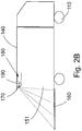
- Fig. 2A and Fig. 2B show cross-sectional views through vehicles illustrating two alternative embodiments of the present invention.
Landscapes
- Engineering & Computer Science (AREA)
- Mechanical Engineering (AREA)
- Lighting Device Outwards From Vehicle And Optical Signal (AREA)
Abstract
A method of providing a vehicle (100) with a light source (170), said vehicle (100) comprising a platform (160) located in front of an access opening (151) to a cargo space (150), which platform (160) is rotatable and moveable for loading/unloading.To provide a vehicle (100) with a reduced safety risk, the vehicle (100) comprises a light-source (170) and an air curtain (180), wherein the light source (170) is located below the ceiling (140) and in or on at least one of i) an armature (171) between the two side walls (130) and rearwards of the air curtain (180), ii) the air curtain (180), and iii) a protection bar (190) for the air curtain (180).
Description
- The present invention relates to a method of providing a vehicle with a light source, said vehicle comprising
- wheels, said wheels defining a base plane for contact with a road, the vehicle having a front and a rear defining
- a longitudinal direction parallel to said base plane, and
- a transversal direction transverse to the longitudinal direction and parallel to said base plane;
- a floor, upright walls comprising two side walls extending in the longitudinal direction, and a ceiling defining a cargo space,
- an access opening to the cargo space,
- a platform located in front of the access opening, which platform
- is rotatable about an axis parallel to the transversal direction between an upright first position and a second position substantially parallel to the base plane, and
- in the second position is moveable transverse to the base plane;
- A vehicles, such as a truck or a trailer, are typically equipped with a moveable platform for loading or unloading cargo. When it is dark, e.g. at night, the platform is not visible very well, which is a safety risk. Light from a light source in the cargo space, typically located in the ceiling of the cargo space, helps to reduce this risk.
- The object of the present invention is to provide a vehicle with a further reduced safety risk.
- To this end, a method according to the preamble is characterized in that the vehicle comprises a light-source and an air curtain, wherein the light source is located
- below the ceiling, and
- in or on at least one of i) an armature between the two side walls and rearwards of the air curtain, ii) the air curtain, and iii) a protection bar for the air curtain;
- Thus while a vehicle according to the state of the art comprising a light source in the ceiling of the cargo space may suffer from a reduced amount of light if it is equipped with an air curtain, with the method according to the invention, less light is blocked and/or more light reaches the platform, enhancing safety, in particular during loading/unloading. In the present invention, the local reduction in height of the cargo space by the presence of an air curtain is exploited to improve the illumination of the platform.
- The light source being capable of illuminating the platform means that at least part of the light will reach the platform in a horizontal position when in the second position at the same level as the floor. Typically the light source will be aimed at the platform.
- The term "located below the ceiling" includes being mounted to the ceiling (e.g by screwing an armature for the light source to the sealing). In that case, the light source is (physically) between the two upright side walls.
- If the armature is located downstream of the air curtain, then if the vehicle comprises a protection bar for the air curtain, the light source is preferably located between i) said air curtain, and ii) said protection bar for the air curtain.
- According to a favourable embodiment, the vehicle is provided with an element chosen from i) the air curtain, and ii) the protection bar for the air curtain;
wherein the element comprises at least one of a) a socket for the light source, and b) a mounted light source. - Thus it is possible to install the light source with little or no further effort and/or time, which would detract from the time the truck can be used for commercial purposes.
- According to a favourable embodiment, the light source is present inside the air curtain and with light from the light source capable of leaving the air curtain via an opening chosen from an air inlet and an air outlet.
- Thus the light source is well protected and no further openings have to be created in the air curtain.
- According to a favourable embodiment, the light source is mounted in channel of an array of channels in the outlet opening.
- This allows for easy mounting of the light source in the air curtain. It also allows for easy orientation/alignment of the light source.
- According to a favourable embodiment, the inside of the element has a reflectivity of >50%.
- This allows for a high light yield. The air curtain may be of bare aluminum metal at the inside, which satisfies this condition easily at no further cost.
- According to a favourable embodiment, the light source is electrically connected to the air curtain such that when the air curtain is powered to produce an air-curtain, light is emitted by the light source.
- Thus safety is increased because less operations have to be performed. Turning on the air curtain will automatically turn on the light. If it is desired that this does not happen in broad daylight, a daylight sensor may be included.
- An air-curtain is the flow of air produced by an air curtain.
- According to a favourable embodiment, the air curtain is an air curtain comprising a sensor for detecting when the access opening is open.
- Thus operation of the light is automatic.
- According to a favourable embodiment, the light source is electrically coupled to at least one fan for generating the air-curtain.
- Thus the light source serves a dual purpose. If it is out, which can be seen from the outside, the fan may need replacement.
- The present invention will now be illustrated with reference to the drawing where
-
Fig. 1A to Fig. 1C show cross-sectional views through vehicles illustrating three main embodiments provided using the method according to the present invention; and -
Fig. 2A andFig. 2B show cross-sectional views through vehicles illustrating two alternative embodiments. -
Fig. 1A to Fig. 1C show cross-sectional views through vehicles illustrating three embodiments of the present invention. -
Fig. 1A shows avehicle 100 comprisingwheels 110, saidwheels 110 defining a base plane for contact with a road. Thevehicle 100 has afront end 101 and arear end 102. - The
vehicle 100 also comprises afloor 120,upright walls 130 and aceiling 140 defining acargo space 150. - The
vehicle 100 comprises an access opening 151 to thecargo space 150, and aplatform 160 located in front of the access opening 151, whichplatform 160 is rotatable about a axis upright first position (not shown) and a horizontal second position (shown). In the latter orientation theplatform 160 is moveable transverse to the base plane (i.e. moveable up and down). - The
platform 160 has afirst side 161 relatively close to the axis of rotation and asecond side 162 opposite of thefirst side 161. - A
vehicle 100 as described above is generally known in the art. - Depending on the circumstances, e.g. at night, the upper surface of the platform may be sparsely illuminated, e.g. by light integrated in the
ceiling 140 of thevehicle 100. - According to the method according to the present invention, the
vehicle 100 is provided with a light-source 170. Also, thevehicle 100 comprises or is provided with anair curtain 180. Theair curtain 180 comprises anair inlet 181 and anair outlet 182. - In the main embodiment of
Fig. 1A , the light-source 170 is integrated in the air-curtain 180. - In the main embodiment of
Fig. 1B , thelight source 170 is located in aprotection bar 190 for theair curtain 180. Theprotection bar 190 extends between the longitudinal side walls of thevehicle 100, and when mounting theprotection bar 190 can be rotated about its longitudinal axis to aim thelight source 170 at theplatform 160. - In the main embodiment of
Fig. 1C anarmature 171 is mounted against theceiling 140 rearwards of theair curtain 180. -
Fig. 2A andFig. 2B show cross-sectional views through vehicles illustrating two alternative embodiments of the present invention.
Claims (8)
- A method of providing a vehicle (100) with a light source (170), said vehicle (100) comprising- wheels (110), said wheels (110) defining a base plane for contact with a road, the vehicle (100) having a front and a rear defining- a longitudinal direction parallel to said base plane, and- a transversal direction transverse to the longitudinal direction and parallel to said base plane;- a floor (120), upright walls (130) comprising two side walls extending in the longitudinal direction, and a ceiling (140) defining a cargo space (150),- an access opening (151) to the cargo space (150),- a platform (160) located in front of the access opening (151), which platform (160)said platform (160) having a first side (161) relatively close to the axis of rotation and a second side (162) opposite of the first side (161) ;- is rotatable about an axis parallel to the transversal direction between an upright first position and a second position substantially parallel to the base plane, and- in the second position is moveable transverse to the base plane;
wherein the method comprises the step of providing a light source (170) at the ceiling (140) of the vehicle (100);
characterized in that the vehicle (100) comprises a light-source (170) and an air curtain (180), wherein the light source (170) is located- below the ceiling, and- in or on at least one of i) an armature (171) between the two side walls and rearwards of the air curtain (180), ii) the air curtain (180), and iii) a protection bar (190) for the air curtain (180);said light source (170) capable of illuminating the platform (160). - The method according to claim 1, wherein the vehicle (100) is provided with an element chosen from i) the air curtain (180), and ii) the protection bar (190) for the air curtain (180);
wherein the element comprises at least one of a) a socket for the light source (170), and b) a mounted light source (170). - The method according to claim 2, wherein the light source (170) is present inside the air curtain (180) and with light from the light source (170) capable of leaving the air curtain (180) via an opening (151) chosen from an air inlet (181) and an air outlet (182).
- The method according to claim 3, wherein the light source (170) is mounted in channel of an array of channels in the outlet (182) opening (151) .
- The method according to any of the claims 2 to 4, wherein the inside of the element has a reflectivity of >50%.
- The method according to any of the preceding claims, wherein the light source (170) is electrically connected to the air curtain (180) such that when the air curtain (180) is powered to produce an air-curtain (180), light is emitted by the light source (170).
- The method according to claim 6, wherein the air curtain (180) is an air curtain (180) comprising a sensor for detecting when the access opening (151) is open.
- The method according to any of the preceding claims, wherein the light source (170) is electrically coupled to at least one fan for generating the air-curtain (180).
Applications Claiming Priority (1)
| Application Number | Priority Date | Filing Date | Title |
|---|---|---|---|
| NL2020950A NL2020950B1 (en) | 2018-05-17 | 2018-05-17 | A method of providing a vehicle with a light source |
Publications (1)
| Publication Number | Publication Date |
|---|---|
| EP3569433A1 true EP3569433A1 (en) | 2019-11-20 |
Family
ID=63145155
Family Applications (1)
| Application Number | Title | Priority Date | Filing Date |
|---|---|---|---|
| EP19174337.6A Withdrawn EP3569433A1 (en) | 2018-05-17 | 2019-05-14 | A method of providing a vehicle with a light source |
Country Status (2)
| Country | Link |
|---|---|
| EP (1) | EP3569433A1 (en) |
| NL (1) | NL2020950B1 (en) |
Citations (4)
| Publication number | Priority date | Publication date | Assignee | Title |
|---|---|---|---|---|
| JPS59118651U (en) * | 1983-01-31 | 1984-08-10 | スズキ株式会社 | Freight vehicle work light system |
| WO1985001706A1 (en) * | 1983-10-21 | 1985-04-25 | John Gundorph | Warning lamp for a truck lift |
| JP2003034178A (en) * | 2001-07-24 | 2003-02-04 | Hisanori Nakamura | Rear lighting system for vehicle |
| DE202005000304U1 (en) * | 2005-01-10 | 2005-05-04 | Lwt Luftwandtechnologie Gmbh | Refrigeration vehicle has air flow device formed by air wall device and at least one nozzle formed by core air jet nozzle with which air wall consisting of at least one core air jet and/or free jet can be blown out |
-
2018
- 2018-05-17 NL NL2020950A patent/NL2020950B1/en not_active IP Right Cessation
-
2019
- 2019-05-14 EP EP19174337.6A patent/EP3569433A1/en not_active Withdrawn
Patent Citations (4)
| Publication number | Priority date | Publication date | Assignee | Title |
|---|---|---|---|---|
| JPS59118651U (en) * | 1983-01-31 | 1984-08-10 | スズキ株式会社 | Freight vehicle work light system |
| WO1985001706A1 (en) * | 1983-10-21 | 1985-04-25 | John Gundorph | Warning lamp for a truck lift |
| JP2003034178A (en) * | 2001-07-24 | 2003-02-04 | Hisanori Nakamura | Rear lighting system for vehicle |
| DE202005000304U1 (en) * | 2005-01-10 | 2005-05-04 | Lwt Luftwandtechnologie Gmbh | Refrigeration vehicle has air flow device formed by air wall device and at least one nozzle formed by core air jet nozzle with which air wall consisting of at least one core air jet and/or free jet can be blown out |
Also Published As
| Publication number | Publication date |
|---|---|
| NL2020950B1 (en) | 2019-11-25 |
Similar Documents
| Publication | Publication Date | Title |
|---|---|---|
| JP2009007001A (en) | Headlamp control to prevent glare | |
| US10502390B1 (en) | Vehicle lamp assembly having a bezek, lens and lamp housing with a micro mesh of holes in a side wall | |
| US20110175717A1 (en) | Pulsating vehicle reverse alert light systems | |
| US10793055B1 (en) | Vehicle comprising a wind deflecting assembly and a lighting device | |
| US20050146888A1 (en) | Tailgate lighting system | |
| EP3569433A1 (en) | A method of providing a vehicle with a light source | |
| WO2014126511A1 (en) | Lighting arrangement for a commercial vehicle | |
| US12043304B2 (en) | Vehicle comprising a trailer angle determining system | |
| US11932316B2 (en) | Vehicle comprising a wind deflecting assembly and a lighting assembly | |
| WO2019150011A1 (en) | Vehicle having a device for illuminating the ground | |
| US4777569A (en) | Three-way lamp assembly for automobiles | |
| JP2009154561A (en) | Loading platform and transport vehicle having the same loading platform | |
| KR101489771B1 (en) | Head lamp for vehicles | |
| FR2702544A1 (en) | Optical group for raised brake light for motor vehicles. | |
| JP3449477B2 (en) | Vehicle lamp | |
| EP0981455B1 (en) | Lighting fixture | |
| KR200462560Y1 (en) | Sidelamp for a car | |
| US20060279861A1 (en) | Saftey mirror | |
| KR100449291B1 (en) | Structure for securiting a night viewer of vehicle | |
| KR20070083816A (en) | Rearview mirror for vehicle reverse | |
| KR200249159Y1 (en) | Wing Body Truck with Side lamp | |
| US10035448B1 (en) | Pivoting strobe light | |
| FR3157303A1 (en) | Motor vehicle grille comprising an illuminated central logo and device for controlling such a logo | |
| US20060087857A1 (en) | Extra rear-view mirror for a vehicle | |
| CN116164252A (en) | Vehicle side auxiliary lighting lamp and working method |
Legal Events
| Date | Code | Title | Description |
|---|---|---|---|
| PUAI | Public reference made under article 153(3) epc to a published international application that has entered the european phase |
Free format text: ORIGINAL CODE: 0009012 |
|
| AK | Designated contracting states |
Kind code of ref document: A1 Designated state(s): AL AT BE BG CH CY CZ DE DK EE ES FI FR GB GR HR HU IE IS IT LI LT LU LV MC MK MT NL NO PL PT RO RS SE SI SK SM TR |
|
| AX | Request for extension of the european patent |
Extension state: BA ME |
|
| STAA | Information on the status of an ep patent application or granted ep patent |
Free format text: STATUS: THE APPLICATION IS DEEMED TO BE WITHDRAWN |
|
| 18D | Application deemed to be withdrawn |
Effective date: 20200603 |