EP3569340A1 - Arc start control method for forward and reverse feeding arc welding - Google Patents
Arc start control method for forward and reverse feeding arc welding Download PDFInfo
- Publication number
- EP3569340A1 EP3569340A1 EP17890890.1A EP17890890A EP3569340A1 EP 3569340 A1 EP3569340 A1 EP 3569340A1 EP 17890890 A EP17890890 A EP 17890890A EP 3569340 A1 EP3569340 A1 EP 3569340A1
- Authority
- EP
- European Patent Office
- Prior art keywords
- period
- feed
- welding
- arc
- pulse
- Prior art date
- Legal status (The legal status is an assumption and is not a legal conclusion. Google has not performed a legal analysis and makes no representation as to the accuracy of the status listed.)
- Granted
Links
Images

Classifications
-
- B—PERFORMING OPERATIONS; TRANSPORTING
- B23—MACHINE TOOLS; METAL-WORKING NOT OTHERWISE PROVIDED FOR
- B23K—SOLDERING OR UNSOLDERING; WELDING; CLADDING OR PLATING BY SOLDERING OR WELDING; CUTTING BY APPLYING HEAT LOCALLY, e.g. FLAME CUTTING; WORKING BY LASER BEAM
- B23K9/00—Arc welding or cutting
- B23K9/06—Arrangements or circuits for starting the arc, e.g. by generating ignition voltage, or for stabilising the arc
- B23K9/067—Starting the arc
-
- B—PERFORMING OPERATIONS; TRANSPORTING
- B23—MACHINE TOOLS; METAL-WORKING NOT OTHERWISE PROVIDED FOR
- B23K—SOLDERING OR UNSOLDERING; WELDING; CLADDING OR PLATING BY SOLDERING OR WELDING; CUTTING BY APPLYING HEAT LOCALLY, e.g. FLAME CUTTING; WORKING BY LASER BEAM
- B23K9/00—Arc welding or cutting
- B23K9/09—Arrangements or circuits for arc welding with pulsed current or voltage
-
- B—PERFORMING OPERATIONS; TRANSPORTING
- B23—MACHINE TOOLS; METAL-WORKING NOT OTHERWISE PROVIDED FOR
- B23K—SOLDERING OR UNSOLDERING; WELDING; CLADDING OR PLATING BY SOLDERING OR WELDING; CUTTING BY APPLYING HEAT LOCALLY, e.g. FLAME CUTTING; WORKING BY LASER BEAM
- B23K9/00—Arc welding or cutting
- B23K9/12—Automatic feeding or moving of electrodes or work for spot or seam welding or cutting
-
- B—PERFORMING OPERATIONS; TRANSPORTING
- B23—MACHINE TOOLS; METAL-WORKING NOT OTHERWISE PROVIDED FOR
- B23K—SOLDERING OR UNSOLDERING; WELDING; CLADDING OR PLATING BY SOLDERING OR WELDING; CUTTING BY APPLYING HEAT LOCALLY, e.g. FLAME CUTTING; WORKING BY LASER BEAM
- B23K9/00—Arc welding or cutting
- B23K9/12—Automatic feeding or moving of electrodes or work for spot or seam welding or cutting
- B23K9/124—Circuits or methods for feeding welding wire
- B23K9/125—Feeding of electrodes
-
- B—PERFORMING OPERATIONS; TRANSPORTING
- B23—MACHINE TOOLS; METAL-WORKING NOT OTHERWISE PROVIDED FOR
- B23K—SOLDERING OR UNSOLDERING; WELDING; CLADDING OR PLATING BY SOLDERING OR WELDING; CUTTING BY APPLYING HEAT LOCALLY, e.g. FLAME CUTTING; WORKING BY LASER BEAM
- B23K9/00—Arc welding or cutting
- B23K9/06—Arrangements or circuits for starting the arc, e.g. by generating ignition voltage, or for stabilising the arc
- B23K9/073—Stabilising the arc
Definitions
- the present invention relates to an arc start control method for forward and reverse feed arc welding in which forward and reverse feed control of alternately switching a feed speed of a welding wire between a forward feed period and a reverse feed period is performed to generate a short circuit period and an arc period to perform welding.
- the welding is performed by feeding a welding wire as a consumable electrode at a constant speed, and generating an arc between the welding wire and a base material.
- a welding state of alternately repeating the welding wire and the base material in a short circuit period and an arc period is often obtained.
- the welding wire is fed forward, the welding wire is brought into contact with the base material and the welding current is energized, and then the welding is started by performing forward and reverse feed control from the reverse feed period of welding wire (see, for example, Patent Literature 1).
- Patent Literature 1 WO 2016/039113
- an object of the present invention is to provide an arc start control method for forward and reverse feed arc welding, which is capable of improving the quality of the weld bead at the welding start portion in the forward and reverse feed arc welding control method.
- an arc start control method for forward and reverse feed arc welding of the present disclosure is characterized in that:
- the welding wire is fed forward during the pulse period.
- the pulse period is set to a predetermined period or a period in which the pulse current has a predetermined number of cycles.
- a speed of the forward feed is set so that the arc period is continuous during the pulse period.
- the speed of the forward feed is changed based on a time length of the pulse period and/or a welding voltage value during the pulse period.
- a pull-side feed motor which performs the forward and reverse feed control and a push-side feed motor which performs forward feed control are included, and an acceleration period of the pull-side feed motor is shorter than an acceleration period of the push-side feed motor at the start of the pulse period.
- the acceleration period of the push-side feed motor at the start of the pulse period is set to a period longer than the pulse period.
- the quality of the weld bead at the welding start portion can be improved in the forward and reverse feed arc welding control method.
- Fig. 1 is a block diagram of a welding power source for performing an arc start control method for forward and reverse feed arc welding according to a first embodiment of the present invention. Hereinafter, each block will be described below with reference to Fig. 1 .
- a power source main circuit PM receives an output from a 3-phase 200 V commercial power source (not shown) or the like, performs output control by inverter control according to a drive signal Dv to be described later, and outputs an output voltage E.
- the power source main circuit PM includes a primary rectifier for rectifying the commercial power source, a smoothing capacitor for smoothing a rectified direct current, an inverter circuit driven by the drive signal Dv and converting the smoothed direct current into a high-frequency alternating current, a high-frequency transformer for stepping down the high-frequency alternating current to a voltage value suitable for welding, and a secondary rectifier for rectifying the step-down high-frequency alternating current into a direct current, which are not shown.
- a reactor WL smoothes the output voltage E.
- the inductance value of the reactor WL is, for example, 100 ⁇ H.
- a feed motor WM receives a feed control signal Fc to be described later as an input and alternately switches forward feed and reverse feed to feed a welding wire 1 at a feed speed Fw.
- a motor with fast transient response is used as the feed motor WM.
- the feed motor WM may be provided near a tip of a welding torch 4.
- the welding wire 1 is fed inside the welding torch 4 by the rotation of a feed roll 5 coupled to the feed motor WM, and an arc 3 is generated between the welding wire 1 and a base material 2.
- a welding voltage Vw is applied between a power source tip (not shown) in the welding torch 4 and the base material 2, and thus a welding current Iw is energized.
- An output voltage setting circuit ER outputs a predetermined output voltage setting signal Er.
- An output voltage detection circuit ED detects and smoothes the output voltage E and outputs an output voltage detection signal Ed.
- a voltage error amplification circuit EV receives the output voltage setting signal Er and the output voltage detection signal Ed as inputs, amplifies an error between the output voltage setting signal Er(+) and the output voltage detection signal Ed(-), and outputs a voltage error amplification signal Ev. With this circuit, the welding power source is subjected to constant voltage control.
- a current detection circuit ID detects the welding current Iw and outputs a current detection signal Id.
- a current energization determination circuit CD receives the current detection signal Id as an input, determines that the welding current Iw is energized when the value of the current detection signal Id is equal to or larger than a threshold value (about 10 A), and outputs a current energization determination signal Cd which is at a high level.
- a pulse current setting circuit IPR receives the current energization determination signal Cd as an input, takes a predetermined peak current value during a predetermined peak period, then takes a predetermined base current value during a predetermined base period, and thereafter repeats the peak period and the base period when the current energization determination signal Cd changes to be in a high level, and outputs a pulse current setting signal Ipr.
- a current error amplification circuit EI receives the pulse current setting signal Ipr and the current detection signal Id as inputs, amplifies an error between the pulse current setting signal Ipr(+) and the current detection signal Id(-), and outputs a current error amplification signal Ei. With this circuit, the welding power source is subjected to constant current control during the pulse period.
- a pulse period setting circuit TPR outputs a predetermined pulse period setting signal Tpr.
- the pulse period setting signal Tpr may be set to a predetermined period, or may be set to a period in which the pulse current has a predetermined number of cycles.
- a pulse period timer circuit STP receives the current energization determination signal Cd and the pulse period setting signal Tpr as inputs, and outputs a pulse period timer signal Stp which is in a high level during a pulse period Tp determined by the pulse period setting signal Tpr from the time when the current energization determination signal Cd changes to be at a high level (energization).
- a power source characteristic switching circuit SW receives the current error amplification signal Ei, the voltage error amplification signal Ev and the pulse period timer signal Stp as inputs, outputs the current error amplification signal Ei as an error amplification signal Ea during the pulse period Tp when the pulse period timer signal Stp is at a high level, and outputs the voltage error amplification signal Ev as an error amplification signal Ea during a steady welding period when the pulse period timer signal Stp is at a low level.
- the welding power source is subjected to constant current control during the pulse period Tp, and is subjected to constant voltage control during the steady welding period.
- a voltage detection circuit VD detects the welding voltage Vw and outputs a voltage detection signal Vd.
- a short circuit determination circuit SD receives the voltage detection signal Vd as an input, and outputs a short circuit determination signal Sd which is determined to be at a short circuit period and at a high level when the value of the voltage detection signal Vd is less than a short circuit determination value (about 10 V), and is determined to be at an arc period and at a low level when the value of the voltage detection signal Vd is equal to or larger than the short circuit determination value.
- a welding start circuit ST outputs a welding start signal St which is at a high level when the welding power source is started.
- the welding start circuit ST corresponds to a start switch of the welding torch 4, a programmable logic controller for controlling a welding process, a robot control device, or the like.
- a drive circuit DV receives the error amplification signal Ea and the welding start signal St as inputs, performs PWM modulation control based on the error amplification signal Ea when the welding start signal St is at a high level (welding start), and outputs the drive signal Dv for driving the inverter circuit in the power source main circuit PM.
- a pulse period forward feed speed setting circuit FPR receives the pulse period setting signal Tpr and the voltage detection signal Vd as inputs, and outputs a pulse period forward feed speed setting signal Fpr calculated based on a predetermined function to which both the abvoe values are input.
- This function is set, for example, as follows.
- the initial value of Fpr is set according to the value of the pulse period setting signal Tpr.
- the initial value is corrected based on the average value (smooth value) of the voltage detection signal Vd during the pulse period Tp.
- the larger the value of the pulse period setting signal Tpr (the longer the pulse period Tp), the larger the initial value.
- the larger the average value of the voltage detection signal Vd the larger the value of Fpr.
- the value of Fpr may be changed according to either the pulse period setting signal Tpr or the voltage detection signal Vd.
- a forward feed peak value setting circuit FSR outputs a predetermined forward feed peak value setting signal Fsr.
- a reverse feed peak value setting circuit FRR outputs a predetermined reverse feed peak value setting signal Frr.
- a feed speed setting circuit FR receives the pulse period forward feed speed setting signal Fpr, the forward feed peak value setting signal Fsr, the reverse feed peak value setting signal Frr, the pulse period timer signal Stp and the short circuit determination signal Sd as inputs, performs the process to be described later with reference to Fig. 2 and outputs a feed speed setting signal Fr.
- a feed control circuit FC receives the feed speed setting signal Fr as an input and outputs a feed control signal Fc for feeding the welding wire 1 at a feed speed Fw equivalent to the value of the feed speed setting signal Fr to the feed motor WM.
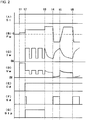
- Fig. 2 is a timing chart of each signal in the welding power source of Fig. 1 showing the arc start control method for forward and reverse feed arc welding according to the first embodiment of the present invention.
- (A) shows the change of the welding start signal St with time
- (B) shows the change of the feed speed Fw with time
- (C) shows the change of the welding current Iw with time
- (D) shows the change of the welding voltage Vw with time
- E) shows the change of the current energization determination signal Cd with time
- (F) shows the change of the short circuit determination signal Sd with time
- G shows the change of the pulse period timer signal Stp with time.
- the operation of each signal at arc start will be described below with reference to Fig. 2 .
- (B) of Fig. 2 it is a forward feed period when the feed speed Fw is above 0, and it is a reverse feed period when the feed speed Fw is below 0.
- the forward feed is to feed the welding wire 1 in a direction close to the base material 2, and the reverse feeding is to feed the welding wire 1 in a direction away from the base material 2.
- the feed speed Fw changes from 0 to a predetermined positive slow-down speed, and the welding wire 1 is fed forward, as shown in (B) of Fig. 2 .
- the slow-down speed is set to a small value of about 1 m/min to 2 m/min.
- the welding voltage Vw becomes a no-load voltage value of the maximum output voltage value, as shown in (D) of Fig. 2 .
- the welding current Iw is 0 A because it is not energized.
- the welding current Iw is energized to generate the arc 3.
- the short circuit determination signal Sd changes into a high level (short circuit) as shown in (F) of Fig. 2 .
- the arc 3 is generated, so that the short circuit determination signal Sd changes into a low level.
- the welding current Iw starts to be energized as shown in (C) of Fig. 2 , and the current energization determination signal Cd changes into a high level (energization) as shown in (E) of Fig. 2 .
- the pulse period timer signal Stp changes into a high level, and then maintains at the high level during the pulse period Tp from the time points t2 to t3 determined by the pulse period setting signal Tpr.
- the pulse current determined by the pulse current setting signal Ipr is energized.
- the pulse current has a waveform which repeats a predetermined peak period having a predetermined peak current value and a predetermined base period having a predetermined base current value as one cycle.
- the welding voltage Vw has a pulse waveform proportional to the arc length.
- the pulse period Tp is set to a predetermined period or a period in which the pulse current has a predetermined number of cycles.
- Waveform parameters (peak current value, peak period, base current value, base period) of the pulse current and pulse period Tp are set to values at which the toe portion of the weld bead at the welding start portion is well matched and has a flat shape.
- peak current value 350 A
- peak period 1.5 ms
- base current value 50 A
- base period 1.5 ms
- pulse period Tp 10 ms to 50 ms.
- the feed speed Fw is a forward feed speed Fp determined by the pulse period forward feed speed setting signal Fpr.
- the forward feed speed Fp is set so that the arc period is continuous during the pulse period.
- the forward feed speed Fp is set to be 10 m/min.
- the forward feed speed Fp may be changed based on the time length and/or the welding voltage Vw during the pulse period Tp. This is because the arc length becomes longer as the pulse period Tp becomes longer, so that the forward feed speed Fp is increased to prevent the arc length from being longer. Since the average value of the welding voltage Vw is proportional to the arc length, the arc length is detected according to the welding voltage Vw, and when the arc length becomes longer, the forward feed speed Fp is increased to prevent the arc length from being longer. When the arc length becomes longer, the shield state is insufficient and the arc state is unstable. Further, when the arc length becomes longer, a large amount of smut (soot) is generated and the bead appearance is worse.
- the pulse period Tp ends and the steady welding period starts.
- the steady welding period starts from the forward feed period, and the forward feed period ends when a short circuit is generated at a time point t4.
- the welding wire is fed forward at a predetermined forward feed speed.
- the forward feed speed is set independently of the forward feed speed Fp in the pulse period Tp and a forward feed peak value Fs to described later, and is set to a value same as or a different from the above two values.
- the welding voltage Vw sharply decreases to a short circuit voltage value of approximately 0 V as shown in (D) of Fig. 2 , so that the short circuit determination signal Sd changes into a high level as shown in (F) of Fig. 2 .
- the feed speed Fw changes with a slope from the forward feed speed to a reverse feed peak value Frp determined by the reverse feed peak value setting signal Frr.
- the reverse feed period continues until the arc 3 is regenerated at a time point t5.
- the welding current Iw gradually increases, and as shown in (D) of Fig. 2 , the welding voltage Vw remains at the short circuit voltage value.
- the welding current Iw gradually decreases, and as shown in (D) of Fig. 2 , the welding voltage Vw becomes an arc voltage value.
- the feed speed Fw during the steady welding period has a waveform which changes into substantially trapezoidal shape having positive or negative values, and the average value thereof is a positive value. Therefore, the welding wire 1 is fed forward on average.
- the pulse period during which a pulse current is energized for a plurality of number of times is provided, and thereafter the forward and reverse feed control is started from the forward feed period of the welding wire.
- the heat input to the base material can be increased by energizing the pulse current at the arc start.
- the bead at the welding start portion can be made into a flat shape, and the match of the toe portion can be improved.
- the switching from the pulse period to the forward and reverse feed control is started from the forward feed period. Accordingly, the welding state can be switched smoothly without being unstable.
- the welding wire is fed forward during the pulse period. Accordingly, the welding state can be stabilized during the pulse period.
- the pulse period is set to a predetermined period or a period in which the pulse current has a predetermined number of cycles. Accordingly, the heat input to the welding start portion can be set to an appropriate value. As a result, the bead at the welding start portion and the bead at a steady welding portion can be made into a substantially identical shape, and the welding quality can be improved.
- the forward feed speed of the welding wire is set so that the arc period is continuous during the pulse period. Accordingly, since almost no short circuit is generated during the pulse period, the heat input to the base material during the pulse period can be accurately controlled. As a result, the variation in the bead shape of the welding start portion can be prevented.
- the forward feed speed is changed based on the time length of the pulse period and/or the welding voltage value during the pulse period.
- the arc length becomes longer as the pulse period becomes longer. Therefore, as the time length of the pulse period becomes longer, the arc length can be maintained at an appropriate value by increasing the forward feed speed.
- the arc length can be detected according to the welding voltage, the arc length can be maintained at an appropriate value by changing the forward feed speed according to the welding voltage. As a result, the welding state can be prevented from being unstable during the pulse period.
- the invention of the second embodiment includes a push-side feed motor which performs forward feed control in addition to the pull-side feed motor which performs the forward and reverse feed control of the first embodiment.
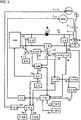
- Fig. 3 is a block diagram of a welding power source for performing an arc start control method for forward and reverse feed arc welding according to the second embodiment of the present invention.
- Fig. 3 corresponds to Fig. 1 described above, in which the same reference numerals are attached to the same blocks, and description thereof will not be repeated.
- a push-side feed motor WM2 a steady feed speed setting circuit FCR, an acceleration period setting circuit TUR, a second feed speed setting circuit FR2 and a second feed control circuit FC2 are added to the configuration in Fig. 1 .
- the blocks will be described below with reference to Fig. 3 .
- the feed motor WM shown in Fig. 1 serves as a pull-side feed motor in Fig. 3 and is provided on a downstream side of the feed system.
- the forward and reverse feed control for the pull-side feed motor WM is the same as that of the first embodiment.
- the push-side feed motor WM2 is newly provided on the upstream side of the feed system.
- the push-side feed motor WM2 is subjected to forward feed control with a second feed control signal Fc2 to be described later.
- the steady feed speed setting circuit FCR outputs a predetermined steady feed speed setting signal Fcr.
- the value of the steady feed speed setting signal Fcr is set to a value substantially same as the average value of the feed speed setting signal Fr to the pull-side feed motor WM during the steady welding period.
- An acceleration period setting circuit TUR outputs a predetermined acceleration period setting signal Tur.
- the value of the acceleration period setting signal Tur is set to a value larger than the value of the pulse period setting signal Tpr. That is, pulse period Tp ⁇ acceleration period Tu.
- the second feed speed setting circuit FR2 receives the welding start signal St, the pulse period timer signal Stp, the acceleration period setting signal Tur, and the steady feed speed setting signal Fcr as inputs, performs the process to be described later with reference to Fig. 4 , and outputs a second feed speed setting signal Fr2.
- the second feed control circuit FC2 receives the second feed speed setting signal Fr2 as an input, and outputs, to the push-side feed motor WM2, a second feed control signal Fc2 for rotating the push-side feed motor WM2 at a feed speed corresponding to the value of the second feed speed setting signal Fr2.
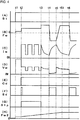
- Fig. 4 is a timing chart of each signal in the welding power source of Fig. 3 showing the arc start control method for forward and reverse feed arc welding according to the second embodiment of the present invention.
- (A) shows the change of the welding start signal St with time
- (B) shows the change of the pull-side feed speed Fw with time
- (C) shows the change of the welding current Iw with time
- (D) shows the change of the welding voltage Vw with time
- E) shows the change of the current energization determination signal Cd with time
- (F) shows the change of the short circuit determination signal Sd with time
- G shows the change of the pulse period timer signal Stp with time
- (H) shows the change of a push-side feed speed Fw2 with time.
- Fig. 4 corresponds to Fig. 2 described above, and is obtained by adding the push-side feed speed Fw2 shown in (H) of Fig. 4 to Fig. 2 .
- the operation of each signal other than the push-side feed speed Fw2 is the same as that of Fig. 2 , so that the description will not be repeated.
- the operation of the push-side feed speed Fw2 at the start of welding will be described with reference to Fig. 4 .
- the pull-side feed speed Fw changes from 0 to a predetermined positive slow-down speed as shown in (B) of Fig. 4
- the push-side feed speed Fw2 changes from 0 to a predetermined positive second slow-down speed as shown in (H) of Fig. 4
- the welding wire is fed forward at a low speed.
- the slow-down speed and the second slow-down speed are set to substantially the same value.
- the current energization determination signal Cd changes into a high level as shown in (E) of Fig. 4 .
- the pull-side feed speed Fw is rapidly accelerated to a predetermined forward feed speed Fp as shown in (B) of Fig. 4 .
- the push-side feed speed Fw2 is gradually accelerated and converges to a steady feed speed determined by the steady feed speed setting signal Fcr at a time point t51 between the time points t5 and t6.
- the acceleration period of the pull-side feed speed Fw is set to a time shorter than the acceleration period Tu of the push-side feed speed Fw2.
- the acceleration period of the pull-side feed speed Fw is set to about 0.5 ms to 5 ms.
- the acceleration period Tu of the push-side feed speed Fw2 is set to about 20 ms to 100 ms by the acceleration period setting signal Tur. In this way, the transition to a state where the arc length becomes an appropriate value after the arc is generated at the time point t2 is made smoother. Thus, spattering at the arc start can be reduced.
- the acceleration period Tu of the push-side feed speed Fw2 is preferably set to a period longer than the pulse period Tp. In this way, the transition from the pulse period Tp to the steady welding period is made smoother, and the welding quality is further improved.
- the pull-side feed motor which performs the forward and reverse feed control and the push-side feed motor which performs forward feed control are included, and the acceleration period of the pull-side feed motor at the start of the pulse period is set to a period shorter than the acceleration period of the push-side feed motor. Accordingly, in the second embodiment, in addition to the effects of the first embodiment, the spattering at the arc start can be further reduced.
- the acceleration period of the push-side feed motor at the start of the pulse period is set to a period longer than the pulse period. Accordingly, in the second embodiment, the transition from the pulse period to the steady welding period can be made smoother.
- the quality of the weld bead at the welding start portion can be improved in the forward and reverse feed arc welding control method.
Landscapes
- Engineering & Computer Science (AREA)
- Physics & Mathematics (AREA)
- Plasma & Fusion (AREA)
- Mechanical Engineering (AREA)
- Arc Welding Control (AREA)
Abstract
Description
- The present invention relates to an arc start control method for forward and reverse feed arc welding in which forward and reverse feed control of alternately switching a feed speed of a welding wire between a forward feed period and a reverse feed period is performed to generate a short circuit period and an arc period to perform welding.
- In general consumable electrode-type arc welding, the welding is performed by feeding a welding wire as a consumable electrode at a constant speed, and generating an arc between the welding wire and a base material. In the consumable electrode-type arc welding, a welding state of alternately repeating the welding wire and the base material in a short circuit period and an arc period is often obtained.
- In order to further improve the welding quality, it is common practice to perform welding by performing forward and reverse feed control in which the feed speed of the welding wire is switched alternately between a forward feed period and a reverse feed period.
- In the forward and reverse feed arc welding control method, at arc start, the welding wire is fed forward, the welding wire is brought into contact with the base material and the welding current is energized, and then the welding is started by performing forward and reverse feed control from the reverse feed period of welding wire (see, for example, Patent Literature 1).
- Patent Literature 1:
WO 2016/039113 - In the forward and reverse feed arc welding control method, stable welding can be performed during a steady welding period. However, in the forward and reverse feed arc welding control method, there is a problem that the bead appearance at a welding start portion is inferior to that of usual arc welding method in which only the forward feed is performed. This tends to cause the bead appearance at the start of welding to be convex, and the match between the bead and the base material at a toe portion to deteriorate. When the material of the base material is an aluminum material, this problem is significant.
- Therefore, an object of the present invention is to provide an arc start control method for forward and reverse feed arc welding, which is capable of improving the quality of the weld bead at the welding start portion in the forward and reverse feed arc welding control method.
- In order to solve the above object, an arc start control method for forward and reverse feed arc welding of the present disclosure is characterized in that:
- an arc start control method for forward and reverse feed arc welding in which forward and reverse feed control of alternately switching a feed speed of a welding wire between a forward feed period and a reverse feed period is performed to generate a short circuit period and an arc period to perform welding,
- wherein at arc start, a pulse period during which a pulse current is energized for a plurality of number of times is provided, and thereafter the forward and reverse feed control is started from the forward feed period of the welding wire.
- In the arc start control method for forward and reverse feed arc welding according to the present disclosure, the welding wire is fed forward during the pulse period.
- In the arc start control method for forward and reverse feed arc welding according to the present disclosure, the pulse period is set to a predetermined period or a period in which the pulse current has a predetermined number of cycles.
- In the arc start control method for forward and reverse feed arc welding according to the present disclosure, a speed of the forward feed is set so that the arc period is continuous during the pulse period.
- In the arc start control method for forward and reverse feed arc welding according to the present disclosure, the speed of the forward feed is changed based on a time length of the pulse period and/or a welding voltage value during the pulse period.
- In the arc start control method for forward and reverse feed arc welding according to the present disclosure, during the pulse period, a pull-side feed motor which performs the forward and reverse feed control and a push-side feed motor which performs forward feed control are included, and
an acceleration period of the pull-side feed motor is shorter than an acceleration period of the push-side feed motor at the start of the pulse period. - In the arc start control method for forward and reverse feed arc welding according to the present disclosure, the acceleration period of the push-side feed motor at the start of the pulse period is set to a period longer than the pulse period.
- According to the present invention, the quality of the weld bead at the welding start portion can be improved in the forward and reverse feed arc welding control method.
-
-
Fig. 1 is a block diagram of a welding power source for performing an arc start control method for forward and reverse feed arc welding according to a first embodiment of the present invention. -
Fig. 2 is a timing chart of each signal in the welding power source ofFig. 1 showing the arc start control method for forward and reverse feed arc welding according to the first embodiment of the present invention. -
Fig. 3 is a block diagram of a welding power source for performing an arc start control method for forward and reverse feed arc welding according to a second embodiment of the present invention. -
Fig. 4 is a timing chart of each signal in the welding power source ofFig. 3 showing the arc start control method for forward and reverse feed arc welding according to the second embodiment of the present invention. - Hereinafter, embodiments of the present invention will be described with reference to the drawings.
-
Fig. 1 is a block diagram of a welding power source for performing an arc start control method for forward and reverse feed arc welding according to a first embodiment of the present invention. Hereinafter, each block will be described below with reference toFig. 1 . - A power source main circuit PM receives an output from a 3-phase 200 V commercial power source (not shown) or the like, performs output control by inverter control according to a drive signal Dv to be described later, and outputs an output voltage E. The power source main circuit PM includes a primary rectifier for rectifying the commercial power source, a smoothing capacitor for smoothing a rectified direct current, an inverter circuit driven by the drive signal Dv and converting the smoothed direct current into a high-frequency alternating current, a high-frequency transformer for stepping down the high-frequency alternating current to a voltage value suitable for welding, and a secondary rectifier for rectifying the step-down high-frequency alternating current into a direct current, which are not shown.
- A reactor WL smoothes the output voltage E. The inductance value of the reactor WL is, for example, 100 µH.
- A feed motor WM receives a feed control signal Fc to be described later as an input and alternately switches forward feed and reverse feed to feed a
welding wire 1 at a feed speed Fw. A motor with fast transient response is used as the feed motor WM. In order to increase the change rate of the feed speed Fw of thewelding wire 1 and speed up the reversal of the feed direction, the feed motor WM may be provided near a tip of a welding torch 4. - The
welding wire 1 is fed inside the welding torch 4 by the rotation of afeed roll 5 coupled to the feed motor WM, and anarc 3 is generated between thewelding wire 1 and abase material 2. A welding voltage Vw is applied between a power source tip (not shown) in the welding torch 4 and thebase material 2, and thus a welding current Iw is energized. - An output voltage setting circuit ER outputs a predetermined output voltage setting signal Er. An output voltage detection circuit ED detects and smoothes the output voltage E and outputs an output voltage detection signal Ed.
- A voltage error amplification circuit EV receives the output voltage setting signal Er and the output voltage detection signal Ed as inputs, amplifies an error between the output voltage setting signal Er(+) and the output voltage detection signal Ed(-), and outputs a voltage error amplification signal Ev. With this circuit, the welding power source is subjected to constant voltage control.
- A current detection circuit ID detects the welding current Iw and outputs a current detection signal Id.
- A current energization determination circuit CD receives the current detection signal Id as an input, determines that the welding current Iw is energized when the value of the current detection signal Id is equal to or larger than a threshold value (about 10 A), and outputs a current energization determination signal Cd which is at a high level.
- A pulse current setting circuit IPR receives the current energization determination signal Cd as an input, takes a predetermined peak current value during a predetermined peak period, then takes a predetermined base current value during a predetermined base period, and thereafter repeats the peak period and the base period when the current energization determination signal Cd changes to be in a high level, and outputs a pulse current setting signal Ipr.
- A current error amplification circuit EI receives the pulse current setting signal Ipr and the current detection signal Id as inputs, amplifies an error between the pulse current setting signal Ipr(+) and the current detection signal Id(-), and outputs a current error amplification signal Ei. With this circuit, the welding power source is subjected to constant current control during the pulse period.
- A pulse period setting circuit TPR outputs a predetermined pulse period setting signal Tpr. The pulse period setting signal Tpr may be set to a predetermined period, or may be set to a period in which the pulse current has a predetermined number of cycles.
- A pulse period timer circuit STP receives the current energization determination signal Cd and the pulse period setting signal Tpr as inputs, and outputs a pulse period timer signal Stp which is in a high level during a pulse period Tp determined by the pulse period setting signal Tpr from the time when the current energization determination signal Cd changes to be at a high level (energization).
- A power source characteristic switching circuit SW receives the current error amplification signal Ei, the voltage error amplification signal Ev and the pulse period timer signal Stp as inputs, outputs the current error amplification signal Ei as an error amplification signal Ea during the pulse period Tp when the pulse period timer signal Stp is at a high level, and outputs the voltage error amplification signal Ev as an error amplification signal Ea during a steady welding period when the pulse period timer signal Stp is at a low level. With this circuit, the welding power source is subjected to constant current control during the pulse period Tp, and is subjected to constant voltage control during the steady welding period.
- A voltage detection circuit VD detects the welding voltage Vw and outputs a voltage detection signal Vd. A short circuit determination circuit SD receives the voltage detection signal Vd as an input, and outputs a short circuit determination signal Sd which is determined to be at a short circuit period and at a high level when the value of the voltage detection signal Vd is less than a short circuit determination value (about 10 V), and is determined to be at an arc period and at a low level when the value of the voltage detection signal Vd is equal to or larger than the short circuit determination value.
- A welding start circuit ST outputs a welding start signal St which is at a high level when the welding power source is started. The welding start circuit ST corresponds to a start switch of the welding torch 4, a programmable logic controller for controlling a welding process, a robot control device, or the like.
- A drive circuit DV receives the error amplification signal Ea and the welding start signal St as inputs, performs PWM modulation control based on the error amplification signal Ea when the welding start signal St is at a high level (welding start), and outputs the drive signal Dv for driving the inverter circuit in the power source main circuit PM.
- A pulse period forward feed speed setting circuit FPR receives the pulse period setting signal Tpr and the voltage detection signal Vd as inputs, and outputs a pulse period forward feed speed setting signal Fpr calculated based on a predetermined function to which both the abvoe values are input. This function is set, for example, as follows. The initial value of Fpr is set according to the value of the pulse period setting signal Tpr. Then, the initial value is corrected based on the average value (smooth value) of the voltage detection signal Vd during the pulse period Tp. The larger the value of the pulse period setting signal Tpr (the longer the pulse period Tp), the larger the initial value. In addition, the larger the average value of the voltage detection signal Vd, the larger the value of Fpr. The value of Fpr may be changed according to either the pulse period setting signal Tpr or the voltage detection signal Vd.
- A forward feed peak value setting circuit FSR outputs a predetermined forward feed peak value setting signal Fsr. A reverse feed peak value setting circuit FRR outputs a predetermined reverse feed peak value setting signal Frr.
- A feed speed setting circuit FR receives the pulse period forward feed speed setting signal Fpr, the forward feed peak value setting signal Fsr, the reverse feed peak value setting signal Frr, the pulse period timer signal Stp and the short circuit determination signal Sd as inputs, performs the process to be described later with reference to
Fig. 2 and outputs a feed speed setting signal Fr. - A feed control circuit FC receives the feed speed setting signal Fr as an input and outputs a feed control signal Fc for feeding the
welding wire 1 at a feed speed Fw equivalent to the value of the feed speed setting signal Fr to the feed motor WM. -
Fig. 2 is a timing chart of each signal in the welding power source ofFig. 1 showing the arc start control method for forward and reverse feed arc welding according to the first embodiment of the present invention. InFig. 2 , (A) shows the change of the welding start signal St with time, (B) shows the change of the feed speed Fw with time, (C) shows the change of the welding current Iw with time, (D) shows the change of the welding voltage Vw with time, (E) shows the change of the current energization determination signal Cd with time, (F) shows the change of the short circuit determination signal Sd with time, and (G) shows the change of the pulse period timer signal Stp with time. The operation of each signal at arc start will be described below with reference toFig. 2 . - As shown in (B) of
Fig. 2 , it is a forward feed period when the feed speed Fw is above 0, and it is a reverse feed period when the feed speed Fw is below 0. The forward feed is to feed thewelding wire 1 in a direction close to thebase material 2, and the reverse feeding is to feed thewelding wire 1 in a direction away from thebase material 2. - As shown in (A) of
Fig. 2 , at a time point t1, when the welding start signal St changes to be at a high level (welding start), the feed speed Fw changes from 0 to a predetermined positive slow-down speed, and thewelding wire 1 is fed forward, as shown in (B) ofFig. 2 . The slow-down speed is set to a small value of about 1 m/min to 2 m/min. At the same time, at the time point t1, since the welding power source is started, the welding voltage Vw becomes a no-load voltage value of the maximum output voltage value, as shown in (D) ofFig. 2 . As shown in (C) ofFig. 2 , the welding current Iw is 0 A because it is not energized. - At a time point t2, when the
welding wire 1 is brought into contact with thebase material 2 due to the above forward feed, the welding current Iw is energized to generate thearc 3. As shown in (D) ofFig. 2 , since the welding voltage Vw sharply decreases to a short circuit voltage value of several volts, and the value of the welding voltage Vw is less than a predetermined short circuit determination value (about 10 V), the short circuit determination signal Sd changes into a high level (short circuit) as shown in (F) ofFig. 2 . Immediately after the short circuit is released, thearc 3 is generated, so that the short circuit determination signal Sd changes into a low level. At the same time, at the time point t2, the welding current Iw starts to be energized as shown in (C) ofFig. 2 , and the current energization determination signal Cd changes into a high level (energization) as shown in (E) ofFig. 2 . In response to this, as shown in (G) ofFig. 2 , the pulse period timer signal Stp changes into a high level, and then maintains at the high level during the pulse period Tp from the time points t2 to t3 determined by the pulse period setting signal Tpr. - As shown in (C) of
Fig. 2 , during the pulse period Tp, the pulse current determined by the pulse current setting signal Ipr is energized. The pulse current has a waveform which repeats a predetermined peak period having a predetermined peak current value and a predetermined base period having a predetermined base current value as one cycle. As shown in (D) ofFig. 2 , the welding voltage Vw has a pulse waveform proportional to the arc length. The pulse period Tp is set to a predetermined period or a period in which the pulse current has a predetermined number of cycles. Waveform parameters (peak current value, peak period, base current value, base period) of the pulse current and pulse period Tp are set to values at which the toe portion of the weld bead at the welding start portion is well matched and has a flat shape. For example, when the material ofbase material 2 is aluminum, it is set that peak current value = 350 A, peak period = 1.5 ms, base current value = 50 A, base period = 1.5 ms, and pulse period Tp = 10 ms to 50 ms. - As shown in (B) of
Fig. 2 , during the pulse period Tp, the feed speed Fw is a forward feed speed Fp determined by the pulse period forward feed speed setting signal Fpr. The forward feed speed Fp is set so that the arc period is continuous during the pulse period. For example, the forward feed speed Fp is set to be 10 m/min. - In addition, the forward feed speed Fp may be changed based on the time length and/or the welding voltage Vw during the pulse period Tp. This is because the arc length becomes longer as the pulse period Tp becomes longer, so that the forward feed speed Fp is increased to prevent the arc length from being longer. Since the average value of the welding voltage Vw is proportional to the arc length, the arc length is detected according to the welding voltage Vw, and when the arc length becomes longer, the forward feed speed Fp is increased to prevent the arc length from being longer. When the arc length becomes longer, the shield state is insufficient and the arc state is unstable. Further, when the arc length becomes longer, a large amount of smut (soot) is generated and the bead appearance is worse.
- At the time point t3, as shown in (G) of
Fig. 2 , when the pulse period timer signal Stp changes into a low level, the pulse period Tp ends and the steady welding period starts. The steady welding period starts from the forward feed period, and the forward feed period ends when a short circuit is generated at a time point t4. As shown in (B) ofFig. 2 , during the forward feed period from the time points t3 to t4, the welding wire is fed forward at a predetermined forward feed speed. The forward feed speed is set independently of the forward feed speed Fp in the pulse period Tp and a forward feed peak value Fs to described later, and is set to a value same as or a different from the above two values. An arc current is energized as shown in (C) ofFig. 2 and an arc voltage is applied as shown in (D) ofFig. 2 . As shown in (F) ofFig. 2 , during this period, since the arc period occurs, the short circuit determination signal Sd remains at a low level. - When the short circuit is generated due to the forward feed of the welding wire at the time point t4, the welding voltage Vw sharply decreases to a short circuit voltage value of approximately 0 V as shown in (D) of
Fig. 2 , so that the short circuit determination signal Sd changes into a high level as shown in (F) ofFig. 2 . In response to this, as shown in (B) ofFig. 2 , the feed speed Fw changes with a slope from the forward feed speed to a reverse feed peak value Frp determined by the reverse feed peak value setting signal Frr. The reverse feed period continues until thearc 3 is regenerated at a time point t5. During the short circuit period from the time points t4 to t5, as shown in (C) ofFig. 2 , the welding current Iw gradually increases, and as shown in (D) ofFig. 2 , the welding voltage Vw remains at the short circuit voltage value. - When a droplet is transferred due to the pinch force caused by the energization of the welding current Iw and the reverse feed of the welding wire and the
arc 3 is regenerated at the time point t5, the welding voltage Vw rapidly increases to arc voltage value of several tens of volts as shown in (D) ofFig. 2 , so that the short circuit determination signal Sd changes into a low level as shown in (F) ofFig. 2 . In response to this, as shown in (B) ofFig. 2 , the feed speed Fw changes with a slope from the reverse feed peak value Frp to the forward feed peak value Fs determined by the forward feed peak value setting signal Fsr. The forward feed period continues until the short circuit is regenerated at a time point t6. During the arc period from the time points t5 to t6, as shown in (C) ofFig. 2 , the welding current Iw gradually decreases, and as shown in (D) ofFig. 2 , the welding voltage Vw becomes an arc voltage value. After this, the forward and reverse feed arc welding from the time points t4 to t6 is repeated. The feed speed Fw during the steady welding period has a waveform which changes into substantially trapezoidal shape having positive or negative values, and the average value thereof is a positive value. Therefore, thewelding wire 1 is fed forward on average. - Hereinafter, the operational effects of the first embodiment will be described. According to the first embodiment, at arc start, the pulse period during which a pulse current is energized for a plurality of number of times is provided, and thereafter the forward and reverse feed control is started from the forward feed period of the welding wire. The heat input to the base material can be increased by energizing the pulse current at the arc start. Thus, the bead at the welding start portion can be made into a flat shape, and the match of the toe portion can be improved. Further, according to first embodiment, the switching from the pulse period to the forward and reverse feed control is started from the forward feed period. Accordingly, the welding state can be switched smoothly without being unstable.
- More preferably, in the first embodiment, the welding wire is fed forward during the pulse period. Accordingly, the welding state can be stabilized during the pulse period.
- More preferably, in the first embodiment, the pulse period is set to a predetermined period or a period in which the pulse current has a predetermined number of cycles. Accordingly, the heat input to the welding start portion can be set to an appropriate value. As a result, the bead at the welding start portion and the bead at a steady welding portion can be made into a substantially identical shape, and the welding quality can be improved.
- More preferably, in the first embodiment, the forward feed speed of the welding wire is set so that the arc period is continuous during the pulse period. Accordingly, since almost no short circuit is generated during the pulse period, the heat input to the base material during the pulse period can be accurately controlled. As a result, the variation in the bead shape of the welding start portion can be prevented.
- More preferably, in the first embodiment, the forward feed speed is changed based on the time length of the pulse period and/or the welding voltage value during the pulse period. The arc length becomes longer as the pulse period becomes longer. Therefore, as the time length of the pulse period becomes longer, the arc length can be maintained at an appropriate value by increasing the forward feed speed. In addition, since the arc length can be detected according to the welding voltage, the arc length can be maintained at an appropriate value by changing the forward feed speed according to the welding voltage. As a result, the welding state can be prevented from being unstable during the pulse period.
- The invention of the second embodiment includes a push-side feed motor which performs forward feed control in addition to the pull-side feed motor which performs the forward and reverse feed control of the first embodiment.
-
Fig. 3 is a block diagram of a welding power source for performing an arc start control method for forward and reverse feed arc welding according to the second embodiment of the present invention.Fig. 3 corresponds toFig. 1 described above, in which the same reference numerals are attached to the same blocks, and description thereof will not be repeated. InFig. 3 , a push-side feed motor WM2, a steady feed speed setting circuit FCR, an acceleration period setting circuit TUR, a second feed speed setting circuit FR2 and a second feed control circuit FC2 are added to the configuration inFig. 1 . Hereinafter, the blocks will be described below with reference toFig. 3 . - The feed motor WM shown in
Fig. 1 serves as a pull-side feed motor inFig. 3 and is provided on a downstream side of the feed system. The forward and reverse feed control for the pull-side feed motor WM is the same as that of the first embodiment. The push-side feed motor WM2 is newly provided on the upstream side of the feed system. The push-side feed motor WM2 is subjected to forward feed control with a second feed control signal Fc2 to be described later. - The steady feed speed setting circuit FCR outputs a predetermined steady feed speed setting signal Fcr. The value of the steady feed speed setting signal Fcr is set to a value substantially same as the average value of the feed speed setting signal Fr to the pull-side feed motor WM during the steady welding period.
- An acceleration period setting circuit TUR outputs a predetermined acceleration period setting signal Tur. The value of the acceleration period setting signal Tur is set to a value larger than the value of the pulse period setting signal Tpr. That is, pulse period Tp < acceleration period Tu.
- The second feed speed setting circuit FR2 receives the welding start signal St, the pulse period timer signal Stp, the acceleration period setting signal Tur, and the steady feed speed setting signal Fcr as inputs, performs the process to be described later with reference to
Fig. 4 , and outputs a second feed speed setting signal Fr2. - The second feed control circuit FC2 receives the second feed speed setting signal Fr2 as an input, and outputs, to the push-side feed motor WM2, a second feed control signal Fc2 for rotating the push-side feed motor WM2 at a feed speed corresponding to the value of the second feed speed setting signal Fr2.
-
Fig. 4 is a timing chart of each signal in the welding power source ofFig. 3 showing the arc start control method for forward and reverse feed arc welding according to the second embodiment of the present invention. InFig. 4 , (A) shows the change of the welding start signal St with time, (B) shows the change of the pull-side feed speed Fw with time, (C) shows the change of the welding current Iw with time, (D) shows the change of the welding voltage Vw with time, (E) shows the change of the current energization determination signal Cd with time, (F) shows the change of the short circuit determination signal Sd with time, (G) shows the change of the pulse period timer signal Stp with time, and (H) shows the change of a push-side feed speed Fw2 with time.Fig. 4 corresponds toFig. 2 described above, and is obtained by adding the push-side feed speed Fw2 shown in (H) ofFig. 4 to Fig. 2 . The operation of each signal other than the push-side feed speed Fw2 is the same as that ofFig. 2 , so that the description will not be repeated. Hereinafter, the operation of the push-side feed speed Fw2 at the start of welding will be described with reference toFig. 4 . - When the welding start signal St shown in (A) of
Fig. 4 changes into a high level (welding start) at the time point t1, the pull-side feed speed Fw changes from 0 to a predetermined positive slow-down speed as shown in (B) ofFig. 4 , and the push-side feed speed Fw2 changes from 0 to a predetermined positive second slow-down speed as shown in (H) ofFig. 4 , and the welding wire is fed forward at a low speed. The slow-down speed and the second slow-down speed are set to substantially the same value. - When the
welding wire 1 is brought into contact with thebase material 2 and the welding current Iw is energized to generate thearc 3 at the time point t2, the current energization determination signal Cd changes into a high level as shown in (E) ofFig. 4 . In response to this, the pull-side feed speed Fw is rapidly accelerated to a predetermined forward feed speed Fp as shown in (B) ofFig. 4 . On the other hand, as shown in (H) ofFig. 4 , the push-side feed speed Fw2 is gradually accelerated and converges to a steady feed speed determined by the steady feed speed setting signal Fcr at a time point t51 between the time points t5 and t6. - The acceleration period of the pull-side feed speed Fw is set to a time shorter than the acceleration period Tu of the push-side feed speed Fw2. The acceleration period of the pull-side feed speed Fw is set to about 0.5 ms to 5 ms. The acceleration period Tu of the push-side feed speed Fw2 is set to about 20 ms to 100 ms by the acceleration period setting signal Tur. In this way, the transition to a state where the arc length becomes an appropriate value after the arc is generated at the time point t2 is made smoother. Thus, spattering at the arc start can be reduced.
- The acceleration period Tu of the push-side feed speed Fw2 is preferably set to a period longer than the pulse period Tp. In this way, the transition from the pulse period Tp to the steady welding period is made smoother, and the welding quality is further improved.
- In the second embodiment, the pull-side feed motor which performs the forward and reverse feed control and the push-side feed motor which performs forward feed control are included, and the acceleration period of the pull-side feed motor at the start of the pulse period is set to a period shorter than the acceleration period of the push-side feed motor. Accordingly, in the second embodiment, in addition to the effects of the first embodiment, the spattering at the arc start can be further reduced.
- More preferably, in second embodiment, the acceleration period of the push-side feed motor at the start of the pulse period is set to a period longer than the pulse period. Accordingly, in the second embodiment, the transition from the pulse period to the steady welding period can be made smoother.
- According to the present invention, the quality of the weld bead at the welding start portion can be improved in the forward and reverse feed arc welding control method.
- This application is based on the Japanese patent application (Japanese patent application No.
2017-004913) filed on January 16, 2017 -
- 1
- Welding wire
- 2
- Base material
- 3
- Arc
- 4
- Welding torch
- 5
- Feed roll
- CD
- Current energization determination circuit
- Dd
- Current energization determination signal
- DV
- Drive circuit
- Dv
- Drive signal
- E
- Output voltage
- Ea
- Error amplification signal
- ED
- Output voltage detection circuit
- Ed
- Output voltage detection signal
- EI
- Current error amplification circuit
- Ei
- Current error amplification signal
- ER
- Output voltage setting circuit
- Er
- Output voltage setting signal
- EV
- Voltage error amplification circuit
- Ev
- Voltage error amplification signal
- FC
- Feed control circuit
- Fc
- Feed control signal
- FC2
- Second feed control circuit
- Fc2
- Second feed control signal
- FCR
- Steady feed speed setting circuit
- Fcr
- Steady feed speed setting signal
- Fp
- Forward feed speed
- FPR
- Pulse period forward feed speed setting circuit
- Fpr
- Pulse period forward feed speed setting signal
- FR
- Feed speed setting circuit
- Fr
- Feed speed setting signal
- FR2
- Second feed speed setting circuit
- Fr2
- Second feed speed setting signal
- Frp
- Reverse feed peak value
- FRR
- Reverse feed peak value setting circuit
- Frr
- Reverse feed peak value setting signal
- Fs
- Forward feed peak value
- FSR
- Forward feed peak value setting circuit
- Fsr
- Forward feed peak value setting signal
- Fw
- Feed speed / Pull-side feed speed
- Fw2
- Push-side feed speed
- ID
- Current detection circuit
- Id
- Current detection signal
- IPR
- Pulse current setting circuit
- Ipr
- Pulse current setting signal
- Iw
- Welding current
- PM
- Power source main circuit
- SD
- Short circuit determination circuit
- Sd
- Short circuit determination signal
- ST
- Welding start circuit
- St
- Welding start signal
- STP
- Pulse period timer circuit
- Stp
- Pulse period timer signal
- SW
- Power source characteristic switching circuit
- Tp
- Pulse period
- TPR
- Pulse period setting circuit
- Tpr
- Pulse period setting signal
- Tu
- Acceleration period
- TUR
- Acceleration period setting circuit
- Tur
- Acceleration period setting signal
- VD
- Voltage detection circuit
- Vd
- Voltage detection signal
- Vw
- Welding voltage
- WL
- Reactor
- WM
- Feed motor / Pull-side feed motor
- WM2
- Push-side feed motor
Claims (7)
- An arc start control method for forward and reverse feed arc welding in which forward and reverse feed control of alternately switching a feed speed of a welding wire between a forward feed period and a reverse feed period is performed to generate a short circuit period and an arc period to perform welding,
wherein, at arc start, a pulse period during which a pulse current is energized for a plurality of number of times is provided, and thereafter the forward and reverse feed control is started from the forward feed period of the welding wire. - The arc start control method for forward and reverse feed arc welding according to claim 1, wherein the welding wire is fed forward during the pulse period.
- The arc start control method for forward and reverse feed arc welding according to claim 1 or 2, wherein the pulse period is set to a predetermined period or a period in which the pulse current has a predetermined number of cycles.
- The arc start control method for forward and reverse feed arc welding according to claim 2 or 3, wherein a speed of the forward feed is set so that the arc period is continuous during the pulse period.
- The arc start control method for forward and reverse feed arc welding according to any one of claims 2 to 4, wherein a speed of the forward feed is changed based on a time length of the pulse period and/or a welding voltage value, during the pulse period.
- The arc start control method for forward and reverse feed arc welding according to any one of claims 2 to 5, wherein
a pull-side feed motor which performs the forward and reverse feed control and a push-side feed motor which performs forward feed control are included, and
an acceleration period of the pull-side feed motor is shorter than an acceleration period of the push-side feed motor at a start of the pulse period. - The arc start control method for forward and reverse feed arc welding according to claim 6, wherein the acceleration period of the push-side feed motor at the start of the pulse period is set to a period longer than the pulse period.
Applications Claiming Priority (2)
| Application Number | Priority Date | Filing Date | Title |
|---|---|---|---|
| JP2017004913 | 2017-01-16 | ||
| PCT/JP2017/044077 WO2018131345A1 (en) | 2017-01-16 | 2017-12-07 | Arc start control method for forward and reverse feeding arc welding |
Publications (3)
| Publication Number | Publication Date |
|---|---|
| EP3569340A1 true EP3569340A1 (en) | 2019-11-20 |
| EP3569340A4 EP3569340A4 (en) | 2021-03-31 |
| EP3569340B1 EP3569340B1 (en) | 2024-03-13 |
Family
ID=62839962
Family Applications (1)
| Application Number | Title | Priority Date | Filing Date |
|---|---|---|---|
| EP17890890.1A Active EP3569340B1 (en) | 2017-01-16 | 2017-12-07 | Arc start control method for forward and reverse feeding arc welding |
Country Status (6)
| Country | Link |
|---|---|
| US (1) | US11364561B2 (en) |
| EP (1) | EP3569340B1 (en) |
| JP (1) | JP7017291B2 (en) |
| CN (1) | CN110049842B (en) |
| FI (1) | FI3569340T3 (en) |
| WO (1) | WO2018131345A1 (en) |
Families Citing this family (5)
| Publication number | Priority date | Publication date | Assignee | Title |
|---|---|---|---|---|
| US12415226B2 (en) * | 2019-08-30 | 2025-09-16 | Illinois Tool Works Inc. | Methods and apparatus for pulse arc starting phase for welding |
| JP7309671B2 (en) * | 2020-08-17 | 2023-07-18 | 株式会社神戸製鋼所 | Welding power source, welding system, control method and program for welding power source |
| JP7554613B2 (en) * | 2020-09-08 | 2024-09-20 | 株式会社ダイヘン | Welding Power System |
| JP7677920B2 (en) * | 2022-01-26 | 2025-05-15 | 株式会社ダイヘン | Arc welding method |
| CN115319239A (en) * | 2022-09-01 | 2022-11-11 | 欧地希机电(青岛)有限公司 | Waveform control method and system and welding power supply |
Family Cites Families (13)
| Publication number | Priority date | Publication date | Assignee | Title |
|---|---|---|---|---|
| JPH09271942A (en) * | 1996-04-05 | 1997-10-21 | Daihen Corp | Pulsed mag arc welding method and welding equipment |
| US6969823B2 (en) * | 2002-07-23 | 2005-11-29 | Illinois Tool Works Inc. | Method and apparatus for controlling a welding system |
| AT413953B (en) * | 2003-11-25 | 2006-07-15 | Fronius Int Gmbh | METHOD AND CIRCUIT FOR TOUCH-FREE IGNITION OF A WELDING ARC |
| US8723080B2 (en) * | 2009-07-10 | 2014-05-13 | Panasonic Corporation | Arc welding control method and arc welding apparatus |
| CA2837385A1 (en) * | 2011-05-26 | 2012-11-29 | Thermal Dynamics Corporation | Improved initiation of welding arc by restricting output |
| EP3342521B1 (en) * | 2012-03-16 | 2019-08-21 | Panasonic Intellectual Property Management Co., Ltd. | Arc welding device |
| JP6089231B2 (en) * | 2012-06-18 | 2017-03-08 | パナソニックIpマネジメント株式会社 | Arc welding method and arc welding apparatus |
| JP6555825B2 (en) | 2014-05-19 | 2019-08-07 | 株式会社ダイヘン | Arc welding control method |
| KR102305367B1 (en) | 2014-09-08 | 2021-09-24 | 가부시키가이샤 다이헨 | Arc welding control method |
| EP3208024B1 (en) * | 2014-10-17 | 2020-01-29 | Panasonic Intellectual Property Management Co., Ltd. | Arc welding control method |
| US10413987B2 (en) * | 2014-11-11 | 2019-09-17 | Panasonic Intellectual Property Management Co., Ltd. | Arc welding control method |
| US10413988B2 (en) | 2014-11-18 | 2019-09-17 | Daihen Corporation | Arc welding control method |
| JP6409691B2 (en) | 2015-06-16 | 2018-10-24 | トヨタ自動車株式会社 | FUEL CELL SYSTEM AND CONTROL METHOD FOR FUEL CELL SYSTEM |
-
2017
- 2017-12-07 FI FIEP17890890.1T patent/FI3569340T3/en active
- 2017-12-07 EP EP17890890.1A patent/EP3569340B1/en active Active
- 2017-12-07 US US16/477,706 patent/US11364561B2/en active Active
- 2017-12-07 JP JP2018561859A patent/JP7017291B2/en active Active
- 2017-12-07 WO PCT/JP2017/044077 patent/WO2018131345A1/en not_active Ceased
- 2017-12-07 CN CN201780076098.0A patent/CN110049842B/en active Active
Also Published As
| Publication number | Publication date |
|---|---|
| WO2018131345A1 (en) | 2018-07-19 |
| EP3569340A4 (en) | 2021-03-31 |
| FI3569340T3 (en) | 2024-05-14 |
| CN110049842B (en) | 2021-11-09 |
| US11364561B2 (en) | 2022-06-21 |
| JPWO2018131345A1 (en) | 2019-11-07 |
| US20190358724A1 (en) | 2019-11-28 |
| CN110049842A (en) | 2019-07-23 |
| JP7017291B2 (en) | 2022-02-08 |
| EP3569340B1 (en) | 2024-03-13 |
Similar Documents
| Publication | Publication Date | Title |
|---|---|---|
| EP3569340B1 (en) | Arc start control method for forward and reverse feeding arc welding | |
| CN105829007B (en) | arc welding control method | |
| US11724329B2 (en) | Arc welding control method | |
| KR102305367B1 (en) | Arc welding control method | |
| EP3095546B1 (en) | Arc welding control method | |
| CN108025383A (en) | Arc-welding apparatus and arc-welding method | |
| EP3222382B1 (en) | Arc welding control method | |
| US10493553B2 (en) | Arc welding control method | |
| EP3495084B1 (en) | Arc welding control method | |
| JP2017013088A (en) | Forward / reverse feed arc welding method | |
| EP3533553B1 (en) | Arc welding control method | |
| CN107073631B (en) | Arc welding control method | |
| JP7329299B2 (en) | Arc welding control method | |
| JP6347721B2 (en) | Arc welding control method | |
| JP6460821B2 (en) | Arc welding control method | |
| KR102190857B1 (en) | Arc welding control method | |
| US20230249274A1 (en) | Arc welding control method |
Legal Events
| Date | Code | Title | Description |
|---|---|---|---|
| STAA | Information on the status of an ep patent application or granted ep patent |
Free format text: STATUS: THE INTERNATIONAL PUBLICATION HAS BEEN MADE |
|
| PUAI | Public reference made under article 153(3) epc to a published international application that has entered the european phase |
Free format text: ORIGINAL CODE: 0009012 |
|
| STAA | Information on the status of an ep patent application or granted ep patent |
Free format text: STATUS: REQUEST FOR EXAMINATION WAS MADE |
|
| 17P | Request for examination filed |
Effective date: 20190716 |
|
| AK | Designated contracting states |
Kind code of ref document: A1 Designated state(s): AL AT BE BG CH CY CZ DE DK EE ES FI FR GB GR HR HU IE IS IT LI LT LU LV MC MK MT NL NO PL PT RO RS SE SI SK SM TR |
|
| AX | Request for extension of the european patent |
Extension state: BA ME |
|
| DAV | Request for validation of the european patent (deleted) | ||
| DAX | Request for extension of the european patent (deleted) | ||
| REG | Reference to a national code |
Ref country code: DE Free format text: PREVIOUS MAIN CLASS: B23K0009000000 Ipc: B23K0009073000 Ref legal event code: R079 Ref document number: 602017080096 Country of ref document: DE |
|
| A4 | Supplementary search report drawn up and despatched |
Effective date: 20210301 |
|
| RIC1 | Information provided on ipc code assigned before grant |
Ipc: B23K 9/073 20060101AFI20210223BHEP Ipc: B23K 9/12 20060101ALI20210223BHEP Ipc: B23K 9/067 20060101ALI20210223BHEP Ipc: B23K 9/09 20060101ALI20210223BHEP |
|
| GRAP | Despatch of communication of intention to grant a patent |
Free format text: ORIGINAL CODE: EPIDOSNIGR1 |
|
| STAA | Information on the status of an ep patent application or granted ep patent |
Free format text: STATUS: GRANT OF PATENT IS INTENDED |
|
| INTG | Intention to grant announced |
Effective date: 20231107 |
|
| GRAS | Grant fee paid |
Free format text: ORIGINAL CODE: EPIDOSNIGR3 |
|
| GRAA | (expected) grant |
Free format text: ORIGINAL CODE: 0009210 |
|
| STAA | Information on the status of an ep patent application or granted ep patent |
Free format text: STATUS: THE PATENT HAS BEEN GRANTED |
|
| AK | Designated contracting states |
Kind code of ref document: B1 Designated state(s): AL AT BE BG CH CY CZ DE DK EE ES FI FR GB GR HR HU IE IS IT LI LT LU LV MC MK MT NL NO PL PT RO RS SE SI SK SM TR |
|
| REG | Reference to a national code |
Ref country code: GB Ref legal event code: FG4D |
|
| REG | Reference to a national code |
Ref country code: CH Ref legal event code: EP |
|
| REG | Reference to a national code |
Ref country code: DE Ref legal event code: R096 Ref document number: 602017080096 Country of ref document: DE |
|
| REG | Reference to a national code |
Ref country code: IE Ref legal event code: FG4D |
|
| REG | Reference to a national code |
Ref country code: FI Ref legal event code: FGE |
|
| PG25 | Lapsed in a contracting state [announced via postgrant information from national office to epo] |
Ref country code: LT Free format text: LAPSE BECAUSE OF FAILURE TO SUBMIT A TRANSLATION OF THE DESCRIPTION OR TO PAY THE FEE WITHIN THE PRESCRIBED TIME-LIMIT Effective date: 20240313 |
|
| REG | Reference to a national code |
Ref country code: LT Ref legal event code: MG9D |
|
| PG25 | Lapsed in a contracting state [announced via postgrant information from national office to epo] |
Ref country code: GR Free format text: LAPSE BECAUSE OF FAILURE TO SUBMIT A TRANSLATION OF THE DESCRIPTION OR TO PAY THE FEE WITHIN THE PRESCRIBED TIME-LIMIT Effective date: 20240614 |
|
| REG | Reference to a national code |
Ref country code: NL Ref legal event code: MP Effective date: 20240313 |
|
| PG25 | Lapsed in a contracting state [announced via postgrant information from national office to epo] |
Ref country code: RS Free format text: LAPSE BECAUSE OF FAILURE TO SUBMIT A TRANSLATION OF THE DESCRIPTION OR TO PAY THE FEE WITHIN THE PRESCRIBED TIME-LIMIT Effective date: 20240613 Ref country code: HR Free format text: LAPSE BECAUSE OF FAILURE TO SUBMIT A TRANSLATION OF THE DESCRIPTION OR TO PAY THE FEE WITHIN THE PRESCRIBED TIME-LIMIT Effective date: 20240313 |
|
| PG25 | Lapsed in a contracting state [announced via postgrant information from national office to epo] |
Ref country code: ES Free format text: LAPSE BECAUSE OF FAILURE TO SUBMIT A TRANSLATION OF THE DESCRIPTION OR TO PAY THE FEE WITHIN THE PRESCRIBED TIME-LIMIT Effective date: 20240313 |
|
| PG25 | Lapsed in a contracting state [announced via postgrant information from national office to epo] |
Ref country code: RS Free format text: LAPSE BECAUSE OF FAILURE TO SUBMIT A TRANSLATION OF THE DESCRIPTION OR TO PAY THE FEE WITHIN THE PRESCRIBED TIME-LIMIT Effective date: 20240613 Ref country code: NO Free format text: LAPSE BECAUSE OF FAILURE TO SUBMIT A TRANSLATION OF THE DESCRIPTION OR TO PAY THE FEE WITHIN THE PRESCRIBED TIME-LIMIT Effective date: 20240613 Ref country code: LT Free format text: LAPSE BECAUSE OF FAILURE TO SUBMIT A TRANSLATION OF THE DESCRIPTION OR TO PAY THE FEE WITHIN THE PRESCRIBED TIME-LIMIT Effective date: 20240313 Ref country code: HR Free format text: LAPSE BECAUSE OF FAILURE TO SUBMIT A TRANSLATION OF THE DESCRIPTION OR TO PAY THE FEE WITHIN THE PRESCRIBED TIME-LIMIT Effective date: 20240313 Ref country code: GR Free format text: LAPSE BECAUSE OF FAILURE TO SUBMIT A TRANSLATION OF THE DESCRIPTION OR TO PAY THE FEE WITHIN THE PRESCRIBED TIME-LIMIT Effective date: 20240614 Ref country code: ES Free format text: LAPSE BECAUSE OF FAILURE TO SUBMIT A TRANSLATION OF THE DESCRIPTION OR TO PAY THE FEE WITHIN THE PRESCRIBED TIME-LIMIT Effective date: 20240313 Ref country code: BG Free format text: LAPSE BECAUSE OF FAILURE TO SUBMIT A TRANSLATION OF THE DESCRIPTION OR TO PAY THE FEE WITHIN THE PRESCRIBED TIME-LIMIT Effective date: 20240313 |
|
| PG25 | Lapsed in a contracting state [announced via postgrant information from national office to epo] |
Ref country code: SE Free format text: LAPSE BECAUSE OF FAILURE TO SUBMIT A TRANSLATION OF THE DESCRIPTION OR TO PAY THE FEE WITHIN THE PRESCRIBED TIME-LIMIT Effective date: 20240313 Ref country code: LV Free format text: LAPSE BECAUSE OF FAILURE TO SUBMIT A TRANSLATION OF THE DESCRIPTION OR TO PAY THE FEE WITHIN THE PRESCRIBED TIME-LIMIT Effective date: 20240313 |
|
| PG25 | Lapsed in a contracting state [announced via postgrant information from national office to epo] |
Ref country code: NL Free format text: LAPSE BECAUSE OF FAILURE TO SUBMIT A TRANSLATION OF THE DESCRIPTION OR TO PAY THE FEE WITHIN THE PRESCRIBED TIME-LIMIT Effective date: 20240313 |
|
| REG | Reference to a national code |
Ref country code: AT Ref legal event code: UEP Ref document number: 1665288 Country of ref document: AT Kind code of ref document: T Effective date: 20240313 |
|
| PG25 | Lapsed in a contracting state [announced via postgrant information from national office to epo] |
Ref country code: NL Free format text: LAPSE BECAUSE OF FAILURE TO SUBMIT A TRANSLATION OF THE DESCRIPTION OR TO PAY THE FEE WITHIN THE PRESCRIBED TIME-LIMIT Effective date: 20240313 |
|
| PG25 | Lapsed in a contracting state [announced via postgrant information from national office to epo] |
Ref country code: IS Free format text: LAPSE BECAUSE OF FAILURE TO SUBMIT A TRANSLATION OF THE DESCRIPTION OR TO PAY THE FEE WITHIN THE PRESCRIBED TIME-LIMIT Effective date: 20240713 |
|
| PG25 | Lapsed in a contracting state [announced via postgrant information from national office to epo] |
Ref country code: PT Free format text: LAPSE BECAUSE OF FAILURE TO SUBMIT A TRANSLATION OF THE DESCRIPTION OR TO PAY THE FEE WITHIN THE PRESCRIBED TIME-LIMIT Effective date: 20240715 Ref country code: SM Free format text: LAPSE BECAUSE OF FAILURE TO SUBMIT A TRANSLATION OF THE DESCRIPTION OR TO PAY THE FEE WITHIN THE PRESCRIBED TIME-LIMIT Effective date: 20240313 |
|
| PG25 | Lapsed in a contracting state [announced via postgrant information from national office to epo] |
Ref country code: EE Free format text: LAPSE BECAUSE OF FAILURE TO SUBMIT A TRANSLATION OF THE DESCRIPTION OR TO PAY THE FEE WITHIN THE PRESCRIBED TIME-LIMIT Effective date: 20240313 Ref country code: CZ Free format text: LAPSE BECAUSE OF FAILURE TO SUBMIT A TRANSLATION OF THE DESCRIPTION OR TO PAY THE FEE WITHIN THE PRESCRIBED TIME-LIMIT Effective date: 20240313 |
|
| PG25 | Lapsed in a contracting state [announced via postgrant information from national office to epo] |
Ref country code: PL Free format text: LAPSE BECAUSE OF FAILURE TO SUBMIT A TRANSLATION OF THE DESCRIPTION OR TO PAY THE FEE WITHIN THE PRESCRIBED TIME-LIMIT Effective date: 20240313 |
|
| PG25 | Lapsed in a contracting state [announced via postgrant information from national office to epo] |
Ref country code: SK Free format text: LAPSE BECAUSE OF FAILURE TO SUBMIT A TRANSLATION OF THE DESCRIPTION OR TO PAY THE FEE WITHIN THE PRESCRIBED TIME-LIMIT Effective date: 20240313 |
|
| PG25 | Lapsed in a contracting state [announced via postgrant information from national office to epo] |
Ref country code: SM Free format text: LAPSE BECAUSE OF FAILURE TO SUBMIT A TRANSLATION OF THE DESCRIPTION OR TO PAY THE FEE WITHIN THE PRESCRIBED TIME-LIMIT Effective date: 20240313 Ref country code: SK Free format text: LAPSE BECAUSE OF FAILURE TO SUBMIT A TRANSLATION OF THE DESCRIPTION OR TO PAY THE FEE WITHIN THE PRESCRIBED TIME-LIMIT Effective date: 20240313 Ref country code: RO Free format text: LAPSE BECAUSE OF FAILURE TO SUBMIT A TRANSLATION OF THE DESCRIPTION OR TO PAY THE FEE WITHIN THE PRESCRIBED TIME-LIMIT Effective date: 20240313 Ref country code: PT Free format text: LAPSE BECAUSE OF FAILURE TO SUBMIT A TRANSLATION OF THE DESCRIPTION OR TO PAY THE FEE WITHIN THE PRESCRIBED TIME-LIMIT Effective date: 20240715 Ref country code: PL Free format text: LAPSE BECAUSE OF FAILURE TO SUBMIT A TRANSLATION OF THE DESCRIPTION OR TO PAY THE FEE WITHIN THE PRESCRIBED TIME-LIMIT Effective date: 20240313 Ref country code: IS Free format text: LAPSE BECAUSE OF FAILURE TO SUBMIT A TRANSLATION OF THE DESCRIPTION OR TO PAY THE FEE WITHIN THE PRESCRIBED TIME-LIMIT Effective date: 20240713 Ref country code: EE Free format text: LAPSE BECAUSE OF FAILURE TO SUBMIT A TRANSLATION OF THE DESCRIPTION OR TO PAY THE FEE WITHIN THE PRESCRIBED TIME-LIMIT Effective date: 20240313 Ref country code: CZ Free format text: LAPSE BECAUSE OF FAILURE TO SUBMIT A TRANSLATION OF THE DESCRIPTION OR TO PAY THE FEE WITHIN THE PRESCRIBED TIME-LIMIT Effective date: 20240313 |
|
| REG | Reference to a national code |
Ref country code: DE Ref legal event code: R097 Ref document number: 602017080096 Country of ref document: DE |
|
| PG25 | Lapsed in a contracting state [announced via postgrant information from national office to epo] |
Ref country code: DK Free format text: LAPSE BECAUSE OF FAILURE TO SUBMIT A TRANSLATION OF THE DESCRIPTION OR TO PAY THE FEE WITHIN THE PRESCRIBED TIME-LIMIT Effective date: 20240313 |
|
| PLBE | No opposition filed within time limit |
Free format text: ORIGINAL CODE: 0009261 |
|
| STAA | Information on the status of an ep patent application or granted ep patent |
Free format text: STATUS: NO OPPOSITION FILED WITHIN TIME LIMIT |
|
| PG25 | Lapsed in a contracting state [announced via postgrant information from national office to epo] |
Ref country code: DK Free format text: LAPSE BECAUSE OF FAILURE TO SUBMIT A TRANSLATION OF THE DESCRIPTION OR TO PAY THE FEE WITHIN THE PRESCRIBED TIME-LIMIT Effective date: 20240313 |
|
| 26N | No opposition filed |
Effective date: 20241216 |
|
| PG25 | Lapsed in a contracting state [announced via postgrant information from national office to epo] |
Ref country code: SI Free format text: LAPSE BECAUSE OF FAILURE TO SUBMIT A TRANSLATION OF THE DESCRIPTION OR TO PAY THE FEE WITHIN THE PRESCRIBED TIME-LIMIT Effective date: 20240313 |
|
| PG25 | Lapsed in a contracting state [announced via postgrant information from national office to epo] |
Ref country code: MC Free format text: LAPSE BECAUSE OF FAILURE TO SUBMIT A TRANSLATION OF THE DESCRIPTION OR TO PAY THE FEE WITHIN THE PRESCRIBED TIME-LIMIT Effective date: 20240313 |
|
| REG | Reference to a national code |
Ref country code: CH Ref legal event code: PL |
|
| PG25 | Lapsed in a contracting state [announced via postgrant information from national office to epo] |
Ref country code: LU Free format text: LAPSE BECAUSE OF NON-PAYMENT OF DUE FEES Effective date: 20241207 |
|
| GBPC | Gb: european patent ceased through non-payment of renewal fee |
Effective date: 20241207 |
|
| REG | Reference to a national code |
Ref country code: BE Ref legal event code: MM Effective date: 20241231 |
|
| PG25 | Lapsed in a contracting state [announced via postgrant information from national office to epo] |
Ref country code: GB Free format text: LAPSE BECAUSE OF NON-PAYMENT OF DUE FEES Effective date: 20241207 Ref country code: BE Free format text: LAPSE BECAUSE OF NON-PAYMENT OF DUE FEES Effective date: 20241231 |
|
| PG25 | Lapsed in a contracting state [announced via postgrant information from national office to epo] |
Ref country code: CH Free format text: LAPSE BECAUSE OF NON-PAYMENT OF DUE FEES Effective date: 20241231 |
|
| PG25 | Lapsed in a contracting state [announced via postgrant information from national office to epo] |
Ref country code: IE Free format text: LAPSE BECAUSE OF NON-PAYMENT OF DUE FEES Effective date: 20241207 |
|
| PGFP | Annual fee paid to national office [announced via postgrant information from national office to epo] |
Ref country code: DE Payment date: 20251028 Year of fee payment: 9 |
|
| PGFP | Annual fee paid to national office [announced via postgrant information from national office to epo] |
Ref country code: AT Payment date: 20251126 Year of fee payment: 9 |
|
| PGFP | Annual fee paid to national office [announced via postgrant information from national office to epo] |
Ref country code: IT Payment date: 20251121 Year of fee payment: 9 Ref country code: FI Payment date: 20251211 Year of fee payment: 9 |
|
| PGFP | Annual fee paid to national office [announced via postgrant information from national office to epo] |
Ref country code: FR Payment date: 20251110 Year of fee payment: 9 |
|
| PG25 | Lapsed in a contracting state [announced via postgrant information from national office to epo] |
Ref country code: CY Free format text: LAPSE BECAUSE OF FAILURE TO SUBMIT A TRANSLATION OF THE DESCRIPTION OR TO PAY THE FEE WITHIN THE PRESCRIBED TIME-LIMIT; INVALID AB INITIO Effective date: 20171207 |