EP3569205B1 - Bodily fluid collection apparatus - Google Patents
Bodily fluid collection apparatus Download PDFInfo
- Publication number
- EP3569205B1 EP3569205B1 EP18738617.2A EP18738617A EP3569205B1 EP 3569205 B1 EP3569205 B1 EP 3569205B1 EP 18738617 A EP18738617 A EP 18738617A EP 3569205 B1 EP3569205 B1 EP 3569205B1
- Authority
- EP
- European Patent Office
- Prior art keywords
- body fluid
- fitting part
- collection device
- fluid collection
- edge
- Prior art date
- Legal status (The legal status is an assumption and is not a legal conclusion. Google has not performed a legal analysis and makes no representation as to the accuracy of the status listed.)
- Active
Links
Images


Classifications
-
- A—HUMAN NECESSITIES
- A61—MEDICAL OR VETERINARY SCIENCE; HYGIENE
- A61B—DIAGNOSIS; SURGERY; IDENTIFICATION
- A61B10/00—Instruments for taking body samples for diagnostic purposes; Other methods or instruments for diagnosis, e.g. for vaccination diagnosis, sex determination or ovulation-period determination; Throat striking implements
- A61B10/0045—Devices for taking samples of body liquids
- A61B10/0058—Devices for taking samples of body liquids for taking sperm samples
-
- A—HUMAN NECESSITIES
- A61—MEDICAL OR VETERINARY SCIENCE; HYGIENE
- A61B—DIAGNOSIS; SURGERY; IDENTIFICATION
- A61B10/00—Instruments for taking body samples for diagnostic purposes; Other methods or instruments for diagnosis, e.g. for vaccination diagnosis, sex determination or ovulation-period determination; Throat striking implements
- A61B10/0045—Devices for taking samples of body liquids
- A61B10/007—Devices for taking samples of body liquids for taking urine samples
-
- A—HUMAN NECESSITIES
- A61—MEDICAL OR VETERINARY SCIENCE; HYGIENE
- A61F—FILTERS IMPLANTABLE INTO BLOOD VESSELS; PROSTHESES; DEVICES PROVIDING PATENCY TO, OR PREVENTING COLLAPSING OF, TUBULAR STRUCTURES OF THE BODY, e.g. STENTS; ORTHOPAEDIC, NURSING OR CONTRACEPTIVE DEVICES; FOMENTATION; TREATMENT OR PROTECTION OF EYES OR EARS; BANDAGES, DRESSINGS OR ABSORBENT PADS; FIRST-AID KITS
- A61F5/00—Orthopaedic methods or devices for non-surgical treatment of bones or joints; Nursing devices ; Anti-rape devices
- A61F5/44—Devices worn by the patient for reception of urine, faeces, catamenial or other discharge; Colostomy devices
- A61F5/451—Genital or anal receptacles
- A61F5/453—Genital or anal receptacles for collecting urine or other discharge from male member
-
- A—HUMAN NECESSITIES
- A61—MEDICAL OR VETERINARY SCIENCE; HYGIENE
- A61F—FILTERS IMPLANTABLE INTO BLOOD VESSELS; PROSTHESES; DEVICES PROVIDING PATENCY TO, OR PREVENTING COLLAPSING OF, TUBULAR STRUCTURES OF THE BODY, e.g. STENTS; ORTHOPAEDIC, NURSING OR CONTRACEPTIVE DEVICES; FOMENTATION; TREATMENT OR PROTECTION OF EYES OR EARS; BANDAGES, DRESSINGS OR ABSORBENT PADS; FIRST-AID KITS
- A61F6/00—Contraceptive devices; Pessaries; Applicators therefor
- A61F6/02—Contraceptive devices; Pessaries; Applicators therefor for use by males
- A61F6/04—Condoms, sheaths or the like, e.g. combined with devices protecting against contagion
- A61F2006/047—Condoms, sheaths or the like, e.g. combined with devices protecting against contagion with holding means
Definitions
- the present invention relates to a liquid collection device, and more particularly to a body fluid collection device.
- US 5,458,114 discloses a new and useful contraceptive and prophylactic attachment having a dome shaped bowl which conforms to the shape of a portion of the penile glans surrounding the urethral orifice.
- the bowl has an aperture overlying the orifice which leads into a collapsed bladder contained within a protective retaining structure. During ejaculation, semen flows through the aperture into the bladder expanding it and causing it to extrude itself through an expandable outlet in the retaining structure.
- one of the objectives of the present invention is to provide a body fluid collection device which is easy to adhere to a human body, preventing peeling off, and capable of collecting a body fluid such as urine or semen that is less prone to leakage to cause contamination. Further, one implementation of the body fluid collection device of the present invention is a male contraceptive device which can store semen without detracting from sexual pleasure of a user.
- the body fluid collection device includes: a fitting part, which is a sheet having an opening and has a first surface and a second surface; an adhesive layer, disposed on the first surface of the fitting part; and a collection film having an edge, the edge having a circumference greater than a circumference of the opening of the fitting part and connected to the second surface of the fitting part in a manner of surrounding the opening of the fitting part.
- the collection film and at least a part of the fitting part, on which the opening is located form a storage space.
- a joint of the edge of the collection film and the second surface of the fitting part has a width
- an inner edge of the joint forms a connecting rim surrounding the opening
- the connecting rim has a circumference greater than the circumference of the opening such that the fitting part is divided into an inner portion and an outer portion
- the inner portion of the fitting part and the collection film form a storage space having an opening
- the storage space is capable of storing the body fluid of the user.
- the collection film may have a pocket structure, the pocket structure having an open end defined by the edge of the collection film.
- the body fluid collection device may further include a retaining part, which is a planar or radially curved sheet and is provided with at least one retaining part opening, an outer edge of the retaining part being connected to the outer side of the pocket structure close to the open end.
- the collection film may include: an annular part, which is a planar or radially curved annular film, an outer edge of the annular part being the edge of the collection film; a pocket part, having a pocket part open end, the pocket part open end being connected to an inner surface of the annular part, wherein the pocket part open end of the pocket part has a circumference greater than a circumference of an inner edge of the annular part, and is connected to the inner surface of the annular part at a distance from the inner edge of the annular part.
- the collection film has a pocket structure, the pocket structure having a connecting hole and an open end defined by the edge of the collection film, and a drainage tube being connected to the connecting hole.
- the collection film may be a planar or curved elastic film.
- the collection film can form a storage space with at least a part of the fitting part, the opening being located on said at least a part of the fitting part.
- the edge of the collection film is connected to the second surface of the fitting part along a circle, an ellipse or a rounded regular polygon.
- the opening of the fitting part is located at the center of the circle, the ellipse or the rounded regular polygon.
- the fitting part in natural state is a planar sheet or a curved sheet.
- the edge of the collection film is not in contact with an outer edge of the fitting part.
- the opening is located on a long symmetry axis of the fitting part, and the distances between the opening and the two outer edges of the fitting part on the long symmetry axis may be unequal.
- the fitting part is a rounded polygon having a symmetry axis and a first side and a second side perpendicular to the symmetry axis, a length of the first side being not equal to a length of the second side, and the opening being located on the symmetry axis.
- the shape of the fitting part is a circle, an ellipse or a rounded polygon.
- an edge of the fitting part has a notch, and the notch may preferably be, for example, an arc shape notch.
- the body fluid collection device further includes a structure holding part extending along the edge of the fitting part.
- a part of an outer edge of the structure holding part is further extendable outwards to form at least one fin protruding from the fitting part for the user to grip with fingers.
- the body fluid collection device further includes a gripping part having at least one point connected to the structure holding part and foldable to be flattened to the fitting part before use.
- the constituent material of the adhesive layer includes a pressure-sensitive adhesive.
- the edge of the collection film and the second surface of the fitting part may be connected by using a solvent, an adhesive, an adhesive tape or an adhesive film, or may be fusion-bonded (welded) by electrothermal heating, ultrasonic waves, high-frequency waves or the like.
- the edge of the collection film and the fitting part are formed integrally so as to be connected.
- a widest part of the outer portion of the fitting part may be greater than 2 mm, or greater than a circumference of the connecting rim divided by 31.4.
- the body fluid collection device of the present invention has a simple structure, that it is easy to adhere to the human body for use, and that it can effectively prevent the collected body fluid from leaking.
- one embodiment of the present invention can be used as a male contraceptive device, and the device can be easily used to achieve a contraceptive effect by adhering the device to a male glans penis, thereby conveniently and safely solving the contraceptive problem of the user.
- the fitting part of the present invention adheres only to a part of the glans penis, so that the sexual pleasure of both men and women can be more effectively improved.
- the collection film of the present invention is not directly connected to the edge of the opening of the fitting part, that is, the joint of the edge of the collection film and the fitting part forms a connecting rim surrounding the opening, an inner portion is formed between the connecting rim and the opening of the fitting part, and this inner portion also adheres to the glans penis through the adhesive layer.
- This structure helps to avoid semen leakage more effectively.
- the present invention can also be used as a semen or urine collection device for men, and also has the effect of avoiding leakage. Through these implementations, the present invention can solve the problems arising from urine test, semen test, or contraception of the user.
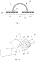
- the body fluid collection device 10 shown in FIG. 1 is one embodiment of the present invention.
- the body fluid collection device 10 includes a fitting part 11 having an opening 12, and a collection film 21.
- the fitting part 11 is a sheet having a first surface and a second surface opposite to the first surface, and an adhesive layer 13 is disposed on the first surface for adhering to a user.
- the collection film 21 has an edge having a circumference greater than a circumference of the opening 12 of the fitting part 11 and connected to the second surface of the fitting part 11 in a manner of surrounding the opening 12 of the fitting part 11.
- the edge of the collection film 21 may be connected to the second surface of the fitting part 11 along a circle, an ellipse or a rounded regular polygon.
- the opening 12 is located at the center of the circle, the ellipse or the rounded regular polygon.
- the collection film 21 has a pocket structure, the pocket structure having an open end defined by the edge of the collection film 21, and the open end being connected to the second surface of the fitting part 11.
- the material of the collection film 21 is preferably having elasticity, but a material having no elasticity can also be used. If a material having a high elasticity is used, the collection film 21 may also be manufactured as a planar or curved film.
- the body fluid collection device 10 may be manufactured by using, for example, but not limited to, natural latex, synthetic latex, rubber, silica gel, polyisoprene (PI), polyurethane (PU), polymeric materials, or biomaterials.
- the fitting part 11 may be, but not limited to, an elastic film which is a sheet having a planar or curved surface in a natural state, and preferably has a thickness of not more than 0.1 millimeter (mm), and the shape thereof may be, but not limited to, a circle, an ellipse or a rounded polygon.
- the constituent material of the adhesive layer 13 may include, for example, a pressure-sensitive adhesive.
- the pocket structure of the collection film 21 can be manufactured by using, for example, but not limited to, vacuum forming, compressed air forming, match mold forming, blow molding, 3D printing, or dip forming, and the thickness thereof is preferably not more than 0.1 mm.
- the edge of the collection film 21 and the second surface of the fitting part 11 may be connected by using, for example, but not limited to, a solvent, an adhesive, an adhesive tape or an adhesive film, or may be fusion-bonded(welded) by, for example, but not limited to, electrothermal heating, ultrasonic waves, high-frequency waves or the like.
- the collection film 21 may also be manufactured integrally with the fitting part 11.
- the joint of the edge of the collection film 21 and the second surface of the fitting part 11 has a width
- the inner edge of the joint (the edge adjacent to the opening 12) forms a connecting rim 22 surrounding the opening 12
- the circumference of the connecting rim 22 is greater than the circumference of the opening 12, thereby dividing the fitting part 11 into an inner portion 111 and an outer portion 112. That is, there is a distance between the connecting edge 22 and the opening 12, the inner edge of the fitting part 11 (the edge of the opening 12) and the connecting rim 22 define the inner portion 111, and the connecting rim 22 and the outer edge of the fitting part 11 define the outer portion 112.
- the inner portion 111 of the fitting part 11 and the collection film 21 constitute a storage space having the opening 12, which can be used for storing the body fluid of the user.
- the circular connecting rim 22 and the opening 12 at the center of the circle in FIG. 1 are merely exemplified.
- the connecting rim 22 may also be configured as another regular shape, for example, a rounded regular polygon, preferably a circle or an ellipse, and the opening 12 is not limited to being located at the center of the area surrounded by the connecting rim 22.
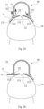
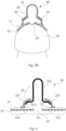
- FIG. 2A to FIG. 2D are schematic views showing a use mode of the body fluid collection device 10 from different perspectives: FIG. 2A is a three-dimensional view, FIG. 2B is a bottom view, FIG. 2C is a top view, and FIG. 2D is a side view.
- the collection film 21 has a transparent pocket structure, the pocket structure having an open end defined by the edge of the collection film 21. In the case where the collection film 21 and the fitting part 11 are connected in a fusion manner, as shown in FIG.
- the open end of the collection film 21 is connected to the second surface of the circular (or elliptical) fitting part 11 along a circle (or ellipse) in a fusion manner, and the joint has a width preferably greater than or equal to 1 mm.
- the opening 12 is aligned with the urethra orifice 71 of the user, the top edge 14 of the fitting part 11 faces the abdomen 72 of the user, the bottom edge 15 of the fitting part 11 faces the scrotum 73 of the user, the part of the fitting part 11 from the opening 12 to the bottom edge 15 is adhered by the adhesive layer (not shown) to the frenulum 75 below the glans penis 74 and a part of the corona glandis 76 adjacent to the scrotum 73 (shown in FIG. 2B ), the part of the fitting part 11 from the opening 12 to the top edge 14 is adhered by the adhesive layer to the glans penis 74 (shown in FIG.
- the nerve-filled glans penis 74 can be exposed to a larger extent, thereby increasing the user's pleasure in performing sexual behaviors.
- the elastic fitting part 11 can be applied to the glans penis 74 of different sizes or different curved surfaces in addition to easy attachment.
- the body fluid collection device 10 of the present invention is suitable for adhering to the glans penis when used as a male contraceptive device.
- the outer edge of the fitting part 11 should not exceed a radial vertical line Y (the vertical line Y is perpendicular to a central axis of the penis) of the corona glandis 76 passing through the adjacent abdomen 72. Therefore, the maximum width of the fitting part 11 can be, for example, less than 90 mm, preferably less than 70 mm, and more preferably less than 50 mm, so that the nerve-filled penis can be less covered.
- the circumference of the connecting rim 22 is less than the circumference of a general penis, for example, less than 150 mm, preferably less than 120 mm, and more preferably less than 90 mm, so that the area where the penis is covered by two layers of the materials (including the inner portion 111 of the fitting part 11 and the collection film 21) is smaller, thereby increasing the user's pleasure.
- the depth of the pocket of the collection film 2 1 is greater than the circumference of the connecting rim 22 divided by 6.28, for example greater than 10 mm, preferably greater than 20 mm, and more preferably greater than 30 mm, to accommodate more semen.
- the manufacturing process is relatively simple.
- the edge of the collection film 21 is smaller than the outer edge of the fitting part 11, when the present invention is used as a male contraceptive device, it is possible to prevent an excessively thick edge from scratching the vaginal wall and causing discomfort to a female, and also to prevent the outer edge of the fitting part 11 from being rolled up to cause peeling due to excessive thickness.
- the edge of the collection film 21 keeps a distance from the outer edge of the fitting part 11 (i.e. not in contact with the outer edge of the fitting part 11), and the distance is preferably greater than 2 mm. As shown in FIG.
- the collection film 21 can be prevented from being ripped due to friction of the vaginal wall and pulling of the collection film 21 during the stroking motion.
- the inner portion 111 of the fitting part 11 is adhered to the glans penis 74 by the adhesive layer 13, so that effectively preventing the fitting part 11 from being peeled off.
- FIG. 2E when the body fluid collection device 10 is in use, the fitting part 11 is adhered to the glans penis 74 by the adhesive layer 13, so that the inner portion 111 presents a curved surface facing the storage space. Therefore, inside the storage space, an angle A1 is formed between the opening 12 and body fluid collection device 10 (i.e., the inner portion 111 of the fitting part 11) immediately adjacent to the opening 12, and the angle A1 is a straight angle or a reflex angle facing the storage space.
- the angle A1 formed between the surface of the glans penis 74 and the body fluid collection device 10 is a straight angle or a reflex angle, the body fluid is less likely to leak from the opening 12 along a gap between the fitting part 11 and the glans penis 74 towards the edge of the fitting part 11.
- a closed structure formed by the inner portion 111 of the fitting part 11 adhering to the glans penis 74 and the collection film 21 can withstand the pressure F1 of the body fluid and/or internal air, so that the body fluid in the storage space is less likely to leak from the edge of the fitting part 11.
- the inner portion 111 and the outer portion 112 of the fitting part 11 are adhered to the glans penis 74 by the adhesive layer 13, and with the connecting rim 22 as a reference point, a bilateral fixing effect is generated on the inner side and the outer side respectively, thereby offsetting the pulling force generated by the collection film 21 which is expanded when filled with body fluid and/or air against the fitting part 11 (for example, the pulling force F2 shown in FIG.
- the widest part of the outer portion 112 of the fitting part 11 may, for example, have a width greater than 2 mm, preferably greater than 4 mm, more preferably greater than 6 mm, or greater than the circumference of the connecting rim 22 divided by 31.4.
- the fitting part 11 may be peeled off from the glans penis 74 in a direction from the edge to the opening 12.
- the outer portion 112 of the fitting part 11 is peeled off and the inner portion 111 is partially peeled off, as long as the inner portion 111 adjacent to the opening 12 still partially adheres to the glans penis 74, the semen in the storage space will not leak.
- the body fluid collection device 10 of the present invention has a simple structure and has the functions of collecting urine, prostatic fluid and semen and being contraceptive.
- Other variations of the body fluid collection device of the present invention will now be described with reference to the related drawings as embodiments of a male contraceptive device.
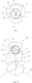
- FIG. 3 shows another embodiment of the body fluid collection device 10 of the present invention.
- a front view of the glans penis 74 of the user is illustrated in FIG. 3 .
- the collection film 21 is a transparent circular planar elastic film, and the distance between the arc shape top edge 14 of the fitting part 11 and the arc shape bottom edge 15 is greater than the distance between the two side edges of the fitting part 11.
- the distance between the two side edges of the fitting part 11 is small, when the user uses the body fluid collection device 10 as a male contraceptive device, the user's pleasure can be increased since the two sides of the glans penis 74 are exposed more.
- the edge of the fitting part 11 may have at least one notch, preferably an arc shape notch.
- the collection film 21 is a transparent circular curved elastic film, and two arc shape notches 16 are provided at the alignment between the two side edges of the fitting part 11 and the opening 12 respectively.
- the surface of the penis where the frenulum 75 meets the corona glandis 76 adjacent to the scrotum 73 is uneven, and at the same time is also a region that receives the greatest frictional force caused during the piston motion. Accordingly, the part of the fitting part 11 from the opening 12 to the bottom edge 15 is longer than the part of the fitting part 11 from the opening 12 to the top edge 14, so that the bottom edge 15 can extend to adhere to the raphe of penis 77.
- the fitting part 11 is substantially in a rounded rectangle (shown in FIG. 4A )
- the opening 12 is located on a long symmetry axis of the rounded rectangle (the long symmetry axis is in the vertical direction in FIG.
- the short symmetry axis is in the horizontal direction in FIG. 4A ). That is, the distances between the opening 12 and the two short sides of the rectangle (the two outer edges of the fitting part 11 on the long symmetry axis) are not equal, so that the fitting part 11 can be adhered more firmly and is not easy to peel off.
- the top edge 14 or the bottom edge 15 of the fitting part 11 may be linear, and is approximately perpendicular to the raphe of penis 77 in use.
- the linear top edge 14 or the bottom edge 15 is perpendicular to the direction of the piston motion, it can withstand more friction force caused during the piston motion than the edge of the circular arc, so that the fitting part 11 is less likely to be peeled off from the top edge 14 or the bottom edge 15.
- the edge of the rounded polygonal transparent collection film 21 is connected to the second surface of the fitting part 11 along a rounded regular hexagon, and the bottom edge 15 of the fitting part 11 may be longer than the top edge 14, so that the fitting part 11 is in a structure having a narrow top and a wide bottom.
- the fitting part 11 may be in a rounded polygon (the fitting part 11 disclosed in FIG. 4B is substantially hexagonal) having a symmetry axis (vertical direction in FIG. 4B ) and a first side and a second side (the top edge 14 and the bottom edge 15 in FIG. 4B ) perpendicular to the symmetry axis, the length of the first side is not equal to the length of the second side, and the opening 12 is located on the symmetry axis.
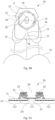
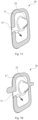
- FIG. 5A is another embodiment of the body fluid collection device 10 of the present invention.
- the collection film 21 has a pocket structure. Before the body fluid collection device 10 is used, the closed end of the pocket structure is inverted or folded inward toward the center of the open end, so that the inner surface 21i of the closed end is close to the fitting part 11.
- a retaining part 23 may be further disposed on the outer side, and close to the open end, of the collection film 21.
- the retaining part 23 may be a planar or radially curved sheet and has at least one retaining part opening 24, and the outer edge of the retaining part 23 is connected to the outer side of the pocket structure at a position close to the open end.
- the retaining part 23 can accommodate most of the folded-back collection film 21, thereby preventing the collection film 21 from being excessively pulled due to the piston motion, and allowing the collection film 21 to be folded outwards via the retaining part opening 24 due to receiving semen when the user ejaculates, so that the collection film 21 restores to the state before the folding back (shown in FIG. 5B ).
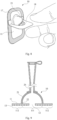
- FIG. 6 is another embodiment of the present invention.
- the body fluid collection device 10 includes a fitting part 11, and a collection film 21 including an annular part 211 and a pocket part 212.
- the annular part 211 is a planar or radially curved annular film, and the outer edge of the annular part is the edge of the collection film 21.
- the pocket part 212 has an open end, and the open end has a circumference greater than the circumference of the inner edge of the annular part 211 and is connected to the inner surface 211i of the annular part 211. That is, there is a distance between the inner edge of the annular part 211 and the joint of the open end of the pocket part 212 and the inner surface 211i of the annular part 211.
- the inner portion 111 of the fitting part 11, a part of the annular part 211, and the pocket part 212 constitute a storage space having an opening 12 and used for storing the prostatic fluid or semen of the user.
- the annular part 211 and the pocket part 212 may be made of the same or different materials, and have the same or different thicknesses.
- FIG. 7A shows one embodiment of the present invention.
- the body fluid collection device 10 may include a structure holding part 17 extending along the edge of the fitting part 11 as if a frame is provided on the fitting part 11 for holding the shape of the edge of the fitting part 11 before fitting, thereby avoiding generating wrinkles when the fitting part 11 is adhered to the glans penis 74 of the user. Since the structure holding part 17 is adhered to the second surface of the fitting part 11 by the weak adhesive, that is, the bonding force between the structure holding part 17 and the fitting part 11 is smaller than the bonding force between the fitting part 11 and the glans penis 74, the user does not peel the fitting part 11 from the glans penis 74 when the structure holding part 17 is removed.
- a part of the outer edge of the structure holding part 17 is further extendable to form at least one fin protruding from the fitting part 11 (shown in FIG. 7B ) for the user to grip with fingers.
- FIG. 8 shows one embodiment of the present invention.
- the body fluid collection device 10 includes a griping part 18 having at least one point connected to the structure holding part 17.
- the griping part 18 may be folded to be flattened to the fitting part 11 or the structure holding part 17, or pulled to a position at an angle of about 90 degrees with the fitting part 11 for the user to grip with fingers so as to adhere or adjust the body fluid collection device 10 or remove the structure holding part 17.
- FIG. 9 shows one embodiment of the present invention, in which the collection film 21 has a pocket structure having a connecting hole in addition to an open end (defined by the edge of the collection film 21) connected to the fitting part 11.
- the connecting hole is connected to a drainage tube 26, and the end of the drainage tube 26 may be, but not limited to, a flared joint, and may be connected with a cover to close the flared joint, so that the body fluid (such as semen or urine) stored in the storage space can be introduced into a container (such as a test tube or a urine bag) at certain intervals.
- a container such as a test tube or a urine bag
Landscapes
- Health & Medical Sciences (AREA)
- Life Sciences & Earth Sciences (AREA)
- Animal Behavior & Ethology (AREA)
- General Health & Medical Sciences (AREA)
- Engineering & Computer Science (AREA)
- Biomedical Technology (AREA)
- Heart & Thoracic Surgery (AREA)
- Veterinary Medicine (AREA)
- Public Health (AREA)
- Medical Informatics (AREA)
- Hematology (AREA)
- Surgery (AREA)
- Molecular Biology (AREA)
- Pathology (AREA)
- Reproductive Health (AREA)
- Vascular Medicine (AREA)
- Epidemiology (AREA)
- Nursing (AREA)
- Orthopedic Medicine & Surgery (AREA)
- Orthopedics, Nursing, And Contraception (AREA)
- Sampling And Sample Adjustment (AREA)
- Investigating Or Analysing Biological Materials (AREA)
Applications Claiming Priority (3)
| Application Number | Priority Date | Filing Date | Title |
|---|---|---|---|
| CN201710021718 | 2017-01-12 | ||
| CN201810008717.9A CN107874790B (zh) | 2017-01-12 | 2018-01-04 | 体液收集装置 |
| PCT/CN2018/000012 WO2018130103A1 (zh) | 2017-01-12 | 2018-01-09 | 体液收集装置 |
Publications (4)
| Publication Number | Publication Date |
|---|---|
| EP3569205A1 EP3569205A1 (en) | 2019-11-20 |
| EP3569205A4 EP3569205A4 (en) | 2020-07-22 |
| EP3569205B1 true EP3569205B1 (en) | 2023-06-28 |
| EP3569205C0 EP3569205C0 (en) | 2023-06-28 |
Family
ID=61770569
Family Applications (1)
| Application Number | Title | Priority Date | Filing Date |
|---|---|---|---|
| EP18738617.2A Active EP3569205B1 (en) | 2017-01-12 | 2018-01-09 | Bodily fluid collection apparatus |
Country Status (14)
| Country | Link |
|---|---|
| US (1) | US11234858B2 (enExample) |
| EP (1) | EP3569205B1 (enExample) |
| JP (1) | JP7054247B2 (enExample) |
| KR (1) | KR102539260B1 (enExample) |
| CN (1) | CN107874790B (enExample) |
| AU (1) | AU2018207127B2 (enExample) |
| CA (1) | CA3049813C (enExample) |
| ES (1) | ES2954371T3 (enExample) |
| MX (1) | MX2019008144A (enExample) |
| PH (1) | PH12019501608A1 (enExample) |
| PL (1) | PL3569205T3 (enExample) |
| RU (1) | RU2754885C2 (enExample) |
| SG (1) | SG11201906483PA (enExample) |
| WO (1) | WO2018130103A1 (enExample) |
Cited By (30)
| Publication number | Priority date | Publication date | Assignee | Title |
|---|---|---|---|---|
| US12186229B2 (en) | 2021-01-19 | 2025-01-07 | Purewick Corporation | Variable fit fluid collection devices, systems, and methods |
| US12208031B2 (en) | 2020-10-21 | 2025-01-28 | Purewick Corporation | Adapters for fluid collection devices |
| US12233003B2 (en) | 2021-04-29 | 2025-02-25 | Purewick Corporation | Fluid collection assemblies including at least one length adjusting feature |
| US12239567B2 (en) | 2014-03-19 | 2025-03-04 | Purewick Corporation | Apparatus and methods for receiving discharged urine |
| US12245966B2 (en) | 2021-02-26 | 2025-03-11 | Purewick Corporation | Fluid collection devices having a sump between a tube opening and a barrier, and related systems and methods |
| US12251333B2 (en) | 2021-05-21 | 2025-03-18 | Purewick Corporation | Fluid collection assemblies including at least one inflation device and methods and systems of using the same |
| US12257174B2 (en) | 2020-10-21 | 2025-03-25 | Purewick Corporation | Fluid collection assemblies including at least one of a protrusion or at least one expandable material |
| US12257173B2 (en) | 2017-01-31 | 2025-03-25 | Purewick Corporation | Apparatus and methods for receiving discharged urine |
| US12268627B2 (en) | 2021-01-06 | 2025-04-08 | Purewick Corporation | Fluid collection assemblies including at least one securement body |
| US12274638B2 (en) | 2018-05-01 | 2025-04-15 | Purewick Corporation | Fluid collection devices, related systems, and related methods |
| US12285352B2 (en) | 2018-05-01 | 2025-04-29 | Purewick Corporation | Fluid collection devices, systems, and methods |
| US12290485B2 (en) | 2020-11-11 | 2025-05-06 | Purewick Corporation | Urine collection system including a flow meter and related methods |
| WO2025095925A1 (en) * | 2023-10-30 | 2025-05-08 | Purewick Corporation | An elongated handle configured to hold a fluid collection assembly during positioning |
| US12295876B2 (en) | 2018-05-01 | 2025-05-13 | Purewick Corporation | Fluid collection devices and methods of using the same |
| US12324767B2 (en) | 2021-05-24 | 2025-06-10 | Purewick Corporation | Fluid collection assembly including a customizable external support and related methods |
| US12329364B2 (en) | 2019-07-19 | 2025-06-17 | Purewick Corporation | Fluid collection devices including at least one shape memory material |
| US12350187B2 (en) | 2020-08-11 | 2025-07-08 | Purewick Corporation | Fluid collection assemblies defining waist and leg openings |
| US12350190B2 (en) | 2020-01-03 | 2025-07-08 | Purewick Corporation | Urine collection devices having a relatively wide portion and an elongated portion and related methods |
| US12419778B2 (en) | 2019-06-21 | 2025-09-23 | Purewick Corporation | Fluid collection devices including a base securement area, and related systems and methods |
| US12440370B2 (en) | 2020-10-21 | 2025-10-14 | Purewick Corporation | Apparatus with compressible casing for receiving discharged urine |
| US12440371B2 (en) | 2020-08-06 | 2025-10-14 | Purewick Corporation | Fluid collection system including a garment and a fluid collection device |
| US12447042B2 (en) | 2020-04-17 | 2025-10-21 | Purewick Corporation | Fluid collection assemblies including a fluid impermeable barrier having a sump and a base |
| US12458525B2 (en) | 2021-03-10 | 2025-11-04 | Purewick Corporation | Acoustic silencer for a urine suction system |
| US12465514B2 (en) | 2020-04-17 | 2025-11-11 | Purewick Corporation | Fluid collection devices, systems, and methods securing a protruding portion in position for use |
| US12465515B2 (en) | 2019-10-28 | 2025-11-11 | Purewick Corporation | Fluid collection assemblies including a sample port |
| US12472090B2 (en) | 2020-04-17 | 2025-11-18 | Purewick Corporation | Female external catheter devices having a urethral cup, and related systems and methods |
| US12478499B2 (en) | 2021-01-07 | 2025-11-25 | Purewick Corporation | Wheelchair securable urine collection systems and related methods |
| US12491104B2 (en) | 2020-04-20 | 2025-12-09 | Purewick Corporation | Fluid collection devices adjustable between a vacuum-based orientation and a gravity-based orientation, and related systems and methods |
| US12521288B2 (en) | 2020-03-26 | 2026-01-13 | Purewick Corporation | Multi-layer urine capture device and related methods |
| US12521272B2 (en) | 2020-09-09 | 2026-01-13 | Purewick Corporation | Fluid collection devices, systems, and methods |
Families Citing this family (9)
| Publication number | Priority date | Publication date | Assignee | Title |
|---|---|---|---|---|
| WO2020000994A1 (zh) * | 2018-06-26 | 2020-01-02 | 杨国煌 | 体液收集装置 |
| CN110292480B (zh) * | 2019-06-20 | 2022-07-01 | 杨国煌 | 体液收集装置 |
| EP3988059B1 (en) * | 2019-06-20 | 2024-12-18 | Yang, Kuo Huang | Fluid-carrying application |
| CN111067660A (zh) * | 2019-12-31 | 2020-04-28 | 黄卫玲 | 一种龟头贴片和该贴片的制作方法 |
| JP6837693B1 (ja) * | 2020-05-29 | 2021-03-03 | 株式会社オンリースタイル | 採精用シート |
| EP4608466A1 (en) | 2022-10-26 | 2025-09-03 | Nuceptive Labs, Inc. | Stimuli-responsive medical adhesive compositions, articles, and methods |
| WO2025172808A1 (en) * | 2024-02-14 | 2025-08-21 | Tang John Ing Ching | Adhesive pouch dressing |
| WO2025226939A1 (en) | 2024-04-24 | 2025-10-30 | Nuceptive Labs, Inc. | Enhanced sensation condom |
| CN119498900B (zh) * | 2024-12-19 | 2025-09-12 | 西北工业大学 | 一种用于妇科临床的阴道分泌物取样装置 |
Family Cites Families (24)
| Publication number | Priority date | Publication date | Assignee | Title |
|---|---|---|---|---|
| JPS488157Y1 (enExample) * | 1968-10-08 | 1973-03-02 | ||
| US3677225A (en) * | 1970-10-01 | 1972-07-18 | Julius Czirely | Contraceptive device |
| US4626250A (en) * | 1981-06-05 | 1986-12-02 | Hollister Incorporated | Male urinary collection system and external catheter therefor |
| US4713066A (en) * | 1986-03-20 | 1987-12-15 | Glenna Komis | External male urinary catheter with garment |
| US4738673A (en) * | 1987-02-09 | 1988-04-19 | Barry Shepard | Catheter for detecting calculi |
| US4869269A (en) * | 1987-02-13 | 1989-09-26 | Sharkan Arnold L | Contraceptive device: micro-condom |
| CN2086596U (zh) * | 1991-01-28 | 1991-10-16 | 谭泽林 | 避孕帖 |
| CN2117865U (zh) * | 1992-04-11 | 1992-10-07 | 泸州医学院附属医院 | 粘贴式排尿管 |
| US5421350A (en) * | 1994-03-07 | 1995-06-06 | Friedman; Leah | Condom having adhesive means |
| US5513654A (en) | 1994-06-10 | 1996-05-07 | New Designs Corporation | Slip-resistant contraceptive male condom |
| RU1620U1 (ru) * | 1994-07-14 | 1996-02-16 | Валерьян Виссарионович Хабурзания | Устройство для сбора мочи у детей раннего возраста |
| US5458114A (en) * | 1995-04-14 | 1995-10-17 | Herr; Jan E. | Contraceptive penile cap |
| FR2750854B1 (fr) * | 1996-07-12 | 1999-01-22 | Delcroix Michel | Preservatif feminin |
| US6145507A (en) * | 1999-04-20 | 2000-11-14 | Hardy; Timothy J. | Abbreviated condom device |
| CN2702722Y (zh) * | 2004-01-30 | 2005-06-01 | 石新元 | 男用避孕安全粘贴 |
| CN101036605A (zh) * | 2006-03-16 | 2007-09-19 | 邹宗煊 | 一种安全贴及其制作方法 |
| CN101053539A (zh) * | 2006-04-13 | 2007-10-17 | 苏永军 | 一种安全套扩口环 |
| US20120029452A1 (en) | 2009-03-31 | 2012-02-02 | Urologic Aps | Urine collection system |
| US20130213415A1 (en) | 2012-02-22 | 2013-08-22 | Dennis M. Kay | Para-meatal/stomal Adhesive Sealing Device |
| WO2014041534A1 (en) | 2012-09-12 | 2014-03-20 | Gr Dome Medical Ltd | Glans penis attachment condom |
| KR101396317B1 (ko) * | 2013-04-30 | 2014-05-16 | 오시훈 | 남성용 피임기구 |
| KR101496092B1 (ko) | 2014-05-15 | 2015-02-25 | 오시훈 | 남성용 피임기구 |
| CN104490511A (zh) * | 2014-12-23 | 2015-04-08 | 薛剑 | 一种避孕套配合用具及其制作方法 |
| CN204971790U (zh) * | 2015-09-30 | 2016-01-20 | 冷安平 | 一种男士避孕贴 |
-
2018
- 2018-01-04 CN CN201810008717.9A patent/CN107874790B/zh active Active
- 2018-01-09 CA CA3049813A patent/CA3049813C/en active Active
- 2018-01-09 ES ES18738617T patent/ES2954371T3/es active Active
- 2018-01-09 JP JP2019527558A patent/JP7054247B2/ja active Active
- 2018-01-09 AU AU2018207127A patent/AU2018207127B2/en active Active
- 2018-01-09 RU RU2019124672A patent/RU2754885C2/ru active
- 2018-01-09 KR KR1020197022542A patent/KR102539260B1/ko active Active
- 2018-01-09 PL PL18738617.2T patent/PL3569205T3/pl unknown
- 2018-01-09 MX MX2019008144A patent/MX2019008144A/es unknown
- 2018-01-09 SG SG11201906483PA patent/SG11201906483PA/en unknown
- 2018-01-09 WO PCT/CN2018/000012 patent/WO2018130103A1/zh not_active Ceased
- 2018-01-09 US US16/477,528 patent/US11234858B2/en active Active
- 2018-01-09 EP EP18738617.2A patent/EP3569205B1/en active Active
-
2019
- 2019-07-09 PH PH12019501608A patent/PH12019501608A1/en unknown
Cited By (31)
| Publication number | Priority date | Publication date | Assignee | Title |
|---|---|---|---|---|
| US12239567B2 (en) | 2014-03-19 | 2025-03-04 | Purewick Corporation | Apparatus and methods for receiving discharged urine |
| US12324765B2 (en) | 2014-03-19 | 2025-06-10 | Purewick Corporation | Apparatus and methods for receiving discharged urine |
| US12257173B2 (en) | 2017-01-31 | 2025-03-25 | Purewick Corporation | Apparatus and methods for receiving discharged urine |
| US12274638B2 (en) | 2018-05-01 | 2025-04-15 | Purewick Corporation | Fluid collection devices, related systems, and related methods |
| US12285352B2 (en) | 2018-05-01 | 2025-04-29 | Purewick Corporation | Fluid collection devices, systems, and methods |
| US12295876B2 (en) | 2018-05-01 | 2025-05-13 | Purewick Corporation | Fluid collection devices and methods of using the same |
| US12419778B2 (en) | 2019-06-21 | 2025-09-23 | Purewick Corporation | Fluid collection devices including a base securement area, and related systems and methods |
| US12329364B2 (en) | 2019-07-19 | 2025-06-17 | Purewick Corporation | Fluid collection devices including at least one shape memory material |
| US12465515B2 (en) | 2019-10-28 | 2025-11-11 | Purewick Corporation | Fluid collection assemblies including a sample port |
| US12350190B2 (en) | 2020-01-03 | 2025-07-08 | Purewick Corporation | Urine collection devices having a relatively wide portion and an elongated portion and related methods |
| US12521288B2 (en) | 2020-03-26 | 2026-01-13 | Purewick Corporation | Multi-layer urine capture device and related methods |
| US12472090B2 (en) | 2020-04-17 | 2025-11-18 | Purewick Corporation | Female external catheter devices having a urethral cup, and related systems and methods |
| US12465514B2 (en) | 2020-04-17 | 2025-11-11 | Purewick Corporation | Fluid collection devices, systems, and methods securing a protruding portion in position for use |
| US12447042B2 (en) | 2020-04-17 | 2025-10-21 | Purewick Corporation | Fluid collection assemblies including a fluid impermeable barrier having a sump and a base |
| US12491104B2 (en) | 2020-04-20 | 2025-12-09 | Purewick Corporation | Fluid collection devices adjustable between a vacuum-based orientation and a gravity-based orientation, and related systems and methods |
| US12440371B2 (en) | 2020-08-06 | 2025-10-14 | Purewick Corporation | Fluid collection system including a garment and a fluid collection device |
| US12350187B2 (en) | 2020-08-11 | 2025-07-08 | Purewick Corporation | Fluid collection assemblies defining waist and leg openings |
| US12521272B2 (en) | 2020-09-09 | 2026-01-13 | Purewick Corporation | Fluid collection devices, systems, and methods |
| US12257174B2 (en) | 2020-10-21 | 2025-03-25 | Purewick Corporation | Fluid collection assemblies including at least one of a protrusion or at least one expandable material |
| US12440370B2 (en) | 2020-10-21 | 2025-10-14 | Purewick Corporation | Apparatus with compressible casing for receiving discharged urine |
| US12208031B2 (en) | 2020-10-21 | 2025-01-28 | Purewick Corporation | Adapters for fluid collection devices |
| US12290485B2 (en) | 2020-11-11 | 2025-05-06 | Purewick Corporation | Urine collection system including a flow meter and related methods |
| US12268627B2 (en) | 2021-01-06 | 2025-04-08 | Purewick Corporation | Fluid collection assemblies including at least one securement body |
| US12478499B2 (en) | 2021-01-07 | 2025-11-25 | Purewick Corporation | Wheelchair securable urine collection systems and related methods |
| US12186229B2 (en) | 2021-01-19 | 2025-01-07 | Purewick Corporation | Variable fit fluid collection devices, systems, and methods |
| US12245966B2 (en) | 2021-02-26 | 2025-03-11 | Purewick Corporation | Fluid collection devices having a sump between a tube opening and a barrier, and related systems and methods |
| US12458525B2 (en) | 2021-03-10 | 2025-11-04 | Purewick Corporation | Acoustic silencer for a urine suction system |
| US12233003B2 (en) | 2021-04-29 | 2025-02-25 | Purewick Corporation | Fluid collection assemblies including at least one length adjusting feature |
| US12251333B2 (en) | 2021-05-21 | 2025-03-18 | Purewick Corporation | Fluid collection assemblies including at least one inflation device and methods and systems of using the same |
| US12324767B2 (en) | 2021-05-24 | 2025-06-10 | Purewick Corporation | Fluid collection assembly including a customizable external support and related methods |
| WO2025095925A1 (en) * | 2023-10-30 | 2025-05-08 | Purewick Corporation | An elongated handle configured to hold a fluid collection assembly during positioning |
Also Published As
| Publication number | Publication date |
|---|---|
| CA3049813A1 (en) | 2018-07-19 |
| KR20190105603A (ko) | 2019-09-17 |
| SG11201906483PA (en) | 2019-08-27 |
| RU2019124672A (ru) | 2021-02-12 |
| JP7054247B2 (ja) | 2022-04-13 |
| WO2018130103A1 (zh) | 2018-07-19 |
| US20190358080A1 (en) | 2019-11-28 |
| MX2019008144A (es) | 2019-09-04 |
| RU2754885C2 (ru) | 2021-09-08 |
| US11234858B2 (en) | 2022-02-01 |
| AU2018207127B2 (en) | 2021-05-20 |
| PL3569205T3 (pl) | 2023-12-27 |
| EP3569205A4 (en) | 2020-07-22 |
| PH12019501608A1 (en) | 2020-03-16 |
| CA3049813C (en) | 2024-01-02 |
| CN107874790B (zh) | 2022-10-18 |
| JP2020513867A (ja) | 2020-05-21 |
| ES2954371T3 (es) | 2023-11-21 |
| EP3569205A1 (en) | 2019-11-20 |
| BR112019013868A2 (pt) | 2020-03-03 |
| CN107874790A (zh) | 2018-04-06 |
| KR102539260B1 (ko) | 2023-06-01 |
| RU2019124672A3 (enExample) | 2021-04-13 |
| AU2018207127A1 (en) | 2019-08-29 |
| EP3569205C0 (en) | 2023-06-28 |
Similar Documents
| Publication | Publication Date | Title |
|---|---|---|
| EP3569205B1 (en) | Bodily fluid collection apparatus | |
| CN211382099U (zh) | 体液收集装置 | |
| CN101626742A (zh) | 男性器官附件 | |
| TWI748979B (zh) | 男性避孕裝置 | |
| US7322358B2 (en) | Soft cling female condom | |
| US7823591B2 (en) | Female barrier contraceptive with vacuum anchoring | |
| TWM553183U (zh) | 男性避孕裝置 | |
| JP2017531505A (ja) | 非ロール状接着性コンドームおよび短尺コンドーム | |
| BR112019013868B1 (pt) | Dispositivo de coleta de fluido corporal | |
| CN211095141U (zh) | 新型龟头避孕套 | |
| CN102302394B (zh) | 男用舒适避孕栓 | |
| CN209203331U (zh) | 体液收集装置 | |
| KR101751438B1 (ko) | 성 보조기구 | |
| JP3049525U (ja) | 分娩促進バルーン | |
| WO2015193701A1 (en) | Adhesive condom with doule backing membranes | |
| JPS6235465Y2 (enExample) |
Legal Events
| Date | Code | Title | Description |
|---|---|---|---|
| STAA | Information on the status of an ep patent application or granted ep patent |
Free format text: STATUS: THE INTERNATIONAL PUBLICATION HAS BEEN MADE |
|
| PUAI | Public reference made under article 153(3) epc to a published international application that has entered the european phase |
Free format text: ORIGINAL CODE: 0009012 |
|
| STAA | Information on the status of an ep patent application or granted ep patent |
Free format text: STATUS: REQUEST FOR EXAMINATION WAS MADE |
|
| 17P | Request for examination filed |
Effective date: 20190807 |
|
| AK | Designated contracting states |
Kind code of ref document: A1 Designated state(s): AL AT BE BG CH CY CZ DE DK EE ES FI FR GB GR HR HU IE IS IT LI LT LU LV MC MK MT NL NO PL PT RO RS SE SI SK SM TR |
|
| AX | Request for extension of the european patent |
Extension state: BA ME |
|
| DAV | Request for validation of the european patent (deleted) | ||
| DAX | Request for extension of the european patent (deleted) | ||
| A4 | Supplementary search report drawn up and despatched |
Effective date: 20200624 |
|
| RIC1 | Information provided on ipc code assigned before grant |
Ipc: A61B 10/00 20060101ALI20200618BHEP Ipc: A61F 6/04 20060101AFI20200618BHEP Ipc: A61F 5/453 20060101ALI20200618BHEP |
|
| RIC1 | Information provided on ipc code assigned before grant |
Ipc: A61B 10/00 20060101ALI20221212BHEP Ipc: A61F 5/453 20060101ALI20221212BHEP Ipc: A61F 6/04 20060101AFI20221212BHEP |
|
| GRAP | Despatch of communication of intention to grant a patent |
Free format text: ORIGINAL CODE: EPIDOSNIGR1 |
|
| STAA | Information on the status of an ep patent application or granted ep patent |
Free format text: STATUS: GRANT OF PATENT IS INTENDED |
|
| INTG | Intention to grant announced |
Effective date: 20230124 |
|
| GRAS | Grant fee paid |
Free format text: ORIGINAL CODE: EPIDOSNIGR3 |
|
| GRAA | (expected) grant |
Free format text: ORIGINAL CODE: 0009210 |
|
| STAA | Information on the status of an ep patent application or granted ep patent |
Free format text: STATUS: THE PATENT HAS BEEN GRANTED |
|
| AK | Designated contracting states |
Kind code of ref document: B1 Designated state(s): AL AT BE BG CH CY CZ DE DK EE ES FI FR GB GR HR HU IE IS IT LI LT LU LV MC MK MT NL NO PL PT RO RS SE SI SK SM TR |
|
| REG | Reference to a national code |
Ref country code: CH Ref legal event code: EP |
|
| REG | Reference to a national code |
Ref country code: AT Ref legal event code: REF Ref document number: 1582071 Country of ref document: AT Kind code of ref document: T Effective date: 20230715 |
|
| REG | Reference to a national code |
Ref country code: IE Ref legal event code: FG4D |
|
| REG | Reference to a national code |
Ref country code: DE Ref legal event code: R096 Ref document number: 602018052427 Country of ref document: DE |
|
| U01 | Request for unitary effect filed |
Effective date: 20230721 |
|
| U07 | Unitary effect registered |
Designated state(s): AT BE BG DE DK EE FI FR IT LT LU LV MT NL PT SE SI Effective date: 20230727 |
|
| REG | Reference to a national code |
Ref country code: LT Ref legal event code: MG9D |
|
| PG25 | Lapsed in a contracting state [announced via postgrant information from national office to epo] |
Ref country code: NO Free format text: LAPSE BECAUSE OF FAILURE TO SUBMIT A TRANSLATION OF THE DESCRIPTION OR TO PAY THE FEE WITHIN THE PRESCRIBED TIME-LIMIT Effective date: 20230928 |
|
| REG | Reference to a national code |
Ref country code: ES Ref legal event code: FG2A Ref document number: 2954371 Country of ref document: ES Kind code of ref document: T3 Effective date: 20231121 |
|
| PG25 | Lapsed in a contracting state [announced via postgrant information from national office to epo] |
Ref country code: RS Free format text: LAPSE BECAUSE OF FAILURE TO SUBMIT A TRANSLATION OF THE DESCRIPTION OR TO PAY THE FEE WITHIN THE PRESCRIBED TIME-LIMIT Effective date: 20230628 Ref country code: HR Free format text: LAPSE BECAUSE OF FAILURE TO SUBMIT A TRANSLATION OF THE DESCRIPTION OR TO PAY THE FEE WITHIN THE PRESCRIBED TIME-LIMIT Effective date: 20230628 Ref country code: GR Free format text: LAPSE BECAUSE OF FAILURE TO SUBMIT A TRANSLATION OF THE DESCRIPTION OR TO PAY THE FEE WITHIN THE PRESCRIBED TIME-LIMIT Effective date: 20230929 |
|
| PG25 | Lapsed in a contracting state [announced via postgrant information from national office to epo] |
Ref country code: SK Free format text: LAPSE BECAUSE OF FAILURE TO SUBMIT A TRANSLATION OF THE DESCRIPTION OR TO PAY THE FEE WITHIN THE PRESCRIBED TIME-LIMIT Effective date: 20230628 |
|
| PG25 | Lapsed in a contracting state [announced via postgrant information from national office to epo] |
Ref country code: IS Free format text: LAPSE BECAUSE OF FAILURE TO SUBMIT A TRANSLATION OF THE DESCRIPTION OR TO PAY THE FEE WITHIN THE PRESCRIBED TIME-LIMIT Effective date: 20231028 |
|
| PG25 | Lapsed in a contracting state [announced via postgrant information from national office to epo] |
Ref country code: SM Free format text: LAPSE BECAUSE OF FAILURE TO SUBMIT A TRANSLATION OF THE DESCRIPTION OR TO PAY THE FEE WITHIN THE PRESCRIBED TIME-LIMIT Effective date: 20230628 Ref country code: SK Free format text: LAPSE BECAUSE OF FAILURE TO SUBMIT A TRANSLATION OF THE DESCRIPTION OR TO PAY THE FEE WITHIN THE PRESCRIBED TIME-LIMIT Effective date: 20230628 Ref country code: RO Free format text: LAPSE BECAUSE OF FAILURE TO SUBMIT A TRANSLATION OF THE DESCRIPTION OR TO PAY THE FEE WITHIN THE PRESCRIBED TIME-LIMIT Effective date: 20230628 Ref country code: IS Free format text: LAPSE BECAUSE OF FAILURE TO SUBMIT A TRANSLATION OF THE DESCRIPTION OR TO PAY THE FEE WITHIN THE PRESCRIBED TIME-LIMIT Effective date: 20231028 Ref country code: CZ Free format text: LAPSE BECAUSE OF FAILURE TO SUBMIT A TRANSLATION OF THE DESCRIPTION OR TO PAY THE FEE WITHIN THE PRESCRIBED TIME-LIMIT Effective date: 20230628 |
|
| U20 | Renewal fee for the european patent with unitary effect paid |
Year of fee payment: 7 Effective date: 20231228 |
|
| PG25 | Lapsed in a contracting state [announced via postgrant information from national office to epo] |
Ref country code: PL Free format text: LAPSE BECAUSE OF FAILURE TO SUBMIT A TRANSLATION OF THE DESCRIPTION OR TO PAY THE FEE WITHIN THE PRESCRIBED TIME-LIMIT Effective date: 20230628 |
|
| REG | Reference to a national code |
Ref country code: DE Ref legal event code: R097 Ref document number: 602018052427 Country of ref document: DE |
|
| PLBE | No opposition filed within time limit |
Free format text: ORIGINAL CODE: 0009261 |
|
| STAA | Information on the status of an ep patent application or granted ep patent |
Free format text: STATUS: NO OPPOSITION FILED WITHIN TIME LIMIT |
|
| 26N | No opposition filed |
Effective date: 20240402 |
|
| PG2D | Information on lapse in contracting state deleted |
Ref country code: PL |
|
| PG25 | Lapsed in a contracting state [announced via postgrant information from national office to epo] |
Ref country code: MC Free format text: LAPSE BECAUSE OF FAILURE TO SUBMIT A TRANSLATION OF THE DESCRIPTION OR TO PAY THE FEE WITHIN THE PRESCRIBED TIME-LIMIT Effective date: 20230628 |
|
| PG25 | Lapsed in a contracting state [announced via postgrant information from national office to epo] |
Ref country code: MC Free format text: LAPSE BECAUSE OF FAILURE TO SUBMIT A TRANSLATION OF THE DESCRIPTION OR TO PAY THE FEE WITHIN THE PRESCRIBED TIME-LIMIT Effective date: 20230628 |
|
| PGFP | Annual fee paid to national office [announced via postgrant information from national office to epo] |
Ref country code: GB Payment date: 20241224 Year of fee payment: 8 |
|
| PG25 | Lapsed in a contracting state [announced via postgrant information from national office to epo] |
Ref country code: IE Free format text: LAPSE BECAUSE OF NON-PAYMENT OF DUE FEES Effective date: 20240109 |
|
| U20 | Renewal fee for the european patent with unitary effect paid |
Year of fee payment: 8 Effective date: 20241224 |
|
| PG25 | Lapsed in a contracting state [announced via postgrant information from national office to epo] |
Ref country code: IE Free format text: LAPSE BECAUSE OF NON-PAYMENT OF DUE FEES Effective date: 20240109 |
|
| PGFP | Annual fee paid to national office [announced via postgrant information from national office to epo] |
Ref country code: ES Payment date: 20250210 Year of fee payment: 8 |
|
| PGFP | Annual fee paid to national office [announced via postgrant information from national office to epo] |
Ref country code: CH Payment date: 20250201 Year of fee payment: 8 |
|
| PGFP | Annual fee paid to national office [announced via postgrant information from national office to epo] |
Ref country code: PL Payment date: 20250103 Year of fee payment: 8 |
|
| PGFP | Annual fee paid to national office [announced via postgrant information from national office to epo] |
Ref country code: TR Payment date: 20250107 Year of fee payment: 8 |
|
| PG25 | Lapsed in a contracting state [announced via postgrant information from national office to epo] |
Ref country code: CY Free format text: LAPSE BECAUSE OF FAILURE TO SUBMIT A TRANSLATION OF THE DESCRIPTION OR TO PAY THE FEE WITHIN THE PRESCRIBED TIME-LIMIT; INVALID AB INITIO Effective date: 20180109 |
|
| PG25 | Lapsed in a contracting state [announced via postgrant information from national office to epo] |
Ref country code: HU Free format text: LAPSE BECAUSE OF FAILURE TO SUBMIT A TRANSLATION OF THE DESCRIPTION OR TO PAY THE FEE WITHIN THE PRESCRIBED TIME-LIMIT; INVALID AB INITIO Effective date: 20180109 |