EP3569174B1 - Treatment device for endoscope, endoscope, and expanding stent - Google Patents
Treatment device for endoscope, endoscope, and expanding stent Download PDFInfo
- Publication number
- EP3569174B1 EP3569174B1 EP18742335.5A EP18742335A EP3569174B1 EP 3569174 B1 EP3569174 B1 EP 3569174B1 EP 18742335 A EP18742335 A EP 18742335A EP 3569174 B1 EP3569174 B1 EP 3569174B1
- Authority
- EP
- European Patent Office
- Prior art keywords
- electrically conductive
- endoscope
- conductive part
- sheath
- electrode
- Prior art date
- Legal status (The legal status is an assumption and is not a legal conclusion. Google has not performed a legal analysis and makes no representation as to the accuracy of the status listed.)
- Active
Links
Images














Classifications
-
- A—HUMAN NECESSITIES
- A61—MEDICAL OR VETERINARY SCIENCE; HYGIENE
- A61B—DIAGNOSIS; SURGERY; IDENTIFICATION
- A61B18/00—Surgical instruments, devices or methods for transferring non-mechanical forms of energy to or from the body
- A61B18/04—Surgical instruments, devices or methods for transferring non-mechanical forms of energy to or from the body by heating
- A61B18/12—Surgical instruments, devices or methods for transferring non-mechanical forms of energy to or from the body by heating by passing a current through the tissue to be heated, e.g. high-frequency current
- A61B18/14—Probes or electrodes therefor
- A61B18/1492—Probes or electrodes therefor having a flexible, catheter-like structure, e.g. for heart ablation
-
- A—HUMAN NECESSITIES
- A61—MEDICAL OR VETERINARY SCIENCE; HYGIENE
- A61B—DIAGNOSIS; SURGERY; IDENTIFICATION
- A61B18/00—Surgical instruments, devices or methods for transferring non-mechanical forms of energy to or from the body
- A61B18/04—Surgical instruments, devices or methods for transferring non-mechanical forms of energy to or from the body by heating
- A61B18/12—Surgical instruments, devices or methods for transferring non-mechanical forms of energy to or from the body by heating by passing a current through the tissue to be heated, e.g. high-frequency current
-
- A—HUMAN NECESSITIES
- A61—MEDICAL OR VETERINARY SCIENCE; HYGIENE
- A61B—DIAGNOSIS; SURGERY; IDENTIFICATION
- A61B1/00—Instruments for performing medical examinations of the interior of cavities or tubes of the body by visual or photographical inspection, e.g. endoscopes; Illuminating arrangements therefor
- A61B1/012—Instruments for performing medical examinations of the interior of cavities or tubes of the body by visual or photographical inspection, e.g. endoscopes; Illuminating arrangements therefor characterised by internal passages or accessories therefor
- A61B1/018—Instruments for performing medical examinations of the interior of cavities or tubes of the body by visual or photographical inspection, e.g. endoscopes; Illuminating arrangements therefor characterised by internal passages or accessories therefor for receiving instruments
-
- A—HUMAN NECESSITIES
- A61—MEDICAL OR VETERINARY SCIENCE; HYGIENE
- A61B—DIAGNOSIS; SURGERY; IDENTIFICATION
- A61B18/00—Surgical instruments, devices or methods for transferring non-mechanical forms of energy to or from the body
- A61B18/04—Surgical instruments, devices or methods for transferring non-mechanical forms of energy to or from the body by heating
- A61B18/12—Surgical instruments, devices or methods for transferring non-mechanical forms of energy to or from the body by heating by passing a current through the tissue to be heated, e.g. high-frequency current
- A61B18/1206—Generators therefor
-
- A—HUMAN NECESSITIES
- A61—MEDICAL OR VETERINARY SCIENCE; HYGIENE
- A61B—DIAGNOSIS; SURGERY; IDENTIFICATION
- A61B90/00—Instruments, implements or accessories specially adapted for surgery or diagnosis and not covered by any of the groups A61B1/00 - A61B50/00, e.g. for luxation treatment or for protecting wound edges
- A61B90/36—Image-producing devices or illumination devices not otherwise provided for
- A61B90/361—Image-producing devices, e.g. surgical cameras
-
- A—HUMAN NECESSITIES
- A61—MEDICAL OR VETERINARY SCIENCE; HYGIENE
- A61B—DIAGNOSIS; SURGERY; IDENTIFICATION
- A61B1/00—Instruments for performing medical examinations of the interior of cavities or tubes of the body by visual or photographical inspection, e.g. endoscopes; Illuminating arrangements therefor
- A61B1/00064—Constructional details of the endoscope body
- A61B1/00071—Insertion part of the endoscope body
- A61B1/0008—Insertion part of the endoscope body characterised by distal tip features
- A61B1/00087—Tools
-
- A—HUMAN NECESSITIES
- A61—MEDICAL OR VETERINARY SCIENCE; HYGIENE
- A61B—DIAGNOSIS; SURGERY; IDENTIFICATION
- A61B1/00—Instruments for performing medical examinations of the interior of cavities or tubes of the body by visual or photographical inspection, e.g. endoscopes; Illuminating arrangements therefor
- A61B1/00112—Connection or coupling means
- A61B1/00121—Connectors, fasteners and adapters, e.g. on the endoscope handle
- A61B1/00124—Connectors, fasteners and adapters, e.g. on the endoscope handle electrical, e.g. electrical plug-and-socket connection
-
- A—HUMAN NECESSITIES
- A61—MEDICAL OR VETERINARY SCIENCE; HYGIENE
- A61B—DIAGNOSIS; SURGERY; IDENTIFICATION
- A61B1/00—Instruments for performing medical examinations of the interior of cavities or tubes of the body by visual or photographical inspection, e.g. endoscopes; Illuminating arrangements therefor
- A61B1/00131—Accessories for endoscopes
- A61B1/00133—Drive units for endoscopic tools inserted through or with the endoscope
-
- A—HUMAN NECESSITIES
- A61—MEDICAL OR VETERINARY SCIENCE; HYGIENE
- A61B—DIAGNOSIS; SURGERY; IDENTIFICATION
- A61B1/00—Instruments for performing medical examinations of the interior of cavities or tubes of the body by visual or photographical inspection, e.g. endoscopes; Illuminating arrangements therefor
- A61B1/00131—Accessories for endoscopes
- A61B1/00135—Oversleeves mounted on the endoscope prior to insertion
-
- A—HUMAN NECESSITIES
- A61—MEDICAL OR VETERINARY SCIENCE; HYGIENE
- A61B—DIAGNOSIS; SURGERY; IDENTIFICATION
- A61B1/00—Instruments for performing medical examinations of the interior of cavities or tubes of the body by visual or photographical inspection, e.g. endoscopes; Illuminating arrangements therefor
- A61B1/00131—Accessories for endoscopes
- A61B1/00137—End pieces at either end of the endoscope, e.g. caps, seals or forceps plugs
-
- A—HUMAN NECESSITIES
- A61—MEDICAL OR VETERINARY SCIENCE; HYGIENE
- A61B—DIAGNOSIS; SURGERY; IDENTIFICATION
- A61B18/00—Surgical instruments, devices or methods for transferring non-mechanical forms of energy to or from the body
- A61B18/04—Surgical instruments, devices or methods for transferring non-mechanical forms of energy to or from the body by heating
- A61B18/12—Surgical instruments, devices or methods for transferring non-mechanical forms of energy to or from the body by heating by passing a current through the tissue to be heated, e.g. high-frequency current
- A61B18/14—Probes or electrodes therefor
- A61B18/1442—Probes having pivoting end effectors, e.g. forceps
- A61B18/1445—Probes having pivoting end effectors, e.g. forceps at the distal end of a shaft, e.g. forceps or scissors at the end of a rigid rod
-
- A—HUMAN NECESSITIES
- A61—MEDICAL OR VETERINARY SCIENCE; HYGIENE
- A61B—DIAGNOSIS; SURGERY; IDENTIFICATION
- A61B18/00—Surgical instruments, devices or methods for transferring non-mechanical forms of energy to or from the body
- A61B18/04—Surgical instruments, devices or methods for transferring non-mechanical forms of energy to or from the body by heating
- A61B18/12—Surgical instruments, devices or methods for transferring non-mechanical forms of energy to or from the body by heating by passing a current through the tissue to be heated, e.g. high-frequency current
- A61B18/14—Probes or electrodes therefor
- A61B18/16—Indifferent or passive electrodes for grounding
-
- A—HUMAN NECESSITIES
- A61—MEDICAL OR VETERINARY SCIENCE; HYGIENE
- A61B—DIAGNOSIS; SURGERY; IDENTIFICATION
- A61B18/00—Surgical instruments, devices or methods for transferring non-mechanical forms of energy to or from the body
- A61B2018/00315—Surgical instruments, devices or methods for transferring non-mechanical forms of energy to or from the body for treatment of particular body parts
- A61B2018/00553—Sphincter
-
- A—HUMAN NECESSITIES
- A61—MEDICAL OR VETERINARY SCIENCE; HYGIENE
- A61B—DIAGNOSIS; SURGERY; IDENTIFICATION
- A61B18/00—Surgical instruments, devices or methods for transferring non-mechanical forms of energy to or from the body
- A61B2018/00571—Surgical instruments, devices or methods for transferring non-mechanical forms of energy to or from the body for achieving a particular surgical effect
- A61B2018/00589—Coagulation
-
- A—HUMAN NECESSITIES
- A61—MEDICAL OR VETERINARY SCIENCE; HYGIENE
- A61B—DIAGNOSIS; SURGERY; IDENTIFICATION
- A61B18/00—Surgical instruments, devices or methods for transferring non-mechanical forms of energy to or from the body
- A61B2018/00571—Surgical instruments, devices or methods for transferring non-mechanical forms of energy to or from the body for achieving a particular surgical effect
- A61B2018/00595—Cauterization
-
- A—HUMAN NECESSITIES
- A61—MEDICAL OR VETERINARY SCIENCE; HYGIENE
- A61B—DIAGNOSIS; SURGERY; IDENTIFICATION
- A61B18/00—Surgical instruments, devices or methods for transferring non-mechanical forms of energy to or from the body
- A61B2018/00571—Surgical instruments, devices or methods for transferring non-mechanical forms of energy to or from the body for achieving a particular surgical effect
- A61B2018/00601—Cutting
-
- A—HUMAN NECESSITIES
- A61—MEDICAL OR VETERINARY SCIENCE; HYGIENE
- A61B—DIAGNOSIS; SURGERY; IDENTIFICATION
- A61B18/00—Surgical instruments, devices or methods for transferring non-mechanical forms of energy to or from the body
- A61B2018/00982—Surgical instruments, devices or methods for transferring non-mechanical forms of energy to or from the body combined with or comprising means for visual or photographic inspections inside the body, e.g. endoscopes
-
- A—HUMAN NECESSITIES
- A61—MEDICAL OR VETERINARY SCIENCE; HYGIENE
- A61B—DIAGNOSIS; SURGERY; IDENTIFICATION
- A61B18/00—Surgical instruments, devices or methods for transferring non-mechanical forms of energy to or from the body
- A61B18/04—Surgical instruments, devices or methods for transferring non-mechanical forms of energy to or from the body by heating
- A61B18/12—Surgical instruments, devices or methods for transferring non-mechanical forms of energy to or from the body by heating by passing a current through the tissue to be heated, e.g. high-frequency current
- A61B18/1206—Generators therefor
- A61B2018/1246—Generators therefor characterised by the output polarity
- A61B2018/126—Generators therefor characterised by the output polarity bipolar
-
- A—HUMAN NECESSITIES
- A61—MEDICAL OR VETERINARY SCIENCE; HYGIENE
- A61B—DIAGNOSIS; SURGERY; IDENTIFICATION
- A61B18/00—Surgical instruments, devices or methods for transferring non-mechanical forms of energy to or from the body
- A61B18/04—Surgical instruments, devices or methods for transferring non-mechanical forms of energy to or from the body by heating
- A61B18/12—Surgical instruments, devices or methods for transferring non-mechanical forms of energy to or from the body by heating by passing a current through the tissue to be heated, e.g. high-frequency current
- A61B18/14—Probes or electrodes therefor
- A61B2018/1405—Electrodes having a specific shape
- A61B2018/1407—Loop
- A61B2018/141—Snare
-
- A—HUMAN NECESSITIES
- A61—MEDICAL OR VETERINARY SCIENCE; HYGIENE
- A61B—DIAGNOSIS; SURGERY; IDENTIFICATION
- A61B18/00—Surgical instruments, devices or methods for transferring non-mechanical forms of energy to or from the body
- A61B18/04—Surgical instruments, devices or methods for transferring non-mechanical forms of energy to or from the body by heating
- A61B18/12—Surgical instruments, devices or methods for transferring non-mechanical forms of energy to or from the body by heating by passing a current through the tissue to be heated, e.g. high-frequency current
- A61B18/14—Probes or electrodes therefor
- A61B2018/1467—Probes or electrodes therefor using more than two electrodes on a single probe
-
- A—HUMAN NECESSITIES
- A61—MEDICAL OR VETERINARY SCIENCE; HYGIENE
- A61B—DIAGNOSIS; SURGERY; IDENTIFICATION
- A61B18/00—Surgical instruments, devices or methods for transferring non-mechanical forms of energy to or from the body
- A61B18/04—Surgical instruments, devices or methods for transferring non-mechanical forms of energy to or from the body by heating
- A61B18/12—Surgical instruments, devices or methods for transferring non-mechanical forms of energy to or from the body by heating by passing a current through the tissue to be heated, e.g. high-frequency current
- A61B18/14—Probes or electrodes therefor
- A61B2018/1475—Electrodes retractable in or deployable from a housing
Definitions
- the present invention belongs to the field of medical instruments, and specifically, to a treatment apparatus for an endoscope.
- the present invention relates to a treatment apparatus for an endoscope of the generic type as defined in claim 1.
- Document US 2014/0188109 A1 discloses a treatment apparatus of the generic type defined above. Specifically, this document discloses a bipolar sphincterotome including an elongate tubular member, a cutting wire, and a return path.
- the return path includes a conductive ink portion disposed on an outer surface at a distal portion of the tubular member.
- the return path also includes a return wire disposed within the tubular member that is electrically coupled to the conductive ink portion.
- the return wire is disposed within a lumen configured to have two or more functions, one of which being to house the return wire.
- the conductive ink portion is circumferentially disposed on the outer surface to provide visual access to a wire guide lumen.
- Document US 2003/0181900 A1 discloses an endoscopic tissue ablation system including a plurality of electrode pairs and a viewing window between each pair of adjacent electrodes.
- the electrodes can be energized in a predetermined sequence to ablate tissue around the circumference of a body lumen.
- bipolar treatment instruments for an endoscope that are passed through endoscopes to treat living tissue and the like.
- Some of the bipolar treatment instruments for an endoscope have, for example, a function of supplying a high-frequency current to a treatment instrument to perform treatments such as incision, cauterization, and hemostasis on living tissue.
- a high-frequency incision instrument that uses a polypectomy snare supplied with a high-frequency current to incise living tissue is recorded in document CN 102 413 786 B .
- An electric wire, a passive electrode arranged on a periphery of an extending part, living tissue in contact with the passive electrode, the polypectomy snare, and an operating wire are connected to a feeding electrode to form a current loop to excise a polyp.
- a bipolar sphincterotome is recorded in document CN 205 697 995 U and includes a control part, an insulating sheath, and a cutting part.
- a distal end of the control part is connected to a proximal end of the insulating sheath.
- the cutting part includes a cutting electrode, a passive electrode, a cutting electrode wiring terminal that may be connected to the cutting electrode, a passive electrode wiring terminal that may be connected to the passive electrode, a cutting electrode conductor connecting the cutting electrode and the cutting electrode wiring terminal, and a passive electrode conductor connecting the passive electrode and the passive electrode wiring terminal.
- the cutting electrode and the passive electrode are provided on a distal end of the insulating sheath and are respectively connected to the control part through the cutting electrode conductor and the passive electrode conductor.
- an active electrode that is, the foregoing high-frequency treatment part and cutting part
- a cutting speed is relatively slow, resulting in limited clinical application.
- an area of contact between a passive electrode and tissue is relatively small, and tissue may be burned accidentally.
- the passive electrode and the active electrode are relatively close, the two electrodes may contact or a current may flow through tissue fluids between the electrodes to cause a short circuit failure.
- treatment instruments such as electrocoagulation forceps, biopsy forceps, needle knives, and the like in addition to snares and papilla incision knives need to be electrified to perform incision, cauterization, hemostasis, among other work.
- the passive electrode in the foregoing technical solution has relatively low adaptability.
- the present invention provides a treatment apparatus for an endoscope as defined in claim 1 attached.
- Preferred embodiments of the invention are defined in claims dependent upon claim 1 attached.
- the structural design is appropriate, the cutting speed is relatively high, the risk of passive electrode burns is relatively low, and adaptability is provided.
- the beneficial effects of the present invention are as follows:
- the first electrode performs an electrical operation on a human body, and a current that enters the human body is looped through the second electrically conductive part instead of flowing all over the human body, so as to avoid damage to other organs or electronic apparatuses (for example, a pacemaker) in the human body, thereby ensuring the safety of the entire operation.
- the second electrode may be provided at any position in the endoscope, so that a sufficiently large area of contact between the second electrically conductive part and the human body is ensured to fully guide out a current.
- a space of contact between an outer side of the endoscope body of the endoscope and tissue is fully used to increase a conductive area of a contact part through which a current is guided out from human body tissue in a return path, so that while the risk of burns is reduced, a thermal effect is further improved, thereby improving the security and operation efficiency of endoscopic surgery, and ensuring further clinical popularization and application of the treatment apparatus for an endoscope.
- Sheath 10 Sheath 10, first cavity 11, second cavity 12, operating wire 20, cutting part 21, ESD knife 222, electric snare 221, electrocoagulation forceps 223, electric biopsy forceps 224, conductor cavity 2251, cutting wire 2252, anchor 2253, drive part 30, sliding ring 31, endoscope body 401, instrument passage 403, transparent cover 41, expandable frame 42, return path 50, first electrically conductive part 51, second electrically conductive part 52, sliding contact part 53, third electrically conductive part 54, fourth electrically conductive part 55, feeding electrode 60, passive electrode 61, active electrode 62, tissue operation mechanism 70.
- a treatment apparatus for an endoscope includes: a first electrode, including an electrical treatment part and an operating wire 20; a second electrode, configured to be provided inside the endoscope (not shown), and including a first electrically conductive part 51 and a sliding contact part 53 electrically connected to the first electrically conductive part 51, the first electrically conductive part 51 being configured to contact a human body; and a sheath 10, provided on a surface thereof with a second electrically conductive part 52, where the operating wire 20 is passed through the sheath 10, the sheath 10 is passed through the endoscope, and the sheath 10 is movable back and forth in an instrument passage of the endoscope.
- the sheath 10 of the present invention is passed through the instrument passage 403 of the endoscope and is controlled by a drive part 30 (a sliding ring 31 is provided on the drive part 30) connected outside a body to move freely forward or backward in the instrument passage 403.
- a drive part 30 a sliding ring 31 is provided on the drive part 30
- a first cavity 11 extending in an axial direction and having openings at two ends is formed in the sheath 10.
- the sheath 10 is made of an insulating material, for example, insulating resin.
- the sheath 10 needs to be flexible enough to bend and move forward or backward along lumen tissue and the like in an organism.
- the conductive operating wire 20 is passed through the first cavity 11 in a manner of moving freely forward or backward.
- the electrical treatment part including, but is not limited to, an endoscopic submucosal dissection (ESD) knife 222, an electric snare 221, electrocoagulation forceps 223, electric biopsy forceps 224, and a papilla sphincterotomy hereinafter
- ESD endoscopic submucosal dissection
- the electrical treatment part is provided at a distal end of the operating wire 20, and in this embodiment, is an electric snare.
- the operating wire 20 is conductive.
- a proximal end of the operating wire 20 is electrically connected to an active electrode 62 of a feeding electrode 60 (in the present invention, the feeding electrode 60 includes a passive electrode 61 and the active electrode 62, referring to FIG. 14 for details).
- the operating wire 20 is conductive (or even the operating wire 20 and the electrical treatment part may be one overall conductor) in this embodiment, the specific material and performance of the operating wire 20 are not limited, provided that the electrical treatment part can be manipulated to move forward or backward.
- the operating wire 20 may be not conductive, and a conductor wire is additionally used between the electrical treatment part and an electrode to establish a conductive connection.
- the expandable frame 42 is sleeved over a front end of the endoscope. As shown in FIG. 2 and FIG. 3 .
- the expandable frame 42 includes a sleeve 411 sleeved over the endoscope and a transparent cover 41.
- the transparent cover 41 is made of a transparent insulating material.
- the transparent cover 41 may block a part of the view of a camera 402 (as shown in FIG. 1 and FIG. 2 ) of the endoscope, and the endoscope may obtain an image through the transparent cover 41.
- the first electrically conductive part 51 is provided on a periphery of the expandable frame. A diameter of a peripheral surface of the expandable frame is greater than a diameter of a peripheral surface of the endoscope.
- the sliding contact part 53 may be provided on the expandable frame.
- FIG. 5A , FIG. 5B , and FIG. 5C further show other implementations in which the expandable frame 42 is installed on the treatment apparatus for an endoscope.
- the expandable frame 42 is assembled at a distal end of an endoscope body 401 of the endoscope, the first electrically conductive part 51 is provided on a periphery of the expandable frame, and the first electrically conductive part 51 has a relatively large surface area to fully contact human body tissue.
- a structure of the first electrically conductive part 51 may be as follows: A conductive material is provided on a peripheral surface of the endoscope 42, and the conductive material forms the first electrically conductive part 51. The type of the conductive material may be selected as required.
- the sliding contact part 53 is provided on the expandable frame 42 and has conductive performance. A part of the sliding contact part 53 is electrically connected to the first electrically conductive part 51, and another part of the sliding contact part 53 forms tight fit with a periphery of the sheath and is electrically connected to the second electrically conductive part 52.
- the expandable frame 42 with a transparent cap 41 is provided in the foregoing embodiment, the foregoing two structures are not limited, provided that is an auxiliary apparatus for an endoscope can be tightly attached to a side wall of tissue and has a larger surface area than the sheath, so that the first electrically conductive part 51 may be attached to the peripheral surface of the peripheral surface of the expandable frame 42 and is connected to the second electrically conductive part 52 through the sliding contact part 53 to achieve the same effect.
- an auxiliary apparatus for an endoscope can be tightly attached to a side wall of tissue and has a larger surface area than the sheath, so that the first electrically conductive part 51 may be attached to the peripheral surface of the peripheral surface of the expandable frame 42 and is connected to the second electrically conductive part 52 through the sliding contact part 53 to achieve the same effect.
- the expandable frame 42 includes a sleeve 411' and a flexible part or an elastic part 412 connected to the sleeve 411', the sleeve 411' is configured to be sleeved over the endoscope, and the sliding contact part 53 is fixed on an inner side of the expandable frame or an inner side of the sleeve 411'.
- the flexible part or elastic part 412 provides particular cushioning for the sliding contact part 53 or applies particular pressure to keep electrical contact between the sliding contact part 53 and the second electrically conductive part 52, so that the sliding contact part 53 is kept being configured to be electrically connected to the second electrically conductive part 52.
- the second electrically conductive part 52 is fixed at a position, at a distance of L1 near a top end, on a periphery of a front section of the sheath 10, and is conductive.
- An outer diameter of the second electrically conductive part 52 does not exceed an inner diameter of the instrument passage 403.
- the second cavity 12 is formed in the sheath 10.
- a third electrically conductive part 54 having a conductive function is encapsulated in the second cavity 12.
- the second electrically conductive part 52 is electrically connected to the third electrically conductive part 54, and the second electrically conductive part 52 is electrically connected to a passive electrode 61 of the feeding electrode 60 through the third electrically conductive part 54, and an external power supply supplies power to the electric snare.
- the present invention is not limited thereto.
- a layer of a conductive material is provided on an outer surface of the sheath 10, and the conductive material forms the second electrically conductive part 52.
- the type of the conductive material may be selected as required.
- the layer of the conductive material at least covers a peripheral surface of a part of the sheath 10.
- the layer of the conductive material may be made very thin to reduce an increase in an additional volume.
- the layer of the conductive material is made smooth to facilitate the movement of the sheath 10 in the instrument passage of the endoscope.
- FIG. 4 shows several arrangement manners of the third electrically conductive part 54 in the sheath 12.
- the third electrically conductive part 54 has a linear shape in this embodiment, the specific shape and structure of the third electrically conductive part 54 are not limited, provided that the third electrically conductive part 54 can electrically connect the first electrically conductive part 51 to the feeding electrode and can bend in accordance with a flexible cavity.
- the expandable frame 42 with the first electrically conductive part 51 is assembled at a distal end of an endoscope body 401 of the endoscope, and the sheath 10 with the electric snare 221 is further inserted in the instrument passage 403 of the endoscope.
- the endoscope is inserted in a cavity (for example, a digestive tract, a vagina) of a human body, and an image transmitted by the camera 402 is simultaneously observed.
- the feeding electrode 60 is turned on, and a current flows through the active electrode 62 of the feeding electrode 60, the electric snare 221, the tissue to be excised, and a return path 50 (as shown in FIG. 12 , the return path 50 includes the first electrically conductive part 51, the sliding contact part 53, the second electrically conductive part 52, and the third electrically conductive part 54), and returns to the passive electrode 61 of the feeding electrode 60 to form a loop.
- High heat is generated at a contact position between the electric snare 221 and the tissue to be excised to excise the tissue.
- the sliding contact part 53 contacts and is electrically connected to the second electrically conductive part 52 and the sheath 10 is in sliding fit with the sliding contact part 53.
- the preset position is not necessarily a point, and it may be designed that when the sheath 10 slides within a particular range, the sliding contact part 53 can contact and be electrically connected to the second electrically conductive part 52.
- the first electrically conductive part 51, the sliding contact part 53, the second electrically conductive part 52, and the third electrically conductive part 54 form the return path 50 of the current guided out from the human body.
- the return path 50 is not provided or no other manner is used to guide out a current, and a reliable electrical connection to the human body cannot be kept as well as in the present invention, easily resulting in accidental injury. Because the first electrically conductive part 51 is close to the electrical treatment part, a current that enters the human body is guided out by the first electrically conductive part 51 instead of flowing all over the human body.
- a stronger current can be used, so as to obtain electrothermal efficiency that cannot be obtained by a conventional electric snare 221, and the stronger current generates more heat at the focus.
- the description of the active electrode 62 and the passive electrodes 61 herein and in the context is only used for ease of recognizing a current direction in a same loop, and an actual flowing direction of a current is not limited.
- a high-frequency alternating current with a frequency not less than 20 KHZ usually flows in the formed loop.
- the first electrically conductive part 51 is provided on the expandable frame 42 of the endoscope.
- An outer diameter of the expandable frame 42 is greater than an outer diameter of the endoscope body 401 of the endoscope, and the outer diameter of the endoscope body 401 of the endoscope is greater than an outer diameter of the sheath 10.
- the first electrically conductive part 51 contacts a human body more easily to form an electrical loop, so as to ensure that "the electrical treatment part, the human body tissue, and the first electrically conductive part” form a stable current loop during surgery, thereby preventing the human body from burns.
- the outer diameter of the expandable frame 42 > the outer diameter of the endoscope body 401 of the endoscope > the outer diameter of the sheath 10 an area of contact between the first electrically conductive part 51 and the human body is large, a stronger surgical current may be used, and the surgery time is shortened.
- a length of safe contact of the first electrically conductive part 51 (the first electrically conductive part 51 provided inside the endoscope body 401) provided on the expandable frame 42 is far less than a length of the first electrically conductive part 41 provided on the sheath 10:
- a diameter of a cutting head is 0.4 mm
- an electrical cutting current is 680 mA
- an average surgery time is 2.1 s.
- a safe threshold of a contact current for a human body is 1000mA ⁇ s/ cm 2 .
- a common digestive endoscope with a relatively small size that is, a duodenoscope
- the first electrically conductive part 51 is provided on the sheath 10.
- a length of the first electrically conductive body 51 in an axial direction of the sheath needs to be greater than 5.68 cm, or otherwise a deep burn may occur in the human body during normal surgery.
- the first electrically conductive part 51 is provided inside the endoscope body 401.
- the required length of the first electrically conductive part in the safe range is L 1 » L 2 .
- the safe contact length required to prevent a deep burn is shorter than the length of the first electrically conductive part provided on the peripheral surface of the sheath by approximately 75%, so that the safe contact length can be reached more easily for the contact electrode during surgery, and the surgery is safer and more effective.
- Embodiment 2 protects an endoscope.
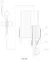
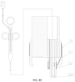
- FIG. 6A , FIG. 6B , and FIG. 6C show three manners of guiding out a current via an endoscope.
- a fourth electrically conductive part 55 is provided inside the endoscope, and the fourth electrically conductive part 55 is electrically connected to the first electrically conductive part 51.
- the fourth electrically conductive part 55 is provided on an inner wall of the instrument passage 403 of the endoscope.
- the first electrically conductive part 51 is provided on a periphery of the camera 402 at the distal end of the endoscope body 401, and is electrically connected to the fourth electrically conductive part 55 in the instrument passage 403 directly or through the sliding contact part 53.
- the fourth electrically conductive part 55 is provided on an outer wall of the endoscope body 401 of the endoscope, and the fourth electrically conductive part 55 and the first electrically conductive part 51 are integrally provided on a periphery of the endoscope body 401 to form a whole.
- the fourth electrically conductive part 55 is provided on the inner wall of the instrument passage 403 of the endoscope.
- the first electrically conductive part 51 is provided on the periphery of the camera 402 at the distal end of the endoscope body 401, and the sliding contact part 53 passes through a side wall of the endoscope body 401 to electrically connect the first electrically conductive part 51 to the fourth electrically conductive part 55 in the instrument passage 403.
- Embodiment 3 protects an expandable frame for another endoscope.
- a conductive material is provided on the peripheral surface of the expandable frame 42, and the conductive material forms the first electrically conductive part 51.
- a proximal end of the first electrically conductive part 51 is electrically connected to the fourth electrically conductive part 55.
- the fourth electrically conductive part 55 (which may be a conductor wire) is arranged along the endoscope body 401, is guided out from a proximal end of the endoscope body 401, and is electrically connected to the passive electrode 61.
- the expandable frame 42 is installed on an ordinary endoscope, so that the expandable frame 42 is tightly attached to human body tissue.
- An existing monopolar instrument is inserted in the instrument passage 403 at the same time.
- a power supply is turned on after a focus is reached, and a working circuit is formed among an electrical treatment part of the monopolar instrument, tissue to be treated, and the first electrically conductive part 51, so as to complete surgical operations.
- Embodiment 3 and Embodiment 1 lie in that the fourth conductive body instead of the sliding contact part is provided on the expandable frame, and the fourth conductive body is passed through the endoscope or provided outside the endoscope.
- the fourth conductive body is a conductor wire, and the conductor wire is passed through the endoscope or provided outside the endoscope.
- the remaining shape of the expandable frame may be consistent with that in Embodiment 1.
- Such an expandable frame is conveniently used.
- the first electrically conductive part of the expandable frame is provided on a periphery of the expandable frame and contacts a human body and guides out a current in the human body.
- the fourth electrically conductive part guides out the current in the human body, so as to provide a passage for guiding out the current from the human body.
- the fourth electrically conductive part may be easily installed inside the endoscope in a sleeving manner, it is not necessary to make additional changes to the endoscope, thereby achieving high compatibility and a wide use range.
- the electric snare 221 is replaced with an ESD knife 222 having a head part extending in an axial direction of the operating wire.
- the head part 2221 may be a needle knife or may be a T-shaped knife, a star-shaped knife, provided that the head part is applicable to ESD surgery.
- FIG. 8A to FIG. 8F show several shapes of the electrical treatment part.
- the structural parts other than the ESD knife 222 are the same as those in the foregoing embodiments, and the details of these parts are omitted herein.
- the electric snare 221 is replaced with the electrocoagulation forceps 223 having a pair of holding parts that can be opened or closed and can incise living tissue.
- the structural parts other than the electrocoagulation forceps 223 are the same as those in the foregoing embodiments, and the details of these parts are omitted herein.
- the electric snare 221 is replaced with the electric biopsy forceps 224.
- the structural parts other than the electric biopsy forceps 224 are the same as those in the foregoing embodiments, and the details of these parts are omitted herein.
- the electric snare 221 is replaced with a cutting wire 2252 having a papilla sphincterotome with a function of incising papillary sphincters.
- the papilla sphincterotome includes a conductor cavity 2251 extending longitudinally in the sheath 10 along the sheath 10.
- the conductor cavity 2251 is equivalent to the first cavity 11 in the embodiment of the electric snare 221.
- the cutting wire 2252 is accommodated in the conductor cavity.
- the cutting wire 2252 is passed through an anchor 2253 at a distance L from a distal end of the sheath and is joined to the distal end of the sheath, so that the cutting wire 2252 and the distal end form a bow-shaped cutting part 21.
- the cutting wire 2252 is securely joined to the sheath 10 at the anchor.
- a proximal end of the cutting wire 2252 is electrically connected to the operating wire 20 having conductive performance.
- the sliding contact part 53 may further include a fifth electrically conductive part 531 and a sixth electrically conductive part 532.
- the fifth electrically conductive part 531 may ensure a stable connection between the sliding contact part and the second electrode.
- the sixth electrically conductive part 532 is configured to be electrically connected to the first electrically conductive part 51.
- the fifth electrically conductive part is a steel spring ball. A highest point of the steel spring ball protrudes from an extension line of the instrument passage of the endoscope, and a tail of the steel spring ball is inserted in the expandable frame.
- the fifth electrically conductive part is electrically connected to the first electrically conductive part 51 through the sixth electrically conductive part.
- the fifth electrically conductive part 531 may be provided as an electrically conductive ring.
- a central line of the electrically conductive ring is consistent with a central axis of the instrument passage of the endoscope, and an inner diameter of the electrically conductive ring is consistent with an inner diameter of the instrument passage.
- the sixth electrically conductive part 532 is electrically connected to the first electrically conductive part 51 and the electrically conductive ring.
- the electrically conductive ring is used to keep stable contact of the electrically conductive parts in all directions and further reduce manufacturing costs.
- the fifth electrically conductive part may also be an electrically conductive prism.
- a central line of the electrically conductive prism is consistent with a longitudinal axis of the endoscope, and the electrically conductive prism protrudes from an axial extension line of a wall of the instrument passage of the endoscope.
- the fifth electrically conductive part may be an insertion tube inserted at a distal end of the instrument passage, and may ensure stable matching between the sliding contact part and the instrument passage.
- first electrically conductive part 51 may also be arranged in another manner.
- the first electrically conductive part 51 is provided in the middle of the endoscope body 401 of the endoscope.
- the return conductor 54 is provided longitudinally along the endoscope body 401, and is electrically connected to the first electrically conductive part 51.
- the feeding power supply 60 includes the passive electrode 61 and the active electrode 62.
- the passive electrode 61 is electrically connected to the third electrically conductive part 54 (or the fourth electrically conductive part 55), and is guided out at the proximal end of the endoscope body 401.
- the active electrode 62 is electrically connected to a high-frequency treatment part, and is guided out from the drive part 30.
- the third electrically conductive part 54 (or the fourth electrically conductive part 55) is provided inside the endoscope body 401 in this embodiment, a specific position of arranging the third electrically conductive part 54 is not limited, provided that the third electrically conductive part 54 (or the fourth electrically conductive part 55) can be electrically connected to the first electrically conductive part.
- the third electrically conductive part 54 (or the fourth electrically conductive part 55) may be arranged on the sheath 10, and is electrically connected to the first electrically conductive part 51 through a conduction mechanism provided on an inner side of the first electrically conductive part 51. In this case, the passive electrode 61 and the active electrode 62 are both guided out from the drive part 30.
- FIG. 16, FIG. 17 , and FIG. 6B show an endoscope.
- a first electrically conductive part 51 of the endoscope covers an outer surface of the endoscope body 401.
- the return conductor 54 is electrically connected to the proximal end of the first electrically conductive part 51, and is guided out from the proximal end of the endoscope body 401 to the passive electrode 62.
- the active electrode 61 is electrically connected to the high-frequency treatment part, and is guided out from the drive part 30.
- FIG. 18, FIG. 19 , and FIG. 6A show another endoscope.
- the first electrically conductive part 51 of endoscope covers a peripheral surface at the distal end of the camera 401.
- the return conductor 54 is arranged on an inner wall of the instrument passage 403 and is electrically connected to the passive electrode 61, and the return conductor 54 and the active electrode 62 are then guided out together from the drive part 30.
- FIG. 20 and FIG. 21 show another endoscope.
- the return conductor 54 of the endoscope is a conductor wire arranged on an outer side of the endoscope body 401, and during use, the return conductor 54 coordinate with a high-frequency treatment apparatus having the first electrically conductive part 51.
- the conductor wire is electrically connected to the first electrically conductive part 51.
- a space of contact between an outer side of the endoscope body of the endoscope and tissue is fully used to increase a conductive area of a contact part between the treatment apparatus for an endoscope and tissue in a return path, so that while the risk of bipolar instrument burns is reduced, a thermal effect between the high-frequency treatment part and tissue to be excised and electrocoagulated is further improved, thereby improving the security and operation efficiency of endoscopic surgery, and ensuring further clinical popularization and application of bipolar instruments.
Landscapes
- Health & Medical Sciences (AREA)
- Life Sciences & Earth Sciences (AREA)
- Surgery (AREA)
- Engineering & Computer Science (AREA)
- Animal Behavior & Ethology (AREA)
- General Health & Medical Sciences (AREA)
- Nuclear Medicine, Radiotherapy & Molecular Imaging (AREA)
- Veterinary Medicine (AREA)
- Biomedical Technology (AREA)
- Heart & Thoracic Surgery (AREA)
- Medical Informatics (AREA)
- Molecular Biology (AREA)
- Public Health (AREA)
- Physics & Mathematics (AREA)
- Otolaryngology (AREA)
- Plasma & Fusion (AREA)
- Pathology (AREA)
- Cardiology (AREA)
- Oral & Maxillofacial Surgery (AREA)
- Biophysics (AREA)
- Optics & Photonics (AREA)
- Radiology & Medical Imaging (AREA)
- Surgical Instruments (AREA)
- Endoscopes (AREA)
Description
- The present invention belongs to the field of medical instruments, and specifically, to a treatment apparatus for an endoscope. In particular, the present invention relates to a treatment apparatus for an endoscope of the generic type as defined in
claim 1. - Document
US 2014/0188109 A1 discloses a treatment apparatus of the generic type defined above. Specifically, this document discloses a bipolar sphincterotome including an elongate tubular member, a cutting wire, and a return path. The return path includes a conductive ink portion disposed on an outer surface at a distal portion of the tubular member. The return path also includes a return wire disposed within the tubular member that is electrically coupled to the conductive ink portion. The return wire is disposed within a lumen configured to have two or more functions, one of which being to house the return wire. Additionally, the conductive ink portion is circumferentially disposed on the outer surface to provide visual access to a wire guide lumen. - Document
US 2003/0181900 A1 discloses an endoscopic tissue ablation system including a plurality of electrode pairs and a viewing window between each pair of adjacent electrodes. The electrodes can be energized in a predetermined sequence to ablate tissue around the circumference of a body lumen. - There are so far known bipolar treatment instruments for an endoscope that are passed through endoscopes to treat living tissue and the like. Some of the bipolar treatment instruments for an endoscope have, for example, a function of supplying a high-frequency current to a treatment instrument to perform treatments such as incision, cauterization, and hemostasis on living tissue.
- As an example of such a treatment instrument for an endoscope, a high-frequency incision instrument that uses a polypectomy snare supplied with a high-frequency current to incise living tissue is recorded in document
CN 102 413 786 B . An electric wire, a passive electrode arranged on a periphery of an extending part, living tissue in contact with the passive electrode, the polypectomy snare, and an operating wire are connected to a feeding electrode to form a current loop to excise a polyp. In addition, a bipolar sphincterotome is recorded in documentCN 205 697 995 U and includes a control part, an insulating sheath, and a cutting part. A distal end of the control part is connected to a proximal end of the insulating sheath. The cutting part includes a cutting electrode, a passive electrode, a cutting electrode wiring terminal that may be connected to the cutting electrode, a passive electrode wiring terminal that may be connected to the passive electrode, a cutting electrode conductor connecting the cutting electrode and the cutting electrode wiring terminal, and a passive electrode conductor connecting the passive electrode and the passive electrode wiring terminal. The cutting electrode and the passive electrode are provided on a distal end of the insulating sheath and are respectively connected to the control part through the cutting electrode conductor and the passive electrode conductor. - However, both the foregoing technical solutions can be improved. First, an active electrode (that is, the foregoing high-frequency treatment part and cutting part) does not have an obvious thermal effect, and a cutting speed is relatively slow, resulting in limited clinical application. Second, an area of contact between a passive electrode and tissue is relatively small, and tissue may be burned accidentally. Third, in both the solutions, the passive electrode and the active electrode are relatively close, the two electrodes may contact or a current may flow through tissue fluids between the electrodes to cause a short circuit failure. Fourth, in a surgical instrument for an endoscope, treatment instruments such as electrocoagulation forceps, biopsy forceps, needle knives, and the like in addition to snares and papilla incision knives need to be electrified to perform incision, cauterization, hemostasis, among other work. The passive electrode in the foregoing technical solution has relatively low adaptability.
- Based on this, to overcome the disadvantages in the prior art, the present invention provides a treatment apparatus for an endoscope as defined in
claim 1 attached. Preferred embodiments of the invention are defined in claims dependent uponclaim 1 attached. The structural design is appropriate, the cutting speed is relatively high, the risk of passive electrode burns is relatively low, and adaptability is provided. - The beneficial effects of the present invention are as follows:
The first electrode performs an electrical operation on a human body, and a current that enters the human body is looped through the second electrically conductive part instead of flowing all over the human body, so as to avoid damage to other organs or electronic apparatuses (for example, a pacemaker) in the human body, thereby ensuring the safety of the entire operation. Provided that electrical requirements can be satisfied, the second electrode may be provided at any position in the endoscope, so that a sufficiently large area of contact between the second electrically conductive part and the human body is ensured to fully guide out a current. A space of contact between an outer side of the endoscope body of the endoscope and tissue is fully used to increase a conductive area of a contact part through which a current is guided out from human body tissue in a return path, so that while the risk of burns is reduced, a thermal effect is further improved, thereby improving the security and operation efficiency of endoscopic surgery, and ensuring further clinical popularization and application of the treatment apparatus for an endoscope. -
-
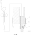
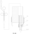
FIG. 1A is a schematic diagram of coordination between a treatment apparatus for an endoscope according toEmbodiment 1 of the present invention and an endoscope; -
FIG. 1B is a schematic diagram of coordination between a treatment apparatus for an endoscope according toEmbodiment 1 of the present invention and an endoscope; -
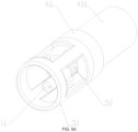
FIG. 2 is a schematic diagram of an expandable frame installed in a treatment apparatus for an endoscope according toEmbodiment 1 of the present invention; -
FIG. 3 is a schematic diagram of an end surface inFIG. 2 ; -
FIG. 4 is a diagram showing several arrangement manners of a second conductive body according toEmbodiment 1 of the present invention; -
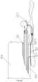
FIG. 5A to FIG. 5C are schematic diagrams of other implementations of the expandable frame according toEmbodiment 1 of the present invention and an endoscope; -
FIG. 6A to FIG. 6C are schematic diagrams of coordination between a treatment apparatus for an endoscope according to Embodiment 2 of the present invention and an endoscope; -
FIG. 7 to FIG. 13 are schematic diagrams according to another implementation of the present invention; -
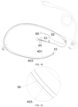
FIG. 14 is a schematic diagram according to another implementation of the present invention; -
FIG. 15 is an enlarged view of A inFIG. 14 ; -
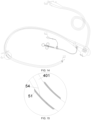
FIG. 16 is a schematic diagram according to another implementation of the present invention; -
FIG. 17 is an enlarged view of B inFIG. 16 ; -
FIG. 18 is a schematic diagram according to another implementation of the present invention; -
FIG. 19 is an enlarged view of C inFIG. 18 ; -
FIG. 18 is a schematic diagram according to another implementation of the present invention; -
FIG. 19 is an enlarged view of C inFIG. 18 ; -
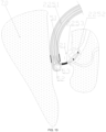
FIG. 20 is a schematic diagram according to another implementation of the present invention; -
FIG. 21 is an enlarged view of E inFIG. 20 ; -
FIG. 22 is a schematic diagram according to Embodiment 3 of the present invention; -
FIG. 23 is a partial enlarged view ofFIG. 22 ; -
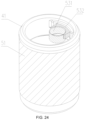
FIG. 24 is a schematic diagram according to another implementation of the present invention; -
FIG. 25 is a partial sectional view ofFIG. 24 ; -
FIG. 26 is a schematic diagram of an overall structure of the implementation inFIG. 24 . - Sheath 10,
first cavity 11,second cavity 12,operating wire 20, cutting part 21,ESD knife 222,electric snare 221,electrocoagulation forceps 223,electric biopsy forceps 224,conductor cavity 2251,cutting wire 2252, anchor 2253,drive part 30, slidingring 31,endoscope body 401,instrument passage 403,transparent cover 41,expandable frame 42,return path 50, first electricallyconductive part 51, second electricallyconductive part 52, slidingcontact part 53, third electricallyconductive part 54, fourth electricallyconductive part 55,feeding electrode 60,passive electrode 61,active electrode 62,tissue operation mechanism 70. - The present invention is further described below in detail, but the implementations of the present invention are not limited thereto.
- As shown in
FIG. 1A to FIG. 3 , a treatment apparatus for an endoscope includes: a first electrode, including an electrical treatment part and anoperating wire 20; a second electrode, configured to be provided inside the endoscope (not shown), and including a first electricallyconductive part 51 and a slidingcontact part 53 electrically connected to the first electricallyconductive part 51, the first electricallyconductive part 51 being configured to contact a human body; and asheath 10, provided on a surface thereof with a second electricallyconductive part 52, where theoperating wire 20 is passed through thesheath 10, thesheath 10 is passed through the endoscope, and thesheath 10 is movable back and forth in an instrument passage of the endoscope. Specifically, thesheath 10 of the present invention is passed through theinstrument passage 403 of the endoscope and is controlled by a drive part 30 (a slidingring 31 is provided on the drive part 30) connected outside a body to move freely forward or backward in theinstrument passage 403. - As shown in
FIG. 2 , afirst cavity 11 extending in an axial direction and having openings at two ends is formed in thesheath 10. Thesheath 10 is made of an insulating material, for example, insulating resin. In addition, preferably, thesheath 10 needs to be flexible enough to bend and move forward or backward along lumen tissue and the like in an organism. - As shown in
FIG. 1A ,FIG. 1B , andFIG. 4 , thefirst cavity 11 and asecond cavity 12 are formed in thesheath 10. Theconductive operating wire 20 is passed through thefirst cavity 11 in a manner of moving freely forward or backward. The electrical treatment part (including, but is not limited to, an endoscopic submucosal dissection (ESD)knife 222, anelectric snare 221,electrocoagulation forceps 223,electric biopsy forceps 224, and a papilla sphincterotomy hereinafter) is provided at a distal end of theoperating wire 20, and in this embodiment, is an electric snare. Theoperating wire 20 is conductive. A proximal end of theoperating wire 20 is electrically connected to anactive electrode 62 of a feeding electrode 60 (in the present invention, the feedingelectrode 60 includes apassive electrode 61 and theactive electrode 62, referring toFIG. 14 for details). Although theoperating wire 20 is conductive (or even theoperating wire 20 and the electrical treatment part may be one overall conductor) in this embodiment, the specific material and performance of theoperating wire 20 are not limited, provided that the electrical treatment part can be manipulated to move forward or backward. Alternatively, theoperating wire 20 may be not conductive, and a conductor wire is additionally used between the electrical treatment part and an electrode to establish a conductive connection. - An expandable frame is sleeved over a front end of the endoscope. As shown in
FIG. 2 and FIG. 3 . Theexpandable frame 42 includes asleeve 411 sleeved over the endoscope and atransparent cover 41. Thetransparent cover 41 is made of a transparent insulating material. Thetransparent cover 41 may block a part of the view of a camera 402 (as shown inFIG. 1 andFIG. 2 ) of the endoscope, and the endoscope may obtain an image through thetransparent cover 41. The first electricallyconductive part 51 is provided on a periphery of the expandable frame. A diameter of a peripheral surface of the expandable frame is greater than a diameter of a peripheral surface of the endoscope. The slidingcontact part 53 may be provided on the expandable frame. -
FIG. 5A ,FIG. 5B , andFIG. 5C further show other implementations in which theexpandable frame 42 is installed on the treatment apparatus for an endoscope. During use, theexpandable frame 42 is assembled at a distal end of anendoscope body 401 of the endoscope, the first electricallyconductive part 51 is provided on a periphery of the expandable frame, and the first electricallyconductive part 51 has a relatively large surface area to fully contact human body tissue. Preferably, a structure of the first electricallyconductive part 51 may be as follows: A conductive material is provided on a peripheral surface of theendoscope 42, and the conductive material forms the first electricallyconductive part 51. The type of the conductive material may be selected as required. In addition, preferably, the slidingcontact part 53 is provided on theexpandable frame 42 and has conductive performance. A part of the slidingcontact part 53 is electrically connected to the first electricallyconductive part 51, and another part of the slidingcontact part 53 forms tight fit with a periphery of the sheath and is electrically connected to the second electricallyconductive part 52. - It should be noted that although the
expandable frame 42 with atransparent cap 41 is provided in the foregoing embodiment, the foregoing two structures are not limited, provided that is an auxiliary apparatus for an endoscope can be tightly attached to a side wall of tissue and has a larger surface area than the sheath, so that the first electricallyconductive part 51 may be attached to the peripheral surface of the peripheral surface of theexpandable frame 42 and is connected to the second electricallyconductive part 52 through the slidingcontact part 53 to achieve the same effect. Preferably, as shown inFIG. 7A , theexpandable frame 42 includes a sleeve 411' and a flexible part or anelastic part 412 connected to the sleeve 411', the sleeve 411' is configured to be sleeved over the endoscope, and the slidingcontact part 53 is fixed on an inner side of the expandable frame or an inner side of the sleeve 411'. The flexible part orelastic part 412 provides particular cushioning for the slidingcontact part 53 or applies particular pressure to keep electrical contact between the slidingcontact part 53 and the second electricallyconductive part 52, so that the slidingcontact part 53 is kept being configured to be electrically connected to the second electricallyconductive part 52. - Further, as shown in
FIG. 2 and FIG. 3 , the second electricallyconductive part 52 is fixed at a position, at a distance of L1 near a top end, on a periphery of a front section of thesheath 10, and is conductive. An outer diameter of the second electricallyconductive part 52 does not exceed an inner diameter of theinstrument passage 403. Moreover, referring to bothFIG. 1B andFIG. 4 , thesecond cavity 12 is formed in thesheath 10. A third electricallyconductive part 54 having a conductive function is encapsulated in thesecond cavity 12. The second electricallyconductive part 52 is electrically connected to the third electricallyconductive part 54, and the second electricallyconductive part 52 is electrically connected to apassive electrode 61 of the feedingelectrode 60 through the third electricallyconductive part 54, and an external power supply supplies power to the electric snare. The present invention is not limited thereto. Alternatively, a layer of a conductive material is provided on an outer surface of thesheath 10, and the conductive material forms the second electricallyconductive part 52. The type of the conductive material may be selected as required. The layer of the conductive material at least covers a peripheral surface of a part of thesheath 10. The layer of the conductive material may be made very thin to reduce an increase in an additional volume. Preferably, the layer of the conductive material is made smooth to facilitate the movement of thesheath 10 in the instrument passage of the endoscope. - Although the third electrically
conductive part 54 is encapsulated in thesheath 12 in this embodiment, a specific position of the third electricallyconductive part 54 on the sheath is not limited, provided that the third electricallyconductive part 54 is electrically isolated from theelectric snare 221 in thefirst cavity 11 and is eventually electrically connected to the first electricallyconductive part 51.FIG. 4 shows several arrangement manners of the third electricallyconductive part 54 in thesheath 12. - Although the third electrically
conductive part 54 has a linear shape in this embodiment, the specific shape and structure of the third electricallyconductive part 54 are not limited, provided that the third electricallyconductive part 54 can electrically connect the first electricallyconductive part 51 to the feeding electrode and can bend in accordance with a flexible cavity. - A working manner of the present invention is described below. Before operations of endoscopic surgery are started, the
expandable frame 42 with the first electricallyconductive part 51 is assembled at a distal end of anendoscope body 401 of the endoscope, and thesheath 10 with theelectric snare 221 is further inserted in theinstrument passage 403 of the endoscope. Next, the endoscope is inserted in a cavity (for example, a digestive tract, a vagina) of a human body, and an image transmitted by thecamera 402 is simultaneously observed. When a focus is reached, a slidingring 31 on thedrive part 30 is operated, theelectric snare 221 is closed around tissue to be excised, and the first electricallyconductive part 51 is tightly attached totissue 70 on a side wall at the same time. Finally, the feedingelectrode 60 is turned on, and a current flows through theactive electrode 62 of the feedingelectrode 60, theelectric snare 221, the tissue to be excised, and a return path 50 (as shown inFIG. 12 , thereturn path 50 includes the first electricallyconductive part 51, the slidingcontact part 53, the second electricallyconductive part 52, and the third electrically conductive part 54), and returns to thepassive electrode 61 of the feedingelectrode 60 to form a loop. High heat is generated at a contact position between theelectric snare 221 and the tissue to be excised to excise the tissue. For the formation of thereturn path 50, and when thesheath 10 is located in a preset position, the slidingcontact part 53 contacts and is electrically connected to the second electricallyconductive part 52 and thesheath 10 is in sliding fit with the slidingcontact part 53. The preset position is not necessarily a point, and it may be designed that when thesheath 10 slides within a particular range, the slidingcontact part 53 can contact and be electrically connected to the second electricallyconductive part 52. In this way, the first electricallyconductive part 51, the slidingcontact part 53, the second electricallyconductive part 52, and the third electricallyconductive part 54 form thereturn path 50 of the current guided out from the human body. In a conventional instrument for an endoscope, thereturn path 50 is not provided or no other manner is used to guide out a current, and a reliable electrical connection to the human body cannot be kept as well as in the present invention, easily resulting in accidental injury. Because the first electricallyconductive part 51 is close to the electrical treatment part, a current that enters the human body is guided out by the first electricallyconductive part 51 instead of flowing all over the human body. Therefore, a stronger current can be used, so as to obtain electrothermal efficiency that cannot be obtained by a conventionalelectric snare 221, and the stronger current generates more heat at the focus. The description of theactive electrode 62 and thepassive electrodes 61 herein and in the context is only used for ease of recognizing a current direction in a same loop, and an actual flowing direction of a current is not limited. A high-frequency alternating current with a frequency not less than 20 KHZ usually flows in the formed loop. - It should be noted that the foregoing electrical contact and electrical connection means that a current can be in practice conducted. For such contact, two entities may contact or the entities may not contact (there is a gap) but complete conduction of a current by means of conductive liquids (for example, tissue fluids, and secretions) in a human body.
- The preferred solutions and beneficial effects of this embodiment are as follows:
- 1. The treatment apparatus for the endoscope includes: the first electrode, including the electrical treatment part and the
operating wire 20, where the electrical treatment part is configured to perform an electrical operation on a human body, and the electrical operation includes, but is not limited to, an electric shock effect, an electric heating effect, and an electrical cauterization effect; the second electrode, configured to be installed inside the endoscope, and including the first electricallyconductive part 51 and the slidingcontact part 53 electrically connected to the first electricallyconductive part 51, and the first electricallyconductive part 51 being configured to contact a human body; and thesheath 10, the second electricallyconductive part 52 being provided on the surface of thesheath 10, where theoperating wire 20 is passed through thesheath 10, thesheath 10 is passed through the endoscope, thesheath 10 is movable back and forth in the instrument passage of the endoscope, and when thesheath 10 is located in a preset position, the slidingcontact part 53 contacts and is electrically connected to the second electricallyconductive part 52 and thesheath 10 is in sliding fit with the slidingcontact part 53.
The first electrode performs an electrical operation on a human body, and a current that enters the human body is looped through the second electrically conductive part instead of flowing all over the human body, so as to avoid damage to other organs or electronic apparatuses (for example, a pacemaker) in the human body, thereby ensuring the safety of the entire operation. Provided that electrical requirements can be satisfied, the second electrode may be provided at any position in the endoscope, so that a sufficiently large area of contact between the second electricallyconductive part 52 and the human body is ensured to fully guide out a current. - 2. The treatment apparatus for the endoscope further includes the
expandable frame 42. Theexpandable frame 42 is configured to be sleeved over the endoscope. The first electricallyconductive part 51 is provided on a periphery of theexpandable frame 42. A distance between a part, being configured to contact a human body, of the first electricallyconductive part 51 and an axis of the endoscope is greater than a radius of the endoscope. Theexpandable frame 42 is used to increase the distance between the part, being configured to contact the human body, of the first electricallyconductive part 51 and the axis of the endoscope. Because thesheath 10 is passed through the endoscope, the first electricallyconductive part 51 contacts the human body first, thereby ensuring reliable contact between the first electricallyconductive part 51 and the human body and avoiding electrical leakage.
Provided that electrical requirements can be satisfied, theexpandable frame 42 may be provided at any position of the endoscope. Preferably, the expandable frame is provided at a distal end of the endoscope, and the expandable frame is kept as close as possible to the electrical treatment part of the first electrode, thereby reducing a path of a current flowing through the human body. - 3. A conductive material is provided on the peripheral surface of the
expandable frame 42, and the conductive material forms the first electricallyconductive part 51. The type of the conductive material may be selected as required. The layer of the conductive material at least covers a peripheral surface of a part of theexpandable frame 42. The layer of the conductive material may be made very thin to reduce an increase in an additional volume. Preferably, the layer of the conductive material is made smooth to reduce damage to the human body. In this embodiment, the expandable frame has a cylindrical shape, but is not limited thereto. Another shape may be used, provided that the expandable frame can be installed inside the endoscope. - 4. The
expandable frame 42 includes a sleeve and a transparent cover connected to the sleeve. The sleeve is configured to be sleeved over the endoscope. The transparent cover is transparent or translucent. The transparent cover is configured to allow the endoscope to obtain an image. When a part, blocking an optical device (including, but is not limited to, a camera, a lighting device) of the endoscope, of the cover of theexpandable frame 42 is made transparent or translucent, it is ensured that the optical device acquires an image normally. - 5. The
expandable frame 42 includes a sleeve and a flexible part or an elastic part connected to the sleeve, the sleeve is configured to be sleeved over the endoscope, and the slidingcontact part 53 is fixed on an inner side of the expandable frame, and is connected to the flexible part or elastic part; or the slidingcontact part 53 may be fixed on an inner side of the sleeve. The flexible part or elastic part provides particular cushioning for the slidingcontact part 53, so that the slidingcontact part 53 is kept being electrically connected to the second electricallyconductive part 52. - 6. It may be selected as required that the electrical treatment part is the
electric snare 221 or theelectrocoagulation forceps 223 or theelectric biopsy forceps 224 or a sphincterotome. The treatment apparatus for the endoscope of the present invention has a wide applicable range. - 7. A layer of a conductive material is provided on an outer surface of the
sheath 10, and the conductive material forms the second electricallyconductive part 52. The type of the conductive material may be selected as required. The layer of the conductive material at least covers a peripheral surface of a part of thesheath 10. The layer of the conductive material may be made very thin to reduce an increase in an additional volume. Preferably, the layer of the conductive material is made smooth to facilitate the movement of thesheath 10 in the instrument passage of the endoscope. - 8. The
first cavity 11 and thesecond cavity 12 are provided on thesheath 10. Theoperating wire 20 is passed through thefirst cavity 11. The third electricallyconductive part 54 is provided in thesecond cavity 12. The third electricallyconductive part 54 is arranged in an axial direction along the sheath, and the third electricallyconductive part 54 is electrically connected to the second electricallyconductive part 52. Thesecond cavity 12 is provided for special use by the third electricallyconductive part 54, thereby ensuring that the third electricallyconductive part 54 is electrically insulated from the second electricallyconductive part 52 and the first electrode, thereby improving reliability. - 9. The
second cavity 12 has an annular shape surrounding thefirst cavity 11. The third conductive layer is distributed around thefirst cavity 11, so that an increase in the radius of thesheath 10 caused by the third electricallyconductive part 54 may be restrained, so as to reduce the radius of thesheath 10. - 10. The treatment apparatus for the endoscope further includes the feeding
electrode 60. The feedingelectrode 60 includes theactive electrode 62 and thepassive electrode 61. The electrical treatment part is electrically connected to theactive electrode 62. The third electricallyconductive part 54 is electrically connected to thepassive electrode 61. Theactive electrode 62 supplies power to the electrical treatment part. The electrical treatment part performs an electrical operation on a human body. A current enters the human body from the electrical treatment part, is then guided out from the first electricallyconductive part 51, and flows through the second electricallyconductive part 52 to return to thepassive electrode 61, so that the current flows by a minimum path in the human body. - 11. The second electrically
conductive part 52 surrounds thesheath 10 by one loop in a circumferential direction of thesheath 10, so that when thesheath 10 slides back and forth in the endoscope, desirable contact is kept between the second electricallyconductive part 52 and the slidingcontact part 53, and electrical contact is not affected even if thesheath 10 spins. - In this embodiment, the first electrically
conductive part 51 is provided on theexpandable frame 42 of the endoscope. An outer diameter of theexpandable frame 42 is greater than an outer diameter of theendoscope body 401 of the endoscope, and the outer diameter of theendoscope body 401 of the endoscope is greater than an outer diameter of thesheath 10. Therefore, compared with the case in which the first electricallyconductive part 51 is provided on thesheath 10, when the first electricallyconductive part 51 is provided on theexpandable frame 42, the first electricallyconductive part 51 contacts a human body more easily to form an electrical loop, so as to ensure that "the electrical treatment part, the human body tissue, and the first electrically conductive part" form a stable current loop during surgery, thereby preventing the human body from burns. - Because the outer diameter of the
expandable frame 42 > the outer diameter of theendoscope body 401 of the endoscope > the outer diameter of thesheath 10, an area of contact between the first electricallyconductive part 51 and the human body is large, a stronger surgical current may be used, and the surgery time is shortened. During surgery when a current is maintained within a safe current range, a length of safe contact of the first electrically conductive part 51 (the first electricallyconductive part 51 provided inside the endoscope body 401) provided on theexpandable frame 42 is far less than a length of the first electricallyconductive part 41 provided on the sheath 10:
To facilitate description, for example, a diameter of a cutting head is 0.4 mm, an electrical cutting current is 680 mA, and an average surgery time is 2.1 s. According to the regulations inGB9706.4-2009 - To describe a relationship between an arrangement position of a contact electrode and a requirement of a safe contact length L, it is assumed that a common digestive endoscope with a relatively small size, that is, a duodenoscope, is chosen for measurement. An outer diameter of the duodenoscope is d 1 = 1.25cm, and a maximum outer diameter of the treatment apparatus does not exceed an inner diameter of an endoscope channel d 2 = 0.32cm. (1) The first electrically
conductive part 51 is provided on thesheath 10. - It is assumed that when the first electrically
conductive part 51 is provided on the sheath 10 (that is, the first electricallyconductive part 51 is provided on the peripheral surface of thesheath 10 and has an annular shape), an area of contact between the first electricallyconductive part 51 and a human body is:
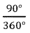
conductive part 51 has an annular shape surrounding the peripheral surface of thesheath 10 by one loop, a range of contact between the first electricallyconductive part 51 and the human body tissue is 1/4 of the arc surface (that is, only 90° of the circumferential 360° contacts human body tissue). - To satisfy the safe threshold of the contact current for the human body:

- Therefore, assuming that the first electrically
conductive part 51 is provided on thesheath 10, to satisfy the safe threshold of the contact current for the human body, a length of the first electricallyconductive body 51 in an axial direction of the sheath needs to be greater than 5.68 cm, or otherwise a deep burn may occur in the human body during normal surgery. (2) The first electricallyconductive part 51 is provided inside theendoscope body 401. - Assuming that the first electrically
conductive part 51 is provided inside theendoscope body 401, a maximum area of contact with human body tissue is:
- To satisfy the safe threshold of the contact current for the human body:

- As may be seen from above, the required length of the first electrically conductive part in the safe range is L1 » L 2. When the first electrically conductive part is provided on the peripheral surface of the expandable frame, the safe contact length required to prevent a deep burn is shorter than the length of the first electrically conductive part provided on the peripheral surface of the sheath by approximately 75%, so that the safe contact length can be reached more easily for the contact electrode during surgery, and the surgery is safer and more effective.
- Embodiment 2 protects an endoscope.
FIG. 6A ,FIG. 6B , andFIG. 6C show three manners of guiding out a current via an endoscope. A fourth electricallyconductive part 55 is provided inside the endoscope, and the fourth electricallyconductive part 55 is electrically connected to the first electricallyconductive part 51. - In a first implementation, the fourth electrically
conductive part 55 is provided on an inner wall of theinstrument passage 403 of the endoscope. The first electricallyconductive part 51 is provided on a periphery of thecamera 402 at the distal end of theendoscope body 401, and is electrically connected to the fourth electricallyconductive part 55 in theinstrument passage 403 directly or through the slidingcontact part 53. - In a second implementation, the fourth electrically
conductive part 55 is provided on an outer wall of theendoscope body 401 of the endoscope, and the fourth electricallyconductive part 55 and the first electricallyconductive part 51 are integrally provided on a periphery of theendoscope body 401 to form a whole. - In a third implementation, the fourth electrically
conductive part 55 is provided on the inner wall of theinstrument passage 403 of the endoscope. The first electricallyconductive part 51 is provided on the periphery of thecamera 402 at the distal end of theendoscope body 401, and the slidingcontact part 53 passes through a side wall of theendoscope body 401 to electrically connect the first electricallyconductive part 51 to the fourth electricallyconductive part 55 in theinstrument passage 403. - Preferred solutions and beneficial effects of this embodiment are as follows:
- 1. The endoscope includes the first electrically
conductive part 51 provided on the outer surface of the endoscope. The first electricallyconductive part 51 is configured to contact a human body. An instrument passage is provided in the endoscope. The instrument passage is configured to be passed through by a treatment apparatus for an endoscope. The fourth electricallyconductive part 55 is provided inside the endoscope. The first electricallyconductive part 51 is electrically connected to the fourth electricallyconductive part 55. The first electricallyconductive part 51 and the fourth electricallyconductive part 55 provide the endoscope with an electrical path for guiding out a current in a human body. The current that enters the human body is guided out by the first electricallyconductive part 51 and then guided out by the fourth electricallyconductive part 55 in the endoscope.
Preferably, the second electricallyconductive part 52 is configured to be electrically connected to thepassive electrode 61 of the feedingelectrode 60. - 2. The first electrically
conductive part 51 is directly provided inside the endoscope, the first electricallyconductive part 51 may be embedded in an outer wall of the endoscope, or a layer of a conductive material may be provided on the peripheral surface of the endoscope, and the conductive material forms the fourth electricallyconductive part 55. - 3. A connecting through hole is formed in the endoscope. The peripheral surface of the endoscope and the instrument passage are communicated through the connecting through hole. The conductive material is provided in the connecting through hole to electrically connect to the first electrically
conductive part 51 to the fourth electricallyconductive part 55. After being guided out from the first electricallyconductive part 51, the current that enters the human body sequentially passes through the conductive material in the connecting through hole and the fourth electricallyconductive part 55 before being guided out. - 4. The conductive material is provided on an end surface at the distal end of the endoscope to electrically connect the first electrically
conductive part 51 to the fourth electricallyconductive part 55. With such an arrangement, the end surface of the endoscope is also a position for contact with the human body. The end surface and the peripheral surface of the endoscope may both guide out a current from the human body when contacting the human body, so that an area of electrical contact with the human body may be enlarged. - Embodiment 3 protects an expandable frame for another endoscope. As shown in
FIG. 22 and FIG. 23 , a conductive material is provided on the peripheral surface of theexpandable frame 42, and the conductive material forms the first electricallyconductive part 51. A proximal end of the first electricallyconductive part 51 is electrically connected to the fourth electricallyconductive part 55. The fourth electrically conductive part 55 (which may be a conductor wire) is arranged along theendoscope body 401, is guided out from a proximal end of theendoscope body 401, and is electrically connected to thepassive electrode 61. During working, theexpandable frame 42 is installed on an ordinary endoscope, so that theexpandable frame 42 is tightly attached to human body tissue. An existing monopolar instrument is inserted in theinstrument passage 403 at the same time. A power supply is turned on after a focus is reached, and a working circuit is formed among an electrical treatment part of the monopolar instrument, tissue to be treated, and the first electricallyconductive part 51, so as to complete surgical operations. - The differences between Embodiment 3 and
Embodiment 1 lie in that the fourth conductive body instead of the sliding contact part is provided on the expandable frame, and the fourth conductive body is passed through the endoscope or provided outside the endoscope. Preferably, the fourth conductive body is a conductor wire, and the conductor wire is passed through the endoscope or provided outside the endoscope. The remaining shape of the expandable frame may be consistent with that inEmbodiment 1. Such an expandable frame is conveniently used. The first electrically conductive part of the expandable frame is provided on a periphery of the expandable frame and contacts a human body and guides out a current in the human body. Next, the fourth electrically conductive part guides out the current in the human body, so as to provide a passage for guiding out the current from the human body. The fourth electrically conductive part may be easily installed inside the endoscope in a sleeving manner, it is not necessary to make additional changes to the endoscope, thereby achieving high compatibility and a wide use range. - The technical solutions in the foregoing embodiments may be implemented separately or implemented in combination, but is not limited to the foregoing embodiments. For example, the following variants may be used.
- For example, to perform ESD surgery, as shown in
FIG. 7A andFIG. 7B , theelectric snare 221 is replaced with anESD knife 222 having a head part extending in an axial direction of the operating wire. The head part 2221 may be a needle knife or may be a T-shaped knife, a star-shaped knife, provided that the head part is applicable to ESD surgery.FIG. 8A to FIG. 8F show several shapes of the electrical treatment part. The structural parts other than theESD knife 222 are the same as those in the foregoing embodiments, and the details of these parts are omitted herein. - For another example, to perform hemostasis during surgery, as shown in
FIG. 9 andFIG. 10 , theelectric snare 221 is replaced with theelectrocoagulation forceps 223 having a pair of holding parts that can be opened or closed and can incise living tissue. The structural parts other than theelectrocoagulation forceps 223 are the same as those in the foregoing embodiments, and the details of these parts are omitted herein. - For still another example, to perform biopsy and hemostasis, as shown in
FIG. 11 andFIG. 12 , theelectric snare 221 is replaced with theelectric biopsy forceps 224. The structural parts other than theelectric biopsy forceps 224 are the same as those in the foregoing embodiments, and the details of these parts are omitted herein. - For yet another example, to perform endoscopic retrograde cholangiopancreatography (ERCP), as shown in
FIG. 13 , theelectric snare 221 is replaced with acutting wire 2252 having a papilla sphincterotome with a function of incising papillary sphincters. The papilla sphincterotome includes aconductor cavity 2251 extending longitudinally in thesheath 10 along thesheath 10. Theconductor cavity 2251 is equivalent to thefirst cavity 11 in the embodiment of theelectric snare 221. Thecutting wire 2252 is accommodated in the conductor cavity. Thecutting wire 2252 is passed through an anchor 2253 at a distance L from a distal end of the sheath and is joined to the distal end of the sheath, so that thecutting wire 2252 and the distal end form a bow-shaped cutting part 21. Thecutting wire 2252 is securely joined to thesheath 10 at the anchor. A proximal end of thecutting wire 2252 is electrically connected to theoperating wire 20 having conductive performance. The remaining structural parts in this embodiment are the same as those in the foregoing embodiments, and the details of these parts are omitted herein. - In addition, preferably, as shown in
FIG. 24 to FIG. 26 , the slidingcontact part 53 may further include a fifth electricallyconductive part 531 and a sixth electricallyconductive part 532. The fifth electricallyconductive part 531 may ensure a stable connection between the sliding contact part and the second electrode. The sixth electricallyconductive part 532 is configured to be electrically connected to the first electricallyconductive part 51. InFIG. 24 to FIG. 26 , the fifth electrically conductive part is a steel spring ball. A highest point of the steel spring ball protrudes from an extension line of the instrument passage of the endoscope, and a tail of the steel spring ball is inserted in the expandable frame. The fifth electrically conductive part is electrically connected to the first electricallyconductive part 51 through the sixth electrically conductive part. In addition, there may be another implementation of the fifth electricallyconductive part 531. For example, the fifth electricallyconductive part 531 may be provided as an electrically conductive ring. A central line of the electrically conductive ring is consistent with a central axis of the instrument passage of the endoscope, and an inner diameter of the electrically conductive ring is consistent with an inner diameter of the instrument passage. In this case, the sixth electricallyconductive part 532 is electrically connected to the first electricallyconductive part 51 and the electrically conductive ring. The electrically conductive ring is used to keep stable contact of the electrically conductive parts in all directions and further reduce manufacturing costs. The fifth electrically conductive part may also be an electrically conductive prism. A central line of the electrically conductive prism is consistent with a longitudinal axis of the endoscope, and the electrically conductive prism protrudes from an axial extension line of a wall of the instrument passage of the endoscope. Alternatively, the fifth electrically conductive part may be an insertion tube inserted at a distal end of the instrument passage, and may ensure stable matching between the sliding contact part and the instrument passage. - In addition, the first electrically
conductive part 51 may also be arranged in another manner. - In a variant, as shown in
FIG. 14 and FIG. 15 , the first electricallyconductive part 51 is provided in the middle of theendoscope body 401 of the endoscope. Thereturn conductor 54 is provided longitudinally along theendoscope body 401, and is electrically connected to the first electricallyconductive part 51. The feedingpower supply 60 includes thepassive electrode 61 and theactive electrode 62. Thepassive electrode 61 is electrically connected to the third electrically conductive part 54 (or the fourth electrically conductive part 55), and is guided out at the proximal end of theendoscope body 401. In addition, theactive electrode 62 is electrically connected to a high-frequency treatment part, and is guided out from thedrive part 30. Although the third electrically conductive part 54 (or the fourth electrically conductive part 55) is provided inside theendoscope body 401 in this embodiment, a specific position of arranging the third electricallyconductive part 54 is not limited, provided that the third electrically conductive part 54 (or the fourth electrically conductive part 55) can be electrically connected to the first electrically conductive part. The third electrically conductive part 54 (or the fourth electrically conductive part 55) may be arranged on thesheath 10, and is electrically connected to the first electricallyconductive part 51 through a conduction mechanism provided on an inner side of the first electricallyconductive part 51. In this case, thepassive electrode 61 and theactive electrode 62 are both guided out from thedrive part 30. - In another variant example,
FIG. 16, FIG. 17 , andFIG. 6B show an endoscope. A first electricallyconductive part 51 of the endoscope covers an outer surface of theendoscope body 401. Thereturn conductor 54 is electrically connected to the proximal end of the first electricallyconductive part 51, and is guided out from the proximal end of theendoscope body 401 to thepassive electrode 62. Theactive electrode 61 is electrically connected to the high-frequency treatment part, and is guided out from thedrive part 30. - In another variant example,
FIG. 18, FIG. 19 , andFIG. 6A show another endoscope. The first electricallyconductive part 51 of endoscope covers a peripheral surface at the distal end of thecamera 401. Thereturn conductor 54 is arranged on an inner wall of theinstrument passage 403 and is electrically connected to thepassive electrode 61, and thereturn conductor 54 and theactive electrode 62 are then guided out together from thedrive part 30. - In another variant example,
FIG. 20 and FIG. 21 show another endoscope. Thereturn conductor 54 of the endoscope is a conductor wire arranged on an outer side of theendoscope body 401, and during use, thereturn conductor 54 coordinate with a high-frequency treatment apparatus having the first electricallyconductive part 51. The conductor wire is electrically connected to the first electricallyconductive part 51. - In the present invention, a space of contact between an outer side of the endoscope body of the endoscope and tissue is fully used to increase a conductive area of a contact part between the treatment apparatus for an endoscope and tissue in a return path, so that while the risk of bipolar instrument burns is reduced, a thermal effect between the high-frequency treatment part and tissue to be excised and electrocoagulated is further improved, thereby improving the security and operation efficiency of endoscopic surgery, and ensuring further clinical popularization and application of bipolar instruments.
- The technical features in the foregoing embodiments may be randomly combined. For simplicity of description, all possible combinations of the technical features in the foregoing embodiments are not described. However, it should be considered that these combinations of technical features fall within the scope recorded in the specification provided that these combinations of technical features do not have any conflict.
- The foregoing embodiments only describe several implementations of the present invention, and their description is specific and detailed, but cannot therefore be understood as a limitation to the patent scope of the present invention, which is defined by the appended claims.
Claims (7)
- A treatment apparatus for an endoscope, comprising:a first electrode, comprising an electrical treatment part (221, 222, 223, 224, 225) andan operating wire (20);a second electrode, configured to be installed on the endoscope, the second electrode comprising a first electrically conductive part (51), characterized in that the second electrode further comprises a sliding contact part (53) electrically connected to the first electrically conductive part (51), and the first electrically conductive part (51) being configured to contact a human body; anda sheath (10), provided on a surface of said second electrode with a second electrically conductive part (52), whereinthe operating wire (20) is configured to be passed through the sheath (10), the sheath (10) is configured to be passed through the endoscope, such that when the sheath (10) is located in a preset position, the sliding contact part (53) contacts and is electrically connected to the second electrically conductive part (52) and the sheath (10) is in sliding fit with the sliding contact part (53).
- The treatment apparatus for an endoscope according to claim 1, further comprising an expandable frame (42), wherein the expandable frame (42) is configured to be sleeved over the endoscope, the first electrically conductive part (51) is provided outside the expandable frame (42).
- The treatment apparatus for an endoscope according to claim 1, wherein a layer of a conductive material is provided on an outer surface of the sheath (10), and the conductive material forms the second electrically conductive part (52).
- The treatment apparatus for an endoscope according to claim 1, wherein a first cavity (11) and a second cavity (12) are formed in the sheath (10), the operating wire (20) is passed through the first cavity (11), a third electrically conductive part (54) is provided in the second cavity (12), and the third electrically conductive part (54) is electrically connected to the second electrically conductive part (52).
- The treatment apparatus for an endoscope according to any one of claims 1 to 4, wherein the second electrically conductive part (52) surrounds the sheath (10) by one loop in a circumferential direction of the sheath (10).
- The treatment apparatus for an endoscope according to any one of claims 1 to 4, wherein the sliding contact part (53) comprises a fifth electrically conductive part and a sixth electrically conductive part, the sixth electrically conductive part is electrically connected to the first electrically conductive part (51), and the fifth electrically conductive part is electrically connected to the sixth electrically conductive part.
- The treatment apparatus for an endoscope according to claim 2, wherein the expandable frame (42) comprises a sleeve and a flexible part or an elastic part connected to the sleeve, the sleeve is configured to be sleeved over the endoscope, and the sliding contact part (53) is fixed on an inner side of the sleeve.
Applications Claiming Priority (2)
| Application Number | Priority Date | Filing Date | Title |
|---|---|---|---|
| CN201710058825.2A CN107212920A (en) | 2017-01-23 | 2017-01-23 | Endoscope-use processing unit, endoscope and expandable stent |
| PCT/CN2018/071404 WO2018133677A1 (en) | 2017-01-23 | 2018-01-04 | Treatment device for endoscope, endoscope, and expanding stent |
Publications (3)
| Publication Number | Publication Date |
|---|---|
| EP3569174A1 EP3569174A1 (en) | 2019-11-20 |
| EP3569174A4 EP3569174A4 (en) | 2021-03-17 |
| EP3569174B1 true EP3569174B1 (en) | 2024-10-09 |
Family
ID=59928186
Family Applications (1)
| Application Number | Title | Priority Date | Filing Date |
|---|---|---|---|
| EP18742335.5A Active EP3569174B1 (en) | 2017-01-23 | 2018-01-04 | Treatment device for endoscope, endoscope, and expanding stent |
Country Status (6)
| Country | Link |
|---|---|
| US (1) | US11771493B2 (en) |
| EP (1) | EP3569174B1 (en) |
| JP (1) | JP6997788B2 (en) |
| CN (4) | CN107212920A (en) |
| AU (1) | AU2018209508B2 (en) |
| WO (1) | WO2018133677A1 (en) |
Families Citing this family (10)
| Publication number | Priority date | Publication date | Assignee | Title |
|---|---|---|---|---|
| CN107212920A (en) * | 2017-01-23 | 2017-09-29 | 杭州安杰思医学科技有限公司 | Endoscope-use processing unit, endoscope and expandable stent |
| WO2018227592A1 (en) * | 2017-06-16 | 2018-12-20 | 杭州安杰思医学科技有限公司 | Ligation device, unlocking method and ligation instrument |
| CN109953820A (en) * | 2017-12-25 | 2019-07-02 | 杭州安杰思医学科技有限公司 | Electrosurgical instrument manipulation device |
| CN108125670A (en) * | 2018-01-18 | 2018-06-08 | 青岛大学附属医院 | Percutaneously through the intracapsular endoscope system of liver and gall |
| CN113365544B (en) * | 2019-02-15 | 2024-06-28 | 奥林巴斯株式会社 | Endoscope, grounding method, and grounding method of front end portion of endoscope |
| CN113384306B (en) * | 2020-03-11 | 2023-08-01 | 杭州安杰思医学科技股份有限公司 | bipolar electroprocessing device |
| CN113729929A (en) * | 2021-09-26 | 2021-12-03 | 上海修能医疗器械有限公司 | Electrode needle for coagulation after biopsy |
| CN116531082A (en) * | 2022-03-31 | 2023-08-04 | 杭州安杰思医学科技股份有限公司 | Endoscope and front end cover thereof |
| CN116784971A (en) * | 2023-05-09 | 2023-09-22 | 杭州安杰思医学科技股份有限公司 | Endoscope processing device and tip cap |
| US20240423460A1 (en) * | 2023-06-26 | 2024-12-26 | Boston Scientific Scimed, Inc. | Medical systems, devices, and related methods |
Family Cites Families (25)
| Publication number | Priority date | Publication date | Assignee | Title |
|---|---|---|---|---|
| JPS5552748A (en) * | 1978-10-12 | 1980-04-17 | Olympus Optical Co | Highhfrequency incising tool |
| GB2090532B (en) * | 1981-01-02 | 1985-09-18 | Goof Sven Karl Lennart | An electrosurgical apparatus |
| JP3717558B2 (en) * | 1995-09-29 | 2005-11-16 | オリンパス株式会社 | Endoscope hood |
| US6055453A (en) * | 1997-08-01 | 2000-04-25 | Genetronics, Inc. | Apparatus for addressing needle array electrodes for electroporation therapy |
| JPH11332880A (en) * | 1998-05-22 | 1999-12-07 | Olympus Optical Co Ltd | Puncture treatment apparatus |
| US6852120B1 (en) * | 1999-08-10 | 2005-02-08 | Biosense Webster, Inc | Irrigation probe for ablation during open heart surgery |
| JP4324755B2 (en) * | 2001-01-30 | 2009-09-02 | 日本ゼオン株式会社 | Bipolar electrical treatment instrument |
| US20030181900A1 (en) | 2002-03-25 | 2003-09-25 | Long Gary L. | Endoscopic ablation system with a plurality of electrodes |
| US7591818B2 (en) * | 2001-12-04 | 2009-09-22 | Endoscopic Technologies, Inc. | Cardiac ablation devices and methods |
| DE10327237A1 (en) * | 2003-06-17 | 2005-01-13 | Trumpf Medizin Systeme Gmbh + Co. Kg | Electrosurgical instrument for an endoscope |
| JP4441227B2 (en) * | 2003-10-08 | 2010-03-31 | Hoya株式会社 | Endoscope for high frequency treatment |
| JP4495438B2 (en) * | 2003-10-14 | 2010-07-07 | Hoya株式会社 | Endoscopic high-frequency treatment instrument |
| JP4643361B2 (en) * | 2005-05-30 | 2011-03-02 | オリンパス株式会社 | Endoscope treatment tool and endoscope treatment tool system |
| US7955255B2 (en) | 2006-04-20 | 2011-06-07 | Boston Scientific Scimed, Inc. | Imaging assembly with transparent distal cap |
| GB0614557D0 (en) | 2006-07-21 | 2006-08-30 | Emcision Ltd | Tissue Ablator |
| JP4832616B2 (en) | 2010-01-18 | 2011-12-07 | オリンパスメディカルシステムズ株式会社 | Endoscopic treatment tool |
| WO2013028425A1 (en) * | 2011-08-19 | 2013-02-28 | Cook Medical Technologies Llc | Ablation cap |
| US9844407B2 (en) | 2012-12-27 | 2017-12-19 | Cook Medical Technologies Llc | Bipolar sphincterotome |
| DE102013001156B4 (en) * | 2013-01-24 | 2021-10-14 | Bowa-Electronic Gmbh & Co. Kg | Bipolar resectoscope |
| EP2967727B1 (en) * | 2013-03-15 | 2020-09-09 | Cook Medical Technologies LLC | Electrosurgical system with electrically active outer surface |
| JP5792416B1 (en) * | 2013-11-01 | 2015-10-14 | オリンパス株式会社 | Endoscopic treatment system |
| JP6010254B1 (en) * | 2014-11-21 | 2016-10-19 | オリンパス株式会社 | High frequency treatment tool and high frequency treatment system |
| WO2016187427A1 (en) * | 2015-05-20 | 2016-11-24 | Boston Scientific Scimed, Inc. | Endoscopic mucosal resection single step hood |
| CN205697995U (en) | 2016-04-06 | 2016-11-23 | 杭州安杰思医学科技有限公司 | Bipolar incision knife |
| CN107212920A (en) * | 2017-01-23 | 2017-09-29 | 杭州安杰思医学科技有限公司 | Endoscope-use processing unit, endoscope and expandable stent |
-
2017
- 2017-01-23 CN CN201710058825.2A patent/CN107212920A/en active Pending
-
2018
- 2018-01-04 WO PCT/CN2018/071404 patent/WO2018133677A1/en not_active Ceased
- 2018-01-04 CN CN202110348013.8A patent/CN113317865B/en active Active
- 2018-01-04 CN CN201910683652.2A patent/CN110693604B/en active Active
- 2018-01-04 JP JP2019539914A patent/JP6997788B2/en active Active
- 2018-01-04 AU AU2018209508A patent/AU2018209508B2/en active Active
- 2018-01-04 CN CN201810009261.8A patent/CN108066004B/en active Active
- 2018-01-04 EP EP18742335.5A patent/EP3569174B1/en active Active
-
2019
- 2019-07-23 US US16/518,987 patent/US11771493B2/en active Active
Also Published As
| Publication number | Publication date |
|---|---|
| EP3569174A4 (en) | 2021-03-17 |
| JP2020505142A (en) | 2020-02-20 |
| AU2018209508B2 (en) | 2020-10-29 |
| CN108066004B (en) | 2021-05-04 |
| AU2018209508A1 (en) | 2019-08-08 |
| CN113317865B (en) | 2022-08-09 |
| US11771493B2 (en) | 2023-10-03 |
| CN107212920A (en) | 2017-09-29 |
| JP6997788B2 (en) | 2022-02-04 |
| CN110693604A (en) | 2020-01-17 |
| WO2018133677A1 (en) | 2018-07-26 |
| CN108066004A (en) | 2018-05-25 |
| US20190357974A1 (en) | 2019-11-28 |
| EP3569174A1 (en) | 2019-11-20 |
| CN110693604B (en) | 2024-02-20 |
| CN113317865A (en) | 2021-08-31 |
Similar Documents
| Publication | Publication Date | Title |
|---|---|---|
| US11771493B2 (en) | Treatment apparatus for endoscope, endoscope, and expandable frame | |
| US7611511B2 (en) | Bipolar medical instrument and electrosurgical system comprising such an instrument | |
| US12433672B2 (en) | Interface joint for interconnecting an electrosurgical generator and an electrosurgical instrument | |
| US20190262068A1 (en) | Bipolar high-frequency electric knife | |
| US12414684B2 (en) | ENT instrument with deformable guide having translatable imaging feature | |
| US11534233B2 (en) | Medical device capable of injection, cutting and coagulation | |
| CN105395251A (en) | A kind of high-frequency electric knife for endoscope | |
| US20230270494A1 (en) | Treatment apparatus for endoscopes and expandable frames | |
| JP2025172210A (en) | medical devices | |
| US20260114922A1 (en) | Medical devices and related methods for cutting or cauterizing tissue | |
| US20250235253A1 (en) | Medical devices and related methods for delivering energy and/or fluid | |
| HK40063454A (en) | An interface joint for interconnecting an electrosurgical generator and an electrosurgical instrument | |
| CN116784971A (en) | Endoscope processing device and tip cap |
Legal Events
| Date | Code | Title | Description |
|---|---|---|---|
| STAA | Information on the status of an ep patent application or granted ep patent |
Free format text: STATUS: THE INTERNATIONAL PUBLICATION HAS BEEN MADE |
|
| PUAI | Public reference made under article 153(3) epc to a published international application that has entered the european phase |
Free format text: ORIGINAL CODE: 0009012 |
|
| STAA | Information on the status of an ep patent application or granted ep patent |
Free format text: STATUS: REQUEST FOR EXAMINATION WAS MADE |
|
| 17P | Request for examination filed |
Effective date: 20190814 |
|
| AK | Designated contracting states |
Kind code of ref document: A1 Designated state(s): AL AT BE BG CH CY CZ DE DK EE ES FI FR GB GR HR HU IE IS IT LI LT LU LV MC MK MT NL NO PL PT RO RS SE SI SK SM TR |
|
| AX | Request for extension of the european patent |
Extension state: BA ME |
|
| DAV | Request for validation of the european patent (deleted) | ||
| DAX | Request for extension of the european patent (deleted) | ||
| A4 | Supplementary search report drawn up and despatched |
Effective date: 20210217 |
|
| RIC1 | Information provided on ipc code assigned before grant |
Ipc: A61B 1/00 20060101ALN20210211BHEP Ipc: A61B 18/12 20060101ALN20210211BHEP Ipc: A61B 18/14 20060101AFI20210211BHEP Ipc: A61B 18/00 20060101ALN20210211BHEP |
|
| STAA | Information on the status of an ep patent application or granted ep patent |
Free format text: STATUS: EXAMINATION IS IN PROGRESS |
|
| 17Q | First examination report despatched |
Effective date: 20230131 |
|
| GRAP | Despatch of communication of intention to grant a patent |
Free format text: ORIGINAL CODE: EPIDOSNIGR1 |
|
| STAA | Information on the status of an ep patent application or granted ep patent |
Free format text: STATUS: GRANT OF PATENT IS INTENDED |
|
| RIC1 | Information provided on ipc code assigned before grant |
Ipc: A61B 18/12 20060101ALN20240703BHEP Ipc: A61B 18/00 20060101ALN20240703BHEP Ipc: A61B 1/00 20060101ALN20240703BHEP Ipc: A61B 18/14 20060101AFI20240703BHEP |
|
| INTG | Intention to grant announced |
Effective date: 20240718 |
|
| GRAS | Grant fee paid |
Free format text: ORIGINAL CODE: EPIDOSNIGR3 |
|
| GRAA | (expected) grant |
Free format text: ORIGINAL CODE: 0009210 |
|
| STAA | Information on the status of an ep patent application or granted ep patent |
Free format text: STATUS: THE PATENT HAS BEEN GRANTED |
|
| AK | Designated contracting states |
Kind code of ref document: B1 Designated state(s): AL AT BE BG CH CY CZ DE DK EE ES FI FR GB GR HR HU IE IS IT LI LT LU LV MC MK MT NL NO PL PT RO RS SE SI SK SM TR |
|
| REG | Reference to a national code |
Ref country code: CH Ref legal event code: EP |
|
| REG | Reference to a national code |
Ref country code: DE Ref legal event code: R096 Ref document number: 602018075194 Country of ref document: DE |
|
| REG | Reference to a national code |
Ref country code: IE Ref legal event code: FG4D |
|
| REG | Reference to a national code |
Ref country code: LT Ref legal event code: MG9D |
|
| REG | Reference to a national code |
Ref country code: NL Ref legal event code: MP Effective date: 20241009 |
|
| REG | Reference to a national code |
Ref country code: AT Ref legal event code: MK05 Ref document number: 1729727 Country of ref document: AT Kind code of ref document: T Effective date: 20241009 |
|
| PG25 | Lapsed in a contracting state [announced via postgrant information from national office to epo] |
Ref country code: NL Free format text: LAPSE BECAUSE OF FAILURE TO SUBMIT A TRANSLATION OF THE DESCRIPTION OR TO PAY THE FEE WITHIN THE PRESCRIBED TIME-LIMIT Effective date: 20241009 |
|
| PG25 | Lapsed in a contracting state [announced via postgrant information from national office to epo] |
Ref country code: NL Free format text: LAPSE BECAUSE OF FAILURE TO SUBMIT A TRANSLATION OF THE DESCRIPTION OR TO PAY THE FEE WITHIN THE PRESCRIBED TIME-LIMIT Effective date: 20241009 |
|
| PG25 | Lapsed in a contracting state [announced via postgrant information from national office to epo] |
Ref country code: IS Free format text: LAPSE BECAUSE OF FAILURE TO SUBMIT A TRANSLATION OF THE DESCRIPTION OR TO PAY THE FEE WITHIN THE PRESCRIBED TIME-LIMIT Effective date: 20250209 Ref country code: PT Free format text: LAPSE BECAUSE OF FAILURE TO SUBMIT A TRANSLATION OF THE DESCRIPTION OR TO PAY THE FEE WITHIN THE PRESCRIBED TIME-LIMIT Effective date: 20250210 Ref country code: HR Free format text: LAPSE BECAUSE OF FAILURE TO SUBMIT A TRANSLATION OF THE DESCRIPTION OR TO PAY THE FEE WITHIN THE PRESCRIBED TIME-LIMIT Effective date: 20241009 |
|
| PG25 | Lapsed in a contracting state [announced via postgrant information from national office to epo] |
Ref country code: FI Free format text: LAPSE BECAUSE OF FAILURE TO SUBMIT A TRANSLATION OF THE DESCRIPTION OR TO PAY THE FEE WITHIN THE PRESCRIBED TIME-LIMIT Effective date: 20241009 |
|
| PG25 | Lapsed in a contracting state [announced via postgrant information from national office to epo] |
Ref country code: BG Free format text: LAPSE BECAUSE OF FAILURE TO SUBMIT A TRANSLATION OF THE DESCRIPTION OR TO PAY THE FEE WITHIN THE PRESCRIBED TIME-LIMIT Effective date: 20241009 |
|
| PG25 | Lapsed in a contracting state [announced via postgrant information from national office to epo] |
Ref country code: ES Free format text: LAPSE BECAUSE OF FAILURE TO SUBMIT A TRANSLATION OF THE DESCRIPTION OR TO PAY THE FEE WITHIN THE PRESCRIBED TIME-LIMIT Effective date: 20241009 |
|
| PG25 | Lapsed in a contracting state [announced via postgrant information from national office to epo] |
Ref country code: NO Free format text: LAPSE BECAUSE OF FAILURE TO SUBMIT A TRANSLATION OF THE DESCRIPTION OR TO PAY THE FEE WITHIN THE PRESCRIBED TIME-LIMIT Effective date: 20250109 |
|
| PG25 | Lapsed in a contracting state [announced via postgrant information from national office to epo] |
Ref country code: LV Free format text: LAPSE BECAUSE OF FAILURE TO SUBMIT A TRANSLATION OF THE DESCRIPTION OR TO PAY THE FEE WITHIN THE PRESCRIBED TIME-LIMIT Effective date: 20241009 Ref country code: GR Free format text: LAPSE BECAUSE OF FAILURE TO SUBMIT A TRANSLATION OF THE DESCRIPTION OR TO PAY THE FEE WITHIN THE PRESCRIBED TIME-LIMIT Effective date: 20250110 Ref country code: AT Free format text: LAPSE BECAUSE OF FAILURE TO SUBMIT A TRANSLATION OF THE DESCRIPTION OR TO PAY THE FEE WITHIN THE PRESCRIBED TIME-LIMIT Effective date: 20241009 |
|
| PG25 | Lapsed in a contracting state [announced via postgrant information from national office to epo] |
Ref country code: PL Free format text: LAPSE BECAUSE OF FAILURE TO SUBMIT A TRANSLATION OF THE DESCRIPTION OR TO PAY THE FEE WITHIN THE PRESCRIBED TIME-LIMIT Effective date: 20241009 |
|
| PG25 | Lapsed in a contracting state [announced via postgrant information from national office to epo] |
Ref country code: RS Free format text: LAPSE BECAUSE OF FAILURE TO SUBMIT A TRANSLATION OF THE DESCRIPTION OR TO PAY THE FEE WITHIN THE PRESCRIBED TIME-LIMIT Effective date: 20250109 |
|
| PG25 | Lapsed in a contracting state [announced via postgrant information from national office to epo] |
Ref country code: SM Free format text: LAPSE BECAUSE OF FAILURE TO SUBMIT A TRANSLATION OF THE DESCRIPTION OR TO PAY THE FEE WITHIN THE PRESCRIBED TIME-LIMIT Effective date: 20241009 |
|
| PG25 | Lapsed in a contracting state [announced via postgrant information from national office to epo] |
Ref country code: DK Free format text: LAPSE BECAUSE OF FAILURE TO SUBMIT A TRANSLATION OF THE DESCRIPTION OR TO PAY THE FEE WITHIN THE PRESCRIBED TIME-LIMIT Effective date: 20241009 |
|
| REG | Reference to a national code |
Ref country code: DE Ref legal event code: R097 Ref document number: 602018075194 Country of ref document: DE |
|
| PG25 | Lapsed in a contracting state [announced via postgrant information from national office to epo] |
Ref country code: EE Free format text: LAPSE BECAUSE OF FAILURE TO SUBMIT A TRANSLATION OF THE DESCRIPTION OR TO PAY THE FEE WITHIN THE PRESCRIBED TIME-LIMIT Effective date: 20241009 |
|
| PG25 | Lapsed in a contracting state [announced via postgrant information from national office to epo] |
Ref country code: RO Free format text: LAPSE BECAUSE OF FAILURE TO SUBMIT A TRANSLATION OF THE DESCRIPTION OR TO PAY THE FEE WITHIN THE PRESCRIBED TIME-LIMIT Effective date: 20241009 |
|
| PG25 | Lapsed in a contracting state [announced via postgrant information from national office to epo] |
Ref country code: SK Free format text: LAPSE BECAUSE OF FAILURE TO SUBMIT A TRANSLATION OF THE DESCRIPTION OR TO PAY THE FEE WITHIN THE PRESCRIBED TIME-LIMIT Effective date: 20241009 |
|
| PG25 | Lapsed in a contracting state [announced via postgrant information from national office to epo] |
Ref country code: CZ Free format text: LAPSE BECAUSE OF FAILURE TO SUBMIT A TRANSLATION OF THE DESCRIPTION OR TO PAY THE FEE WITHIN THE PRESCRIBED TIME-LIMIT Effective date: 20241009 |
|
| PG25 | Lapsed in a contracting state [announced via postgrant information from national office to epo] |
Ref country code: IT Free format text: LAPSE BECAUSE OF FAILURE TO SUBMIT A TRANSLATION OF THE DESCRIPTION OR TO PAY THE FEE WITHIN THE PRESCRIBED TIME-LIMIT Effective date: 20241009 |
|
| PLBE | No opposition filed within time limit |
Free format text: ORIGINAL CODE: 0009261 |
|
| STAA | Information on the status of an ep patent application or granted ep patent |
Free format text: STATUS: NO OPPOSITION FILED WITHIN TIME LIMIT |
|
| REG | Reference to a national code |
Ref country code: CH Ref legal event code: PL |
|
| PG25 | Lapsed in a contracting state [announced via postgrant information from national office to epo] |
Ref country code: SE Free format text: LAPSE BECAUSE OF FAILURE TO SUBMIT A TRANSLATION OF THE DESCRIPTION OR TO PAY THE FEE WITHIN THE PRESCRIBED TIME-LIMIT Effective date: 20241009 |
|
| PG25 | Lapsed in a contracting state [announced via postgrant information from national office to epo] |
Ref country code: MC Free format text: LAPSE BECAUSE OF FAILURE TO SUBMIT A TRANSLATION OF THE DESCRIPTION OR TO PAY THE FEE WITHIN THE PRESCRIBED TIME-LIMIT Effective date: 20241009 Ref country code: LU Free format text: LAPSE BECAUSE OF NON-PAYMENT OF DUE FEES Effective date: 20250104 |
|
| 26N | No opposition filed |
Effective date: 20250710 |
|
| GBPC | Gb: european patent ceased through non-payment of renewal fee |
Effective date: 20250109 |
|
| PG25 | Lapsed in a contracting state [announced via postgrant information from national office to epo] |
Ref country code: GB Free format text: LAPSE BECAUSE OF NON-PAYMENT OF DUE FEES Effective date: 20250109 Ref country code: BE Free format text: LAPSE BECAUSE OF NON-PAYMENT OF DUE FEES Effective date: 20250131 |
|
| PG25 | Lapsed in a contracting state [announced via postgrant information from national office to epo] |
Ref country code: FR Free format text: LAPSE BECAUSE OF NON-PAYMENT OF DUE FEES Effective date: 20250131 |
|
| PG25 | Lapsed in a contracting state [announced via postgrant information from national office to epo] |
Ref country code: CH Free format text: LAPSE BECAUSE OF NON-PAYMENT OF DUE FEES Effective date: 20250131 |
|
| REG | Reference to a national code |
Ref country code: BE Ref legal event code: MM Effective date: 20250131 |
|
| PG25 | Lapsed in a contracting state [announced via postgrant information from national office to epo] |
Ref country code: IE Free format text: LAPSE BECAUSE OF NON-PAYMENT OF DUE FEES Effective date: 20250104 |
|
| PGFP | Annual fee paid to national office [announced via postgrant information from national office to epo] |
Ref country code: DE Payment date: 20260114 Year of fee payment: 9 |