EP3569074A1 - Cigarette cartridge, atomizer and electronic cigarette thereof - Google Patents
Cigarette cartridge, atomizer and electronic cigarette thereof Download PDFInfo
- Publication number
- EP3569074A1 EP3569074A1 EP17892909.7A EP17892909A EP3569074A1 EP 3569074 A1 EP3569074 A1 EP 3569074A1 EP 17892909 A EP17892909 A EP 17892909A EP 3569074 A1 EP3569074 A1 EP 3569074A1
- Authority
- EP
- European Patent Office
- Prior art keywords
- liquid
- atomizing
- magnetic member
- liquid outlet
- hole
- Prior art date
- Legal status (The legal status is an assumption and is not a legal conclusion. Google has not performed a legal analysis and makes no representation as to the accuracy of the status listed.)
- Withdrawn
Links
- 235000019504 cigarettes Nutrition 0.000 title claims abstract description 100
- 239000003571 electronic cigarette Substances 0.000 title claims abstract description 29
- 239000007788 liquid Substances 0.000 claims abstract description 311
- 239000000779 smoke Substances 0.000 description 18
- 238000010438 heat treatment Methods 0.000 description 14
- 208000032484 Accidental exposure to product Diseases 0.000 description 4
- 238000013459 approach Methods 0.000 description 2
- 239000000463 material Substances 0.000 description 2
- 229920000742 Cotton Polymers 0.000 description 1
- 239000000919 ceramic Substances 0.000 description 1
- 238000010276 construction Methods 0.000 description 1
- 230000007423 decrease Effects 0.000 description 1
- 230000000694 effects Effects 0.000 description 1
- 230000037406 food intake Effects 0.000 description 1
- 239000011521 glass Substances 0.000 description 1
- 239000000696 magnetic material Substances 0.000 description 1
- 238000012986 modification Methods 0.000 description 1
- 230000004048 modification Effects 0.000 description 1
- 230000002035 prolonged effect Effects 0.000 description 1
- 238000004088 simulation Methods 0.000 description 1
- 230000000391 smoking effect Effects 0.000 description 1
- 239000012780 transparent material Substances 0.000 description 1
Images





Classifications
-
- A—HUMAN NECESSITIES
- A24—TOBACCO; CIGARS; CIGARETTES; SIMULATED SMOKING DEVICES; SMOKERS' REQUISITES
- A24F—SMOKERS' REQUISITES; MATCH BOXES; SIMULATED SMOKING DEVICES
- A24F40/00—Electrically operated smoking devices; Component parts thereof; Manufacture thereof; Maintenance or testing thereof; Charging means specially adapted therefor
- A24F40/40—Constructional details, e.g. connection of cartridges and battery parts
- A24F40/42—Cartridges or containers for inhalable precursors
-
- A—HUMAN NECESSITIES
- A24—TOBACCO; CIGARS; CIGARETTES; SIMULATED SMOKING DEVICES; SMOKERS' REQUISITES
- A24F—SMOKERS' REQUISITES; MATCH BOXES; SIMULATED SMOKING DEVICES
- A24F40/00—Electrically operated smoking devices; Component parts thereof; Manufacture thereof; Maintenance or testing thereof; Charging means specially adapted therefor
- A24F40/40—Constructional details, e.g. connection of cartridges and battery parts
- A24F40/48—Fluid transfer means, e.g. pumps
- A24F40/485—Valves; Apertures
-
- A—HUMAN NECESSITIES
- A61—MEDICAL OR VETERINARY SCIENCE; HYGIENE
- A61M—DEVICES FOR INTRODUCING MEDIA INTO, OR ONTO, THE BODY; DEVICES FOR TRANSDUCING BODY MEDIA OR FOR TAKING MEDIA FROM THE BODY; DEVICES FOR PRODUCING OR ENDING SLEEP OR STUPOR
- A61M11/00—Sprayers or atomisers specially adapted for therapeutic purposes
- A61M11/04—Sprayers or atomisers specially adapted for therapeutic purposes operated by the vapour pressure of the liquid to be sprayed or atomised
- A61M11/041—Sprayers or atomisers specially adapted for therapeutic purposes operated by the vapour pressure of the liquid to be sprayed or atomised using heaters
- A61M11/042—Sprayers or atomisers specially adapted for therapeutic purposes operated by the vapour pressure of the liquid to be sprayed or atomised using heaters electrical
-
- A—HUMAN NECESSITIES
- A61—MEDICAL OR VETERINARY SCIENCE; HYGIENE
- A61M—DEVICES FOR INTRODUCING MEDIA INTO, OR ONTO, THE BODY; DEVICES FOR TRANSDUCING BODY MEDIA OR FOR TAKING MEDIA FROM THE BODY; DEVICES FOR PRODUCING OR ENDING SLEEP OR STUPOR
- A61M15/00—Inhalators
- A61M15/06—Inhaling appliances shaped like cigars, cigarettes or pipes
-
- A—HUMAN NECESSITIES
- A24—TOBACCO; CIGARS; CIGARETTES; SIMULATED SMOKING DEVICES; SMOKERS' REQUISITES
- A24F—SMOKERS' REQUISITES; MATCH BOXES; SIMULATED SMOKING DEVICES
- A24F40/00—Electrically operated smoking devices; Component parts thereof; Manufacture thereof; Maintenance or testing thereof; Charging means specially adapted therefor
- A24F40/10—Devices using liquid inhalable precursors
-
- F—MECHANICAL ENGINEERING; LIGHTING; HEATING; WEAPONS; BLASTING
- F16—ENGINEERING ELEMENTS AND UNITS; GENERAL MEASURES FOR PRODUCING AND MAINTAINING EFFECTIVE FUNCTIONING OF MACHINES OR INSTALLATIONS; THERMAL INSULATION IN GENERAL
- F16J—PISTONS; CYLINDERS; SEALINGS
- F16J15/00—Sealings
- F16J15/02—Sealings between relatively-stationary surfaces
- F16J15/021—Sealings between relatively-stationary surfaces with elastic packing
Definitions
- the present application relates to the technical field of smoking simulation, and more particularly, to a cigarette cartridge, an atomizer and an electronic cigarette.
- the liquid storage chamber of the cigarette cartridge In the cigarette cartridge of conventional electronic cigarettes, the liquid storage chamber of the cigarette cartridge generally has an opened structure. Therefore, when the cigarette cartridge is disassembled, the cigarette liquid in the liquid storage chamber will leak out, not only a pollution is caused, but also the user experience is influenced. Furthermore, when children disassemble the cigarette cartridge casually, an ingestion of the cigarette liquid by accident occurs easily, a potential safety hazard exists.
- an atomizer having the cigarette cartridge and an electronic cigarette having the atomizer are also provided.
- a cigarette cartridge includes a liquid storage tube, a liquid outlet device, an elastic member and a first magnetic member.
- the elastic member and the first magnetic member are received in the liquid outlet device.
- a liquid storage chamber is provided in the liquid storage tube.
- the liquid outlet device is provided with a liquid guiding hole in communication with the liquid storage chamber.
- the cigarette cartridge is further provided with a liquid outlet hole in communication with the liquid guiding hole.
- the first magnetic member is slidably received in the liquid outlet device. One end of the elastic member elastically resists an inner wall of the liquid outlet device, and the other end of the elastic member elastically resists the first magnetic member.
- the first magnetic member is capable of closing the liquid guiding hole under an action of the elastic member.
- the liquid outlet device is received in the liquid storage tube.
- the first magnetic member is slidable along an axial direction of the liquid storage tube.
- the liquid guiding hole is defined in a sidewall of the liquid outlet device.
- the liquid outlet hole is defined at a lower end of the liquid outlet device.
- a lower end of the liquid storage tube defines a though hole in communication with the liquid storage chamber, and a lower end of the liquid outlet device fixedly extends into the through hole of the liquid storage tube.
- the liquid outlet device is provided outside the liquid storage tube and connected to a lower end of the liquid storage tube.
- the first magnetic member is slidable along a radial direction of the liquid storage tube.
- the liquid guiding hole is defined in a connecting surface between the liquid outlet device and the liquid storage tube.
- the liquid outlet hole is defined in the liquid outlet device corresponding to the liquid guiding hole.
- the liquid storage tube includes an inner sleeve and an outer sleeve sleeved around the inner sleeve.
- the liquid storage chamber is formed by a space between the outer sleeve and the inner sleeve.
- the liquid outlet device is received in the liquid storage chamber and sleeved around the inner sleeve. Both the elastic member and the first magnetic member are provided in a space between the inner sleeve and the liquid outlet device.
- liquid outlet hole is defined in the inner sleeve.
- the liquid guiding hole is defined in a sidewall of the liquid outlet device corresponding to the liquid outlet hole.
- An atomizer includes the foregoing cigarette cartridge.
- the atomizer further includes an atomizing assembly connected to the cigarette cartridge.
- the atomizing assembly includes a second magnetic member.
- the second magnetic member and the first magnetic member are mutually repulsive.
- a repulsive force between the second magnetic member and the first magnetic member is greater than an elastic force of the elastic member, so that the first magnetic member moves and compresses the elastic member to open the liquid guiding hole, causing the liquid storage chamber to be in communication with the liquid outlet hole.
- the atomizing assembly includes an atomizing end cover connected to the cigarette cartridge.
- An interior space of the atomizing end cover forms an atomizing chamber.
- the atomizing end cover defines, corresponding to the liquid outlet hole, a liquid intake hole in communication with the atomizing chamber.
- the second magnetic member is fixedly received in the atomizing chamber.
- the atomizing assembly includes an atomizing end cover connected to the cigarette cartridge.
- An interior space of the atomizing end cover forms an atomizing chamber.
- the atomizing end cover defines, corresponding to the liquid outlet hole, a liquid intake hole in communication with the atomizing chamber.
- the second magnetic member is provided outside the atomizing end cover and fixedly provided on the upper end of the atomizing end cover.
- the atomizing assembly includes a connecting seat and an atomizing head.
- the connecting seat is connected to the cigarette cartridge.
- the atomizing head is fixedly provided in the inner sleeve.
- An atomizing chamber is defined in the atomizing head.
- the atomizing head defines, corresponding to the liquid outlet hole, a permeable hole in communication with the atomizing chamber.
- the second magnetic member is fixedly received in the connecting seat.
- An electronic cigarette includes the foregoing atomizer.
- an electronic cigarette 100 is provided by the first embodiment of the present application.
- the electronic cigarette 100 includes an atomizer 10 and a battery assembly 30 connected to the atomizer 10.
- the atomizer 10 includes a cigarette cartridge 101 and an atomizing assembly 102 detachably provided at a lower end of the cigarette cartridge 101.
- the battery assembly 30 is fixedly provided at a lower end of the atomizing assembly 102.
- the atomizing assembly 102 is capable of absorbing the cigarette liquid in the cigarette cartridge 101, and under the electric driving of the battery assembly 30, the cigarette liquid is heated and atomized to form smoke to be inhaled by a user.
- the cigarette cartridge 101 includes a housing 11, a liquid storage tube 12 fixedly received in the housing 11, a liquid outlet device 13, an elastic member 14, and a first magnetic member 15.
- the liquid outlet device 13, the elastic member 14 and the first magnetic member 15 are received in the liquid storage tube 12.
- the elastic member 14 is received in the liquid outlet device 13.
- the first magnetic member 15 is slidably received in the liquid outlet device 13.
- the housing 11 substantially has a hollow cylindrical structure.
- the housing 11 has an opening at a lower end.
- the housing 11 forms a mouthpiece connector 111 extending upward from the upper end of the housing 11 and along an axial direction of the housing 11.
- the mouthpiece connector 111 is in communication with the interior chamber of the housing 11.
- connecting members can also be connected to the mouthpiece connector 111, and the user holds the connecting member in mouth to perform an inhaling of the smoke.
- the liquid storage tube 12 substantially has a hollow tubular structure.
- the interior space of the liquid storage tube 12 forms a liquid storage chamber 121 for storing cigarette liquid.
- An air exhaust passage 122 is formed between the liquid storage tube 12 and the housing 11, wherein the air exhaust passage 122 is in communication with the mouthpiece connector 111.
- the liquid storage tube 12 is fixedly received in the housing 11 by an interference fit.
- the external wall of the liquid storage tube 12 defines at least one groove (not shown) along an axial direction of the liquid storage tube 12.
- the air exhaust passage 122 is formed by the space between the groove and the internal wall of the housing 11.
- at least one fixing member such as a connecting rod (not shown) is provided between the external wall of the liquid storage tube 12 and the internal wall of the housing 11, one end of the fixing member is fixedly connected to the liquid storage tube 12 and an opposite end of the fixing member is fixedly connected to the housing 11, thereby allowing the liquid storage tube 12 to be fixedly received in the housing 11.
- the air exhaust passage 122 is formed by the space between the external wall of the liquid storage tube 12 and the internal wall of the housing 11.
- Both the housing 11 and the liquid storage tube 12 are made of transparent material or translucent material, for facilitating the user to observe the residual amount of the cigarette liquid.
- both the housing 11 and the liquid storage tube 12 are made of glass material.
- the lower end of the liquid storage tube 12 defines a though hole 123 in communication with the liquid storage chamber 121.
- the liquid outlet device 13 is received in the liquid storage chamber 121.
- the liquid outlet device 13 substantially has a hollow bottle-like structure.
- the lower end of the liquid outlet device 13 defines a liquid outlet hole 132 in communication with the interior space of the liquid outlet device 13.
- the lower end of the liquid outlet device 13 fixedly extends into the through hole 123 of the liquid storage tube 12.
- the sidewall of the liquid outlet device 13 defines at least one liquid guiding hole 131, the liquid guiding hole 131 is in communication with the liquid storage chamber 121 and the interior space of the liquid outlet device 13 simultaneously.
- the number of the liquid guiding hole 131 is two, the two liquid guiding holes 131 are provided oppositely on the liquid outlet device 13. It can be understood that, in alternative embodiments not shown, the number of the liquid guiding hole 131 can be one, three or more than three.
- the elastic member 14 is retractable along the axial direction of the liquid storage tube 12. One end of the elastic member 14 elastically resists a top of the liquid outlet device 13, the other end of the elastic member 14 elastically resists the first magnetic member 15. The external wall of the first magnetic member 15 tightly contacts the internal wall of the liquid outlet device 13, so as to be able to close the liquid guiding hole 131 of the liquid outlet device 13.
- the first magnetic member 15 is moved downwardly, until the first magnetic member 15 closes the liquid guiding hole 131.
- the liquid storage chamber 121 is closed, the cigarette liquid in the liquid storage chamber 121 cannot flow into the liquid outlet device 13 via the liquid guiding hole 131.
- the atomizing assembly 102 includes a connecting seat 21 detachably connected to the lower end of the housing 11, an atomizing end cover 22 provided at an upper end of the connecting seat 21, a heating structure 23 and a second magnetic member 24.
- the heating structure 23 and the second magnetic member 24 are received in the atomizing end cover 22.
- the connecting seat 21 substantially has a cylindrical structure.
- the upper end of the connecting seat 21 is detachably connected to the lower end of the housing 11. It can be understood that, by providing threads, the connecting seat 21 can be connected to the housing 11 by a threaded connection. Or, by providing a lathing groove and a latching tab, a latching connection can be established between the connecting seat 21 and the housing 11. Or, connecting portions between the connecting seat 21 and the housing 11 can be provided with magnetic materials, and a magnetic connection can be established between the connecting seat 21 and the housing 11.
- the detachable connection structures between the connecting seat 21 and the housing 11 are not limited herein.
- the sidewall of the connecting seat 21 defines a first air intake hole 211.
- the upper end surface of the connecting seat 21 defines at least one second air intake hole 212 in communication with the first air intake hole 211 and the air exhaust passage 122 simultaneously.
- the atomizing end cover 22 substantially has a cylindrical structure.
- the interior space of the atomizing end cover 22 forms an atomizing chamber 221.
- the upper end surface of the connecting seat 21 defines at least one smoke outlet hole 213 corresponding to the atomizing chamber 221, and the smoke outlet hole 213 is in communication with the atomizing chamber 221.
- the smoke outlet hole 213 can also be provided on the sidewall of the atomizing end cover 22, and the smoke outlet hole 213 is in communication with the air exhaust passage 122, the target of delivering the smoke into the user's mouth can also be realized.
- the upper end surface of the atomizing end cover 22 defines a liquid intake hole 222 corresponding to the liquid outlet hole 132 of the liquid outlet device 13, and the liquid intake hole 222 is in communication with the atomizing chamber 221.
- the heating structure 23 is fixedly provided in the atomizing chamber 221.
- the heating structure 23 includes a heating member (not labeled) and a liquid guiding member (not labeled) which are wrapped around each other.
- the liquid guiding member is arranged corresponding to the liquid intake hole 222 for absorbing the cigarette liquid.
- the heating member is electrically connected to the battery assembly 30. It can be understood that, the liquid guiding member can be a member having a capacity of absorbing the cigarette liquid, such as a cotton or a porous ceramic and so on.
- the heating member can be a member such as a heating wire or a heating plate.
- the second magnetic member 24 is fixedly provided in the atomizing chamber 221, and the second magnetic member 24 and the first magnetic member 15 are mutually repulsive. Further, when the cigarette cartridge 101 is assembled to the atomizing assembly 102, the repulsive force between the second magnetic member 24 and the first magnetic member 15 is greater than the elastic force of the elastic member 14, thereby driving the first magnetic member 15 to move upward.
- both the first magnetic member 15 and the second magnetic member 24 are bar-type magnets.
- the north poles N of the first magnetic member 15 and the second magnetic member 24 face each other, to establish a repulsive force.
- the shape of the magnets can be cylindrical shape or other shape and is not limited herein, so long as the first magnetic member 15 and the second magnetic member 24 repel each other. It can also be understood that, in alternative embodiments not shown, the south poles S of the first magnetic member 15 and the second magnetic member 24 face each other.
- first magnetic member 15 and the second magnetic member 24 can also be electromagnets, a repulsive action between the first magnetic member 15 and the second magnetic member 24 is established by a control of the spiral orientation of the coil or the current flowing through the coil.
- the battery assembly 30 includes a battery housing 31, a battery 32 and a battery switch 33.
- the upper end of the battery housing 31 is fixedly connected to the lower end of the atomizing end cover 22.
- the battery 32 is fixedly received in the battery housing 31, and the battery 32 is electrically connected to the heating member.
- the battery switch 33 is provided on the battery housing 31, and the battery switch 33 is electrically connected to the battery 32, for controlling the power supplying of the battery 32 for the heating member.
- the atomizing assembly 102 has already been fixedly connected to the battery assembly 30, as shown in FIG. 3 .
- the cigarette cartridge 101 is merely required to be aligned with and assembled to the atomizing assembly 102.
- the first magnetic member 15 when the cigarette cartridge 101 is placed separately, due to an elastic force of the elastic member 14, the first magnetic member 15 is moved downward under the elastic action.
- the liquid guiding hole 131 of the liquid outlet device 13 is closed by the first magnetic member 15, thereby closing the liquid storage chamber 121, the liquid storage chamber 121 is isolated from the liquid outlet hole 132, and the cigarette liquid cannot flow out.
- the atomizing assembly 102 approaches towards the cigarette cartridge 101 gradually, causing the second magnetic member 24 to approach the first magnetic member 15 gradually.
- the first magnetic member 15 is enabled to move upward.
- the liquid guiding hole 131 of the liquid outlet device 13 is opened gradually, the liquid storage chamber 121 is opened to communicate with the liquid outlet device 13.
- the cigarette liquid flows into the liquid outlet device 13 via the liquid guiding hole 131, and then flows out from the liquid outlet hole 132 and is absorbed by the liquid guiding member by passing through the liquid intake hole 222.
- the cigarette liquid is heated and atomized to form smoke under the electric driving of the heating member, the smoke fills up the atomizing chamber 221.
- the direction indicated by the thicker arrows in FIG. 1 is the flowing direction of the cigarette liquid.
- the second magnetic member 24 moves away from the first magnetic member 15 gradually, the repulsive force between the second magnetic member 24 and the first magnetic member 15 decreases gradually until it goes down to zero.
- the first magnetic member 15 is moved downward until the first magnetic member 15 closes the liquid guiding hole 131 again.
- the liquid storage chamber 121 is isolated from the liquid guiding hole 131 again, and the cigarette liquid cannot flow out.
- the cigarette cartridge 101 is in the state shown in FIG. 2 .
- the liquid storage chamber 121 is closed by the first magnetic member 15, compared to the traditional structure, the first magnetic member 15 does not deteriorate, and a service life is prolonged.
- a part of the liquid guiding member can further extend out of the atomizing end cover 22 by passing through the liquid intake hole 222.
- a part of the liquid guiding member extends into the liquid outlet device 13, allowing the cigarette liquid to be absorbed by the liquid guiding member gradually, to prevent excessive cigarette liquid from flowing into the atomizing assembly 102.
- the movement of the first magnetic member 15 is controlled, thereby the liquid storage chamber 121 can be opened when the cigarette cartridge 101 is assembled, and the liquid storage chamber 121 can be closed when the cigarette cartridge 101 is disassembled.
- the cigarette cartridge 101 is placed separately, a leakage of the cigarette liquid or an accidental ingestion of the cigarette liquid by the children can be avoided.
- the electronic cigarette 100 provided by the first embodiment of the present application, because the electronic cigarette 100 includes all the technical features of aforementioned atomizer 10, thus the electronic cigarette 100 has all the technical effects same as those of aforementioned atomizer 10.
- the main difference between the electronic cigarette 200 provided by the second embodiment and the electronic cigarette 100 provided by the first embodiment is that, the liquid outlet device 13 is provided outside the liquid storage tube 12, and the second magnetic member 24 is provided outside the atomizing end cover 22.
- the liquid outlet device 13 is fixedly connected to the lower end surface of the liquid storage tube 12.
- the liquid guiding hole 131 is defined in the connecting surface between the liquid outlet device 13 and the liquid storage tube 12.
- the liquid outlet hole 132 is defined in the liquid outlet device 13 corresponding to the liquid guiding hole 131, and the liquid outlet hole 132 is in communication with the liquid guiding hole 131.
- the elastic member 14 is retractable along the radial direction of the liquid storage tube 12. One end of the elastic member 14 elastically resists the liquid outlet device 13, and the other end of the elastic member 14 elastically resists the first magnetic member 15.
- the first magnetic member 15 is slidably received in the liquid outlet device 13, and is slidable along a direction perpendicular to the axial direction of the liquid storage tube 12.
- the first magnetic member 15 is fixedly resisted, the first magnetic member 15 seals the liquid guiding hole 131 and the liquid outlet hole 132, the liquid storage chamber 121 is isolated from the liquid outlet hole 132, so that the cigarette liquid cannot flow out.
- the second magnetic member 24 is fixedly provided on the upper end surface of the atomizing end cover 22.
- the second magnetic member 24 in normal use, the cigarette cartridge 101 is connected to the atomizing assembly 102, the second magnetic member 24 is located on a side of the first magnetic member 15 opposite to the elastic member 14.
- the second magnetic member 24 and the first magnetic member 15 are mutually repulsive.
- the repulsive force between the second magnetic member 24 and the first magnetic member 15 is greater than the elastic force of the first elastic member 14, thus the first magnetic member 15 moves and compresses the elastic member 14, and the liquid guiding hole 131 is opened finally, causing the liquid outlet hole 132 to be in communication with the liquid storage chamber 121.
- the cigarette liquid in the liquid storage chamber 121 flows into the liquid outlet device 13 via the liquid guiding hole 131, and then the cigarette liquid flows into the atomizing chamber 221 via the liquid outlet hole 132.
- the direction by the arrows in FIG. 4 indicates the flowing direction of the cigarette liquid.
- the north poles N of the first magnetic member 15 and the second magnetic member 24 face each other. It can be understood that, in alternative embodiments not shown, the south poles S of the first magnetic member 15 and the second magnetic member 24 face each other. It can also be understood that, the first magnetic member 15 and the second magnetic member 24 can also be electromagnets, a repulsive action between the first magnetic member 15 and the second magnetic member 24 is established by a control of the spiral orientation of the coil or the current flowing through the coil.
- the first magnetic member 15 is moved back to an original position due to an elastic action of the elastic member 14, finally enabling the first magnetic member 15 to seal the liquid guiding hole 131, and the liquid storage chamber 121 is isolated from the liquid outlet hole 132 again.
- the cigarette cartridge 101 is placed separately, a leakage of the cigarette liquid and an accidental ingestion of the cigarette liquid by the children can be avoided.
- the structure of the battery assembly 30 of the electronic cigarette 200 provided by the second embodiment is the same as that of the battery assembly 30 in the first embodiment, which is not specifically described again.
- the main difference between the electronic cigarette 300 provided by the third embodiment and the electronic cigarette 100 provided by the first embodiment is that: the air intake manner and the liquid intake manner are different.
- the air enters from the lower end, and the liquid enters from the upper end, while in the third embodiment, the air enters from the upper end, and the liquid enters from the sidewall.
- the cigarette cartridge 101 includes a housing 11, a liquid storage tube 12 provided in the housing 11, a liquid outlet device 13 received in the liquid storage tube 12, an elastic member 14, a first magnetic member 15, and an air exhaust tube 16 connected to the housing 11.
- the elastic member 14 and the first magnetic member 15 are received in the liquid outlet device 13.
- the liquid storage tube 12 substantially has a columnar structure.
- the liquid storage tube 12 includes an inner sleeve 124 and an outer sleeve 125 sleeved around the inner sleeve 124.
- a space between the inner sleeve 124 and the outer sleeve 125 forms a liquid storage chamber 121.
- the liquid outlet device 13 is fixedly received in the liquid storage chamber 121, and the liquid outlet device 13 is sleeved around the inner sleeve 124.
- the liquid guiding hole 131 is defined in the sidewall of the liquid outlet device 13, the liquid outlet hole 132 is defined in the inner sleeve 124 corresponding to the liquid guiding hole 131, and the liquid guiding hole 131 is in communication with the liquid outlet hole 132.
- the elastic member 14 and the first magnetic member 15 are received in a space formed between the inner sleeve 124 and the liquid outlet device 13. One end of the elastic member 14 elastically resists the liquid outlet device 13, and the other end of the elastic member 14 elastically resists the first magnetic member 15.
- the first magnetic member 15 is slidably received in the liquid outlet device 13.
- the first magnetic member 15 When the cigarette cartridge 101 is placed separately, due to an elastic action of the elastic member 14, the first magnetic member 15 is fixedly resisted, the first magnetic member 15 seals the liquid guiding hole 131. At this time, the liquid storage chamber 121 is closed, and the liquid storage chamber 121 is isolated from the liquid outlet hole 132, thus the cigarette liquid in the liquid storage chamber 121 cannot flow into the liquid outlet device 13 via the liquid guiding hole 131.
- the atomizing assembly 102 of the illustrated embodiment includes a connecting seat 21, an atomizing head 25, and a second magnetic member 24.
- the atomizing head 25 is fixedly provided in the inner sleeve 124.
- the atomizing head 25 defines an atomizing chamber 221 therein, and the atomizing head 25 defines a permeable hole (not shown) corresponding to the liquid outlet hole 132 and in communication with the atomizing chamber 221.
- the second magnetic member 24 is fixedly provided in the connecting seat 21.
- the connecting seat 21 When the connecting seat 21 is assembled to the cigarette cartridge 101, because the second magnetic member 24 and the first magnetic member 15 are mutually repulsive, and the repulsive force between the second magnetic member 24 and the first magnetic member 15 is greater than the elastic force of the first elastic member 14, thus the first magnetic member 15 moves and compresses the elastic member 14, the first magnetic member 15 finally opens the liquid guiding hole 131, thereby causing the liquid storage chamber 121 to be in communication with the liquid outlet hole 132.
- the cigarette liquid in the liquid storage chamber 121 flows into the liquid outlet device 13 via the liquid guiding hole 131, and then flows into the atomizing head 25 by passing through the liquid outlet hole 132 and the permeable hole successively, so that the cigarette liquid is heated and atomized by the heating structure (not shown) in the atomizing head 25 to form smoke.
- the direction indicated by the thicker arrows in FIG. 7 is the flowing direction of the cigarette liquid.
- the south poles S of the first magnetic member 15 and the second magnetic member 24 face each other. It can be understood that, in alternative embodiments not shown, the north poles N of the first magnetic member 15 and the second magnetic member 24 face each other. It can also be understood that, the first magnetic member 15 and the second magnetic member 24 can also be electromagnets, a repulsive action between the first magnetic member 15 and the second magnetic member 24 is established by a control of the spiral orientation of the coil or the current flowing through the coil.
- the housing 11 has a structure the same as that in the first embodiment, which is not specifically described herein.
- One end of the air exhaust tube 16 is connected to the housing 11 corresponding to the mouthpiece connector 111, and the other end of the air exhaust tube 16 is inserted into the atomizing head 25.
- the interior space of the air exhaust tube 16 forms an air exhaust passage 122, the air exhaust passage 122 is in communication with the mouthpiece connector 111 and the atomizing chamber 221 simultaneously.
- the internal wall of the housing 11 tightly contacts the external annular surface of the liquid storage tube 12.
- the external wall of the housing 11 defines a first air intake hole 211 above the liquid storage tube 12 and in communication with the atomizing chamber 221.
- the external air flows into the atomizing chamber 221 via the first air intake hole 211, the air is mixed with the smoke and then flows into the user's mouth by passing through the air exhaust passage 122 and the mouthpiece connector 111 successively.
- the direction indicated by the thinner arrows in FIG. 7 is the flow direction of the air.
- a part of the inner sleeve 124 clamped between the atomizing head 25 and the liquid outlet device 13 can be omitted.
- a side of the first magnetic member 15 contacts the internal wall of the liquid outlet device 13 to close the liquid guiding hole 131, and another side of the first magnetic member 15 away from the liquid outlet device 13 contacts the sidewall of the atomizing head 25 to close the permeable hole.
- the first magnetic member 15 is moved upward to open the liquid guiding hole 131 and the permeable hole.
- the cigarette liquid flows into the interior of the atomizing head 25 by passing through the liquid guiding hole 131 and the permeable hole, and is atomized to form smoke.
- the first air intake hole 211 in the battery housing 31 is omitted, the other structures of the battery assembly 30 are the same as those in the first embodiment, which is not specifically described herein.
Landscapes
- Health & Medical Sciences (AREA)
- Engineering & Computer Science (AREA)
- General Health & Medical Sciences (AREA)
- Public Health (AREA)
- Heart & Thoracic Surgery (AREA)
- Hematology (AREA)
- Life Sciences & Earth Sciences (AREA)
- Animal Behavior & Ethology (AREA)
- Anesthesiology (AREA)
- Biomedical Technology (AREA)
- Veterinary Medicine (AREA)
- Bioinformatics & Cheminformatics (AREA)
- Pulmonology (AREA)
- Disinfection, Sterilisation Or Deodorisation Of Air (AREA)
- General Engineering & Computer Science (AREA)
- Electrostatic Spraying Apparatus (AREA)
- Mechanical Engineering (AREA)
- Containers And Packaging Bodies Having A Special Means To Remove Contents (AREA)
Abstract
Description
- The present application relates to the technical field of smoking simulation, and more particularly, to a cigarette cartridge, an atomizer and an electronic cigarette.
- In the cigarette cartridge of conventional electronic cigarettes, the liquid storage chamber of the cigarette cartridge generally has an opened structure. Therefore, when the cigarette cartridge is disassembled, the cigarette liquid in the liquid storage chamber will leak out, not only a pollution is caused, but also the user experience is influenced. Furthermore, when children disassemble the cigarette cartridge casually, an ingestion of the cigarette liquid by accident occurs easily, a potential safety hazard exists.
- Accordingly, it is necessary to provide a cigarette cartridge, so that the cigarette liquid cannot leak out when the cigarette cartridge is separately placed. Further, an atomizer having the cigarette cartridge and an electronic cigarette having the atomizer are also provided.
- The technical solution provided in the present application to solve the problem is as follows.
- A cigarette cartridge includes a liquid storage tube, a liquid outlet device, an elastic member and a first magnetic member. The elastic member and the first magnetic member are received in the liquid outlet device. A liquid storage chamber is provided in the liquid storage tube. The liquid outlet device is provided with a liquid guiding hole in communication with the liquid storage chamber. The cigarette cartridge is further provided with a liquid outlet hole in communication with the liquid guiding hole. The first magnetic member is slidably received in the liquid outlet device. One end of the elastic member elastically resists an inner wall of the liquid outlet device, and the other end of the elastic member elastically resists the first magnetic member. The first magnetic member is capable of closing the liquid guiding hole under an action of the elastic member.
- Further, the liquid outlet device is received in the liquid storage tube. The first magnetic member is slidable along an axial direction of the liquid storage tube.
- Further, the liquid guiding hole is defined in a sidewall of the liquid outlet device. The liquid outlet hole is defined at a lower end of the liquid outlet device.
- Further, a lower end of the liquid storage tube defines a though hole in communication with the liquid storage chamber, and a lower end of the liquid outlet device fixedly extends into the through hole of the liquid storage tube.
- Further, the liquid outlet device is provided outside the liquid storage tube and connected to a lower end of the liquid storage tube. The first magnetic member is slidable along a radial direction of the liquid storage tube.
- Further, the liquid guiding hole is defined in a connecting surface between the liquid outlet device and the liquid storage tube. The liquid outlet hole is defined in the liquid outlet device corresponding to the liquid guiding hole.
- Further, the liquid storage tube includes an inner sleeve and an outer sleeve sleeved around the inner sleeve. The liquid storage chamber is formed by a space between the outer sleeve and the inner sleeve. The liquid outlet device is received in the liquid storage chamber and sleeved around the inner sleeve. Both the elastic member and the first magnetic member are provided in a space between the inner sleeve and the liquid outlet device.
- Further, the liquid outlet hole is defined in the inner sleeve. The liquid guiding hole is defined in a sidewall of the liquid outlet device corresponding to the liquid outlet hole.
- An atomizer includes the foregoing cigarette cartridge. The atomizer further includes an atomizing assembly connected to the cigarette cartridge. The atomizing assembly includes a second magnetic member. The second magnetic member and the first magnetic member are mutually repulsive. When the atomizing assembly is assembled to the cigarette cartridge, a repulsive force between the second magnetic member and the first magnetic member is greater than an elastic force of the elastic member, so that the first magnetic member moves and compresses the elastic member to open the liquid guiding hole, causing the liquid storage chamber to be in communication with the liquid outlet hole.
- Further, the atomizing assembly includes an atomizing end cover connected to the cigarette cartridge. An interior space of the atomizing end cover forms an atomizing chamber. The atomizing end cover defines, corresponding to the liquid outlet hole, a liquid intake hole in communication with the atomizing chamber. The second magnetic member is fixedly received in the atomizing chamber.
- Further, the atomizing assembly includes an atomizing end cover connected to the cigarette cartridge. An interior space of the atomizing end cover forms an atomizing chamber. The atomizing end cover defines, corresponding to the liquid outlet hole, a liquid intake hole in communication with the atomizing chamber. The second magnetic member is provided outside the atomizing end cover and fixedly provided on the upper end of the atomizing end cover.
- Further, the atomizing assembly includes a connecting seat and an atomizing head. The connecting seat is connected to the cigarette cartridge. The atomizing head is fixedly provided in the inner sleeve. An atomizing chamber is defined in the atomizing head. The atomizing head defines, corresponding to the liquid outlet hole, a permeable hole in communication with the atomizing chamber. The second magnetic member is fixedly received in the connecting seat.
- An electronic cigarette includes the foregoing atomizer.
- The advantages of the present application are described as follows. In the cigarette cartridge provided by the present application, when the cigarette cartridge is placed separately, because the first magnetic member is subject to an elastic action of the elastic member to seal the liquid guiding hole, thus the liquid storage chamber is isolated from the liquid outlet hole. A leakage of the cigarette liquid and an accidental ingestion of the cigarette liquid can be avoided. It plays a certain role in protecting children.
- Exemplary embodiments of the present application are described more fully hereinafter with reference to the accompanying drawings.
-
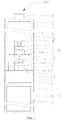
FIG. 1 is a schematic view of an electronic cigarette according to a first embodiment of the present application; -
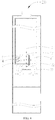
FIG. 2 is a schematic view of a cigarette cartridge of the electronic cigarette ofFIG. 1 ; -
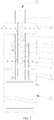
FIG. 3 is a schematic view of an atomizing assembly and a battery assembly of the electronic cigarette ofFIG. 1 ; -
FIG. 4 is a schematic view of an electronic cigarette according to a second embodiment of the present application; -
FIG. 5 is a schematic view of a cigarette cartridge of the electronic cigarette ofFIG. 4 ; -
FIG. 6 is a schematic view of an atomizing assembly and a battery assembly of the electronic cigarette ofFIG. 4 ; -
FIG. 7 is a schematic view of an electronic cigarette according to a third embodiment of the present application; and -
FIG. 8 is a schematic view of a cigarette cartridge and an atomizing head of the electronic cigarette ofFIG. 7 . - The following table lists the various components and reference numerals in the figures.
electronic cigarette cigarette cartridge 101atomizing assembly 102atomizer 10housing 11liquid storage tube 12liquid outlet device 13elastic member 14first magnetic member 15connecting seat 21atomizing end cover 22 heating structure 23second magnetic member 24battery housing 31battery 32battery switch 33mouthpiece connector 111liquid storage chamber 121air exhaust passage 122through hole 123liquid guiding hole 131first air intake hole 211second air intake hole 212smoke outlet hole 213atomizing chamber 221liquid intake hole 222battery assembly 30liquid outlet hole 132air exhaust tube 16atomizing head 25inner sleeve 124outer sleeve 125 - The present application is specifically illustrated with reference to accompanying drawings. The drawings are simplified schematic views which show fundamental structures of exemplary embodiments of the present application. Thus, merely the constructions related to the present application are shown.
- Referring to
FIG. 1 through FIG. 3 , anelectronic cigarette 100 is provided by the first embodiment of the present application. Theelectronic cigarette 100 includes anatomizer 10 and abattery assembly 30 connected to theatomizer 10. Theatomizer 10 includes acigarette cartridge 101 and anatomizing assembly 102 detachably provided at a lower end of thecigarette cartridge 101. Thebattery assembly 30 is fixedly provided at a lower end of theatomizing assembly 102. Theatomizing assembly 102 is capable of absorbing the cigarette liquid in thecigarette cartridge 101, and under the electric driving of thebattery assembly 30, the cigarette liquid is heated and atomized to form smoke to be inhaled by a user. - Referring to
FIG. 2 , specifically, thecigarette cartridge 101 includes ahousing 11, aliquid storage tube 12 fixedly received in thehousing 11, aliquid outlet device 13, anelastic member 14, and a firstmagnetic member 15. Theliquid outlet device 13, theelastic member 14 and the firstmagnetic member 15 are received in theliquid storage tube 12. Theelastic member 14 is received in theliquid outlet device 13. The firstmagnetic member 15 is slidably received in theliquid outlet device 13. - The
housing 11 substantially has a hollow cylindrical structure. Thehousing 11 has an opening at a lower end. Thehousing 11 forms amouthpiece connector 111 extending upward from the upper end of thehousing 11 and along an axial direction of thehousing 11. Themouthpiece connector 111 is in communication with the interior chamber of thehousing 11. In the illustrated embodiment, when the user inhales, themouthpiece connector 111 is held in the user's mouth directly for inhaling the smoke. It can be understood that, in alternative embodiments not shown, connecting members (not shown) can also be connected to themouthpiece connector 111, and the user holds the connecting member in mouth to perform an inhaling of the smoke. - The
liquid storage tube 12 substantially has a hollow tubular structure. The interior space of theliquid storage tube 12 forms aliquid storage chamber 121 for storing cigarette liquid. Anair exhaust passage 122 is formed between theliquid storage tube 12 and thehousing 11, wherein theair exhaust passage 122 is in communication with themouthpiece connector 111. - It can be understood that, the
liquid storage tube 12 is fixedly received in thehousing 11 by an interference fit. The external wall of theliquid storage tube 12 defines at least one groove (not shown) along an axial direction of theliquid storage tube 12. At this time, theair exhaust passage 122 is formed by the space between the groove and the internal wall of thehousing 11. Or, at least one fixing member such as a connecting rod (not shown) is provided between the external wall of theliquid storage tube 12 and the internal wall of thehousing 11, one end of the fixing member is fixedly connected to theliquid storage tube 12 and an opposite end of the fixing member is fixedly connected to thehousing 11, thereby allowing theliquid storage tube 12 to be fixedly received in thehousing 11. At this time, theair exhaust passage 122 is formed by the space between the external wall of theliquid storage tube 12 and the internal wall of thehousing 11. - Both the
housing 11 and theliquid storage tube 12 are made of transparent material or translucent material, for facilitating the user to observe the residual amount of the cigarette liquid. In the illustrated embodiment, both thehousing 11 and theliquid storage tube 12 are made of glass material. - Further, the lower end of the
liquid storage tube 12 defines a thoughhole 123 in communication with theliquid storage chamber 121. - The
liquid outlet device 13 is received in theliquid storage chamber 121. Theliquid outlet device 13 substantially has a hollow bottle-like structure. The lower end of theliquid outlet device 13 defines aliquid outlet hole 132 in communication with the interior space of theliquid outlet device 13. The lower end of theliquid outlet device 13 fixedly extends into the throughhole 123 of theliquid storage tube 12. The sidewall of theliquid outlet device 13 defines at least oneliquid guiding hole 131, theliquid guiding hole 131 is in communication with theliquid storage chamber 121 and the interior space of theliquid outlet device 13 simultaneously. In the illustrated embodiment, the number of theliquid guiding hole 131 is two, the two liquid guidingholes 131 are provided oppositely on theliquid outlet device 13. It can be understood that, in alternative embodiments not shown, the number of theliquid guiding hole 131 can be one, three or more than three. - The
elastic member 14 is retractable along the axial direction of theliquid storage tube 12. One end of theelastic member 14 elastically resists a top of theliquid outlet device 13, the other end of theelastic member 14 elastically resists the firstmagnetic member 15. The external wall of the firstmagnetic member 15 tightly contacts the internal wall of theliquid outlet device 13, so as to be able to close theliquid guiding hole 131 of theliquid outlet device 13. When thecigarette cartridge 101 is disassembled and placed separately, due to the elastic force of theelastic member 14, the firstmagnetic member 15 is moved downwardly, until the firstmagnetic member 15 closes theliquid guiding hole 131. At this time, theliquid storage chamber 121 is closed, the cigarette liquid in theliquid storage chamber 121 cannot flow into theliquid outlet device 13 via theliquid guiding hole 131. - Referring to
FIG. 3 , specifically, theatomizing assembly 102 includes a connectingseat 21 detachably connected to the lower end of thehousing 11, an atomizing end cover 22 provided at an upper end of the connectingseat 21, aheating structure 23 and a secondmagnetic member 24. Theheating structure 23 and the secondmagnetic member 24 are received in theatomizing end cover 22. - The connecting
seat 21 substantially has a cylindrical structure. The upper end of the connectingseat 21 is detachably connected to the lower end of thehousing 11. It can be understood that, by providing threads, the connectingseat 21 can be connected to thehousing 11 by a threaded connection. Or, by providing a lathing groove and a latching tab, a latching connection can be established between the connectingseat 21 and thehousing 11. Or, connecting portions between the connectingseat 21 and thehousing 11 can be provided with magnetic materials, and a magnetic connection can be established between the connectingseat 21 and thehousing 11. The detachable connection structures between the connectingseat 21 and thehousing 11 are not limited herein. - Further, the sidewall of the connecting
seat 21 defines a firstair intake hole 211. The upper end surface of the connectingseat 21 defines at least one secondair intake hole 212 in communication with the firstair intake hole 211 and theair exhaust passage 122 simultaneously. - The atomizing end cover 22 substantially has a cylindrical structure. The interior space of the atomizing end cover 22 forms an
atomizing chamber 221. Further, in order for delivering the smoke generated in the atomizing end cover 22 into the user's mouth, the upper end surface of the connectingseat 21 defines at least onesmoke outlet hole 213 corresponding to theatomizing chamber 221, and thesmoke outlet hole 213 is in communication with theatomizing chamber 221. It can be understood that, in alternative embodiments not shown, thesmoke outlet hole 213 can also be provided on the sidewall of theatomizing end cover 22, and thesmoke outlet hole 213 is in communication with theair exhaust passage 122, the target of delivering the smoke into the user's mouth can also be realized. - Further, the upper end surface of the
atomizing end cover 22 defines aliquid intake hole 222 corresponding to theliquid outlet hole 132 of theliquid outlet device 13, and theliquid intake hole 222 is in communication with theatomizing chamber 221. - The
heating structure 23 is fixedly provided in theatomizing chamber 221. Theheating structure 23 includes a heating member (not labeled) and a liquid guiding member (not labeled) which are wrapped around each other. The liquid guiding member is arranged corresponding to theliquid intake hole 222 for absorbing the cigarette liquid. The heating member is electrically connected to thebattery assembly 30. It can be understood that, the liquid guiding member can be a member having a capacity of absorbing the cigarette liquid, such as a cotton or a porous ceramic and so on. The heating member can be a member such as a heating wire or a heating plate. - The second
magnetic member 24 is fixedly provided in theatomizing chamber 221, and the secondmagnetic member 24 and the firstmagnetic member 15 are mutually repulsive. Further, when thecigarette cartridge 101 is assembled to theatomizing assembly 102, the repulsive force between the secondmagnetic member 24 and the firstmagnetic member 15 is greater than the elastic force of theelastic member 14, thereby driving the firstmagnetic member 15 to move upward. - In the illustrated embodiment, both the first
magnetic member 15 and the secondmagnetic member 24 are bar-type magnets. The north poles N of the firstmagnetic member 15 and the secondmagnetic member 24 face each other, to establish a repulsive force. It can be understood that, the shape of the magnets can be cylindrical shape or other shape and is not limited herein, so long as the firstmagnetic member 15 and the secondmagnetic member 24 repel each other. It can also be understood that, in alternative embodiments not shown, the south poles S of the firstmagnetic member 15 and the secondmagnetic member 24 face each other. It can also be understood that, the firstmagnetic member 15 and the secondmagnetic member 24 can also be electromagnets, a repulsive action between the firstmagnetic member 15 and the secondmagnetic member 24 is established by a control of the spiral orientation of the coil or the current flowing through the coil. - The
battery assembly 30 includes abattery housing 31, abattery 32 and abattery switch 33. The upper end of thebattery housing 31 is fixedly connected to the lower end of theatomizing end cover 22. Thebattery 32 is fixedly received in thebattery housing 31, and thebattery 32 is electrically connected to the heating member. Thebattery switch 33 is provided on thebattery housing 31, and thebattery switch 33 is electrically connected to thebattery 32, for controlling the power supplying of thebattery 32 for the heating member. - The assembly and the usage of the
electronic cigarette 100 of the present application is illustrated with the accompanying drawings as follows. - In the
electronic cigarette 100 provided by the present application, when it leaves factory, theatomizing assembly 102 has already been fixedly connected to thebattery assembly 30, as shown inFIG. 3 . When the user wants to inhale, thecigarette cartridge 101 is merely required to be aligned with and assembled to theatomizing assembly 102. - Referring to
FIG. 2 , when thecigarette cartridge 101 is placed separately, due to an elastic force of theelastic member 14, the firstmagnetic member 15 is moved downward under the elastic action. When the firstmagnetic member 15 moves to resist the lower end of theliquid outlet device 13, theliquid guiding hole 131 of theliquid outlet device 13 is closed by the firstmagnetic member 15, thereby closing theliquid storage chamber 121, theliquid storage chamber 121 is isolated from theliquid outlet hole 132, and the cigarette liquid cannot flow out. - Referring to
FIG. 1 , when thecigarette cartridge 101 is aligned with and assembled to theatomizing assembly 102, theatomizing assembly 102 approaches towards thecigarette cartridge 101 gradually, causing the secondmagnetic member 24 to approach the firstmagnetic member 15 gradually. When the repulsive force between the secondmagnetic member 24 and the firstmagnetic member 15 is greater than the elastic force of the firstelastic member 14, the firstmagnetic member 15 is enabled to move upward. At this time, theliquid guiding hole 131 of theliquid outlet device 13 is opened gradually, theliquid storage chamber 121 is opened to communicate with theliquid outlet device 13. The cigarette liquid flows into theliquid outlet device 13 via theliquid guiding hole 131, and then flows out from theliquid outlet hole 132 and is absorbed by the liquid guiding member by passing through theliquid intake hole 222. The cigarette liquid is heated and atomized to form smoke under the electric driving of the heating member, the smoke fills up theatomizing chamber 221. The direction indicated by the thicker arrows inFIG. 1 is the flowing direction of the cigarette liquid. - When the user inhales, external air flows into the connecting
seat 21 via the firstair intake hole 211, the smoke in theatomizing chamber 221 also flows into the connectingseat 21 via thesmoke outlet hole 213, the air mixed with the smoke then enters into the user's mouth by passing through the secondair intake hole 212, theair exhaust passage 122 and themouthpiece connector 111 successively. The direction indicated by the thinner arrows inFIG. 1 is the flowing direction of the air. - When the
cigarette cartridge 101 is disassembled and separated from theatomizing assembly 102, the secondmagnetic member 24 moves away from the firstmagnetic member 15 gradually, the repulsive force between the secondmagnetic member 24 and the firstmagnetic member 15 decreases gradually until it goes down to zero. At this time, due to an elastic force of theelastic member 14, the firstmagnetic member 15 is moved downward until the firstmagnetic member 15 closes theliquid guiding hole 131 again. Theliquid storage chamber 121 is isolated from theliquid guiding hole 131 again, and the cigarette liquid cannot flow out. At this time, thecigarette cartridge 101 is in the state shown inFIG. 2 . Therefore, even if the children open thecigarette cartridge 101 casually, a leakage of the cigarette liquid cannot occur, an accidental ingestion of the cigarette liquid by the children is avoided, thereby playing a certain role in protecting children. Further, theliquid storage chamber 121 is closed by the firstmagnetic member 15, compared to the traditional structure, the firstmagnetic member 15 does not deteriorate, and a service life is prolonged. - It can be understood that, in alternative embodiments not shown, a part of the liquid guiding member can further extend out of the atomizing end cover 22 by passing through the
liquid intake hole 222. When thecigarette cartridge 101 is connected to theatomizing assembly 102, a part of the liquid guiding member extends into theliquid outlet device 13, allowing the cigarette liquid to be absorbed by the liquid guiding member gradually, to prevent excessive cigarette liquid from flowing into theatomizing assembly 102. - In the
atomizer 10 provided by the first embodiment of the present application, according to the homogeneous repulsion principle of the magnetic poles, the movement of the firstmagnetic member 15 is controlled, thereby theliquid storage chamber 121 can be opened when thecigarette cartridge 101 is assembled, and theliquid storage chamber 121 can be closed when thecigarette cartridge 101 is disassembled. When thecigarette cartridge 101 is placed separately, a leakage of the cigarette liquid or an accidental ingestion of the cigarette liquid by the children can be avoided. - In the
electronic cigarette 100 provided by the first embodiment of the present application, because theelectronic cigarette 100 includes all the technical features ofaforementioned atomizer 10, thus theelectronic cigarette 100 has all the technical effects same as those ofaforementioned atomizer 10. - Referring to
FIG. 4 through FIG. 6 , the main difference between theelectronic cigarette 200 provided by the second embodiment and theelectronic cigarette 100 provided by the first embodiment is that, theliquid outlet device 13 is provided outside theliquid storage tube 12, and the secondmagnetic member 24 is provided outside the atomizingend cover 22. - Specifically, referring to
FIG. 5 , theliquid outlet device 13 is fixedly connected to the lower end surface of theliquid storage tube 12. Theliquid guiding hole 131 is defined in the connecting surface between theliquid outlet device 13 and theliquid storage tube 12. Theliquid outlet hole 132 is defined in theliquid outlet device 13 corresponding to theliquid guiding hole 131, and theliquid outlet hole 132 is in communication with theliquid guiding hole 131. Theelastic member 14 is retractable along the radial direction of theliquid storage tube 12. One end of theelastic member 14 elastically resists theliquid outlet device 13, and the other end of theelastic member 14 elastically resists the firstmagnetic member 15. The firstmagnetic member 15 is slidably received in theliquid outlet device 13, and is slidable along a direction perpendicular to the axial direction of theliquid storage tube 12. When thecigarette cartridge 101 is placed separately, due to an elastic action of theelastic member 14, the firstmagnetic member 15 is fixedly resisted, the firstmagnetic member 15 seals theliquid guiding hole 131 and theliquid outlet hole 132, theliquid storage chamber 121 is isolated from theliquid outlet hole 132, so that the cigarette liquid cannot flow out. - Referring to
FIG. 6 , the secondmagnetic member 24 is fixedly provided on the upper end surface of theatomizing end cover 22. Referring toFIG. 4 , in normal use, thecigarette cartridge 101 is connected to theatomizing assembly 102, the secondmagnetic member 24 is located on a side of the firstmagnetic member 15 opposite to theelastic member 14. The secondmagnetic member 24 and the firstmagnetic member 15 are mutually repulsive. The repulsive force between the secondmagnetic member 24 and the firstmagnetic member 15 is greater than the elastic force of the firstelastic member 14, thus the firstmagnetic member 15 moves and compresses theelastic member 14, and theliquid guiding hole 131 is opened finally, causing theliquid outlet hole 132 to be in communication with theliquid storage chamber 121. At this time, the cigarette liquid in theliquid storage chamber 121 flows into theliquid outlet device 13 via theliquid guiding hole 131, and then the cigarette liquid flows into theatomizing chamber 221 via theliquid outlet hole 132. The direction by the arrows inFIG. 4 indicates the flowing direction of the cigarette liquid. - In the illustrated embodiment, the north poles N of the first
magnetic member 15 and the secondmagnetic member 24 face each other. It can be understood that, in alternative embodiments not shown, the south poles S of the firstmagnetic member 15 and the secondmagnetic member 24 face each other. It can also be understood that, the firstmagnetic member 15 and the secondmagnetic member 24 can also be electromagnets, a repulsive action between the firstmagnetic member 15 and the secondmagnetic member 24 is established by a control of the spiral orientation of the coil or the current flowing through the coil. - Referring to
FIG. 5 again, when thecigarette cartridge 101 is separated from theatomizing assembly 102, the firstmagnetic member 15 is moved back to an original position due to an elastic action of theelastic member 14, finally enabling the firstmagnetic member 15 to seal theliquid guiding hole 131, and theliquid storage chamber 121 is isolated from theliquid outlet hole 132 again. When thecigarette cartridge 101 is placed separately, a leakage of the cigarette liquid and an accidental ingestion of the cigarette liquid by the children can be avoided. - The structure of the
battery assembly 30 of theelectronic cigarette 200 provided by the second embodiment is the same as that of thebattery assembly 30 in the first embodiment, which is not specifically described again. - Referring to
FIG. 7 andFIG. 8 , the main difference between theelectronic cigarette 300 provided by the third embodiment and theelectronic cigarette 100 provided by the first embodiment is that: the air intake manner and the liquid intake manner are different. In the first embodiment, the air enters from the lower end, and the liquid enters from the upper end, while in the third embodiment, the air enters from the upper end, and the liquid enters from the sidewall. - Specifically, referring to
FIG. 8 , thecigarette cartridge 101 includes ahousing 11, aliquid storage tube 12 provided in thehousing 11, aliquid outlet device 13 received in theliquid storage tube 12, anelastic member 14, a firstmagnetic member 15, and anair exhaust tube 16 connected to thehousing 11. Theelastic member 14 and the firstmagnetic member 15 are received in theliquid outlet device 13. - The
liquid storage tube 12 substantially has a columnar structure. Theliquid storage tube 12 includes aninner sleeve 124 and anouter sleeve 125 sleeved around theinner sleeve 124. A space between theinner sleeve 124 and theouter sleeve 125 forms aliquid storage chamber 121. Theliquid outlet device 13 is fixedly received in theliquid storage chamber 121, and theliquid outlet device 13 is sleeved around theinner sleeve 124. Theliquid guiding hole 131 is defined in the sidewall of theliquid outlet device 13, theliquid outlet hole 132 is defined in theinner sleeve 124 corresponding to theliquid guiding hole 131, and theliquid guiding hole 131 is in communication with theliquid outlet hole 132. Theelastic member 14 and the firstmagnetic member 15 are received in a space formed between theinner sleeve 124 and theliquid outlet device 13. One end of theelastic member 14 elastically resists theliquid outlet device 13, and the other end of theelastic member 14 elastically resists the firstmagnetic member 15. The firstmagnetic member 15 is slidably received in theliquid outlet device 13. When thecigarette cartridge 101 is placed separately, due to an elastic action of theelastic member 14, the firstmagnetic member 15 is fixedly resisted, the firstmagnetic member 15 seals theliquid guiding hole 131. At this time, theliquid storage chamber 121 is closed, and theliquid storage chamber 121 is isolated from theliquid outlet hole 132, thus the cigarette liquid in theliquid storage chamber 121 cannot flow into theliquid outlet device 13 via theliquid guiding hole 131. - Referring to
FIG. 7 andFIG. 8 , theatomizing assembly 102 of the illustrated embodiment includes a connectingseat 21, an atomizinghead 25, and a secondmagnetic member 24. - Referring to
FIG. 8 , the atomizinghead 25 is fixedly provided in theinner sleeve 124. The atomizinghead 25 defines anatomizing chamber 221 therein, and the atomizinghead 25 defines a permeable hole (not shown) corresponding to theliquid outlet hole 132 and in communication with theatomizing chamber 221. Referring toFIG. 7 , the secondmagnetic member 24 is fixedly provided in the connectingseat 21. When the connectingseat 21 is assembled to thecigarette cartridge 101, because the secondmagnetic member 24 and the firstmagnetic member 15 are mutually repulsive, and the repulsive force between the secondmagnetic member 24 and the firstmagnetic member 15 is greater than the elastic force of the firstelastic member 14, thus the firstmagnetic member 15 moves and compresses theelastic member 14, the firstmagnetic member 15 finally opens theliquid guiding hole 131, thereby causing theliquid storage chamber 121 to be in communication with theliquid outlet hole 132. At this time, the cigarette liquid in theliquid storage chamber 121 flows into theliquid outlet device 13 via theliquid guiding hole 131, and then flows into the atomizinghead 25 by passing through theliquid outlet hole 132 and the permeable hole successively, so that the cigarette liquid is heated and atomized by the heating structure (not shown) in theatomizing head 25 to form smoke. The direction indicated by the thicker arrows inFIG. 7 is the flowing direction of the cigarette liquid. - In the illustrated embodiment, the south poles S of the first
magnetic member 15 and the secondmagnetic member 24 face each other. It can be understood that, in alternative embodiments not shown, the north poles N of the firstmagnetic member 15 and the secondmagnetic member 24 face each other. It can also be understood that, the firstmagnetic member 15 and the secondmagnetic member 24 can also be electromagnets, a repulsive action between the firstmagnetic member 15 and the secondmagnetic member 24 is established by a control of the spiral orientation of the coil or the current flowing through the coil. - Referring to
FIG. 8 , thehousing 11 has a structure the same as that in the first embodiment, which is not specifically described herein. One end of theair exhaust tube 16 is connected to thehousing 11 corresponding to themouthpiece connector 111, and the other end of theair exhaust tube 16 is inserted into the atomizinghead 25. The interior space of theair exhaust tube 16 forms anair exhaust passage 122, theair exhaust passage 122 is in communication with themouthpiece connector 111 and theatomizing chamber 221 simultaneously. - Referring to
FIG. 7 , the internal wall of thehousing 11 tightly contacts the external annular surface of theliquid storage tube 12. The external wall of thehousing 11 defines a firstair intake hole 211 above theliquid storage tube 12 and in communication with theatomizing chamber 221. When the user inhales, the external air flows into theatomizing chamber 221 via the firstair intake hole 211, the air is mixed with the smoke and then flows into the user's mouth by passing through theair exhaust passage 122 and themouthpiece connector 111 successively. The direction indicated by the thinner arrows inFIG. 7 is the flow direction of the air. - It can be understood that, a part of the
inner sleeve 124 clamped between the atomizinghead 25 and theliquid outlet device 13 can be omitted. At this time, a side of the firstmagnetic member 15 contacts the internal wall of theliquid outlet device 13 to close theliquid guiding hole 131, and another side of the firstmagnetic member 15 away from theliquid outlet device 13 contacts the sidewall of the atomizinghead 25 to close the permeable hole. When thecigarette cartridge 101 is connected to theatomizing assembly 102, the firstmagnetic member 15 is moved upward to open theliquid guiding hole 131 and the permeable hole. The cigarette liquid flows into the interior of the atomizinghead 25 by passing through theliquid guiding hole 131 and the permeable hole, and is atomized to form smoke. - In the
battery assembly 30 of theelectronic cigarette 300 of the third embodiment, the firstair intake hole 211 in thebattery housing 31 is omitted, the other structures of thebattery assembly 30 are the same as those in the first embodiment, which is not specifically described herein. - The embodiments described above are merely preferred embodiments, but not intended to limit the application. Any modifications, alternatives or improvements made within the principle of the present application should be interpreted as falling within the protection scope of the present application. The claims are not limited to the features or acts described above. Rather, the proper scope of the present application is defined by the appended claims.
Claims (13)
- A cigarette cartridge comprising a liquid storage tube, a liquid outlet device, an elastic member and a first magnetic member, wherein the elastic member and the first magnetic member are received in the liquid outlet device, a liquid storage chamber is provided in the liquid storage tube, the liquid outlet device is provided with a liquid guiding hole in communication with the liquid storage chamber, the cigarette cartridge is further provided with a liquid outlet hole in communication with the liquid guiding hole, the first magnetic member is slidably received in the liquid outlet device, one end of the elastic member elastically resists an inner wall of the liquid outlet device, the other end of the elastic member elastically resists the first magnetic member, the first magnetic member is capable of closing the liquid guiding hole under an action of the elastic member.
- The cigarette cartridge according to claim 1, wherein the liquid outlet device is received in the liquid storage tube, the first magnetic member is slidable along an axial direction of the liquid storage tube.
- The cigarette cartridge according to claim 2, wherein the liquid guiding hole is defined in a sidewall of the liquid outlet device, the liquid outlet hole is defined at a lower end of the liquid outlet device.
- The cigarette cartridge according to claim 2 or 3, wherein a lower end of the liquid storage tube defines a though hole in communication with the liquid storage chamber, a lower end of the liquid outlet device fixedly extends into the through hole of the liquid storage tube.
- The cigarette cartridge according to claim 1, wherein the liquid outlet device is provided outside the liquid storage tube and connected to a lower end of the liquid storage tube, the first magnetic member is slidable along a radial direction of the liquid storage tube.
- The cigarette cartridge according to claim 5, wherein the liquid guiding hole is defined in a connecting surface between the liquid outlet device and the liquid storage tube, the liquid outlet hole is defined in the liquid outlet device corresponding to the liquid guiding hole.
- The cigarette cartridge according to claim 1, wherein the liquid storage tube comprises an inner sleeve and an outer sleeve sleeved around the inner sleeve, the liquid storage chamber is formed by a space between the outer sleeve and the inner sleeve, the liquid outlet device is received in the liquid storage chamber and sleeved around the inner sleeve, both the elastic member and the first magnetic member are provided in a space between the inner sleeve and the liquid outlet device.
- The cigarette cartridge according to claim 7, wherein the liquid outlet hole is defined in the inner sleeve, the liquid guiding hole is defined in a sidewall of the liquid outlet device corresponding to the liquid outlet hole.
- An atomizer comprising the cigarette cartridge according to any one of claims 1 to 8, wherein the atomizer further comprises an atomizing assembly connected to the cigarette cartridge, the atomizing assembly comprises a second magnetic member, the second magnetic member and the first magnetic member are mutually repulsive, when the atomizing assembly is assembled to the cigarette cartridge, a repulsive force between the second magnetic member and the first magnetic member is greater than an elastic force of the elastic member, so that the first magnetic member moves and compresses the elastic member to open the liquid guiding hole, causing the liquid storage chamber to be in communication with the liquid outlet hole.
- The atomizer according to claim 9, wherein the atomizing assembly comprises an atomizing end cover connected to the cigarette cartridge, an interior space of the atomizing end cover forms an atomizing chamber, the atomizing end cover defines, corresponding to the liquid outlet hole, a liquid intake hole in communication with the atomizing chamber, the second magnetic member is fixedly received in the atomizing chamber.
- The atomizer according to claim 9, wherein the atomizing assembly comprises an atomizing end cover connected to the cigarette cartridge, an interior space of the atomizing end cover forms an atomizing chamber, the atomizing end cover defines, corresponding to the liquid outlet hole, a liquid intake hole in communication with the atomizing chamber, the second magnetic member is provided outside the atomizing end cover and fixedly provided on the upper end of the atomizing end cover.
- The atomizer according to claim 9, wherein the atomizing assembly comprises a connecting seat and an atomizing head, the connecting seat is connected to the cigarette cartridge, the atomizing head is fixedly provided in the inner sleeve, an atomizing chamber is defined in the atomizing head, the atomizing head defines, corresponding to the liquid outlet hole, a permeable hole in communication with the atomizing chamber, the second magnetic member is fixedly received in the connecting seat.
- An electronic cigarette comprising the atomizer according to any one of claims 9 to 12.
Applications Claiming Priority (2)
| Application Number | Priority Date | Filing Date | Title |
|---|---|---|---|
| CN201710037941.6A CN106723380A (en) | 2017-01-19 | 2017-01-19 | Cigarette bullet, atomizer and its electronic cigarette |
| PCT/CN2017/095286 WO2018133369A1 (en) | 2017-01-19 | 2017-07-31 | Cigarette cartridge, atomizer and electronic cigarette thereof |
Publications (2)
| Publication Number | Publication Date |
|---|---|
| EP3569074A1 true EP3569074A1 (en) | 2019-11-20 |
| EP3569074A4 EP3569074A4 (en) | 2020-01-15 |
Family
ID=58944034
Family Applications (1)
| Application Number | Title | Priority Date | Filing Date |
|---|---|---|---|
| EP17892909.7A Withdrawn EP3569074A4 (en) | 2017-01-19 | 2017-07-31 | Cigarette cartridge, atomizer and electronic cigarette thereof |
Country Status (4)
| Country | Link |
|---|---|
| US (1) | US20190335814A1 (en) |
| EP (1) | EP3569074A4 (en) |
| CN (1) | CN106723380A (en) |
| WO (1) | WO2018133369A1 (en) |
Families Citing this family (12)
| Publication number | Priority date | Publication date | Assignee | Title |
|---|---|---|---|---|
| EP3100621B1 (en) | 2015-06-02 | 2021-08-04 | Fontem Holdings 1 B.V. | Electronic smoking device |
| CN106723380A (en) * | 2017-01-19 | 2017-05-31 | 常州市派腾电子技术服务有限公司 | Cigarette bullet, atomizer and its electronic cigarette |
| CN106579569B (en) * | 2017-01-19 | 2019-07-12 | 常州市派腾电子技术服务有限公司 | Smoke grenade, atomizer and its electronic cigarette |
| KR102372858B1 (en) * | 2018-07-19 | 2022-03-08 | 주식회사 케이티앤지 | Electronic vaporizer |
| CN109105958B (en) * | 2018-08-17 | 2024-07-12 | 深圳市合元科技有限公司 | Heating components, atomizing cores, atomizers and electronic cigarettes |
| CN111248511A (en) * | 2020-03-16 | 2020-06-09 | 深圳市吉迩科技有限公司 | Electronic cigarette and cigarette cartridge thereof |
| JP7713960B2 (en) * | 2020-05-15 | 2025-07-28 | フィリップ・モーリス・プロダクツ・ソシエテ・アノニム | Aerosol-generating article with a liquid reservoir and a movable sealing member - Patents.com |
| KR102686960B1 (en) * | 2021-06-08 | 2024-07-22 | 주식회사 케이티앤지 | Aerosol generating device |
| CN113303513A (en) * | 2021-06-20 | 2021-08-27 | 张鹏程 | Atomizing device of electronic cigarette |
| CN113995169B (en) * | 2021-11-10 | 2024-09-27 | 吉万(深圳)科技有限公司 | Combined aerosol generating device |
| KR20240100449A (en) * | 2021-12-22 | 2024-07-01 | 니코벤처스 트레이딩 리미티드 | aerosol delivery system |
| CN116725250B (en) * | 2023-06-30 | 2025-12-19 | 深圳市优维尔科技有限公司 | Novel electronic cigarette integrated with electronic lock |
Family Cites Families (13)
| Publication number | Priority date | Publication date | Assignee | Title |
|---|---|---|---|---|
| US6776905B2 (en) * | 2002-08-02 | 2004-08-17 | Jen-Pen Chang | Magnetizing and activating processing unit for liquid material |
| CN203828081U (en) * | 2014-05-22 | 2014-09-17 | 惠州市凯尔文科技有限公司 | Oil cylinder separating type shisha atomizer |
| CN204259818U (en) * | 2014-05-30 | 2015-04-15 | 深圳市麦克韦尔科技有限公司 | Electronic cigarette and its pod tube |
| WO2016033721A1 (en) * | 2014-09-01 | 2016-03-10 | 惠州市吉瑞科技有限公司 | Electronic cigarette |
| CN204317500U (en) * | 2014-12-01 | 2015-05-13 | 深圳佳品健怡科技有限公司 | A kind of electronic cigarette |
| CN104544570B (en) * | 2014-12-31 | 2017-12-08 | 深圳麦克韦尔股份有限公司 | Inhalator and its atomizing component |
| CN204444248U (en) * | 2015-01-23 | 2015-07-08 | 深圳市合元科技有限公司 | Atomizer and electronic cigarette |
| WO2016141555A1 (en) * | 2015-03-10 | 2016-09-15 | 深圳麦克韦尔股份有限公司 | Electronic cigarette |
| CN204444261U (en) * | 2015-03-10 | 2015-07-08 | 深圳市麦克韦尔科技有限公司 | Electronic cigarette |
| CN204444260U (en) * | 2015-03-10 | 2015-07-08 | 深圳市麦克韦尔科技有限公司 | Electronic cigarette and cell apparatus thereof |
| CN106333388B (en) * | 2016-11-11 | 2023-09-22 | 周成龙 | Electronic cigarette atomizing assembly |
| CN106579569B (en) * | 2017-01-19 | 2019-07-12 | 常州市派腾电子技术服务有限公司 | Smoke grenade, atomizer and its electronic cigarette |
| CN106723380A (en) * | 2017-01-19 | 2017-05-31 | 常州市派腾电子技术服务有限公司 | Cigarette bullet, atomizer and its electronic cigarette |
-
2017
- 2017-01-19 CN CN201710037941.6A patent/CN106723380A/en active Pending
- 2017-07-31 EP EP17892909.7A patent/EP3569074A4/en not_active Withdrawn
- 2017-07-31 WO PCT/CN2017/095286 patent/WO2018133369A1/en not_active Ceased
-
2019
- 2019-07-15 US US16/512,217 patent/US20190335814A1/en not_active Abandoned
Also Published As
| Publication number | Publication date |
|---|---|
| CN106723380A (en) | 2017-05-31 |
| US20190335814A1 (en) | 2019-11-07 |
| EP3569074A4 (en) | 2020-01-15 |
| WO2018133369A1 (en) | 2018-07-26 |
Similar Documents
| Publication | Publication Date | Title |
|---|---|---|
| EP3569074A1 (en) | Cigarette cartridge, atomizer and electronic cigarette thereof | |
| CN209965226U (en) | e-cigarette | |
| CN207011680U (en) | Atomizer and its electronic cigarette | |
| US11871794B2 (en) | Atomizer of electronic cigarette providing child protection function | |
| CN206687166U (en) | The electronic smoke atomizer structure and electronic smoke atomizer of controllable tobacco juice | |
| CN106579569B (en) | Smoke grenade, atomizer and its electronic cigarette | |
| WO2016172847A1 (en) | Inhaler and atomization component thereof | |
| CN206413756U (en) | Liquid storage component, atomizer and its electronic cigarette | |
| WO2019196688A1 (en) | Atomizer and electronic cigarette | |
| EP3549459A1 (en) | Cartridge and atomizer thereof, and electronic cigarette | |
| CN211746942U (en) | Cover assembly, atomizer and aerosol generating device | |
| CN106455696A (en) | Electronic cigarette and method for adjusting air intake of electronic cigarette | |
| CN210695958U (en) | Condensate recovery structure of electronic cigarette atomizer | |
| US20220071283A1 (en) | Atomizer and electronic cigarette | |
| CN210137809U (en) | Atomizer and electronic cigarette | |
| CN211091883U (en) | Electronic cigarette with condensate recovery structure | |
| CN111317180A (en) | Atomizer and electronic cigarette | |
| CN204796738U (en) | Inhaler and atomization component thereof | |
| CN206687176U (en) | Atomizer and its electronic cigarette | |
| CN205865992U (en) | Modified electronics atomizing cigarette | |
| CN209346100U (en) | Atomizer and electronic cigarette | |
| CN209376683U (en) | The atomizer and electronic cigarette of removable atomization core | |
| US12193509B2 (en) | Cartridge and electronic cigarette | |
| WO2022042173A1 (en) | Atomizer and aerosol generating device | |
| CN211211454U (en) | e-cigarette |
Legal Events
| Date | Code | Title | Description |
|---|---|---|---|
| PUAI | Public reference made under article 153(3) epc to a published international application that has entered the european phase |
Free format text: ORIGINAL CODE: 0009012 |
|
| 17P | Request for examination filed |
Effective date: 20190812 |
|
| AK | Designated contracting states |
Kind code of ref document: A1 Designated state(s): AL AT BE BG CH CY CZ DE DK EE ES FI FR GB GR HR HU IE IS IT LI LT LU LV MC MK MT NL NO PL PT RO RS SE SI SK SM TR |
|
| AX | Request for extension of the european patent |
Extension state: BA ME |
|
| A4 | Supplementary search report drawn up and despatched |
Effective date: 20191218 |
|
| RIC1 | Information provided on ipc code assigned before grant |
Ipc: A24F 47/00 20060101AFI20191212BHEP Ipc: A61M 15/06 20060101ALI20191212BHEP Ipc: A61M 11/04 20060101ALI20191212BHEP |
|
| DAV | Request for validation of the european patent (deleted) | ||
| DAX | Request for extension of the european patent (deleted) | ||
| 17Q | First examination report despatched |
Effective date: 20200409 |
|
| STAA | Information on the status of an ep patent application or granted ep patent |
Free format text: STATUS: THE APPLICATION HAS BEEN WITHDRAWN |
|
| 18W | Application withdrawn |
Effective date: 20200810 |