EP3569039B1 - Deaktivieren von plasmalichtbogenbrennern sowie zugehörige systeme und verfahren - Google Patents
Deaktivieren von plasmalichtbogenbrennern sowie zugehörige systeme und verfahren Download PDFInfo
- Publication number
- EP3569039B1 EP3569039B1 EP18702039.1A EP18702039A EP3569039B1 EP 3569039 B1 EP3569039 B1 EP 3569039B1 EP 18702039 A EP18702039 A EP 18702039A EP 3569039 B1 EP3569039 B1 EP 3569039B1
- Authority
- EP
- European Patent Office
- Prior art keywords
- torch
- plasma
- control circuit
- switch
- circuit
- Prior art date
- Legal status (The legal status is an assumption and is not a legal conclusion. Google has not performed a legal analysis and makes no representation as to the accuracy of the status listed.)
- Active
Links
Images

Classifications
-
- H—ELECTRICITY
- H05—ELECTRIC TECHNIQUES NOT OTHERWISE PROVIDED FOR
- H05H—PLASMA TECHNIQUE; PRODUCTION OF ACCELERATED ELECTRICALLY-CHARGED PARTICLES OR OF NEUTRONS; PRODUCTION OR ACCELERATION OF NEUTRAL MOLECULAR OR ATOMIC BEAMS
- H05H1/00—Generating plasma; Handling plasma
- H05H1/24—Generating plasma
- H05H1/26—Plasma torches
- H05H1/32—Plasma torches using an arc
- H05H1/34—Details, e.g. electrodes, nozzles
- H05H1/36—Circuit arrangements
-
- B—PERFORMING OPERATIONS; TRANSPORTING
- B23—MACHINE TOOLS; METAL-WORKING NOT OTHERWISE PROVIDED FOR
- B23K—SOLDERING OR UNSOLDERING; WELDING; CLADDING OR PLATING BY SOLDERING OR WELDING; CUTTING BY APPLYING HEAT LOCALLY, e.g. FLAME CUTTING; WORKING BY LASER BEAM
- B23K10/00—Welding or cutting by means of a plasma
- B23K10/006—Control circuits therefor
-
- B—PERFORMING OPERATIONS; TRANSPORTING
- B23—MACHINE TOOLS; METAL-WORKING NOT OTHERWISE PROVIDED FOR
- B23K—SOLDERING OR UNSOLDERING; WELDING; CLADDING OR PLATING BY SOLDERING OR WELDING; CUTTING BY APPLYING HEAT LOCALLY, e.g. FLAME CUTTING; WORKING BY LASER BEAM
- B23K9/00—Arc welding or cutting
- B23K9/10—Other electric circuits therefor; Protective circuits; Remote controls
-
- H—ELECTRICITY
- H05—ELECTRIC TECHNIQUES NOT OTHERWISE PROVIDED FOR
- H05H—PLASMA TECHNIQUE; PRODUCTION OF ACCELERATED ELECTRICALLY-CHARGED PARTICLES OR OF NEUTRONS; PRODUCTION OR ACCELERATION OF NEUTRAL MOLECULAR OR ATOMIC BEAMS
- H05H1/00—Generating plasma; Handling plasma
- H05H1/24—Generating plasma
- H05H1/26—Plasma torches
- H05H1/32—Plasma torches using an arc
- H05H1/34—Details, e.g. electrodes, nozzles
- H05H1/3473—Safety means
Definitions
- This application relates generally to plasma arc torches, and more specifically to disabling plasma arc torches to plasma arc systems and to related systems and methods.
- a plasma arc torch generally includes a torch body, an electrode mounted within the body, a nozzle with a central exit orifice, electrical connections, passages for cooling and arc control fluids, a swirl ring to control the fluid flow patterns, a power supply and a means to control the operation of the torch.
- a plasma arc torch generates a constricted ionized jet of plasma gas with high temperature and high momentum.
- the plasma jet typically exits the nozzle orifice of the torch typically at a temperature of between 15,000-50,000 degrees centigrade at a typical velocity of up to 7,000 m/s.
- a plasma jet with these temperatures and velocities produces extreme rates of heat transfer which are necessary to cut rapidly through metals. Such extreme rates of heat transfer can result in a serious hazard of traumatic burns to the operator and other workers in close proximity to the jet exiting the plasma arc torch.
- the operating instructions for commercial plasma arc torches usually instruct the operator to disable the power supply before disassembling the torch for service or when leaving the plasma arc torch unattended and warn the operator of possible injuries (e.g., electric shock) resulting from a failure to follow correct operating procedures. It is, however, frequently observed in practice that operators fail to follow the manufacturer's instructions and warnings.
- Some plasma arc torches can be trigger-activated devices. That is, the torch generates a plasma stream in response to operator activation of a trigger.
- Accidents can occur when the operator handles the torch in certain scenarios without turning off the power supply (e.g., changing consumables) or inadvertently activates the trigger controlling the plasma stream (e.g., to inadvertently fire the torch).
- Accidents can also occur with plasma arc torches when the operator places the torch body on a hard surface while attending to other tasks.
- the trigger can be inadvertently activated if objects like clothing or building materials are placed on top the torch. For example, in some cases, this can occur when a torch is placed in a user's pocket, such as while climbing or negotiating uneven terrain. Additionally, accidents can occur if a torch is dropped such that its trigger strikes a solid object.
- US5039837A discloses an example of a plasma torch having a torch handle comprising safety systems and related safety methods.
- the invention discloses a plasma arc torch according to claim 1.
- the invention discloses a safety circuit for a plasma arc torch according to claim 11.
- the invention discloses a method of disengaging a plasma control circuit within a plasma arc torch according to claim 13. Advantageous embodiments are disclosed in the dependent claims.
- the user of a plasma cutting system can face a risk of potentially firing the torch accidentally (which can lead to injury) or be required to reset the power supply to cycle the system after replacing consumables (which can lead to an inconvenience of frequent forced trips to a distant power supply).
- the systems and methods described herein can advantageously reduce these issues by providing mechanisms to allow the user to temporarily stop (e.g., prevent) the torch from firing, upon an action by the user at the torch, and consequently re-enable the torch for operation, upon a subsequent action by the user at the torch. That is, by limiting current flow to the consumables (e.g., including pilot current), the torch can be less likely to inadvertently fire when handling.
- a user will be able to change consumables safely without the requirement of accessing the power supply, without compromising safety.
- the systems and methods described herein can include one or more circuits, physical switch assemblies, or software/firmware programs that are configured to temporarily prevent current from flowing to the torch tip so that they can be handled and removed/replaced while, in some aspects, also bypassing a cap sense switch (e.g., a sensor circuit configured to determine and confirm that a consumable is installed in the torch), which permits the user to remove and replace the consumables without tripping the system and requiring a reset. That is, in some conventional systems, if the consumables are simply removed, the cap sensor switch will trip and the system will not be able to fire until reset.
- a cap sense switch e.g., a sensor circuit configured to determine and confirm that a consumable is installed in the torch
- hand torch operations typically have been programmed to carry out the following sequence, and ask the user/operator to: 1) turn off the power supply at the physical power supply (e.g., by flipping a switch or switches on the power supply) to stop electricity from flowing to the torch; 2) change the consumables; and 3) turn on the power supply (e.g., by flipping a switch or switches on the power supply).
- the shut-off power supply step either due to a lack-of-willingness or inconvenience (e.g., the power supply can be located far away or be difficult to access from the operation site).
- the torch can routinely be located several meters away from the power supply.
- the power supply will typically shut-off automatically once the consumable is loosened from the torch and a cap sensor switch is triggered.
- the cap sensor switch is triggered, the user typically won't be able to operate (e.g., fire) the torch unless he or she walks over to the power supply and manually recycles (turns-it-off and then turns-it-on) the power supply.
- Such required cycling away from the torch can be an issue in distant or hard-to-reach or access places, causing delays in work.
- torches are typically designed and manufactured to be so small and compact for better or more convenient handling and operation that available space on the torch itself can be limited. That is, available space on a torch may be limited only to that occupied by existing switches and delivery systems, such that additional components, such as the torch disable switches described herein, cannot be arranged on the torch. Additionally, particularly in view of this premium for space, in some conventional systems, torches may not include additional components or switches at all, particularly those that can add to the complexity of the torch design and introduces one or more failure modes. Additionally, such additional components and switches would have typically been expected to reduce torch robustness and durability in the field. Whereas, the systems and methods described herein have been developed to take advantage of the minimal design space, providing a compact and effective safety solution with a torch disable switch.
- the systems and methods described herein can be implemented to allow a user to more safely handle a plasma arc torch, for example, during consumable replacement, by using one or more switches to limit plasma current, including pilot current, from reaching the consumables. Additionally, in some aspects, the systems and methods described herein can include bypassing a cap sensor switch circuit so that consumables can be safely handled and replaced, and then the system can be used without requiring the user to cycle the power supply.
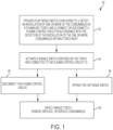
- methods (50) of disengaging a plasma control circuit within the plasma arc torch of a plasma processing system to place the torch into a mode for handling or replacing consumables, such as a safety-locked mode can include providing: a plasma control circuit within a plasma arc torch, configured to convey a current from the plasma cutting system through the plasma arc torch to one or more consumables disposed in the torch body, and a cap sense switch connected to the plasma control circuit and configured to: i) detect an installation of one or more of the consumables in the plasma arc torch, and ii) connect or disconnect the plasma control circuit in accordance with the detection of the installation of the one or more consumables.
- a plasma control circuit within a plasma arc torch configured to convey a current from the plasma cutting system through the plasma arc torch to one or more consumables disposed in the torch body
- a cap sense switch connected to the plasma control circuit and configured to: i) detect an installation of one or more of the consumables in the plasma arc torch, and ii) connect
- the methods can, as detailed below, include sliding (e.g., activating) a switch disposed on the torch body and connected to the plasma control circuit.
- the switch can be configured to disconnect the plasma control circuit to limit current flow, including pilot current.
- the switch can control system electronics so that if the trigger (e.g., start button) is depressed, such as inadvertently pressed during handling, the system nonetheless does not initiate a plasma arc.
- the switch can be configured to disconnect an electrical circuit directly providing current to the consumables or can create a physical blockage or mechanical disconnection of a second switch (e.g., the trigger).
- the switch can be used to disconnect or otherwise prevent current from flowing to the consumables so that the consumables can be safely handled for maintenance or replacement.
- the switch can also be configured to bypass a cap sense switch.
- a cap sense switch is typically configured so that, once tripped (e.g., detecting that a consumable is not installed), the system will require a recycle (to restart the system) before permitting a user to fire the torch (e.g., to initiate a plasma arc) after consumables have been replaced.
- the cap sense switch can be bypassed during consumable replacement, for example, by forming or closing a circuit (e.g., a cap sense bypass circuit) in parallel to the cap sense switch.
- a processing system can be configured to detect a shutdown caused by cap sense switch due to a consumable being removed from the torch and can indicate to the user a proper, or more desirable shutdown sequence, including first disabling the torch using the torch disable switch described below.
- the plasma control circuit can be disconnected and the cap sense switch can be bypassed to close the circuit in parallel to the cap sense switch in a single user input.
- a single switch can be used to disconnect the plasma control circuit and close the circuit to bypass the cap sense switch.
- the single input can include sliding the switch.
- each of these connections or disconnections can be achieved using different switches.
- the disconnection of the plasma control circuit and the connection of the bypass circuit can occur in any of a variety of different timing sequences.
- activating the switch disconnects the plasma control circuit before bypassing the cap sense switch. In some cases, the two can happen substantially simultaneously.
- the methods can include sliding (e.g., de-activating) the switch to re-connect the plasma control circuit to place the torch into a use mode.
- sliding the switch can also open or disconnect the circuit in parallel to the cap sense switch to place the torch into a use mode. For example, disconnecting the cap sense bypass circuit can re-establish the safety and security of a proper cap sense circuit. Additionally, reconnecting the plasma control circuit can re-enable the torch for use.
- the second switch e.g., trigger
- the second switch can be activated to initiate a firing sequence to generate a plasma arc.
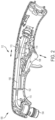
- mechanical and electrical systems implemented to carry out the methods described herein can include a plasma arc torch (e.g., a handheld plasma arc torch) 100 having a torch grip (e.g., torch handle)) 102, a torch body (to house or position a set of consumables) 104 at a distal end of the torch handle 102 configured to generate a plasma arc, a gas delivery line 106 to provide processing gas to the torch body 104, an operator interface switch (e.g., trigger) 108 to be used to initiate a firing sequence, and a torch disable switch 112 disposed on the torch handle 102.
- a plasma arc torch e.g., a handheld plasma arc torch
- a torch grip e.g., torch handle
- a torch body to house or position a set of consumables
- a gas delivery line 106 to provide processing gas to the torch body 104
- an operator interface switch e.g., trigger
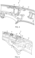
- the plasma arc torch 100 can be an air-cooled torch (e.g., a handheld torch). In some cases, as discussed below with respect to Figure 6 , the plasma arc torch can be a liquid-cooled, mechanized torch. In some embodiments, the operator interface switch can be remote from the torch, such as within a controller for a mechanized torch. That is, mechanized torches may not include a trigger switch on them.
- the torch 100 includes a cap sense switch (e.g., cap sense sensor) 110 disposed within the torch handle connected to the plasma control circuit and configured to detect a presence of one or more of the consumables in the torch body 104.
- the cap sense switch 110 is typically configured to open or close the plasma control circuit in accordance with the detection of the presence of the one or more consumables. That is, when the cap sense switch 110 does not detect that a substantially complete set of consumables are installed in the torch 100, it can prevent the plasma control circuit from initiating a plasma arc.
- the torch disable switch 112 includes a user interface (e.g., a physical interface) 113 connected (e.g., mechanically or electrically connected) to the plasma control circuit disconnect to operatively connect or disconnect the plasma control circuit with the plasma control circuit disconnect in response to an operator input (e.g., sliding a switch).
- a user interface e.g., a physical interface
- the torch disable switch 112 can include a physical switch 113 that can be manually activated by the user.
- the torch disable switch 112 can include a mechanically activated single purpose electrical switch (e.g., a toggle switch or slide switch).
- the torch disable switch 112 can be in communication (e.g., wired or wireless communication) with a system controller and the plasma control circuit so that when the switch is moved, the plasma control circuit is electrically disconnected.
- operating the torch disable switch 112 can open or close an electronic circuit providing current to the torch body 104 and consumables.
- the circuit board 116 can interface with one or more other electronic components or systems to operate or control other torch systems.
- the circuit board 116 can be used for, or implemented with other torch control systems that can make it easier for the user to, control and monitor the plasma torch power supply at the torch itself (i.e., rather than back at the power supply/controller).
- the circuit board and integrated systems can permit the user to not only control the torch disable switch at the torch but also to adjust and monitor/observe (e.g., visually see) settings of the plasma process such as amperage, gas flow, mode, etc.
- a control display 120 on top of the circuit board (and exposed for use) can include visual indicators (e.g., LEDs).
- control display 120 includes at least one button, which can be separate from the torch disable switch, which can be used to adjust current level and/or torch mode.
- all of these added functions can be incorporated into one board for better use of space, ease of manufacturing, cost, etc., while the control interface can still be compact and all in one place.
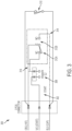
- the safety circuit 300 includes a cap sense switch circuit 310 configured to detect a presence of one or more of the consumables in the plasma arc torch.
- the cap sense switch circuit 310 is configured to connect or disconnect the plasma start circuit 302 in accordance with the detection of the presence of the one or more consumables, as discussed above.
- the safety circuit 300 can also include a cap sense bypass circuit 314 configured to provide a current in parallel to the cap sense switch 310. As discussed above, the cap sense bypass circuit 314 can be closed so that even if the cap sense switch is opened (e.g., when consumables are removed), the circuit can remain closed to prevent a system reset from being required.
- the safety circuit also includes a means 312A to open the plasma start circuit 302 to limit current to the one or more consumables and, in some aspects, a means 312B to close the cap sense bypass circuit 314.
- the means 312A is a means, separate from the switching means, to open the plasma start circuit to limit current flow, including pilot current, to the one or more consumables.
- switches can be used to open and close the plasma start circuit 302 and the cap bypass circuit 314.
- the means 312A to open the plasma start circuit and the means 312B to close the cap sense bypass circuit comprise a common component.
- the common component can include one torch disable switch 112 or user interface.
- the means to open the plasma start circuit can be separate from the switching means connected to the plasma control circuit and configured to generate a plasma arc from the tip of the torch.
- the plasma control circuit disconnect can be configured to selectively disconnect the plasma control circuit, and selectively connect the bypass circuit to bypass the cap sense switch based on a single operator input, such as a single input to the torch disable switch 112.
- the plasma control circuit disconnect can be configured to selectively disconnect the plasma control circuit, and selectively connect the bypass circuit to bypass the cap sense switch substantially simultaneously.
- the locations and respective orientations of the trigger 108 and the torch disable switch 112 can be configured to further reduce or limit unintentional firing of the torch and related possible injuries resulting therefrom.
- the trigger 108 and the torch disable switch 112 can be configured to move in different (e.g., substantially perpendicular) directions so that when the torch is handled, it is less likely that both switches will accidently be depressed at the same time, such as when a torch is slid into a user's pocket or dropped onto another surface.
- a mechanized torch e.g., a torch to be mounted to and moved with a gantry (e.g., robotic or CNC system)
- a gantry e.g., robotic or CNC system
- a torch disable switch 112 mounted in, on, or along a torch handle 102, to prevent current from flowing to the torch body 104 and consumables to that they can be safely handled (e.g., replaced).
- the torch disable switch 112 can include a user interface (e.g., a physical interface) 113 connected (e.g., mechanically or electrically connected) to the plasma control circuit disconnect to operatively connect or disconnect the plasma control circuit with the plasma control circuit disconnect in response to an operator input (e.g., sliding a switch).
- the torch disable switch 112 can include a physical switch 113 that can be manually activated by the user. While a mechanized torch is not typically manually handled by a user during use, in this context, the term torch grip (e.g., handle) 102 is used to refer to a body or frame of the torch that houses other components and mounts to the gantry for use.
- a torch operator interface 108 used to turn the torch on and off for use can be located remote from the torch 200 itself, for example on a controller on a CNC machine. That is, in some embodiments, the torch disable switch 112 can be operated by the user on the torch itself. Additionally or alternatively, the torch disable switch 112 can be operated at the torch controller.
- the various features or aspects of the example embodiments described herein can be combined or implemented in combination with one another.
- features of the torch disable switch described with respect to the handheld torch examples can be implemented or combined with the mechanized examples.
- aspects of one type of torch disable switch e.g., an electronic switch mounted on a circuit board embodiment
- another type of switch e.g., a toggle or slide switch embodiment
Landscapes
- Engineering & Computer Science (AREA)
- Physics & Mathematics (AREA)
- Plasma & Fusion (AREA)
- Spectroscopy & Molecular Physics (AREA)
- Mechanical Engineering (AREA)
- Plasma Technology (AREA)
- Arc Welding In General (AREA)
Claims (15)
- Plasmalichtbogenbrenner (100) für ein Plasmaschneidsystem, wobei der Plasmalichtbogenbrenner (100) Folgendes umfasst:einen Brennergriff (102);einen Bedienerschnittstellenschalter (108), der mit einer Plasmasteuerschaltung verbunden ist: i) ausgelegt zum Steuern eines Stroms von dem Plasmaschneidsystem durch den Plasmalichtbogenbrenner (100) zu einem oder mehreren Verbrauchsmaterialien, die an einem distalen Ende des Brennergriffs (102) angeordnet sind, und ii) ausgelegt zum Initiieren der Erzeugung eines Plasmalichtbogens von einer Spitze des Brenners; undeinen Brennersperrschalter (112), der von dem Bedienerschnittstellenschalter (108) getrennt ist, an dem Brennergriff (102) angeordnet ist und mit der Plasmasteuerschaltung verbunden ist, wobei der Brennersperrschalter (112) Folgendes beinhaltet:einen Plasmasteuerschaltungstrennschalter, ausgelegt zum selektiven Verbinden und Trennen der Plasmasteuerschaltung, um einen Stromfluss, einschließlich Pilotstrom, zu dem einen oder den mehreren Verbrauchsmaterialien zu verhindern, undeine Benutzerschnittstelle (113), die mit dem Plasmasteuerschaltungstrennschalter verbunden ist, wobei die Benutzerschnittstelle (113) dazu ausgelegt ist, die Plasmasteuerschaltung als Reaktion auf eine Bedienereingabe operativ mit dem Plasmasteuerschaltungstrennschalter zu verbinden oder zu trennen,dadurch gekennzeichnet, dass der Plasmalichtbogenbrenner (100) ferner einen Kappenerfassungsschalter (110) umfasst, der innerhalb des Brennergriffs (102) angeordnet ist, mit der Plasmasteuerschaltung verbunden ist und dazu ausgelegt ist, ein Vorhandensein eines oder mehrerer Verbrauchsmaterialien zu detektieren, wobei der Kappenerfassungsschalter (110) ferner dazu ausgelegt ist, die Plasmasteuerschaltung gemäß der Detektion des Vorhandenseins des einen oder der mehreren Verbrauchsmaterialien zu öffnen oder zu schließen.
- Plasmalichtbogenbrenner (100) nach Anspruch 1, wobei der Plasmasteuerschaltungstrennschalter ferner dazu ausgelegt ist, eine Umgehungsschaltung selektiv zu verbinden oder zu trennen, um den Kappenerfassungsschalter (110) zu umgehen,wobei der Plasmasteuerschaltungstrennschalter optional zu Folgendem ausgelegt ist: i) selektives Trennen der Plasmasteuerschaltung und ii) selektives Verbinden einer Umgehungsschaltung zum Umgehen des Kappenerfassungsschalters (110) basierend auf einer einzigen Bedienereingabe,wobei der Plasmasteuerschaltungstrennschalter optionaler zu Folgendem ausgelegt ist: i) selektives Trennen der Plasmasteuerschaltung und ii) selektives Verbinden der Umgehungsschaltung zum Umgehen des Kappenerfassungsschalters im Wesentlichen gleichzeitig.
- Plasmalichtbogenbrenner (100) nach Anspruch 1, wobei der Brennersperrschalter (112) einen Federklemmenmechanismus (115) beinhaltet.
- Plasmalichtbogenbrenner (100) nach Anspruch 1, wobei es sich bei dem Plasmalichtbogenbrenner (100) um ein luftgekühltes Plasmaschneidsystem handelt.
- Plasmalichtbogenbrenner (100) nach Anspruch 1, wobei es sich bei der Benutzerschnittstelle (113) um einen Schiebemechanismus mit einer ersten Stellung und einer zweiten Stellung handelt,
wobei die erste Stellung und die zweite Stellung optional farbcodierte Indikatoren sind. - Plasmalichtbogenbrenner (100) nach Anspruch 1, wobei der Brennersperrschalter (112) die Plasmasteuerschaltung mechanisch trennt.
- Plasmalichtbogenbrenner (100) nach Anspruch 1, wobei die Benutzerschnittstelle (113) dazu ausgelegt ist, in einer axialen Richtung im Wesentlichen parallel zu einer Längsachse des Brennergriffs (102) bewegt zu werden.
- Plasmalichtbogenbrenner (100) nach Anspruch 1, wobei der Bedienerschnittstellenschalter (108) entfernt von dem Brenner angeordnet ist.
- Plasmalichtbogenbrenner (100) nach Anspruch 1, wobei der Bedienerschnittstellenschalter (108) dazu ausgelegt ist, zum Eingriff in einer Richtung bewegt zu werden, die im Wesentlichen eine senkrechte Richtung zu der Benutzerschnittstelle (113) ist.
- Plasmalichtbogenbrenner (100) nach Anspruch 1, der ferner eine Leiterplatte (116) umfasst, die innerhalb des Brennergriffs (102) unter dem Brennersperrschalter (112) angeordnet oder darin integriert ist.
- Sicherheitsschaltung (300) für den Plasmalichtbogenbrenner nach Anspruch 1 zum Regeln einer Plasmastromzufuhr, wobei die Schaltung Folgendes umfasst:eine Plasmasteuerschaltung, die eine Plasmastartschaltung (302) umfasst, die dahingehend verbunden ist, einen Strom von dem Plasmaschneidsystem durch den Plasmalichtbogenbrenner an ein oder mehrere in dem Plasmalichtbogenbrenner angeordnete Verbrauchsmaterialien zu liefern;ein Schaltmittel, das mit der Plasmasteuerschaltung verbunden ist und dazu ausgelegt ist, einen Plasmalichtbogen von einer Spitze des Brenners zu erzeugen;ein Mittel (312A), das von dem Schaltmittel getrennt ist, zum Öffnen der Plasmastartschaltung (302), um einen Stromfluss, einschließlich Pilotstrom, zu dem einen oder den mehreren Verbrauchsmaterialien zu begrenzen; dadurch gekennzeichnet, dass die Sicherheitsschaltung ferner eine Kappenerfassungsschalterschaltung (310) umfasst, die dazu ausgelegt ist, ein Vorhandensein eines oder mehrerer der Verbrauchsmaterialien in dem Plasmalichtbogenbrenner zu detektieren, wobei die Kappenerfassungsschalterschaltung (310) ferner dazu ausgelegt ist, die Plasmastartschaltung (302) gemäß der Detektion des Vorhandenseins des einen oder der mehreren Verbrauchsmaterialien zu verbinden oder zu trennen.
- Schaltung (300) nach Anspruch 11, die ferner Folgendes umfasst: eine Kappenerfassungsumgehungsschaltung (314), ausgelegt zum Liefern eines Stroms an den Kappenerfassungsschalter (310); und ein Mittel (312B) zum Schließen der Kappenerfassungsumgehungsschaltung (314),
wobei das Mittel (312A) zum Öffnen der Plasmastartschaltung und das Mittel (312B) zum Schließen der Kappenerfassungsumgehungsschaltung (314) optional eine gemeinsame Komponente umfassen. - Verfahren zum Trennen einer Plasmasteuerschaltung innerhalb eines Plasmalichtbogenbrenners (100) eines Plasmaschneidsystems, um den Brenner in einen Sicherheitsverriegelungsmodus zu versetzen, wobei das Verfahren Folgendes umfasst:
Bereitstellen:einer Plasmasteuerschaltung, ausgelegt zum Liefern eines Stroms von dem Plasmaschneidsystem durch den Plasmalichtbogenbrenner (100) an ein oder mehrere in dem Brennergriff (102) angeordnete Verbrauchsmaterialien;einen Bedienerschnittstellenschalter (108), der mit der Plasmasteuerschaltung verbunden ist und dazu ausgelegt ist, die Erzeugung eines Plasmalichtbogens von dem Plasmalichtbogenbrenner (100) zu initiieren; undAktivieren eines Brennersperrschalters (112), der von dem Bedienerschnittstellenschalter (108) getrennt ist, an dem Brennergriff (102) angeordnet ist und mit der Plasmasteuerschaltung verbunden ist, um die Plasmasteuerschaltung zu trennen, um das Fließen des Stroms, einschließlich Pilotstrom, zu dem einen oder den mehreren Verbrauchsmaterialien zu begrenzen,dadurch gekennzeichnet, dass das Verfahren ferner Bereitstellen eines Kappenerfassungsschalters (110) umfasst, der mit der Plasmasteuerschaltung verbunden ist und zu Folgendem ausgelegt ist: i) Detektieren einer Installation eines oder mehrerer der Verbrauchsmaterialien in dem Plasmalichtbogenbrenner (100) und ii) Verbinden oder Trennen der Plasmasteuerschaltung gemäß der Detektion der Installation des einen oder der mehreren Verbrauchsmaterialien. - Verfahren nach Anspruch 13, wobei das Aktivieren des an dem Brennergriff (102) angeordneten Brennersperrschalters ferner den Kappenerfassungsschalter (110) umgeht, indem eine Schaltung parallel zu dem Kappenerfassungsschalter (110) geschlossen wird, wobei optional eines oder mehrere der Folgenden zutrifft:a) das Verfahren umfasst ferner das Deaktivieren des Schalters zum: Verbinden der Plasmasteuerschaltung und Öffnen der Schaltung zu dem Kappenerfassungsschalter (110), um den Brenner (100) in einen Verwendungsmodus zu versetzen; und Aktivieren eines zweiten Schalters, um eine Zündsequenz zu initiieren, um einen Plasmalichtbogen zu erzeugen;b) das Trennen der Plasmasteuerschaltung und das Umgehen des Kappenerfassungsschalters (110) durch Schließen der Schaltung parallel zu dem Kappenerfassungsschalter werden in einer einzigen Benutzereingabe erreicht und die Plasmasteuerschaltung wird getrennt, bevor der Kappenerfassungsschalter umgangen wird; undc) das Trennen der Plasmasteuerschaltung und das Umgehen des Kappenerfassungsschalters (110) durch Schließen der Schaltung parallel zu dem Kappenerfassungsschalter (110) werden in einer einzigen Benutzereingabe erreicht und die Plasmasteuerschaltung wird gleichzeitig mit dem Umgehen des Kappenerfassungsschalters (110) getrennt.
- Verfahren nach Anspruch 13, das ferner Entfernen und Ersetzen eines Verbrauchsmaterials aus dem Plasmalichtbogenbrenner umfasst.
Applications Claiming Priority (2)
| Application Number | Priority Date | Filing Date | Title |
|---|---|---|---|
| US201762446058P | 2017-01-13 | 2017-01-13 | |
| PCT/US2018/013531 WO2018132682A1 (en) | 2017-01-13 | 2018-01-12 | Disabling plasma arc torches and related systems and methods |
Publications (3)
| Publication Number | Publication Date |
|---|---|
| EP3569039A1 EP3569039A1 (de) | 2019-11-20 |
| EP3569039B1 true EP3569039B1 (de) | 2025-03-19 |
| EP3569039C0 EP3569039C0 (de) | 2025-03-19 |
Family
ID=61074620
Family Applications (1)
| Application Number | Title | Priority Date | Filing Date |
|---|---|---|---|
| EP18702039.1A Active EP3569039B1 (de) | 2017-01-13 | 2018-01-12 | Deaktivieren von plasmalichtbogenbrennern sowie zugehörige systeme und verfahren |
Country Status (5)
| Country | Link |
|---|---|
| US (1) | US10772183B2 (de) |
| EP (1) | EP3569039B1 (de) |
| CN (1) | CN110169207B (de) |
| ES (1) | ES3031837T3 (de) |
| WO (1) | WO2018132682A1 (de) |
Families Citing this family (4)
| Publication number | Priority date | Publication date | Assignee | Title |
|---|---|---|---|---|
| JP7147302B2 (ja) * | 2018-07-09 | 2022-10-05 | 株式会社ダイヘン | 熱加工システム、および、熱加工用トーチ |
| WO2020055971A1 (en) | 2018-09-11 | 2020-03-19 | Hypertherm, Inc. | Connector in a plasma arc torch system |
| CN111673300B (zh) * | 2020-06-24 | 2024-09-17 | 广东威尔泰克科技有限公司 | 一种使用安全的切割枪 |
| US12544850B2 (en) * | 2020-07-29 | 2026-02-10 | Illinois Tool Works Inc. | Systems and methods for automatic gouge torch activation |
Family Cites Families (15)
| Publication number | Priority date | Publication date | Assignee | Title |
|---|---|---|---|---|
| US4896016A (en) * | 1989-04-24 | 1990-01-23 | Century Mfg. Co. | Plasma arc metal cutting apparatus with actuation spring |
| US5074802A (en) | 1989-09-12 | 1991-12-24 | Hypertherm, Inc. | Pneumatic-electric quick disconnect connector for a plasma arc torch |
| US5039837A (en) * | 1990-02-23 | 1991-08-13 | Tescom Corporation | Plasma torch head, body, handle and control circuitry |
| US5597497A (en) | 1994-12-20 | 1997-01-28 | Hypertherm, Inc. | Switch mechanism for operating a plasma arc torch, other tools or weapons |
| US5796067A (en) * | 1995-10-30 | 1998-08-18 | The Lincoln Electric Company | Plasma arc torches and methods of operating and testing the same |
| FR2781328B1 (fr) * | 1998-07-15 | 2000-08-18 | Soudure Autogene Francaise | Dispositif de securite pour torche a plasma |
| US6700091B2 (en) | 2002-02-26 | 2004-03-02 | Thermal Dynamics Corporation | Plasma arc torch trigger system |
| US6979799B2 (en) * | 2002-07-31 | 2005-12-27 | Illinois Tool Works Inc. | System and method for operating and locking a trigger of a welding gun |
| US7087856B2 (en) * | 2004-11-03 | 2006-08-08 | The Esab Group, Inc. | System and method for determining an operational condition of a torch |
| US7762830B2 (en) | 2008-02-21 | 2010-07-27 | Hypertherm, Inc. | Connector for a thermal cutting system or welding system |
| JP2013237095A (ja) * | 2012-05-17 | 2013-11-28 | Panasonic Corp | プラズマ切断トーチおよびプラズマアーク切断装置 |
| JP6229139B2 (ja) * | 2013-01-17 | 2017-11-15 | パナソニックIpマネジメント株式会社 | プラズマ切断トーチおよびプラズマアーク切断装置 |
| JP6413093B2 (ja) * | 2013-04-09 | 2018-10-31 | パナソニックIpマネジメント株式会社 | プラズマ切断用トーチ |
| CN203679505U (zh) * | 2013-12-27 | 2014-07-02 | 山海关船舶重工有限责任公司 | 一种等离子切割机保护帽防护结构 |
| DE202015002334U1 (de) * | 2014-10-14 | 2015-06-17 | Hypertherm, Inc. | Verbrauchsteile mit hoher Zugänglichkeit für ein Plasmalichtbogenschneidsystem |
-
2018
- 2018-01-12 EP EP18702039.1A patent/EP3569039B1/de active Active
- 2018-01-12 ES ES18702039T patent/ES3031837T3/es active Active
- 2018-01-12 WO PCT/US2018/013531 patent/WO2018132682A1/en not_active Ceased
- 2018-01-12 CN CN201880006859.XA patent/CN110169207B/zh active Active
- 2018-01-12 US US15/870,001 patent/US10772183B2/en active Active
Also Published As
| Publication number | Publication date |
|---|---|
| CN110169207A (zh) | 2019-08-23 |
| EP3569039A1 (de) | 2019-11-20 |
| CN110169207B (zh) | 2022-07-05 |
| EP3569039C0 (de) | 2025-03-19 |
| WO2018132682A1 (en) | 2018-07-19 |
| US20180206322A1 (en) | 2018-07-19 |
| ES3031837T3 (en) | 2025-07-11 |
| US10772183B2 (en) | 2020-09-08 |
Similar Documents
| Publication | Publication Date | Title |
|---|---|---|
| EP3569039B1 (de) | Deaktivieren von plasmalichtbogenbrennern sowie zugehörige systeme und verfahren | |
| US6242710B1 (en) | Method and apparatus for a contact start plasma cutting process | |
| US8395074B2 (en) | Plasma ARC systems with cutting and marking functions | |
| US4701590A (en) | Spring loaded electrode exposure interlock device | |
| US8258424B2 (en) | Plasma torch with electrode wear detection system | |
| JPH07106458B2 (ja) | プラズマアークトーチ | |
| CN107160060B (zh) | 切换焊接电力输出的方法和设备 | |
| US8853588B2 (en) | Plasma torch with LCD display with settings adjustment and fault diagnosis | |
| EP3367762B1 (de) | Verbessertes plasmaschneidsystem und verfahren zum betreiben desselben | |
| US20160023295A1 (en) | Automated gas cutting system with auxiliary torch | |
| WO2003073802A2 (en) | Plasma arc torch trigger system | |
| EP0246725A2 (de) | Plasmabrenner mit Gasabschaltgleitventil | |
| CN107639329B (zh) | 用于等离子切割的等离子电弧转移的系统和方法 | |
| US10394215B2 (en) | Control method and apparatus for quick change device of work tools | |
| US5588593A (en) | Safety apparatus for high pressure liquid jet system | |
| EP3069580B1 (de) | Plasmabrenner mit einstellungsanpassung durch schalten | |
| SE444629B (sv) | Plasmabrennare med beroringskydd | |
| CN113348891A (zh) | 手引导式加工系统、手引导式加工器具和附装部件 | |
| CN211305168U (zh) | 用于等离子切割机的防触电保护装置 | |
| US20240284582A1 (en) | Gas supply for a plasma arc material processing system | |
| AU709843B2 (en) | Method and apparatus for a contact start plasma cutting process | |
| IT9022220A1 (it) | Apparecchio di protezione contro le sovratensioni. |
Legal Events
| Date | Code | Title | Description |
|---|---|---|---|
| STAA | Information on the status of an ep patent application or granted ep patent |
Free format text: STATUS: UNKNOWN |
|
| STAA | Information on the status of an ep patent application or granted ep patent |
Free format text: STATUS: THE INTERNATIONAL PUBLICATION HAS BEEN MADE |
|
| PUAI | Public reference made under article 153(3) epc to a published international application that has entered the european phase |
Free format text: ORIGINAL CODE: 0009012 |
|
| STAA | Information on the status of an ep patent application or granted ep patent |
Free format text: STATUS: REQUEST FOR EXAMINATION WAS MADE |
|
| 17P | Request for examination filed |
Effective date: 20190801 |
|
| AK | Designated contracting states |
Kind code of ref document: A1 Designated state(s): AL AT BE BG CH CY CZ DE DK EE ES FI FR GB GR HR HU IE IS IT LI LT LU LV MC MK MT NL NO PL PT RO RS SE SI SK SM TR |
|
| AX | Request for extension of the european patent |
Extension state: BA ME |
|
| DAV | Request for validation of the european patent (deleted) | ||
| DAX | Request for extension of the european patent (deleted) | ||
| STAA | Information on the status of an ep patent application or granted ep patent |
Free format text: STATUS: EXAMINATION IS IN PROGRESS |
|
| 17Q | First examination report despatched |
Effective date: 20211118 |
|
| GRAP | Despatch of communication of intention to grant a patent |
Free format text: ORIGINAL CODE: EPIDOSNIGR1 |
|
| STAA | Information on the status of an ep patent application or granted ep patent |
Free format text: STATUS: GRANT OF PATENT IS INTENDED |
|
| INTG | Intention to grant announced |
Effective date: 20241010 |
|
| GRAS | Grant fee paid |
Free format text: ORIGINAL CODE: EPIDOSNIGR3 |
|
| GRAA | (expected) grant |
Free format text: ORIGINAL CODE: 0009210 |
|
| STAA | Information on the status of an ep patent application or granted ep patent |
Free format text: STATUS: THE PATENT HAS BEEN GRANTED |
|
| AK | Designated contracting states |
Kind code of ref document: B1 Designated state(s): AL AT BE BG CH CY CZ DE DK EE ES FI FR GB GR HR HU IE IS IT LI LT LU LV MC MK MT NL NO PL PT RO RS SE SI SK SM TR |
|
| REG | Reference to a national code |
Ref country code: GB Ref legal event code: FG4D |
|
| REG | Reference to a national code |
Ref country code: CH Ref legal event code: EP |
|
| REG | Reference to a national code |
Ref country code: DE Ref legal event code: R096 Ref document number: 602018080232 Country of ref document: DE |
|
| REG | Reference to a national code |
Ref country code: IE Ref legal event code: FG4D |
|
| U01 | Request for unitary effect filed |
Effective date: 20250417 |
|
| U07 | Unitary effect registered |
Designated state(s): AT BE BG DE DK EE FI FR IT LT LU LV MT NL PT RO SE SI Effective date: 20250424 |
|
| PG25 | Lapsed in a contracting state [announced via postgrant information from national office to epo] |
Ref country code: RS Free format text: LAPSE BECAUSE OF FAILURE TO SUBMIT A TRANSLATION OF THE DESCRIPTION OR TO PAY THE FEE WITHIN THE PRESCRIBED TIME-LIMIT Effective date: 20250619 |
|
| REG | Reference to a national code |
Ref country code: ES Ref legal event code: FG2A Ref document number: 3031837 Country of ref document: ES Kind code of ref document: T3 Effective date: 20250711 |
|
| PG25 | Lapsed in a contracting state [announced via postgrant information from national office to epo] |
Ref country code: NO Free format text: LAPSE BECAUSE OF FAILURE TO SUBMIT A TRANSLATION OF THE DESCRIPTION OR TO PAY THE FEE WITHIN THE PRESCRIBED TIME-LIMIT Effective date: 20250619 |
|
| PG25 | Lapsed in a contracting state [announced via postgrant information from national office to epo] |
Ref country code: HR Free format text: LAPSE BECAUSE OF FAILURE TO SUBMIT A TRANSLATION OF THE DESCRIPTION OR TO PAY THE FEE WITHIN THE PRESCRIBED TIME-LIMIT Effective date: 20250319 |
|
| PG25 | Lapsed in a contracting state [announced via postgrant information from national office to epo] |
Ref country code: GR Free format text: LAPSE BECAUSE OF FAILURE TO SUBMIT A TRANSLATION OF THE DESCRIPTION OR TO PAY THE FEE WITHIN THE PRESCRIBED TIME-LIMIT Effective date: 20250620 |
|
| PG25 | Lapsed in a contracting state [announced via postgrant information from national office to epo] |
Ref country code: SM Free format text: LAPSE BECAUSE OF FAILURE TO SUBMIT A TRANSLATION OF THE DESCRIPTION OR TO PAY THE FEE WITHIN THE PRESCRIBED TIME-LIMIT Effective date: 20250319 |
|
| PG25 | Lapsed in a contracting state [announced via postgrant information from national office to epo] |
Ref country code: PL Free format text: LAPSE BECAUSE OF FAILURE TO SUBMIT A TRANSLATION OF THE DESCRIPTION OR TO PAY THE FEE WITHIN THE PRESCRIBED TIME-LIMIT Effective date: 20250319 |
|
| PG25 | Lapsed in a contracting state [announced via postgrant information from national office to epo] |
Ref country code: SK Free format text: LAPSE BECAUSE OF FAILURE TO SUBMIT A TRANSLATION OF THE DESCRIPTION OR TO PAY THE FEE WITHIN THE PRESCRIBED TIME-LIMIT Effective date: 20250319 |
|
| PG25 | Lapsed in a contracting state [announced via postgrant information from national office to epo] |
Ref country code: IS Free format text: LAPSE BECAUSE OF FAILURE TO SUBMIT A TRANSLATION OF THE DESCRIPTION OR TO PAY THE FEE WITHIN THE PRESCRIBED TIME-LIMIT Effective date: 20250719 |
|
| PLBE | No opposition filed within time limit |
Free format text: ORIGINAL CODE: 0009261 |
|
| STAA | Information on the status of an ep patent application or granted ep patent |
Free format text: STATUS: NO OPPOSITION FILED WITHIN TIME LIMIT |
|
| REG | Reference to a national code |
Ref country code: CH Ref legal event code: L10 Free format text: ST27 STATUS EVENT CODE: U-0-0-L10-L00 (AS PROVIDED BY THE NATIONAL OFFICE) Effective date: 20260128 |
|
| 26N | No opposition filed |
Effective date: 20251222 |
|
| U20 | Renewal fee for the european patent with unitary effect paid |
Year of fee payment: 9 Effective date: 20260129 |