EP3568312B1 - Optical monitoring system - Google Patents
Optical monitoring system Download PDFInfo
- Publication number
- EP3568312B1 EP3568312B1 EP18709259.8A EP18709259A EP3568312B1 EP 3568312 B1 EP3568312 B1 EP 3568312B1 EP 18709259 A EP18709259 A EP 18709259A EP 3568312 B1 EP3568312 B1 EP 3568312B1
- Authority
- EP
- European Patent Office
- Prior art keywords
- module
- fbg
- conductor
- sensors
- sensor
- Prior art date
- Legal status (The legal status is an assumption and is not a legal conclusion. Google has not performed a legal analysis and makes no representation as to the accuracy of the status listed.)
- Active
Links
- 230000003287 optical effect Effects 0.000 title claims description 25
- 238000012544 monitoring process Methods 0.000 title claims description 16
- 239000004020 conductor Substances 0.000 claims description 16
- 238000005259 measurement Methods 0.000 claims description 15
- 239000000835 fiber Substances 0.000 claims description 14
- 230000008878 coupling Effects 0.000 claims description 7
- 238000010168 coupling process Methods 0.000 claims description 7
- 238000005859 coupling reaction Methods 0.000 claims description 7
- OKTJSMMVPCPJKN-UHFFFAOYSA-N Carbon Chemical compound [C] OKTJSMMVPCPJKN-UHFFFAOYSA-N 0.000 claims description 5
- 229910052799 carbon Inorganic materials 0.000 claims description 5
- 238000005286 illumination Methods 0.000 claims description 3
- 230000003068 static effect Effects 0.000 description 20
- 230000035945 sensitivity Effects 0.000 description 7
- 238000000034 method Methods 0.000 description 6
- 238000013459 approach Methods 0.000 description 5
- XAGFODPZIPBFFR-UHFFFAOYSA-N aluminium Chemical compound [Al] XAGFODPZIPBFFR-UHFFFAOYSA-N 0.000 description 4
- 229910052782 aluminium Inorganic materials 0.000 description 4
- 239000004411 aluminium Substances 0.000 description 4
- 210000003128 head Anatomy 0.000 description 4
- 238000004364 calculation method Methods 0.000 description 3
- 230000002277 temperature effect Effects 0.000 description 3
- 102100026080 F-box only protein 44 Human genes 0.000 description 2
- 101000913298 Homo sapiens F-box only protein 44 Proteins 0.000 description 2
- 230000001133 acceleration Effects 0.000 description 2
- 238000009529 body temperature measurement Methods 0.000 description 2
- 230000008859 change Effects 0.000 description 2
- 238000012937 correction Methods 0.000 description 2
- 230000036541 health Effects 0.000 description 2
- 230000003137 locomotive effect Effects 0.000 description 2
- 230000007246 mechanism Effects 0.000 description 2
- 102100022116 F-box only protein 2 Human genes 0.000 description 1
- 102100024513 F-box only protein 6 Human genes 0.000 description 1
- 101000824158 Homo sapiens F-box only protein 2 Proteins 0.000 description 1
- 101001052796 Homo sapiens F-box only protein 6 Proteins 0.000 description 1
- 230000004075 alteration Effects 0.000 description 1
- 238000003491 array Methods 0.000 description 1
- 230000006835 compression Effects 0.000 description 1
- 238000007906 compression Methods 0.000 description 1
- 230000007547 defect Effects 0.000 description 1
- 230000001419 dependent effect Effects 0.000 description 1
- 238000011161 development Methods 0.000 description 1
- 238000010586 diagram Methods 0.000 description 1
- 238000006073 displacement reaction Methods 0.000 description 1
- 230000000694 effects Effects 0.000 description 1
- 230000005611 electricity Effects 0.000 description 1
- 239000012212 insulator Substances 0.000 description 1
- 238000012986 modification Methods 0.000 description 1
- 230000004048 modification Effects 0.000 description 1
- 239000013307 optical fiber Substances 0.000 description 1
- 230000008569 process Effects 0.000 description 1
- 238000011160 research Methods 0.000 description 1
- 238000004088 simulation Methods 0.000 description 1
- 238000001228 spectrum Methods 0.000 description 1
- 238000012360 testing method Methods 0.000 description 1
- 238000009424 underpinning Methods 0.000 description 1
Images


Classifications
-
- B—PERFORMING OPERATIONS; TRANSPORTING
- B60—VEHICLES IN GENERAL
- B60L—PROPULSION OF ELECTRICALLY-PROPELLED VEHICLES; SUPPLYING ELECTRIC POWER FOR AUXILIARY EQUIPMENT OF ELECTRICALLY-PROPELLED VEHICLES; ELECTRODYNAMIC BRAKE SYSTEMS FOR VEHICLES IN GENERAL; MAGNETIC SUSPENSION OR LEVITATION FOR VEHICLES; MONITORING OPERATING VARIABLES OF ELECTRICALLY-PROPELLED VEHICLES; ELECTRIC SAFETY DEVICES FOR ELECTRICALLY-PROPELLED VEHICLES
- B60L5/00—Current collectors for power supply lines of electrically-propelled vehicles
- B60L5/18—Current collectors for power supply lines of electrically-propelled vehicles using bow-type collectors in contact with trolley wire
- B60L5/20—Details of contact bow
- B60L5/205—Details of contact bow with carbon contact members
-
- G—PHYSICS
- G01—MEASURING; TESTING
- G01L—MEASURING FORCE, STRESS, TORQUE, WORK, MECHANICAL POWER, MECHANICAL EFFICIENCY, OR FLUID PRESSURE
- G01L1/00—Measuring force or stress, in general
- G01L1/24—Measuring force or stress, in general by measuring variations of optical properties of material when it is stressed, e.g. by photoelastic stress analysis using infrared, visible light, ultraviolet
- G01L1/242—Measuring force or stress, in general by measuring variations of optical properties of material when it is stressed, e.g. by photoelastic stress analysis using infrared, visible light, ultraviolet the material being an optical fibre
- G01L1/246—Measuring force or stress, in general by measuring variations of optical properties of material when it is stressed, e.g. by photoelastic stress analysis using infrared, visible light, ultraviolet the material being an optical fibre using integrated gratings, e.g. Bragg gratings
-
- B—PERFORMING OPERATIONS; TRANSPORTING
- B60—VEHICLES IN GENERAL
- B60L—PROPULSION OF ELECTRICALLY-PROPELLED VEHICLES; SUPPLYING ELECTRIC POWER FOR AUXILIARY EQUIPMENT OF ELECTRICALLY-PROPELLED VEHICLES; ELECTRODYNAMIC BRAKE SYSTEMS FOR VEHICLES IN GENERAL; MAGNETIC SUSPENSION OR LEVITATION FOR VEHICLES; MONITORING OPERATING VARIABLES OF ELECTRICALLY-PROPELLED VEHICLES; ELECTRIC SAFETY DEVICES FOR ELECTRICALLY-PROPELLED VEHICLES
- B60L5/00—Current collectors for power supply lines of electrically-propelled vehicles
- B60L5/18—Current collectors for power supply lines of electrically-propelled vehicles using bow-type collectors in contact with trolley wire
- B60L5/22—Supporting means for the contact bow
- B60L5/24—Pantographs
-
- B—PERFORMING OPERATIONS; TRANSPORTING
- B60—VEHICLES IN GENERAL
- B60L—PROPULSION OF ELECTRICALLY-PROPELLED VEHICLES; SUPPLYING ELECTRIC POWER FOR AUXILIARY EQUIPMENT OF ELECTRICALLY-PROPELLED VEHICLES; ELECTRODYNAMIC BRAKE SYSTEMS FOR VEHICLES IN GENERAL; MAGNETIC SUSPENSION OR LEVITATION FOR VEHICLES; MONITORING OPERATING VARIABLES OF ELECTRICALLY-PROPELLED VEHICLES; ELECTRIC SAFETY DEVICES FOR ELECTRICALLY-PROPELLED VEHICLES
- B60L2200/00—Type of vehicles
- B60L2200/26—Rail vehicles
Definitions
- This invention relates to an optical monitoring system, in particular to a monitoring system that includes a plurality of optical sensor modules.
- the system disclosed may be utilised for monitoring a current collector, for example a collector of the type that is employed by an electric vehicle (such as a train or tram) to draw current from a conductor, for example an overhead conductor wire (known as a catenary) or a conducting rail.
- a current collector for example a collector of the type that is employed by an electric vehicle (such as a train or tram) to draw current from a conductor, for example an overhead conductor wire (known as a catenary) or a conducting rail.
- a current collector for example a collector of the type that is employed by an electric vehicle (such as a train or tram) to draw current from a conductor, for example an overhead conductor wire (known as a catenary) or a conducting rail.
- teachings of the present invention may be employed to monitor other types of current collectors, for example current collectors employed in electrical motors and the like.
- pantograph is a critical, roof-mounted part of a modern electric train, tram or bus that functions to collect current from an overhead catenary wire.
- Successful current collection requires a reliable pantograph-catenary contact with a steady force under all conditions, in particular against mechanical, dynamic and aerodynamic effects seen as the train travels along the line.
- the contact force at the interface of pantograph-catenary varies as a function of speed and is documented in industrial standards, for example British Standard BS EN 50367.
- the contact force must be steady to provide acceptable current-collecting efficiency. If the contact force is lower than that required, there is a power loss, for example, in the form of electric arcs. The high rate of arcing and continuous sparking can induce strong electromagnetic noise in the environment as well as electricity-induced wear. If the contact force is higher than that required, wear of the carbon blocks carried by the pantograph becomes an important issue due to the increased mechanical friction, thus resulting in a shortened lifetime of the pantograph.
- Camolli et al reported the use of two fibres (see: L. Comolli, G. Bucca, M. Bocciolone and A. Collina. 2008. First results from in-line strain measurements with FBG sensors on the pantograph collector of underground trains. Proceeding of SPIE. Vol. 7726 ), each carrying a single FBG only, for the pantograph contact force measurement, with one FBG being used for strain measurement and the other for temperature compensation.
- the FBG sensor for temperature compensation is mounted in an orthogonal direction to that for strain measurement and at a position where the strain values are the lowest. This approach is based on the assumption that the temperature distribution in the carbon collector block is uniform along the pan-head, but as this is not true in reality this approach will likely lead to inaccurate readings.
- Each pantograph pan head is provided with two aluminium boxes, and as each pantograph typically includes two pan heads there are therefore 12 FBG sensors that need to be connected to the interrogation equipment using 4 fibre patch leads.
- This complexity aside, the proposal is disadvantageous as the addition of 4 aluminium boxes to the pan-heads of the pantograph increases the mass of the pan-heads and hence the aerodynamic force when a train moves at a high speed.
- European Patent No. EP 1975584 discloses the use of two FBGs in a "push-pull" configuration with one being configured in a 'tensile' condition and the other in 'compression' when the contact force is applied. The acting force can thus be determined by cancelling out the temperature effect and doubling the strain measurement sensitivity. However, this is only valid when the two FBGs are subject to the same temperature effects, which is not necessarily true in reality.
- WO2014072436 A1 US6125216A and WO 2006107278 A1 reveal further monitoring systems for electric vehicles drawing current from a conductor by means of a current collector which employ fibre Bragg grating sensors (FBG sensors).
- FBG sensors fibre Bragg grating sensors
- US Patent No. 6125216 discloses another strain-isolated FBG sensor that can be used, in common with the arrangement disclosed in WO2014072436 , to compensate for temperature in FBG sensors that are responsive to both temperature and strain.
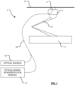
- FIG. 1 a schematic representation of the monitoring system 1.
- the system comprises a conducting block 3 and a carrier 7 (otherwise collectively known as a "pan head") for the block 3 that together form a current collector 5.
- the current collector 5 is coupled to a mechanism 9 for raising or lowering the carrier 7 and conducting block 3 with respect to an electric vehicle 11.
- the mechanism 9 is configured to urge the conducting block 3 into abutment, in this particular arrangement, with an overhead conducting line (OCL) 13 so that current may be drawn from the OCL 13 and supplied to the vehicle 11.
- OCL overhead conducting line
- the conducting block 3 can be of any suitable conducting material.
- the conducting block is - at least principally - of carbon.
- the conducting block 3 includes a plurality of sensor modules (not shown in Fig. 1 ) that are, in this particular arrangement, coupled in series to one another and to an optical source 15 and an optical signal interpretation module 17 by means of optical coupling means that comprises an optic fibre 19.
- the optical coupling means comprises a plurality of optic fibres with each said fibre of said plurality coupling a said sensor module of said plurality to the optical source 15 and the optical signal interpretation module 17.
- the optical source 15 comprises a broadband (i.e. wide spectrum) light source, for example a broadband LED light source.
- a broadband LED light source for example a broadband LED light source.
- the light source could comprise a narrow wavelength source, such as a laser light source, and in this configuration signals from respective sensor modules may be distinguished from one another on the basis of the time of flight of signals between the source and the modules, that is to say the time elapsed between illumination of the sensor modules by the source and the receipt of signals back from the individual sensor modules.
- the optical signal interpretation module 17 can have many different forms, but in one envisaged arrangement the module 17 comprises an optical signal analyser 21 coupled to the optic fibre 19, and a computing resource 23 such as a personal computer (PC) or equivalent.
- the computing resource includes an integral data store 25 for the storage of data, but it will be appreciated that the data store may be external to the module 17.
- the computing resource 23 is coupled to a position determination module 27 that may comprise a GPS device that is adapted to determine the position of the module (and hence any vehicle to which it is affixed) by triangulation using signals from satellites orbiting the earth.
- a position determination module 27 may comprise a GPS device that is adapted to determine the position of the module (and hence any vehicle to which it is affixed) by triangulation using signals from satellites orbiting the earth.
- Other position determination modules such as a module that implements dead-reckoning functionality, may instead be provided without departing from the scope of the invention.
- each array comprises a plurality of FBG sensors arranged in a geometric pattern.
- each array comprises three FBG sensors arranged in a triangle, referred to herein as a "rosette layout" of FBGs. This arrangement allows the correlation of adjacent FBGs, rather than the absolute (or differential) wavelength shift of a thermal FBG, for temperature compensation.
- a fibre that comprises nine FBG-based sensors which are arranged in three-sensor rosettes is integrated into each pan-head (for example, adhered to the pan-head so that the rosettes lie between the pan-head and the carbon collector) and connected to the interrogation unit for data logging.
- Figure 3 shows a typical rosette layout that avoids complex cable routing down the pantograph arm and allows adequate connection of the fibres to the interrogation system.
- each rosette includes three FBGs, each being sensitive to both strain (force caused) and temperature changes.
- S T 1 C T 13 ⁇ S T 3
- S F 1 C F 13 ⁇ S F 3
- C T13 and C F13 are the correlation coefficients of temperature and force sensitivities of the two FBGs, respectively
- Equation (4) the temperature induced wavelength shift is no longer included in the equation used for the calculation of the applied force F. In other words, temperature compensation has been successfully achieved.
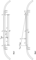
- three FBG sensor rosettes are integrated into the aluminium bottom of a pan-head at three different locations, labelled respectively left, central and right, as illustrated in Figure 4 .
- the areas which are covered with strain rosettes are spaced by 27 cm from the central rosette.
- the schematic diagram of the arrangement of three rosettes and the fibre routing on the pan-head is shown in Figure 2 .
- Figure 7 illustrates the forces that are acting on a pantograph.
- F static is measured using Equation (11) based on the data obtained from the FBG rosettes as described above.
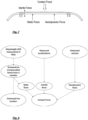
- the overall contact force measurement process can thus be summarized using a flow chart as shown in Figure 8 , showing the underpinning methodology used for the propriety software development for the contact force measurement.
- Equation (16) summarise the overall contact force calculation which consists of static force, inertial force and aerodynamic force:
- FIG. 9 shows a cross-comparison between the measured contact force of a pantograph with built-in sensors and closed-loop control, and the required contact force documented in BS EN 50367 when a train is running at different speeds. It is apparent from Fig. 9 that a very good agreement has been reached.
- the required contact force is derived from the standards document and is related to the speed of a train.
- the real time measured force is used as a feedback to the control valve in order to adjust the force to its required value.
- the control is using PID (proportional-integral-derivative) technique and the system continuously calculates an error value e ( t ) which is the difference between the required and measured contact forces and applies a correction based on proportional, integral, and derivative terms.
- the control system attempts to minimize the error over time by adjusting the input voltage of control valve wired to the pantograph.
- V ( t ) is the correction voltage of the control valve.
- K p , K i and K d are coefficients of the proportional, integral and derivative terms that are obtained through calibration.
- F aim is the required contact force. The difference between the aimed and measured forces, e ( t ), is thus reduced by varying the input voltage of the control valve.
- the flow chart of the control system is shown in Figure 10 .
- the system may include a position sensing module operable to determine the geographic position of the pantograph (so that any detected defects in the catenary can be logged).
- a position sensing module operable to determine the geographic position of the pantograph (so that any detected defects in the catenary can be logged).
Landscapes
- Engineering & Computer Science (AREA)
- Power Engineering (AREA)
- Transportation (AREA)
- Mechanical Engineering (AREA)
- Physics & Mathematics (AREA)
- General Physics & Mathematics (AREA)
- Current-Collector Devices For Electrically Propelled Vehicles (AREA)
- Measuring Temperature Or Quantity Of Heat (AREA)
- Optical Transform (AREA)
- Length Measuring Devices By Optical Means (AREA)
Description
- This invention relates to an optical monitoring system, in particular to a monitoring system that includes a plurality of optical sensor modules.
- In one envisaged implementation, the system disclosed may be utilised for monitoring a current collector, for example a collector of the type that is employed by an electric vehicle (such as a train or tram) to draw current from a conductor, for example an overhead conductor wire (known as a catenary) or a conducting rail. In other applications the teachings of the present invention may be employed to monitor other types of current collectors, for example current collectors employed in electrical motors and the like.
- The teachings of the present invention are provided below in the context of a monitoring system for an electric locomotive that includes a pantograph to draw current from an overhead catenary. It should be noted, however, that this particular application is merely one illustrative application of the teachings of the invention and that many other applications exist. As such, the following description should not be considered to be a limitation of the scope of the present invention to the particular application described hereafter in detail.
- The pantograph is a critical, roof-mounted part of a modern electric train, tram or bus that functions to collect current from an overhead catenary wire. Successful current collection requires a reliable pantograph-catenary contact with a steady force under all conditions, in particular against mechanical, dynamic and aerodynamic effects seen as the train travels along the line. Thus it is of critical importance to have real-time information of the contact conditions between the pantograph and catenary when the train is in operation. The contact force at the interface of pantograph-catenary varies as a function of speed and is documented in industrial standards, for example British Standard BS EN 50367.
- However, the contact force must be steady to provide acceptable current-collecting efficiency. If the contact force is lower than that required, there is a power loss, for example, in the form of electric arcs. The high rate of arcing and continuous sparking can induce strong electromagnetic noise in the environment as well as electricity-induced wear. If the contact force is higher than that required, wear of the carbon blocks carried by the pantograph becomes an important issue due to the increased mechanical friction, thus resulting in a shortened lifetime of the pantograph.
- As a consequence, the rail industry (in particular) is keen to be able to monitor the contact condition of the pantograph against catenary. However, technical challenges arise, inter alia, from the pantograph's harsh working conditions as the pantograph is powered at 25kV and trains can move at speeds of up to 350 km/h. Also, the high electromagnetic interference requires any instruments installed for measurement to be appropriately insulated, which tends to make the whole system more complex due to the added mass and the measurement error contributed by the added instrumentation.
- More recently optic fibre based sensors have shown significant advantages over previously proposed electrical sensors, due to their intrinsic insulator nature and their small size and light weight - which renders them suitable for being integrated or retrofitted into the pantograph for non-invasive remote condition monitoring.
- Two types of optical fibre sensing systems have been widely reported for monitoring pantograph-catenary contact force, using either fibre Bragg grating (FBG) based or interferometric based approaches. The FBG-based technique requires temperature compensation, when it is used for strain/force measurement as FBGs are sensitive to both strain and temperature. As a result, a significant amount of research effort has been focused on temperature compensation schemes in order to achieve an accurate measurement of the contact condition at the pantograph-catenary interface.
- Camolli et al reported the use of two fibres (see: L. Comolli, G. Bucca, M. Bocciolone and A. Collina. 2008. First results from in-line strain measurements with FBG sensors on the pantograph collector of underground trains. Proceeding of SPIE. Vol. 7726), each carrying a single FBG only, for the pantograph contact force measurement, with one FBG being used for strain measurement and the other for temperature compensation. The FBG sensor for temperature compensation is mounted in an orthogonal direction to that for strain measurement and at a position where the strain values are the lowest. This approach is based on the assumption that the temperature distribution in the carbon collector block is uniform along the pan-head, but as this is not true in reality this approach will likely lead to inaccurate readings.
- Wagner et al reported the use of an aluminium box (see: R. Wagner, D. Maicz, W. Viel, F. Saliger, C. Saliger, R. Horak and T. Noack. 2014. A fibre optic sensor instrumented pantograph as part of a continuous structural health monitoring system for railway overhead lines. 7th European Workshop on Structural Health Monitoring ) not just for protecting the FBG sensors from the harsh environment, but also for confining three FBG sensors within a small footprint (box), with one free FBG (strain-free) being used for temperature measurement/compensation and the other two for strain measurement. Each pantograph pan head is provided with two aluminium boxes, and as each pantograph typically includes two pan heads there are therefore 12 FBG sensors that need to be connected to the interrogation equipment using 4 fibre patch leads. This complexity aside, the proposal is disadvantageous as the addition of 4 aluminium boxes to the pan-heads of the pantograph increases the mass of the pan-heads and hence the aerodynamic force when a train moves at a high speed.
- European Patent No.
EP 1975584 discloses the use of two FBGs in a "push-pull" configuration with one being configured in a 'tensile' condition and the other in 'compression' when the contact force is applied. The acting force can thus be determined by cancelling out the temperature effect and doubling the strain measurement sensitivity. However, this is only valid when the two FBGs are subject to the same temperature effects, which is not necessarily true in reality. -
WO2014072436 A1 ,US6125216A andWO 2006107278 A1 reveal further monitoring systems for electric vehicles drawing current from a conductor by means of a current collector which employ fibre Bragg grating sensors (FBG sensors). - All the previously proposed FBG-based techniques described above have either used the absolute wavelength shift of a thermal grating or their differential value to measure temperature for compensation. However, these approaches have been shown to be ineffective inter alia for the following reasons:
- The temperature sensitivity of an FBG integrated into a pantograph is ~30pm/°C (for a free FBG, it is ~10pm/°C but it is not very practical) and is approximately 30 times higher than that of its strain/force sensitivity (which is ~1pm/N). As a result, the Bragg wavelength shift of a FBG caused by a temperature change of 1°C is roughly equivalent to that of ~30 N in force.
- The static contact force at low speed is around 90 N, therefore the wavelength shift induced by contact force is equivalent to that of a 3°C temperature variation. In reality, there is a wide temperature variation, ranging from -30°C to +45°C. As a consequence, the received strain/force signal tends to be overwhelmed by the 'noise'(temperature) signal.
- In reality, it is technically challenging (and potentially impossible) to use the absolute or differential wavelength shift compensation method to achieve effective temperature compensation as the temperature measurement error is required to be within ±3°C - a level of accuracy that is difficult to attain using thermocouples as references for calibration and a typical swept-laser based FBG interrogator with a resolution of ±2pm.
- International
PCT Patent Application No. WO2014072436 discloses an optical monitoring system for a pantograph when each sensor module of the system includes a strain-isolated FBG sensor and an FBG sensor that is responsive to both temperature and strain. Signals from the strain-isolated sensor can then be used to compensate for temperature. -
US Patent No. 6125216 discloses another strain-isolated FBG sensor that can be used, in common with the arrangement disclosed inWO2014072436 , to compensate for temperature in FBG sensors that are responsive to both temperature and strain. - The present invention has been devised with the foregoing problems in mind. The invention is limited by the appended independent claim.
- Various aspects of the teachings of the present invention, and arrangements embodying those teachings, will hereafter be described by way of illustrative example with reference to the accompanying drawings, in which:
-
Fig. 1 is a schematic representation of a monitoring system implementing the teachings of the present invention; -
Fig. 2 is a schematic representation of an optical signal interpretation module and optional attached components; -
Fig. 3 is a schematic representation of a preferred FBG arrangement; -
Fig. 4 is a schematic illustration of a preferred FBG layout; -
Fig. 5 is a schematic representation of the static force applied to a pan-head of a pantograph; -
Fig. 6 schematically represents the relationship between the force measured by an FBG array versus the distance between the array and the applied force; -
Fig. 7 is an illustration of the different forces acting on a pantograph; -
Fig. 8 is a flowchart illustrating the development of contact force measurement software; -
Fig. 9 is a graph of measured force versus mean contact force documented in BS EN 50367; and -
Fig. 10 is a chart depicting a closed-loop pantograph control system. - Illustrative implementations of the teachings of the present invention will now be provided, and particular reference will be made to a monitoring system for an electric locomotive that includes a pantograph to draw current from an overhead conductor. As aforementioned, it should however be noted that this particular application is merely one illustrative application of the teachings of the invention and that many other applications exist. As such, the following description should not be considered to be a limitation of the scope of the present invention to the particular application that is described hereafter in detail.
- With this proviso in mind, reference will now be made to
Fig. 1 in which there is depicted a schematic representation of themonitoring system 1. The system comprises a conductingblock 3 and a carrier 7 (otherwise collectively known as a "pan head") for theblock 3 that together form a current collector 5. - The current collector 5 is coupled to a
mechanism 9 for raising or lowering the carrier 7 and conductingblock 3 with respect to anelectric vehicle 11. Themechanism 9 is configured to urge the conductingblock 3 into abutment, in this particular arrangement, with an overhead conducting line (OCL) 13 so that current may be drawn from theOCL 13 and supplied to thevehicle 11. - The conducting
block 3 can be of any suitable conducting material. For example, in one envisaged arrangement the conducting block is - at least principally - of carbon. The conductingblock 3 includes a plurality of sensor modules (not shown inFig. 1 ) that are, in this particular arrangement, coupled in series to one another and to anoptical source 15 and an opticalsignal interpretation module 17 by means of optical coupling means that comprises anoptic fibre 19. - In another envisaged implementation the optical coupling means comprises a plurality of optic fibres with each said fibre of said plurality coupling a said sensor module of said plurality to the
optical source 15 and the opticalsignal interpretation module 17. - In a preferred implementation, the
optical source 15 comprises a broadband (i.e. wide spectrum) light source, for example a broadband LED light source. This arrangement is particularly preferred as it enables individual sensor modules to be tuned to respond to illumination by the source by emitting signals in a wavelength band distinct from those allocated to other sensor modules. In another envisaged implementation the light source could comprise a narrow wavelength source, such as a laser light source, and in this configuration signals from respective sensor modules may be distinguished from one another on the basis of the time of flight of signals between the source and the modules, that is to say the time elapsed between illumination of the sensor modules by the source and the receipt of signals back from the individual sensor modules. - Referring now to
Fig. 2 , the opticalsignal interpretation module 17 can have many different forms, but in one envisaged arrangement themodule 17 comprises anoptical signal analyser 21 coupled to theoptic fibre 19, and acomputing resource 23 such as a personal computer (PC) or equivalent. In the arrangement depicted inFig. 2 , the computing resource includes anintegral data store 25 for the storage of data, but it will be appreciated that the data store may be external to themodule 17. - In a particularly preferred arrangement, the
computing resource 23 is coupled to aposition determination module 27 that may comprise a GPS device that is adapted to determine the position of the module (and hence any vehicle to which it is affixed) by triangulation using signals from satellites orbiting the earth. Other position determination modules, such as a module that implements dead-reckoning functionality, may instead be provided without departing from the scope of the invention. - The presently preferred embodiment of the invention addresses the disadvantages described above by providing a plurality of discrete FBG sensor arrays, where each array comprises a plurality of FBG sensors arranged in a geometric pattern. According to the invention, each array comprises three FBG sensors arranged in a triangle, referred to herein as a "rosette layout" of FBGs. This arrangement allows the correlation of adjacent FBGs, rather than the absolute (or differential) wavelength shift of a thermal FBG, for temperature compensation.
- In the preferred embodiment a fibre that comprises nine FBG-based sensors which are arranged in three-sensor rosettes is integrated into each pan-head (for example, adhered to the pan-head so that the rosettes lie between the pan-head and the carbon collector) and connected to the interrogation unit for data logging.
Figure 3 shows a typical rosette layout that avoids complex cable routing down the pantograph arm and allows adequate connection of the fibres to the interrogation system. - The sensors are arranged in a common plane (i.e. laid flat on the pan-head of the pantograph) at an angle of approximately 60° to one another as a part of each so-called sensor rosette. In this embodiment, each rosette includes three FBGs, each being sensitive to both strain (force caused) and temperature changes.
- In this particular arrangement, the corresponding wavelength shift Δλi of FBG i (i=1, 2, 3) can be given by:

- With reference to
Figure 3 , if a force is applied perpendicular to FBG3, the force sensitivity experienced by FBG3 will be different to that experienced by FBG1 and FBG2. However, their temperature performance (trend) will be similar on account of their relative proximity to one another (as evidenced in the abundance of data that we have collected experimentally). Thus Equation (1) can be further expanded as follows:
FBGs 

- As is indicated clearly in Equation (4), the temperature induced wavelength shift is no longer included in the equation used for the calculation of the applied force F. In other words, temperature compensation has been successfully achieved.
- In order to provide accurate information of the contact force and contact location of the pantograph against the catenary, three FBG sensor rosettes are integrated into the aluminium bottom of a pan-head at three different locations, labelled respectively left, central and right, as illustrated in
Figure 4 . In the preferred arrangement, the areas which are covered with strain rosettes are spaced by 27 cm from the central rosette. The schematic diagram of the arrangement of three rosettes and the fibre routing on the pan-head is shown inFigure 2 . - When a static force, Fstatic, is applied on the pan-head, the contact force that each rosette 'senses' is termed Fl, Fc and Fr respectively as shown in
Figure 5 and each can be expressed using Equation (4), with temperature effects having been fully compensated. The distance of the overhead wire with reference to these three rosettes can thus be labelled xl , xc and xr , as illustrated inFigure 5 . - The contact force measured by each rosette, however, is linearly proportional to its distance to the location of the static force applied. As illustrated in
Figure 6 , when the static force is applied on top of the left rosette, the left rosette measured force is equal to the static force (Flmax = Fstatic ). However, when the static contact force moves to the right side, Fl will decrease linearly until it reaches Flmin = 0 when the overhead line is located on top of right sensor rosette. This relationship, as shown inFigure 6 , can be described as follows:


- During operation of the train, the overhead line tends to be primarily located in the central region of the pan-head. Therefore, it is proposed to use the central rosette to measure the static force applied, based on the location information derived from Equations (7) and (8). If the static force is applied on the left zone, i.e. xl ≤ Dlr /2, xc is given by:


-
Figure 7 illustrates the forces that are acting on a pantograph. The contact force comprises the vertical static force, the inertial forces and the aerodynamic force and thus can be expressed using the following formula, defined in BS EN 50317 [14]:
- Fstatic is measured using Equation (11) based on the data obtained from the FBG rosettes as described above. Finertial can be measured using FBG accelerometers, which can be installed into the support springs of the pan-head to capture the dynamic displacement of the pan-head. Based on the measured acceleration and the mass of the pan-head, the inertial force can be calculated as follows:


- Faero is velocity-dependent and can be estimated by:

- The overall contact force measurement process can thus be summarized using a flow chart as shown in
Figure 8 , showing the underpinning methodology used for the propriety software development for the contact force measurement. - Equation (16) summarise the overall contact force calculation which consists of static force, inertial force and aerodynamic force:

- The novel sensing approach described above has enabled real-time measurement and the measurement data obtained would facilitate a closed-loop control of the pantograph, both to avoid extreme scenarios (such as dewirement) occurring and to maintain a contact force required and documented in industrial standards for power efficiency. To illustrate its effectiveness,
Figure 9 shows a cross-comparison between the measured contact force of a pantograph with built-in sensors and closed-loop control, and the required contact force documented inBS EN 50367 when a train is running at different speeds. It is apparent fromFig. 9 that a very good agreement has been reached. - The required contact force is derived from the standards document and is related to the speed of a train. The real time measured force is used as a feedback to the control valve in order to adjust the force to its required value. The control is using PID (proportional-integral-derivative) technique and the system continuously calculates an error value e(t) which is the difference between the required and measured contact forces and applies a correction based on proportional, integral, and derivative terms. The control system attempts to minimize the error over time by adjusting the input voltage of control valve wired to the pantograph. The PID system can be descried as:


Figure 10 . - It will be apparent from the foregoing that the teachings of the present invention provide an enhanced optical monitoring system that addresses drawbacks associated with previously proposed systems. The system may include a position sensing module operable to determine the geographic position of the pantograph (so that any detected defects in the catenary can be logged). A variety of additional enhancements will be apparent to persons of ordinary skill in the art.
- It will be appreciated that whilst various aspects and embodiments of the present invention have heretofore been described, the scope of the present invention is not limited to the particular arrangements set out herein and instead extends to encompass all arrangements, and modifications and alterations thereto, which fall within the scope of the invention as defined by the claims.
In addition, whilst embodiments of the present invention have been described above in the context of software modules that are executable by a processor, it should be noted that the scope of the present invention is not limited to an implementation of the teachings of the invention in software. Rather, the skilled person will immediately appreciate that the functionality described herein may equally be implemented in hardware (for example, by means of a plurality of application specific integrated circuits (ASICS)) or, indeed, by a mix of hardware and software.
Claims (15)
- A monitoring system (1) for an electric vehicle (11) that draws current from a conductor by means of a current collector (3) that contacts a conductor (13) in operation of the vehicle, the system comprising:a plurality of sensor modules configured to be distributed at spaced intervals throughout the current collector, wherein each sensor module comprises three FBG sensors, that is Fibre Bragg Grating sensors (FBG1 to FBG9), arranged in a common plane and configured to be laid flat on a pan head of a pantograph, each said module (FBG1-3; FBG4-6; FBG7-9) being comprised only of FBG sensors that are responsive in use to both temperature and strain, wherein the sensors of each said module are in close proximity to one another so that temperature performance of the sensors is similar and are arranged in a triangular pattern with an angle of approximately 60 degrees between adjacent sensors so that temperature induced wavelength changes in the FBG sensors of each module can be compensated for;an optical source (15) for illuminating each said sensor module;means (19) for optically coupling said optical source (15) to each said sensor module; andan optical signal interpretation module (17) configured to receive optical signals from each said sensor module via said optical coupling means, said optical signals being generated by said sensor modules in response to illumination of said sensor modules by said optical source, said interpretation module being configured to be capable of mathematically correlating optical signals from at least two sensors in each sensor module to compensate for temperature induced wavelength changes in the FBG sensors of each module and thereby provide a temperature-independent strain measurement for each said sensor module.
- A system according to Claim 1, wherein said interpretation module (17) is further configured to be capable of determining the position of the conductor relative to the surface of the current collector that contacts said conductor.
- A system according to any preceding claim, the said system comprising the said current collector, wherein the current collector comprises a support (7) and a conductor block (3) mounted thereon, the conductor block being arranged to contact the conductor in operation of the vehicle.
- A system according to Claim 3, wherein the support (7) comprises a pan head.
- A system according to Claim 3 or 4, wherein said conductor block is of Carbon.
- A system according to any of claims 3 to 5, wherein said sensor modules are provided between said support (7) and conductor block (3) of said current collector.
- A system according to Claim 6, wherein a first of said three sensor modules is roughly centrally located within said current collector, and a second and a third of said three sensor modules are located to either side of said centrally located first module.
- A system according to any preceding claim, further comprising a position determining module (27) for determining the geographical position of the electric vehicle.
- A system according to Claim 8, wherein said position determining module (27) comprises a GPS module.
- A system according to any preceding claim, further comprising means for storing data (25), said means for storing data being configured to store one or more of: temperature data, strain data, conductor position data and vehicle position data.
- A system according to any preceding claim, wherein said optical coupling means comprises a plurality of optic fibres, each fibre of said plurality being coupled one of said sensor modules.
- A system according to any of Claims 1 to 10, wherein said optical coupling means comprises an optic fibre (19), said sensor modules being optically coupled together and to said source by said optic fibre.
- A system according to Claim 12, wherein said signal interpretation module is configured to distinguish between individual sensor modules of said plurality on the basis of the time between illuminating said sensor modules with said source and the time of receipt of signals from each said module.
- A system according to Claim 12, wherein each said sensor module is configured to generate a response in a predetermined unique wavelength/frequency range and said signal interpretation module is configured to distinguish between signals from respective sensor modules by determining in which said wavelength/frequency range said signals fall.
- A system according to Claim 3 and facultatively to any of Claims 4-14 further comprising a processor (23) operable to determine the strain applied to said current collector, said processor being coupled - in a feedback loop - to means operable to increase or decrease the extent to which said current collector bears upon said conductor.
Applications Claiming Priority (2)
| Application Number | Priority Date | Filing Date | Title |
|---|---|---|---|
| GBGB1700573.7A GB201700573D0 (en) | 2017-01-12 | 2017-01-12 | Optical monitoring system |
| PCT/EP2018/025006 WO2018130427A2 (en) | 2017-01-12 | 2018-01-12 | Optical monitoring system |
Publications (3)
| Publication Number | Publication Date |
|---|---|
| EP3568312A2 EP3568312A2 (en) | 2019-11-20 |
| EP3568312C0 EP3568312C0 (en) | 2023-12-27 |
| EP3568312B1 true EP3568312B1 (en) | 2023-12-27 |
Family
ID=58463298
Family Applications (1)
| Application Number | Title | Priority Date | Filing Date |
|---|---|---|---|
| EP18709259.8A Active EP3568312B1 (en) | 2017-01-12 | 2018-01-12 | Optical monitoring system |
Country Status (6)
| Country | Link |
|---|---|
| US (1) | US11385110B2 (en) |
| EP (1) | EP3568312B1 (en) |
| CN (1) | CN110382284A (en) |
| ES (1) | ES2971039T3 (en) |
| GB (2) | GB201700573D0 (en) |
| WO (1) | WO2018130427A2 (en) |
Families Citing this family (4)
| Publication number | Priority date | Publication date | Assignee | Title |
|---|---|---|---|---|
| US20220204061A1 (en) * | 2012-08-10 | 2022-06-30 | Transportation Ip Holdings, Llc | Examining system and method |
| US10807621B2 (en) * | 2017-01-23 | 2020-10-20 | Broadsens Corp. | Train pantograph structural health monitoring system |
| CN110514131B (en) * | 2019-08-26 | 2021-01-19 | 西安交通大学 | Intelligent layered fiber grating two-dimensional strain sensor |
| CN113049152A (en) * | 2021-03-01 | 2021-06-29 | 深圳市简测智能技术有限公司 | Pantograph dynamic contact force monitoring system and method |
Family Cites Families (14)
| Publication number | Priority date | Publication date | Assignee | Title |
|---|---|---|---|---|
| DE19725906C1 (en) * | 1997-06-13 | 1999-02-18 | Abb Daimler Benz Transp | Device for measuring the contact pressure on a pantograph |
| GB2326471B (en) * | 1997-06-19 | 2001-05-30 | British Aerospace | A strain isolated optical fibre bragg grating sensor |
| GB9824756D0 (en) * | 1998-11-11 | 1999-01-06 | Europ Economic Community | A strain sensor and strain sensing apparatus |
| GB2408570B (en) | 2003-10-31 | 2005-11-23 | Morganite Elect Carbon | Monitoring system for electrical vehicles drawing current from overhead conductors |
| FR2864202B1 (en) * | 2003-12-22 | 2006-08-04 | Commissariat Energie Atomique | INSTRUMENT TUBULAR DEVICE FOR TRANSPORTING A PRESSURIZED FLUID |
| WO2006107278A1 (en) * | 2005-04-05 | 2006-10-12 | Agency For Science, Technology And Research | Fiber bragg grating sensor |
| GB0508574D0 (en) * | 2005-04-27 | 2005-06-01 | Morganite Elect Carbon | Monitoring system for electrical vehicles drawing current from conductors |
| DE102005024202A1 (en) * | 2005-05-25 | 2006-11-30 | Siemens Ag | Force measuring device and method for determining a contact force |
| DE102007015180A1 (en) | 2007-03-29 | 2008-10-09 | Siemens Ag | Force measuring cell, contact force measuring device and method for measuring a contact force between a current collector and a power line |
| CN102278947B (en) * | 2011-04-29 | 2013-04-24 | 大连理工大学 | Packaged FBG (Fiber Bragg Grating) sensor for strain and crack test of bituminous concrete road surface |
| GB2511473A (en) * | 2012-11-07 | 2014-09-10 | Univ City | Optical monitoring system |
| CN102944613B (en) * | 2012-11-16 | 2015-04-01 | 中国科学院半导体研究所 | Detecting and positioning system for optical fiber acoustic emission |
| FR3014200B1 (en) * | 2013-12-02 | 2017-05-26 | Commissariat Energie Atomique | CONTROL OF INDUSTRIAL STRUCTURE |
| DE102016014280B4 (en) * | 2016-11-30 | 2018-07-12 | Hottinger Baldwin Messtechnik Gmbh | Weldable FBG strain sensor assembly |
-
2017
- 2017-01-12 GB GBGB1700573.7A patent/GB201700573D0/en not_active Ceased
-
2018
- 2018-01-12 CN CN201880006886.7A patent/CN110382284A/en active Pending
- 2018-01-12 ES ES18709259T patent/ES2971039T3/en active Active
- 2018-01-12 WO PCT/EP2018/025006 patent/WO2018130427A2/en unknown
- 2018-01-12 GB GB1911494.1A patent/GB2572935B/en active Active
- 2018-01-12 EP EP18709259.8A patent/EP3568312B1/en active Active
- 2018-01-12 US US16/477,375 patent/US11385110B2/en active Active
Also Published As
| Publication number | Publication date |
|---|---|
| US20200055401A1 (en) | 2020-02-20 |
| WO2018130427A2 (en) | 2018-07-19 |
| GB2572935A (en) | 2019-10-16 |
| GB201911494D0 (en) | 2019-09-25 |
| EP3568312C0 (en) | 2023-12-27 |
| EP3568312A2 (en) | 2019-11-20 |
| CN110382284A (en) | 2019-10-25 |
| ES2971039T3 (en) | 2024-06-03 |
| US11385110B2 (en) | 2022-07-12 |
| WO2018130427A3 (en) | 2018-08-30 |
| GB201700573D0 (en) | 2017-03-01 |
| GB2572935B (en) | 2022-04-20 |
Similar Documents
| Publication | Publication Date | Title |
|---|---|---|
| EP3568312B1 (en) | Optical monitoring system | |
| JP7045235B2 (en) | Transport monitoring system | |
| EP3455594B1 (en) | Fiber-optic based traffic and infrastructure monitoring system | |
| Schröder et al. | An approach to continuous on-site monitoring of contact forces in current collectors by a fiber optic sensing system | |
| US10556605B2 (en) | Railway guide system including sensors fixed to a rail | |
| Boffi et al. | Optical fiber sensors to measure collector performance in the pantograph-catenary interaction | |
| CN113661385B (en) | Optical fiber sensor unit, optical measurement system, axle counting device and axle counting method | |
| CN102252627B (en) | Gauge detection device and detection method for high-speed railway track | |
| Gubaidullin et al. | Microwave-photonic sensory tire control system based on FBG | |
| JP4954733B2 (en) | Pantograph contact force measuring method and contact force measuring device | |
| JP2000230935A (en) | Accelerometer and acceleration-measuring apparatus equipped with the same | |
| Schröder et al. | Fibre optic sensing system for monitoring of current collectors and overhead contact lines of railways | |
| US9587995B2 (en) | Optical monitoring system | |
| CN105783777A (en) | Fiber grating sensing-based railway track line shape on-line monitoring device and method | |
| Comolli et al. | First results from in line strain measurements with FBG sensors on the pantograph collector of underground trains | |
| Bocciolone et al. | Comparison of optical and electrical measurements of the pantograph-catenary contact force | |
| Chen et al. | A temperature compensated fibre Bragg grating (FBG)-based sensor system for condition monitoring of electrified railway pantograph | |
| EP2092120B1 (en) | System for monitoring the subsidences of a ballast of a track over a great distance | |
| Ecke et al. | On-line characterization of impacts on electrical train current collectors using integrated optical fiber grating sensor network | |
| Bocciolone et al. | An application of FBG accelerometers for monitoring pantographs of underground trains | |
| Urakseev et al. | Fiber-optical sensor with an acousto-optical filter for monitoring the status of overhead power lines | |
| Laffont et al. | Innovative FBG sensing techniques for the railway industry: application to overhead contact line monitoring | |
| Boffi et al. | Fiber sensor for collector strain monitoring in the pantograph-catenary interaction | |
| Sun et al. | Optical fibre sensing: a solution for industry | |
| WO2024075153A1 (en) | Stake position change detection system and stake position change detection method |
Legal Events
| Date | Code | Title | Description |
|---|---|---|---|
| STAA | Information on the status of an ep patent application or granted ep patent |
Free format text: STATUS: UNKNOWN |
|
| STAA | Information on the status of an ep patent application or granted ep patent |
Free format text: STATUS: THE INTERNATIONAL PUBLICATION HAS BEEN MADE |
|
| PUAI | Public reference made under article 153(3) epc to a published international application that has entered the european phase |
Free format text: ORIGINAL CODE: 0009012 |
|
| STAA | Information on the status of an ep patent application or granted ep patent |
Free format text: STATUS: REQUEST FOR EXAMINATION WAS MADE |
|
| 17P | Request for examination filed |
Effective date: 20190812 |
|
| AK | Designated contracting states |
Kind code of ref document: A2 Designated state(s): AL AT BE BG CH CY CZ DE DK EE ES FI FR GB GR HR HU IE IS IT LI LT LU LV MC MK MT NL NO PL PT RO RS SE SI SK SM TR |
|
| AX | Request for extension of the european patent |
Extension state: BA ME |
|
| DAV | Request for validation of the european patent (deleted) | ||
| DAX | Request for extension of the european patent (deleted) | ||
| STAA | Information on the status of an ep patent application or granted ep patent |
Free format text: STATUS: EXAMINATION IS IN PROGRESS |
|
| STAA | Information on the status of an ep patent application or granted ep patent |
Free format text: STATUS: EXAMINATION IS IN PROGRESS |
|
| 17Q | First examination report despatched |
Effective date: 20211105 |
|
| GRAP | Despatch of communication of intention to grant a patent |
Free format text: ORIGINAL CODE: EPIDOSNIGR1 |
|
| STAA | Information on the status of an ep patent application or granted ep patent |
Free format text: STATUS: GRANT OF PATENT IS INTENDED |
|
| INTG | Intention to grant announced |
Effective date: 20230517 |
|
| GRAJ | Information related to disapproval of communication of intention to grant by the applicant or resumption of examination proceedings by the epo deleted |
Free format text: ORIGINAL CODE: EPIDOSDIGR1 |
|
| STAA | Information on the status of an ep patent application or granted ep patent |
Free format text: STATUS: EXAMINATION IS IN PROGRESS |
|
| INTC | Intention to grant announced (deleted) | ||
| GRAS | Grant fee paid |
Free format text: ORIGINAL CODE: EPIDOSNIGR3 |
|
| STAA | Information on the status of an ep patent application or granted ep patent |
Free format text: STATUS: GRANT OF PATENT IS INTENDED |
|
| GRAP | Despatch of communication of intention to grant a patent |
Free format text: ORIGINAL CODE: EPIDOSNIGR1 |
|
| GRAA | (expected) grant |
Free format text: ORIGINAL CODE: 0009210 |
|
| STAA | Information on the status of an ep patent application or granted ep patent |
Free format text: STATUS: THE PATENT HAS BEEN GRANTED |
|
| INTG | Intention to grant announced |
Effective date: 20231114 |
|
| AK | Designated contracting states |
Kind code of ref document: B1 Designated state(s): AL AT BE BG CH CY CZ DE DK EE ES FI FR GB GR HR HU IE IS IT LI LT LU LV MC MK MT NL NO PL PT RO RS SE SI SK SM TR |
|
| RAP3 | Party data changed (applicant data changed or rights of an application transferred) |
Owner name: CITY, UNIVERSITY OF LONDON |
|
| REG | Reference to a national code |
Ref country code: GB Ref legal event code: FG4D |
|
| REG | Reference to a national code |
Ref country code: CH Ref legal event code: EP |
|
| REG | Reference to a national code |
Ref country code: DE Ref legal event code: R096 Ref document number: 602018063163 Country of ref document: DE |
|
| REG | Reference to a national code |
Ref country code: IE Ref legal event code: FG4D |
|
| U01 | Request for unitary effect filed |
Effective date: 20240126 |
|
| U07 | Unitary effect registered |
Designated state(s): AT BE BG DE DK EE FI FR IT LT LU LV MT NL PT SE SI Effective date: 20240205 |
|
| PG25 | Lapsed in a contracting state [announced via postgrant information from national office to epo] |
Ref country code: GR Free format text: LAPSE BECAUSE OF FAILURE TO SUBMIT A TRANSLATION OF THE DESCRIPTION OR TO PAY THE FEE WITHIN THE PRESCRIBED TIME-LIMIT Effective date: 20240328 |
|
| PGFP | Annual fee paid to national office [announced via postgrant information from national office to epo] |
Ref country code: ES Payment date: 20240202 Year of fee payment: 7 |
|
| U20 | Renewal fee paid [unitary effect] |
Year of fee payment: 7 Effective date: 20240315 |
|
| PG25 | Lapsed in a contracting state [announced via postgrant information from national office to epo] |
Ref country code: GR Free format text: LAPSE BECAUSE OF FAILURE TO SUBMIT A TRANSLATION OF THE DESCRIPTION OR TO PAY THE FEE WITHIN THE PRESCRIBED TIME-LIMIT Effective date: 20240328 |
|
| PGFP | Annual fee paid to national office [announced via postgrant information from national office to epo] |
Ref country code: GB Payment date: 20240315 Year of fee payment: 7 |
|
| PG25 | Lapsed in a contracting state [announced via postgrant information from national office to epo] |
Ref country code: RS Free format text: LAPSE BECAUSE OF FAILURE TO SUBMIT A TRANSLATION OF THE DESCRIPTION OR TO PAY THE FEE WITHIN THE PRESCRIBED TIME-LIMIT Effective date: 20231227 Ref country code: NO Free format text: LAPSE BECAUSE OF FAILURE TO SUBMIT A TRANSLATION OF THE DESCRIPTION OR TO PAY THE FEE WITHIN THE PRESCRIBED TIME-LIMIT Effective date: 20240327 Ref country code: HR Free format text: LAPSE BECAUSE OF FAILURE TO SUBMIT A TRANSLATION OF THE DESCRIPTION OR TO PAY THE FEE WITHIN THE PRESCRIBED TIME-LIMIT Effective date: 20231227 |
|
| REG | Reference to a national code |
Ref country code: ES Ref legal event code: FG2A Ref document number: 2971039 Country of ref document: ES Kind code of ref document: T3 Effective date: 20240603 |
|
| PG25 | Lapsed in a contracting state [announced via postgrant information from national office to epo] |
Ref country code: IS Free format text: LAPSE BECAUSE OF FAILURE TO SUBMIT A TRANSLATION OF THE DESCRIPTION OR TO PAY THE FEE WITHIN THE PRESCRIBED TIME-LIMIT Effective date: 20240427 |
|
| PG25 | Lapsed in a contracting state [announced via postgrant information from national office to epo] |
Ref country code: CZ Free format text: LAPSE BECAUSE OF FAILURE TO SUBMIT A TRANSLATION OF THE DESCRIPTION OR TO PAY THE FEE WITHIN THE PRESCRIBED TIME-LIMIT Effective date: 20231227 |
|
| PG25 | Lapsed in a contracting state [announced via postgrant information from national office to epo] |
Ref country code: SK Free format text: LAPSE BECAUSE OF FAILURE TO SUBMIT A TRANSLATION OF THE DESCRIPTION OR TO PAY THE FEE WITHIN THE PRESCRIBED TIME-LIMIT Effective date: 20231227 |
|
| PG25 | Lapsed in a contracting state [announced via postgrant information from national office to epo] |
Ref country code: SM Free format text: LAPSE BECAUSE OF FAILURE TO SUBMIT A TRANSLATION OF THE DESCRIPTION OR TO PAY THE FEE WITHIN THE PRESCRIBED TIME-LIMIT Effective date: 20231227 Ref country code: SK Free format text: LAPSE BECAUSE OF FAILURE TO SUBMIT A TRANSLATION OF THE DESCRIPTION OR TO PAY THE FEE WITHIN THE PRESCRIBED TIME-LIMIT Effective date: 20231227 Ref country code: RO Free format text: LAPSE BECAUSE OF FAILURE TO SUBMIT A TRANSLATION OF THE DESCRIPTION OR TO PAY THE FEE WITHIN THE PRESCRIBED TIME-LIMIT Effective date: 20231227 Ref country code: IS Free format text: LAPSE BECAUSE OF FAILURE TO SUBMIT A TRANSLATION OF THE DESCRIPTION OR TO PAY THE FEE WITHIN THE PRESCRIBED TIME-LIMIT Effective date: 20240427 Ref country code: CZ Free format text: LAPSE BECAUSE OF FAILURE TO SUBMIT A TRANSLATION OF THE DESCRIPTION OR TO PAY THE FEE WITHIN THE PRESCRIBED TIME-LIMIT Effective date: 20231227 |
|
| PG25 | Lapsed in a contracting state [announced via postgrant information from national office to epo] |
Ref country code: PL Free format text: LAPSE BECAUSE OF FAILURE TO SUBMIT A TRANSLATION OF THE DESCRIPTION OR TO PAY THE FEE WITHIN THE PRESCRIBED TIME-LIMIT Effective date: 20231227 |
|
| PG25 | Lapsed in a contracting state [announced via postgrant information from national office to epo] |
Ref country code: PL Free format text: LAPSE BECAUSE OF FAILURE TO SUBMIT A TRANSLATION OF THE DESCRIPTION OR TO PAY THE FEE WITHIN THE PRESCRIBED TIME-LIMIT Effective date: 20231227 |
|
| REG | Reference to a national code |
Ref country code: CH Ref legal event code: PL |