EP3568065B1 - Physiologischer sensor für nahinfrarot-spektroskopie an verschiedenen tiefen - Google Patents
Physiologischer sensor für nahinfrarot-spektroskopie an verschiedenen tiefen Download PDFInfo
- Publication number
- EP3568065B1 EP3568065B1 EP18702747.9A EP18702747A EP3568065B1 EP 3568065 B1 EP3568065 B1 EP 3568065B1 EP 18702747 A EP18702747 A EP 18702747A EP 3568065 B1 EP3568065 B1 EP 3568065B1
- Authority
- EP
- European Patent Office
- Prior art keywords
- flexible
- receivers
- articulation
- elementary
- physiological sensor
- Prior art date
- Legal status (The legal status is an assumption and is not a legal conclusion. Google has not performed a legal analysis and makes no representation as to the accuracy of the status listed.)
- Active
Links
Images




Classifications
-
- A—HUMAN NECESSITIES
- A61—MEDICAL OR VETERINARY SCIENCE; HYGIENE
- A61B—DIAGNOSIS; SURGERY; IDENTIFICATION
- A61B5/00—Measuring for diagnostic purposes; Identification of persons
- A61B5/0059—Measuring for diagnostic purposes; Identification of persons using light, e.g. diagnosis by transillumination, diascopy, fluorescence
- A61B5/0075—Measuring for diagnostic purposes; Identification of persons using light, e.g. diagnosis by transillumination, diascopy, fluorescence by spectroscopy, i.e. measuring spectra, e.g. Raman spectroscopy, infrared absorption spectroscopy
-
- A—HUMAN NECESSITIES
- A61—MEDICAL OR VETERINARY SCIENCE; HYGIENE
- A61B—DIAGNOSIS; SURGERY; IDENTIFICATION
- A61B5/00—Measuring for diagnostic purposes; Identification of persons
- A61B5/02—Detecting, measuring or recording for evaluating the cardiovascular system, e.g. pulse, heart rate, blood pressure or blood flow
- A61B5/024—Measuring pulse rate or heart rate
- A61B5/02416—Measuring pulse rate or heart rate using photoplethysmograph signals, e.g. generated by infrared radiation
- A61B5/02427—Details of sensor
- A61B5/02433—Details of sensor for infrared radiation
-
- A—HUMAN NECESSITIES
- A61—MEDICAL OR VETERINARY SCIENCE; HYGIENE
- A61B—DIAGNOSIS; SURGERY; IDENTIFICATION
- A61B5/00—Measuring for diagnostic purposes; Identification of persons
- A61B5/02—Detecting, measuring or recording for evaluating the cardiovascular system, e.g. pulse, heart rate, blood pressure or blood flow
- A61B5/026—Measuring blood flow
- A61B5/0261—Measuring blood flow using optical means, e.g. infrared light
-
- A—HUMAN NECESSITIES
- A61—MEDICAL OR VETERINARY SCIENCE; HYGIENE
- A61B—DIAGNOSIS; SURGERY; IDENTIFICATION
- A61B2562/00—Details of sensors; Constructional details of sensor housings or probes; Accessories for sensors
- A61B2562/04—Arrangements of multiple sensors of the same type
- A61B2562/046—Arrangements of multiple sensors of the same type in a matrix array
Definitions
- the present invention relates to a physiological sensor for near-infrared spectroscopy, as well as to a near-infrared spectroscopy system comprising such a physiological sensor.
- the invention lies in the field of near-infrared spectroscopy for medical diagnostic applications and/or monitoring of physiological parameters.
- Near infrared spectroscopy is a classic technology in the medical field, which essentially consists of implementing, on the one hand, at least one transmitter emitting a beam of light in the near infrared, with a length between 650 and 1000 nanometers, which passes through organic tissues (unlike visible light and ultraviolet) and, on the other hand, at least one photosensitive receptor which measures the absorption and dispersion of photons having passed through organic tissues.
- the wavelengths used by the transmitter are chosen to be sensitive to these biological molecules (generally between 650 and 1000 nanometers), with oxyhemoglobin absorbing more wavelengths between 800 and 1000 nanometers while deoxyhemoglobin absorbs more wavelengths between 650 and 800 nanometers.
- the absorption of near-infrared light waves by oxyhemoglobin and deoxyhemoglobin serves in particular as a basis for calculating oxygen saturation in application of the Beer-Lambert law, which states that the concentration of a substance can be measured according to its degree of light absorption.
- the beam of photons emitted by a transmitter and received by a receiver takes the form of an arc of diffuse light which passes through organic tissues, where the penetration depth of the beam between the transmitter and the receiver corresponds to approximately one third of the distance between the transmitter and the receiver.
- the distance between transmitter and receiver has a considerable impact on the depth of penetration of the beam into organic tissues.
- a sufficiently large distance between the transmitter and the receiver is therefore necessary to ensure sufficient penetration which makes it possible to ensure measurement on deep layers and not on surface layers.
- the increase in this transmitter - receiver distance will have the effect of increased diffusion/absorption of the transmitted signal, resulting in reducing the spatial resolution of the measurement and attenuating the received signal.
- the spatial resolution of near-infrared spectroscopy does not exceed 0.5 millimeters immediately under the skin, and deteriorates with increasing depth.
- a known medical application of infrared spectroscopy is the measurement of brain activity or cerebral oximetry, by following the curves of oxyhemoglobin and deoxyhemoglobin concentrations at a given intracranial depth.
- a physiological sensor comprising a flexible strip on which are mounted a near-infrared beam transmitter and at least two near-infrared photosensitive receivers, including a proximal receiver separated by a proximal distance from the transmitter and a distal receiver separated by a distal distance from the transmitter which is greater than the proximal distance.
- the signal acquired by the proximal receptor comes from a more superficial (shallower) source and the signal acquired by the distal receiver includes this superficial zone but also a deeper component.
- This technique consisting of implementing a spatial subtraction of signals acquired by near-infrared spectroscopy at different depths, is also implemented for other applications, such as monitoring hemodynamic parameters or imaging vascular or blood volumes, as well as as described in the documents US 2016/0022223 , US 2013/0150726 And WO 2015/070162 .
- the document US 2016/0022223 for an application for monitoring hemodynamic parameters and the document US 2013/0150726 for an application for detecting a blood volume of the subcranial hematoma type each propose to place transmitters and receivers on a flexible support strip to be able to adapt the support strip to parts of the body of a patient, such as the skull or limb.
- the flexibility of the support band brings uncontrolled uncertainty to the relative positions between transmitters and receivers, thus harming the precision during spatial subtraction operations and therefore, ultimately, causing great inaccuracy in the results.
- the document WO 2015/070162 offers a physiological sensor comprising transmitters and receivers mounted on a rigid support plate, whether flat or curved.
- the rigidity of the support plate contributes to limiting the resolution.
- the transmitters and receivers are all in the same plane, so that some of them will not be pressed against the relevant part of the patient's body, in particular if this part is curved like a limb or a skull.
- a sensor is functionally limited in its applications by its own dimensions as to the depth of tissue that can be explored, as to its resolution and as to the skin or tissue surface on which it is applied.
- This sensor is, for example, unsuitable for monitoring cerebral activity or cerebral oximetry on the frontal hemispheres of a large panel of patients with variable cranial morphologies, because this sensor cannot be functionally applied to the roundness of the surface of the frontal hemispheres. Indeed, an air interface layer would appear between the skin surface and the sensor, which would represent a source of diffusion parasitizing the near-infrared beams, thus posing a problem of graphic modeling of the signal and the precision of the measurements.
- the present invention aims to resolve the aforementioned drawbacks, by proposing a solution for being able to carry out near-infrared spectroscopy at different depths with increased resolution and reliability in the measurements.
- Another aim of the invention is to offer a physiological sensor which makes it possible to carry out three-dimensional imaging with improved spatial resolution, for all parts of the body and in particular curved parts such as an internal organ (heart , liver, etc.), a limb (arm, leg) or a skull.
- curved parts such as an internal organ (heart , liver, etc.), a limb (arm, leg) or a skull.
- Another aim of the invention is to offer a physiological sensor that is portable and easily manipulated by medical personnel.
- Another aim of the invention is to enable near-infrared spectroscopy at different depths, which compensates for the variation in optical paths in the tissues crossed due to the variation in the roundness of the surfaces examined, and this by means of the same physiological sensor, with a view in particular to carrying out three-dimensional imaging with improved spatial resolution.
- the elementary modules - and therefore the transmitters and receivers - can be positioned on the relevant part of the patient's body to be analyzed (for example example a limb or an internal organ in a sanitized environment) in a precise, known and controlled manner, thus contributing to being able to adapt the shape of the physiological sensor as close as possible to the relevant part of the patient's body, while having precise control of the positioning and relative spacings between transmitters and receivers; such knowledge of these positions and spacings can then be injected into a precise and reliable calculation of spatial subtraction of signals acquired at different depths. This calculation can also take into account the angle of inclination of each joint to compensate for the distribution of light in biological tissues.
- Such a physiological sensor thus forms an optoelectronic layer or a layer of optoelectronic components (namely the transmitters and receivers) which can conform to the skin surface of any part of the patient's body, thanks to the joints, as well as to the morphology of the patient. the underlying organ, or the patient's organ, and allows the implementation of near-infrared spectroscopy to detect in vivo hemoglobins, which by nature only circulate in the vascular network.
- the joints between the elementary modules allow continuous or quasi-continuous contact of the optoelectronic components with the examination surface, without creating an intermediate air layer which is a source of light diffusion.
- each joint or angle of inclination between two elementary modules
- the angle sensors allowing precise and efficient processing to establish the spatial coordinates of the transmitters. and receivers of the different elementary modules.
- Such a physiological sensor thus provides a response to the problem of normalization of the processed signals, and of the necessary compensation of the variation of the optical paths, induced by the variation of roundness from one examination surface to another, with a view to a three-dimensional pictorial representation, in particular by using angle sensors which will effectively contribute to achieving increased and more reliable spatial resolution.
- At least one articulation between two elementary modules is a flexible articulation comprising a flexible strip configured for relative movement between the elementary modules by bending of the flexible strip.
- the relative movement between two elementary modules according to several angles of inclination is obtained by bending (in the manner of folding/unfolding) of the flexible strip forming the flexible joint connecting the two elementary modules.
- the optoelectronic layer composed of the assembly of elementary modules and joints, therefore forms a layer that is at least partly flexible or flexible and adjustable to the morphology of the surface to be analyzed thanks to the bending of the various flexible bands.
- a joint with a flexible band is thus called flexible or flexible, in the sense that it is adjustable in a continuous or non-discrete manner by bending of the flexible band, thus offering a multiplicity of angles of inclination.
- each articulation between two elementary modules is a flexible articulation comprising a flexible strip configured for relative movement between the elementary modules by bending of the flexible strip.
- all joints are flexible joints that flex to adapt to the morphology of the surface to be analyzed.
- each elementary module comprises a support, rigid or flexible, on which is arranged at least one optoelectronic component, and the flexible strip of the flexible articulation between two elementary modules is connected between the supports of said two elementary modules.
- the physiological sensor comprises a flexible membrane on which the optoelectronic components are arranged and distributed in islands delimiting the elementary modules, and where the flexible strip of the flexible articulation between two elementary modules is formed of a part of the flexible membrane extending between the islands delimiting said two elementary modules.
- the flexible membrane comprises at least one layer of elastomeric polymer in which the optoelectronic components are at least partially embedded.
- this flexible joint is coupled to an angle sensor comprising a flexible resistive sensor delivering measurement data reflecting a variation in resistance as a function of the bending of the flexible band
- the flexible joint is coupled to a flexible resistive sensor or flexion sensor.
- a technology is used to measure angles precisely, based on the exploitation of variations in resistance occurring when a conductive material is bent; the flexible resistive sensor behaves like a passive potentiometer whose resistance varies according to the deflection.
- the flexible resistive sensor is integrated into the flexible strip, in other words the flexible strip which forms the flexible articulation between two elementary modules integrates (internally or on the surface) such a flexible resistive sensor, by using a conductive material at the less partly embedded in the flexible strip or fixed on the surface on the flexible strip.
- the flexible resistive sensor is offset relative to the flexible strip, that is to say the flexible resistive sensor is not located on the flexible strip but is offset relative to this flexible strip on a offset part which will flex at the same time as or with the flexible band.
- the flexible resistive sensor will be able to indirectly measure the bending of the flexible strip by directly measuring the bending of this offset part.
- the flexible resistive sensors can thus be integrated into the flexible membrane described above, in particular by being offset to the sides of the flexible membrane.
- the flexible resistive sensor is integrated into a flexible blade fixed to the flexible strip, in particular in a detachable manner, so that a bending of the flexible strip leads to a bending of the flexible blade.
- the flexible resistive sensor comprises a conductive material at least partly embedded in the flexible blade or fixed on the surface on the flexible blade, and this flexible blade is attached to the flexible strip forming the flexible joint between two elementary modules.
- the flexible blade being attached to the flexible strip, the latter flexes with the flexible strip so that the measurement carried out by the flexible resistive sensor integrated into the flexible blade reflects the bending of the flexible strip and therefore delivers a measurement of the angle of inclination between the two elementary modules.
- the angle sensor function is provided on the flexible blade while the articulation function is provided by the flexible strip, thus dissociating the optoelectronic part (the optoelectronic components connected by the flexible joints) from the measurement part. angle (the angle sensors on the flexible blades).
- the physiological sensor comprises a flexible film on which flexible resistive sensors are arranged, where this flexible film is superimposed and fixed on the flexible membrane, and where this flexible film defines flexible blades superimposed or offset relative to the flexible strips of flexible joints between the elementary modules, the flexible resistive sensors being provided on these flexible blades.
- the flexible resistive sensors are provided on the flexible film which is itself attached to the flexible membrane receiving the optoelectronic components, thus dissociating the optoelectronic part (the flexible membrane) from the angle measuring part (the flexible film).
- the flexible film comprises at least one layer of elastomeric polymer in which the flexible resistive sensors are at least partially embedded.
- At least one articulation between two elementary modules is a semi-rigid articulation configured for relative movement between the elementary modules according to several discrete predefined inclination angles, where said semi-rigid articulation is configured to maintain a stable inclination between two elementary modules in each of said inclination angles, and to switch between two distinct inclination angles under the effect of a force applied to at least one of the two elementary modules concerned.
- Such a joint is semi-rigid, in the sense that, unlike the flexible band previously described, this semi-rigid joint is not adjustable continuously and without stability, but rather in a discreet manner with several angles of predefined inclination where, for each inclination angle, the joint maintains this inclination angle in a stable manner.
- a semi-rigid joint is provided with notches for adjusting the angle of inclination between the two elementary modules according to several predefined values.
- a semi-rigid joint is coupled to an angle sensor comprising electrical contactors, where each electrical contactor is coupled to an adjustment notch.
- each adjustment notch is coupled to a contactor, all of these contactors forming the angle sensor capable of establishing the measurement of the angle of inclination, each adjustment notch being in fact associated with an angle of inclination.
- a semi-rigid joint is coupled to an angle sensor produced in the form of a flexible resistive sensor attached to the joint and comprising a flexible blade which flexes with the joint, said flexible resistive sensor delivering measurement data reflecting a variation in resistance as a function of the bending of the flexible blade.
- each joint (whether it is a flexible joint or a semi-rigid joint) is adjustable between - 30 and + 30 degrees for the angle of inclination between the two elementary modules.
- each semi-rigid joint is adjustable according to several predefined inclination angles separated in pairs by a constant angular pitch, in particular an angular pitch of between 5 and 15 degrees.
- each semi-rigid joint can have the following inclination angles, in degrees, [0, 5, 10, 15, 20, 25, 30] or [0, 10, 20, 30] or [0, 15, 30].
- each semi-rigid joint comprises several balls cooperating with an elastic thrust element, said balls being movable in a curved rail of a predefined curvature and sliding inside a guide of the same curvature, and comprises in addition on the guide a slider capable of crushing the balls according to the sliding of the rail within the guide, where the supports linked by the articulation are respectively fixed to one end of the rail and to one end of the guide.
- such a semi-rigid joint comprises a rail sliding in a guide, with the balls and the elastic thrust element on the rail.
- the rail and the guide abutting one another represent an angle sector corresponding substantially to half of the possible inclination angle sector.
- the slider of the guide can establish electrical contact with the crushed ball corresponding to the sliding of the rail in the guide, thus making it possible to establish the angle of inclination.
- each semi-rigid joint comprises two solid hinge half-faces, of approximately half of the desired maximum inclination angle sector and having complementary reliefs which fit together when said hinge half-faces are pressed against each other. one against the other.
- These hinge half-faces are able to slide against each other in a controlled manner by applying a suitable force, so that these hinge half-faces deviate slightly to move from one adjustment notch to the next adjustment notch.
- a contactor can make it possible to know the position of the adjustment notch.
- the elementary modules are distributed in several lines and in several columns orthogonal to the lines.
- Such a distribution into rows and columns is advantageous for processing using a spatial subtraction method.
- each elementary module comprises a support, rigid or flexible, on which is arranged at least one optoelectronic component, and each support comprises two opposite and parallel longitudinal edges, and two opposite and parallel transverse edges, and each articulation connects either two contiguous transverse edges of two adjacent respective supports, or two contiguous longitudinal edges of two adjacent respective supports.
- each articulation between two elementary modules is a pivoting articulation around an articulation axis extending in the main plane; this pivoting being obtained by bending (or folding) of the flexible band of the flexible joint, or is obtained by pivoting between two discrete angles of inclination of the semi-rigid joint.
- the invention therefore relates to a near-infrared spectroscopy system, comprising a physiological sensor as described above, and further comprising a control unit configured to establish the spatial coordinates of each transmitter and each receiver as a function of the inclination angles of the joints, where said control unit is connected, on the one hand, to the transmitters of the physiological sensor to activate said transmitters individually and not concomitantly according to a predefined sequence and, on the other hand, to the receivers of the sensor physiological for recovery and three-dimensional processing of measurements from the receivers during said sequence as a function of the spatial coordinates of the transmitters and receivers, and in which the control unit is connected to each angle sensor to establish the spatial coordinates of each transmitter and each receiver as a function of the measurement data from said angle sensors.
- Such a spectroscopy system is particularly suitable for all parts of the body, including the limbs and internal organs (such as the heart) thanks to the conformation of the physiological sensor, and thanks to the control unit which makes it possible to activate the transmitters according to a predefined sequence and recover the measurements from the receivers.
- the control unit will take into consideration certain transmitters (such as for example pairs of transmitters aligned with the activated transmitter) and will not take into account certain other transmitters (in particular those located above beyond a predefined threshold distance).
- the processing of measurements from the receivers is a so-called three-dimensional processing insofar as it provides an in-depth result of the part of the body analyzed.
- control unit is configured for three-dimensional processing of the measurements from the receivers during the sequence according to a spatial subtraction method, or according to a tomography method with establishment of contrast maps, or even using a point cloud reconstruction method.
- the spatial subtraction method implements subtractions between measurements from selected receivers.
- the tomography method is obtained for example by establishing contrast maps at different wavelengths.
- the point cloud reconstruction method implements a consideration of all the absorption values by each receiver at each wavelength as constituting a point cloud. Then, a reconstruction algorithm (such as for example a machine learning classification algorithm) will make it possible to identify a coherence linked to the different volumes of homogeneous absorption, in order to allow a graphical representation, in other words this reconstruction algorithm will be applied to the set of points acquired over time in order to better distinguish the areas characterized by the measurement technique.
- a certainty coefficient could be assigned to highly repetitive points, which would make it possible to remove ambiguities in the measurement during an acquisition noisy by the movement of the patient, for example.
- control unit is configured to process according to three-dimensional processing (eg according to a spatial subtraction method, a tomography method, or a point cloud reconstruction method), each time a transmitter is activated. , only measurements from receivers selected according to a relative location with respect to said activated transmitter established from their spatial coordinates.
- three-dimensional processing eg according to a spatial subtraction method, a tomography method, or a point cloud reconstruction method
- the elementary modules are distributed in several lines and in several columns orthogonal to the lines, and the control unit is configured to process according to a spatial subtraction method, at each activation of a transmitter, the measurements coming from receivers arranged in the same row and in the same column as said transmitter.
- control unit configured to process, using a spatial subtraction method, each time a transmitter is activated, the measurements from receivers also arranged in a row and in a column different from those of said transmitter. .
- the three-dimensional processing of the measurements from the receivers during the sequence implements a spatial subtraction method, or a tomography method with establishment of contrast maps, or a point cloud reconstruction method.
- the recovery and treatment step is followed by a step of constructing a three-dimensional image representing the underlying tissue strata, and in particular a vascular or blood volume in an analysis volume, said vascular or blood volume being composed of voxels constructed from the three-dimensional processing of measurements from the receptors during the sequence.
- activation step and the recovery and processing step can be repeated at successive time intervals, in order to allow dynamic processing over time to monitor developments in real time.
- the step of establishing the spatial coordinates results in the generation of a three-dimensional and virtual optoelectronic imprint of the physiological sensor in the situation.
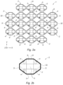
- the physiological sensor 1 comprises a plurality of elementary modules 2 (or elementary optoelectronic modules) connected together to form a flexible or articulated optoelectronic layer.
- a physiological sensor 1 can comprise at least ten elementary modules 2, and in particular at least twenty elementary modules 2; the number of elementary modules 2 being linked to the surface area of the zone to be analyzed.
- Each elementary module 2 is provided with a support 3 (rigid or flexible), made at least partially in a rigid or flexible material, such as a plastic, polymeric, elastomeric, composite or metallic material.
- the support 3 may have a general polygonal shape, and in particular a triangular, square, rectangular, hexagonal, octagonal shape, etc. In the examples illustrated on the figures 1a to 3b , the support 3 has a general octagonal shape. In the example of figures 8a and 8b , the support 3 has a general hexagonal shape.
- Each support 3 of an elementary module is connected to the support 3 of at least one adjacent elementary module by means of an articulation 6 between the two supports 3.
- each joint 6 is a pivoting joint around a joint axis extending in the main plane PP.
- the main plane PP corresponds to the plane (X, Y) defined by a longitudinal axis X and a transverse axis Y orthogonal to the longitudinal axis X; there is also represented a vertical axis Z orthogonal to the main plane PP or (X, Y).
- each joint 6 is a flexible joint comprising a flexible band joining the two supports 3 concerned, where the flexible band is adapted to flex and thus to allow continuous adjustment of the angle of inclination between the two brackets 3; this adjustment being continuous in the sense that the angle of inclination can vary continuously, that is to say non-discretely, by bending (yes folding) of the flexible strip.
- a flexible strip is made at least partially from a flexible material and in particular an elastomer.
- this flexible joint 6 is pivotable by bending or folding of the flexible strip, which flexes around a bend line (or fold line) which forms the hinge axis.
- the physiological sensor 1 naturally matches the part of the patient's body.
- this physiological sensor 1 is based on a flexible or flexible sheet (or matrix) of elementary modules 2 which can conform to the part of the patient's body to be analyzed, and in particular to the skin surface as well as to the morphology of the patient. the underlying organ.
- the physiological sensor 1 comprises a flexible membrane 300 on which the optoelectronic components 4, 5 are arranged and distributed in islands delimiting the elementary modules 2, where the flexible membrane 300 can comprise at least one elastomeric polymer layer in which the optoelectronic components 4, 5 are at least partially embedded.
- the flexible bands of the flexible joints correspond to the parts of the flexible membrane 300 located between the islands delimiting the elementary modules 2, and the supports of the elementary modules 2 correspond to the islands or parts of the flexible membrane 300 on which the or optoelectronic components 4, 5.
- each joint 6 is a semi-rigid joint which allows several angles of inclination, so that the angle of inclination between two supports 3 is adjustable in a discrete manner in steps or no angles d inclination determined.
- a semi-rigid joint 6 is configured to maintain a stable inclination between two supports 3 according to the discrete inclination angles offered by this semi-rigid joint 6.
- a semi-rigid joint 6 can switch between two distinct angles of inclination under the effect of a force applied to at least one of the two supports 3 concerned, in particular when the physiological sensor 1 is pressed or applied on the part of the patient's body to be analyzed.
- the physiological sensor 1 naturally matches the part of the patient's body, while noting that the angles of inclination between the supports 3 will correspond to the discrete angles of inclination.
- this physiological sensor 1 is based on an articulated layer (or matrix) of elementary modules 2 which can conform to the part of the patient's body to be analyzed, and in particular to the skin surface as well as to the morphology of the underlying organ.
- each elementary module 2 is connected to at least one adjacent (or neighboring) elementary module 2 via a joint 6.
- One or more elementary modules 2 can be connected to four adjacent elementary modules 2, in particular for elementary modules 2 arranged in the central part of the physiological sensor 1.
- Other elementary modules 2 can be connected to one, two or three adjacent elementary modules 2, in particular for the elementary modules 2 arranged at the edge of the physiological sensor 1.
- the arrangement of the joints 6 will depend in particular on the targeted applications, and in particular on the shape and extent of the area to be analyzed.
- the shapes, dimensions and arrangements of the supports 3 may vary depending on the intended applications, and in particular depending on the parts of the body or the organs concerned (heart, arm, skull, leg, etc.), and also the types of patients (adult, child , baby, man, woman).
- the support is common to the optoelectronic components 4, 5 and is produced in the form of a flexible membrane 300.
- each support 3 comprises six edges, and each articulation 6 connects two contiguous edges of two respective adjacent supports 3.
- the joints 6 between the elementary modules 2 thus allow continuous (or almost continuous) contact of the emitters 4 and receivers 5 with the examination surface, without creating an intermediate layer of air, a source of light diffusion.
- each flexible joint 6 forms a flexible hinge which helps to naturally match the shape or contour of the part of the body to be analyzed.
- the flexible band of each flexible joint 6 can be adjusted continuously and by bending, between an angle of - 30 degrees (bending in a first direction relative to the main plane PP) and an angle of + 30 degrees (bending in a second direction relative to the main plane PP), where these deflection maximums at - 30 and + 30 degrees correspond to deflection limits specific to the flexible strip.
- these deflection maxima at -30 and +30 degrees may be higher in absolute value.
- three aligned supports 3 can offer an angle of 90° to the physiological sensor 1.
- each semi-rigid joint 6 can be provided with notches for adjusting the angle of inclination between the two supports 3 according to several predefined values , for a natural adjustment, when applied to the part of the patient's body to be analyzed, discreetly in steps or not at determined angles of inclination.
- Each semi-rigid joint 6 thus forms a notched hinge, where each adjustment notch corresponds to an angle of inclination.
- Each semi-rigid joint 6 can be adjustable according to several predefined inclination angles between 0 degrees and 30 degrees, with a separation of a constant angular step (or step), in particular an angular step of between 5 and 15 degrees. With a total angulation of 30° between two supports 3, three aligned supports 3 can offer an angle of 90° to the physiological sensor 1. These angular characteristics are likely to be different depending on the design and the targeted applications.
- Each semi-rigid joint 6 can for example have the following inclination angles, in degrees, [0, 5, 10, 15, 20, 25, 30] or [0, 10, 20, 30] or [0, 15 , 30].
- Each semi-rigid joint 6 is also provided with two stops to block the inclination between a minimum value and a maximum value, for example between 0 degrees and 30 degrees or between - 30 and + 30 degrees.
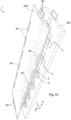
- each joint 6 (whether flexible or semi-rigid) between two supports 3 is coupled to an angle sensor (not illustrated on the figures 1a to 3a And 8a, 8b , and illustrated on the other hand on the figures 9a , 9b And 10 ) configured for measuring the angle of inclination between the two supports 3.
- the angle sensor is in the form of a flexible resistive sensor delivering measurement data reflecting a variation in resistance as a function of the bending of the flexible strip.
- a flexible resistive sensor or bending sensor, makes it possible to measure the angle of inclination between the two supports 3 (which corresponds to the angle of bending of the flexible strip) based on the exploitation of variations in resistance occurring when a conductive material is bent.
- the flexible resistive sensor thus behaves like a passive potentiometer whose resistance varies according to the deflection.
- the flexible resistive sensors 60 are integrated into the flexible membrane 300, for example being at least partially embedded in an elastomeric polymer layer.
- Such resistive sensors 60 can be arranged between the islands delimiting the elementary modules 2.
- the resistive sensors 60 can be offset to the sides of the flexible membrane 300, by arranging the resistive sensors 60 along the hinge axes AX, AY, so that the resistive sensors 60 can measure deflections at the level of the flexible bands along the corresponding hinge axes.
- the resistive sensors 60 which measure deflection along axes of articulation AY, parallel to the direction Y, are distributed alternately between the two longitudinal sides (sides in the direction X) of the flexible membrane 300. It is therefore to note that a resistive sensor 60 can be coupled to two or more joints.
- the flexible resistive sensors 60 are integrated into a flexible film 600 which is attached and fixed (in particular in a removable manner) on the flexible membrane 300, with the flexible resistive sensors which can either be superimposed with the flexible strips which, as a reminder, correspond to the parts of the flexible membrane located between the islands delimiting the elementary modules 2, or be offset on the sides of the flexible film 600 according to the same offset conformation as on the figures 9a And 9b .
- this flexible film 600 is necessarily transparent. On the other hand, if the flexible film 600 is positioned on the rear of the flexible membrane 300, then this flexible film 600 can be opaque or transparent.
- the flexible membrane 300 with its optoelectronic components 4, 5 can be for single use or not.
- the flexible film 600 with its flexible resistive sensors 60 can be single-use or reusable independently of the flexible membrane 300.
- the angle sensor is for example shaped to detect the adjustment notch occupied in the semi-rigid joint 6, this adjustment notch can then be associated with an angle of inclination.
- This angle sensor can for example include contactors coupled to each adjustment notch.
- joints 6 can possibly be the supports of the connection cables for the transmitters 4 and the receivers 5 and/or the seat of flexible electrical connections linking two elementary modules 2.
- the optoelectronic component(s) 4, 5 are all mounted on a front face of the support 3 concerned, this front face corresponding to the face which is applied to the part of the body to be analyzed.
- the support 3 thus has a frontal face, as well as a dorsal face opposite the frontal face, this dorsal face thus being opposite the part of the body to be analyzed.
- the optoelectronic component(s) 4, 5 are covered with a layer of transparent material.
- each elementary module 2 comprises, on its support 3, four transmitters 4 emitting at distinct lengths in the near infrared between 650 and 1000 nanometers, as well as four receivers 5.
- the four transmitters 4 are placed in the center of the support 3 and the four receivers 5 are placed on the periphery of the support 3, around the four receivers. In spatial subtraction calculations, and generally in the three-dimensional processing of data from receivers 5, the four transmitters 4 thus brought together could possibly be associated with a common spatial coordinate.
- Two receivers 5 are arranged on either side of the transmitters 4 in a longitudinal direction parallel to the longitudinal axis multiplying the receptors 5.
- two other receivers 5 are arranged on either side of the transmitters 4 in a transverse direction parallel to the transverse axis Y, so that these two other receivers 5 are offset axially in this transverse direction, also contributing to increasing transverse spectroscopic resolution by multiplying the receptors 5.
- each elementary module 2 comprises, on its support 3, four transmitters 4 emitting at distinct lengths in the near infrared between 650 and 1000 nanometers, as well as five receivers 5.
- a receiver 5, called the central receiver, is placed in the center of the support 3 and the four other receivers 5 are placed on the periphery of the support 3, around the central receiver 5.
- Two receivers 5 are arranged on either side of the central receiver 5 in a longitudinal direction parallel to the longitudinal axis longitudinal spectroscopic resolution by multiplying the receptors 5.
- two other receivers 5 are arranged on either side of the central receiver 5 in a transverse direction parallel to the transverse axis Y, so that these two other receivers 5 and the central receiver 5 are offset axially in this direction transverse, also contributing to increasing the transverse spectroscopic resolution by multiplying the receptors 5.
- the four transmitters 4 are placed at the four corners of the support 3 between the four receivers 5 arranged on the periphery.
- each elementary module 2 is identical to the elementary module 2 of the second embodiment, with the difference that some of the elementary modules 2 support another transmitter 4 (or possibly another receiver) which is carried by the support 3 via an arm 30 of so that said other transmitter 4 (or receiver) is arranged in an interstitial zone between four neighboring elementary modules 2.
- the emitters 4 can be commercially available, can be optical fibers coupled to an infrared source, laser diodes, light-emitting diodes or even optoelectronic components manufactured in a clean room.
- the emitters 4 can for example be made up of diodes of different sizes, combining large and small diodes.
- the receivers 5 can be CMOS sensors, photodiodes, photoresistors, phototransistors, photoelectric cells or even optoelectronic components manufactured in a clean room.
- elementary modules 2 comprising at least one transmitter 4, it is possible to have several transmitters 4 having different wavelengths. These emitters 4 are then advantageously grouped together, in particular in the center of the support 3, with a view to being considered during processing as a single light source. Thus, these transmitters 4 are behaves as a single light source with multiple wavelengths. The choice and number of wavelengths depends on the targeted applications, and in particular the targeted metabolites and molecules.
- the physiological sensor 1 Due to its ability to conform to the morphology of an organ or part of the body, the physiological sensor 1 allows in particular the monitoring of the perfusion of a wide range of organs or body parts.
- such a physiological sensor 1 can be considered, due to its conformability, to monitor tissue perfusion of various subcutaneous areas, starting with the frontal cortex, but also the kidneys, the mesentery and the muscles.
- This physiological sensor 1 can also be considered, due to its conformability and in sterile conditions, to monitor the perfusion of organs during a surgical procedure, such as the myocardial muscle during cardiac surgery.
- the joints 6 of this physiological sensor 1 make it possible to circumvent the morphological constraints of the application or measurement surface, including the creation of diffusing layers of air. These joints 6 also make it possible to reduce the length of the optical paths inside biological tissues, while gaining in measurement depth, by using the relief and sometimes roundness of their shape.
- the physiological sensor 1 can be configured and positioned in a semi-arc of a circle so that optoelectronic components 4, 5 can be aligned facing each other on either side of the organ or the body part.
- a physiological sensor 1 is used in association with a control unit (not illustrated) such as a computer terminal, a controller, a microcontroller, a processor, a microprocessor, a card electronics, data acquisition and processing card, or any other assembly of electronic components suitable for implementing the functionalities mentioned below.
- a control unit such as a computer terminal, a controller, a microcontroller, a processor, a microprocessor, a card electronics, data acquisition and processing card, or any other assembly of electronic components suitable for implementing the functionalities mentioned below.
- the control unit is thus connected, by wire or non-wire, to the transmitters 4, the receivers 5 and the joint angle sensors 6. Each transmitter 4 and each receiver 5 is addressed individually by the control unit.
- a sheet of cables connects the control unit to the transmitters 4, receivers 5 and the angle sensors, without hindering the mobility of the physiological sensor 1.
- the wiring is preferably located on the back of the elementary modules 2 (that is to say on the dorsal face of the support 3) so as not to reduce the useful surface of the physiological sensor 1 (that is to say the surface of the front faces of the supports 3).
- cables connect the transmitters 4, receivers 5 and angle sensors to a radiocommunication system carried by the physiological sensor 1, for example on the back of an elementary module 2 (in other words on a dorsal face of a support 3) or on a dedicated support 3 which does not necessarily carry a transmitter 4 and receiver 5.
- This radiocommunication system is in bidirectional radiocommunication with the control unit to send and receive data .
- the radiocommunication system can for example include a short-range radiocommunication chip (for example a maximum range of between one and five meters, or even around fifteen meters) using WBAN “Wireless Body Area Network” or WBASN “Wireless Body Area Sensor” technology.
- Network in order to be able to establish radio communication on a WBAN or WBASN network between the physiological sensor 1 and the control unit.
- WBAN or WBASN technology protocols the Zigbee TM and Bluetooth TM Low Energy (BLE) protocols can be retained.
- the control unit is configured to perform several functionalities including mainly the four functionalities described below, in other words to carry out several steps.
- the angle sensor of each joint 6 communicates, to the control unit, the value of the angle of inclination or the index of the adjustment notch or the value of the resistance of the passive potentiometer (depending on the technology used) which the control unit will translate into tilt angle.
- This first functionality can be repeated iteratively or regularly, in order to dynamically know these spatial coordinates.
- the part of the patient's body to be analyzed can change in its shape and size, such as for example inflating or deflating, and in this case the curved conformation of the physiological sensor 1 changes and therefore the spatial coordinates change.
- a command from the control unit updates the information relating to the inclination angles at each cycle (a cycle corresponding to the completion of the four functionalities or steps mentioned).
- the three-dimensional representation of the physiological sensor 1 is updated at each measurement cycle within the orthonormal reference frame (X, Y, Z) of the measurement volume.
- each transmitter 4 and each receiver 5 are located by their coordinates in the same orthonormal reference frame (X, Y, Z), in the same three-dimensional virtual space as that of the body or tissues analyzed.
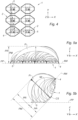
- the control unit thus makes it possible to construct a three-dimensional and virtual optoelectronic imprint of the physiological sensor 1 in situation on the organ or on the part of the body, and this three-dimensional optoelectronic imprint is placed in the orthonormal reference frame (X, Y, Z) , as visible on the figures 5a and 5b , to be used for the analysis of the signals measured by the receivers 5, and therefore for the graphic representation of the volumes analyzed under the physiological sensor 1, as explained later.
- the orthonormal reference frame X, Y, Z
- This area to be examined can be defined by its three-dimensional optoelectronic footprint at a wavelength of 800 nanometers for example, in order to represent the measurement volume.
- a second functionality is to activate the transmitters 4 individually and not concomitantly according to a predefined sequence.
- the control unit activates the transmitters 4 alternatively.
- the 4 transmitters can be synchronized with each other to chasing illumination, one after the other, without at any time two transmitters 4 being activated at the same time.
- a third functionality is a recovery and three-dimensional processing (for example according to a spatial subtraction method) of the measurements from the receivers 5 during the sequence as a function of the spatial coordinates of the transmitters 4 and the receivers 5.
- a fourth functionality is to construct a three-dimensional image representing a vascular or blood volume in an analysis volume, this vascular or blood volume being composed of voxels VO constructed from the three-dimensional processing, in particular according to a method of spatial subtraction of measurements from the receivers during the sequence.
- Data acquisition is based on spatial and temporal modulation of infrared emissions.
- the control unit is able to acquire images during the same period, thereby ensuring the temporal consistency of the acquisition.
- each elementary module 2 directly integrates a synchronization module between the transmitters 4 and the receivers 5.
- the absorption value measured at a receiver 5 which results from the activation of a transmitter 4 is unique information on the location of hemoglobins in the tissues crossed by the near infrared beam FI associated with the measurement torque 4, 5 concerned.
- FIG 4 illustrates several measuring couples 4, 5 by means of arrows which represent schematically of the near infrared beams of eight measuring pairs 4, 5 all associated with the same transmitter 4, including five measuring pairs 4, 5 along the transverse axis Y and three measuring pairs 4, 5 along the longitudinal axis X .
- the trajectory of the near-infrared beam for a measuring couple 4.5 is curvilinear or takes the form of an arc of diffuse light which passes through the organic tissues, as shown schematically on the figures 5a and 5b , and its relative depth PR with respect to the measurement axis AM corresponds to approximately one third of the spacing between the transmitter 4 and the receiver 5 of the measurement torque.
- each transmitter 4/receiver 5 spacing being known, likewise each spacing between the receivers 5 also being known, all combinations of measuring pairs 4, 5 having the same transmitter 4 are listed by the control unit.
- each transmitter 4 is associated with at least one pair of receivers 5, and preferably several pairs of receivers 5, for subtraction of the absorption measurements between the receivers 5 of the same pair; the pair or pairs of receivers 5 considered and associated with the transmitter 4 have the same measurement axis, in other words the transmitter 4 and the receivers 5 are aligned on the same measurement axis to carry out the spatial subtraction.
- the transmitters 4 and the pairs of receivers 5 attached to them are synchronized within the same illumination time. All of these successive illuminations occur at a speed suitable to consider that they take place in the same unit of time.
- the optoelectronic fingerprint constructed during the first step serves to establish the paired transmitters 4 and receivers 5 for spatial subtractions, these pairings being all singular and unique due to their measurement axes (singularity of the otic paths) as well as the spacings and the inclination angles to be considered between the optoelectronic components 4, 5 loaded from the physiological sensor 1.
- Each measurement pair 4, 5 represents a depth absorption value. It should be noted that the coordinates in X, Y and Z of the optoelectronic components 4, 5 are known from their arrangements on the physiological sensor 1 (arrangement of the elementary modules 2 within the physiological sensor 1 and arrangement of the optoelectronic components 4, 5 on their own elementary modules 2) and from the angles of inclination concerned.
- This depth absorption value is thus associated with a relative depth PR with respect to the measurement axis AM of the measurement pair 4, 5, and which corresponds to one third of the spacing between the transmitter 4 and the receiver 5 concerned.
- the relative depth PR corresponds to the measuring depth PM, in other words the height HA is zero.
- the spatial subtraction is carried out between all or part of the pairs of measurement pairs 4, 5 of the same transmitter 4 and receivers 5 aligned along the same measurement axis AM, by subtracting the shallowest signal (that corresponding to the measuring couple having the smallest spacing between the transmitter 4 and the receiver 5) to the deepest signal (that corresponding to the measuring pair having the greatest spacing between the transmitter 4 and the receiver 5) the receiver 6).
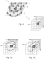
- the result of this subtraction between the absorption value of the shallowest signal and the absorption value of the deepest signal is associated with coordinates in X, Y, Z and is thus recorded in a volumetric map in the form of a voxel VO, as shown schematically on the Figure 6 , on the figure 7a where is illustrated a voxel VO resulting from imaging of a hematoma type blood volume, or on the figure 7b where is illustrated a voxel VO resulting from imaging of a blood vessel type blood volume.
- the coordinates of the voxel depend on the coordinates of the transmitter 4 and the two receivers 5 considered, and therefore depend, among other things, on the inclination angle(s) concerned.
- the physiological sensor 1 is flat between the transmitter 4 and the receivers 5 considered, the measurement axis which passes through the transmitter 4 and the aligned receivers 5 will form the reference axis. If the physiological sensor 1 presents a curvature between the transmitter 4 and the receiver 5 of the measuring pair 4, 5 considered, the bisector of the angle formed by the axes passing through the transmitter 4 and the two receivers 5 will form the reference axis.
- reconstruction algorithms in particular based on photon detection thresholds, can be used to reconstruct a three-dimensional map as well as a volumetry of homogeneous absorption zones.
- the voxels can be crossed between them, to refine the resolution.
- a variant of the spatial subtraction method could be a tomography method by establishing a contrast map, or even a point cloud reconstruction method consisting of considering all the absorption values by each receptor 5 at each length d wave to form a cloud of points. Reconstruction algorithms will then focus on identifying its coherence in relation to the different volumes of homogeneous absorption, in order to enable a three-dimensional graphic representation.
- the physiological sensor 1 is favored for medical applications concerning the hemodynamics of patients, by using wavelengths affine with hemoglobins such as 803 nanometers, example of an isobestic point absorption of hemoglobins, or the wavelengths more closely related to oxygenated and deoxygenated hemoglobins.
- a wavelength close to the isosbestic point of hemoglobins at 803 nanometers can thus be used to establish a high contrast three-dimensional map.
- the hemoglobins only circulate in the vascular network, and the organs, bones and integuments are of variable vascularization, a discrimination of biological tissues can thus be made.
- the physiological sensor 1 makes it possible to discriminate the scalp, the skull, the white matter from the gray matter, each of different vascular density.
- wavelengths in the near infrared on either side of 800 nanometers can be used for the discrimination of oxygenated hemoglobins from deoxygenated hemoglobins.
- the optical paths of the light beams of these different wavelengths can then either be considered as similar to those of the wavelength at 800 nanometers, due to their juxtaposition to this on the elementary modules 2 concerned, or be considered in relation to these during processing by the reconstruction algorithms.
- the process of three-dimensional representation of elementary modules 2 and three-dimensional processing (eg. according to a spatial subtraction method, a tomography method, or according to a point cloud reconstruction method) is applied identically to the process with the four steps previously described.
- a first application is the local or regional dosage, dynamic, in trend or in absolute value, of the tissue in targeted molecule.
- the purpose of this dosage is to know the concentration, that is to say the ratio between the quantity of the targeted molecule and the measurement volume.
- the three-dimensional maps obtained at different wavelengths reflecting variable tissue absorption levels are combined and superimposed to be able to extract the dosage.
- the optical paths are reproduced at at least one other length of specific waves affine with deoxyhemoglobin (Hb), for example between 650 and 800 nanometers.
- Hb deoxyhemoglobin
- At least one second three-dimensional map obtained with this other different wavelength will allow, by combination with the first three-dimensional map obtained with the wavelength close to 800 nanometers, to represent the oxygenation levels of the various tissue strata identified.
- the precision of discrimination of the molecules sought can be increased by increasing the number of wavelengths used.
- the quantification of their absorption relative to a target measurement volume allows their local dosage and the calculation of a relative or absolute value of tissue oxygen saturation (STO2).
- a target measurement volume for example volume of frontal and temporal cortex
- STO2 tissue oxygen saturation
- the regional quantity of hemoglobin can be calculated, as well as its concentration.
- the optical paths are reproduced at wavelengths specific to the targeted metabolite, making it possible to discriminate it, and thus to obtain an in vivo dosage of this metabolite, regionally, on a scale of the organ.
- a second application is the determination of cerebral vascular volume and the autoregulatory plateau. Since hemoglobins only circulate in the vascular network, at constant hematocrit, the invention allows continuous measurement of absorption variations at 800 nm, and therefore measurement of dynamic variations of the vascular network (vasodilation and vasoconstriction) under the physiological sensor 1 which follows the roundness of the surface of the frontal hemispheres. Thus, with the physiological sensor 1, it is possible to obtain a punctual, or even continuous, and non-invasive measurement of the cerebral vascular volume after calibration of the hematocrit. This physiological data can be combined with others to determine the cerebral autoregulation threshold of patients.
- a third application is the measurement of vasodilation reserve and endothelial properties.
- a fourth application is the evaluation of tissue perfusion in the case of obliterating arteriopathy of the lower limbs.
Landscapes
- Health & Medical Sciences (AREA)
- Life Sciences & Earth Sciences (AREA)
- Physics & Mathematics (AREA)
- Heart & Thoracic Surgery (AREA)
- Molecular Biology (AREA)
- Cardiology (AREA)
- Biophysics (AREA)
- Pathology (AREA)
- Engineering & Computer Science (AREA)
- Biomedical Technology (AREA)
- Veterinary Medicine (AREA)
- Medical Informatics (AREA)
- Public Health (AREA)
- Surgery (AREA)
- Animal Behavior & Ethology (AREA)
- General Health & Medical Sciences (AREA)
- Physiology (AREA)
- Hematology (AREA)
- Spectroscopy & Molecular Physics (AREA)
- Measurement Of The Respiration, Hearing Ability, Form, And Blood Characteristics Of Living Organisms (AREA)
- Investigating Or Analysing Materials By Optical Means (AREA)
Claims (14)
- Nahinfrarot-Spektroskopiesystem, das einen physiologischen Sensor (1) für eine Nahinfrarot-Spektroskopie in verschiedenen Tiefen umfasst, wobei der physiologische Sensor (1) optoelektronische Komponenten (4, 5) umfasst, die Strahlensender (4) im nahen Infrarotbereich und lichtempfindliche Empfänger (5) im nahen Infrarotbereich umfassen, wobei der physiologische Sensor (1) Elementarmodule (2) umfasst, die jeweils mit mindestens einer optoelektronischen Komponente (4, 5) versehen sind, wobei jedes Elementarmodul (2) mit mindestens einem benachbarten Elementarmodul (2) mittels eines Gelenks (6) verbunden ist, das für eine Relativbewegung zwischen den Elementarmodulen (2) entsprechend mehreren Neigungswinkeln konfiguriert ist, wobei die Elementarmodule (2) mindestens mittels der Gelenke (6) zusammengefügt sind und eine optoelektronische Ausbreitung bilden, die zwischen Folgendem konfigurierbar ist:- einer planaren Konfiguration gemäß einer Hauptebene (PP), in der jedes Gelenk (6) einen Neigungswinkel von Null in Bezug auf die Hauptebene (PP) aufweist, und- eine Reihe gekrümmter Gestaltungen, bei denen mindestens eines der Gelenke (6) einen Neigungswinkel ungleich Null in Bezug auf die Hauptebene (PP) aufweist;wobei das Nahinfrarot-Spektroskopiesystem ferner eine Steuereinheit umfasst, die mit den Sendern (4) und Empfängern (5) des physiologischen Sensors (1) verbunden sind;wobei das Nahinfrarot-Spektroskopiesystem dadurch gekennzeichnet ist, dass jedes Gelenk (6) zwischen zwei Elementarmodulen (2) mit einem Winkelsensor gekoppelt ist, der für eine Messung des Neigungswinkels zwischen den beiden Elementarmodulen (2) konfiguriert ist;und dadurch, dass die Steuereinheit mit jedem Winkelsensor (60) verbunden und dazu konfiguriert ist, die räumlichen Koordinaten jedes Senders (4) und jedes Empfängers (5) basierend auf den von den Winkelsensoren (60) ausgegebenen Messdaten und den Positionierungen und den relativen Abständen zwischen den Sendern (4) und den Empfängern (5) festzulegen, wobei die Steuereinheit einerseits mit den Sendern (4) des physiologischen Sensors (1), um die Sender (4) einzeln und nicht gleichzeitig gemäß einer vordefinierten Reihenfolge zu aktivieren, und andererseits mit den Empfängern (5) des physiologischen Sensors (1) für ein Abrufen und ein dreidimensionales Verarbeiten der von den Empfängern (5) während der Reihenfolge ausgegebenen Messungen basierend auf den räumlichen Koordinaten der Sender (4) und der Empfänger (5) verbunden ist.
- Nahinfrarot-Spektroskopiesystem nach Anspruch 1, wobei mindestens ein oder jedes Gelenk zwischen zwei Elementarmodulen (2) ein flexibles Gelenk ist, das einen flexiblen Streifen umfasst, der für eine Relativbewegung zwischen den Elementarmodulen (2) durch Biegen des flexiblen Streifens konfiguriert ist.
- Nahinfrarot-Spektroskopiesystem nach Anspruch 2, wobei jedes Elementarmodul (2) einen starren oder flexiblen Träger (3) umfasst, auf dem mindestens eine optoelektronische Komponente (4, 5) angeordnet ist, und der flexible Streifen des flexiblen Gelenks (6) zwischen zwei Elementarmodulen (2) zwischen den Trägern (3) der beiden Elementarmodule (2) verbunden ist.
- Nahinfrarot-Spektroskopiesystem nach Anspruch 3, umfassend eine flexible Membran (300), auf der die optoelektronischen Komponenten (4, 5) angeordnet und in die Elementarmodule (2) begrenzenden Inseln verteilt sind, wobei der flexible Streifen des flexiblen Gelenks (6) zwischen zwei Elementarmodulen (2) durch einen Abschnitt der flexiblen Membran (300) gebildet wird, der sich zwischen den die beiden Elementarmodule (2) begrenzenden Inseln erstreckt.
- Nahinfrarot-Spektroskopiesystem nach Anspruch 4, wobei die flexible Membran (300) mindestens eine elastomere Polymerschicht umfasst, in der die optoelektronischen Komponenten (4, 5) mindestens teilweise eingebettet sind.
- Nahinfrarot-Spektroskopiesystem nach einem der Ansprüche 2 bis 5, wobei für ein flexibles Gelenk, das den flexiblen Streifen umfasst, das flexible Gelenk mit einem Winkelsensor gekoppelt ist, der einen flexiblen Widerstandssensor (60) umfasst, der einen Messwert liefert, der eine Widerstandsänderung basierend auf der Biegung des flexiblen Streifens widerspiegelt.
- Nahinfrarot-Spektroskopiesystem nach Anspruch 6, wobei der flexible Widerstandssensor (60) in den flexiblen Streifen integriert oder in Bezug auf den flexiblen Streifen versetzt ist, indem er in eine am flexiblen Streifen befestigte flexible Lamelle, insbesondere lösbar, integriert ist, so dass eine Durchbiegung des flexiblen Streifens zu einer Durchbiegung der flexiblen Lamelle führt.
- Nahinfrarot-Spektroskopiesystem nach einem der vorhergehenden Ansprüche, wobei jedes Elementarmodul (2) einen starren oder flexiblen Träger (3) umfasst, auf dem mindestens eine optoelektronische Komponente (4; 5) angeordnet ist, und jeder Träger (3) zwei gegenüberliegende und parallele Längskanten (31) und zwei gegenüberliegende und parallele Querkanten (32) umfasst, und jedes Gelenk (6) entweder zwei Querkanten (32), die an zwei benachbarte jeweilige Träger (3) angrenzen, oder zwei Längskanten (31) verbindet, die an zwei benachbarte jeweilige Träger (3) angrenzen.
- Nahinfrarot-Spektroskopiesystem nach einem der vorhergehenden Ansprüche, wobei in der planaren Konfiguration der optoelektronischen Ausbreitung jedes Gelenk (6) zwischen zwei Elementarmodulen (2) ein Gelenk (6) ist, das um eine Gelenkachse schwenkt, die sich in der Hauptebene (PP) erstreckt.
- Spektroskopiesystem nach einem der vorhergehenden Ansprüche, wobei die Steuereinheit für eine dreidimensionale Verarbeitung der von den Empfängern (5) während der Reihenfolge ausgegebenen Messungen gemäß einem räumlichen Subtraktionsverfahren oder gemäß einem Tomographieverfahren mit Kontrastkartenerstellung oder gemäß einem Punktwolken-Rekonstruktionsverfahren konfiguriert ist.
- Spektroskopiesystem nach dem vorhergehenden Anspruch, wobei die Steuereinheit für eine dreidimensionale Verarbeitung bei jeder Aktivierung eines Senders (4) nur von Messungen, die von Empfängern (5) ausgegeben werden, die basierend auf einer relativen Position in Bezug auf den festgelegten aktivierten Sender (4) aus ihren räumlichen Koordinaten ausgewählt wurden, konfiguriert ist.
- Nahinfrarot-Spektroskopieverfahren, das durch ein Spektroskopiesystem nach einem der vorhergehenden Ansprüche durchgeführt wird, wobei das Spektroskopieverfahren die folgenden Schritte umfasst:- Sammeln von Messdaten, die von den mit jedem Gelenk (6) gekoppelten Winkelsensoren (60) ausgegeben werden;- Festlegen der räumlichen Koordinaten jedes Senders (4) und jedes Empfänger (5) basierend auf den Messdaten, die von den Winkelsensoren (60) ausgegeben werden;- einzelnes und nicht gleichzeitiges Aktivieren der Sender (4) gemäß einer vordefinierten Reihenfolge;- Abrufen und dreidimensionales Verarbeiten der Messungen, die während der Reihenfolge von den Empfängern (5) basierend auf den räumlichen Koordinaten der Sender (4) und der Empfänger (5) ausgegeben werden.
- Spektroskopieverfahren nach Anspruch 12, wobei das dreidimensionale Verarbeiten der von den Empfängern (5) während der Reihenfolge ausgegebenen Messungen gemäß einem räumlichen Subtraktionsverfahren oder gemäß einem Tomographieverfahren mit Kontrastkartenerstellung oder gemäß einem Punktwolken-Rekonstruktionsverfahren durchgeführt wird.
- Spektroskopieverfahren nach einem der Ansprüche 12 und 13, wobei auf den Schritt des Abrufens und Verarbeitens ein Schritt des Erstellens eines dreidimensionalen Bilds folgt, das ein Gefäß- oder Blutvolumen in einem Analysevolumen darstellt, wobei das Gefäß- oder Blutvolumen aus Voxeln besteht, die von der dreidimensionalen Verarbeiten der von den Empfänger (5) während der Reihenfolge ausgegebenen Messungen erstellt wurden.
Applications Claiming Priority (3)
| Application Number | Priority Date | Filing Date | Title |
|---|---|---|---|
| FR1750207A FR3061646B1 (fr) | 2017-01-10 | 2017-01-10 | Capteur physiologique pour une spectroscopie en proche infrarouge a differentes profondeurs |
| FR1753888A FR3065869B1 (fr) | 2017-05-03 | 2017-05-03 | Capteur physiologique pour une spectroscopie en proche infrarouge a differentes profondeurs |
| PCT/FR2018/050046 WO2018162808A1 (fr) | 2017-01-10 | 2018-01-09 | Capteur physiologique pour une spectroscopie en proche infrarouge à différentes profondeurs |
Publications (3)
| Publication Number | Publication Date |
|---|---|
| EP3568065A1 EP3568065A1 (de) | 2019-11-20 |
| EP3568065C0 EP3568065C0 (de) | 2024-03-13 |
| EP3568065B1 true EP3568065B1 (de) | 2024-03-13 |
Family
ID=61148254
Family Applications (1)
| Application Number | Title | Priority Date | Filing Date |
|---|---|---|---|
| EP18702747.9A Active EP3568065B1 (de) | 2017-01-10 | 2018-01-09 | Physiologischer sensor für nahinfrarot-spektroskopie an verschiedenen tiefen |
Country Status (3)
| Country | Link |
|---|---|
| US (1) | US11311194B2 (de) |
| EP (1) | EP3568065B1 (de) |
| WO (1) | WO2018162808A1 (de) |
Families Citing this family (35)
| Publication number | Priority date | Publication date | Assignee | Title |
|---|---|---|---|---|
| EP4434457A3 (de) | 2014-01-07 | 2024-12-18 | Opsolution GmbH | Vorrichtung und verfahren zur bestimmung einer konzentration in einer probe |
| US10340408B1 (en) | 2018-05-17 | 2019-07-02 | Hi Llc | Non-invasive wearable brain interface systems including a headgear and a plurality of self-contained photodetector units configured to removably attach to the headgear |
| US10420498B1 (en) | 2018-06-20 | 2019-09-24 | Hi Llc | Spatial and temporal-based diffusive correlation spectroscopy systems and methods |
| US11213206B2 (en) | 2018-07-17 | 2022-01-04 | Hi Llc | Non-invasive measurement systems with single-photon counting camera |
| AU2020268718B2 (en) | 2019-05-06 | 2025-04-03 | Hi Llc | Photodetector architectures for time-correlated single photon counting |
| CA3137921A1 (en) | 2019-06-06 | 2020-12-10 | Hi Llc | Photodetector systems with low-power time-to-digital converter architectures |
| WO2021167890A1 (en) * | 2020-02-21 | 2021-08-26 | Hi Llc | Wearable module assemblies for an optical measurement system |
| US11630310B2 (en) | 2020-02-21 | 2023-04-18 | Hi Llc | Wearable devices and wearable assemblies with adjustable positioning for use in an optical measurement system |
| WO2021167876A1 (en) | 2020-02-21 | 2021-08-26 | Hi Llc | Methods and systems for initiating and conducting a customized computer-enabled brain research study |
| US11969259B2 (en) | 2020-02-21 | 2024-04-30 | Hi Llc | Detector assemblies for a wearable module of an optical measurement system and including spring-loaded light-receiving members |
| US11950879B2 (en) | 2020-02-21 | 2024-04-09 | Hi Llc | Estimation of source-detector separation in an optical measurement system |
| US11883181B2 (en) | 2020-02-21 | 2024-01-30 | Hi Llc | Multimodal wearable measurement systems and methods |
| US11771362B2 (en) | 2020-02-21 | 2023-10-03 | Hi Llc | Integrated detector assemblies for a wearable module of an optical measurement system |
| US12029558B2 (en) | 2020-02-21 | 2024-07-09 | Hi Llc | Time domain-based optical measurement systems and methods configured to measure absolute properties of tissue |
| US12144653B2 (en) | 2020-02-21 | 2024-11-19 | Hi Llc | Systems, circuits, and methods for reducing common-mode noise in biopotential recordings |
| US11864867B2 (en) | 2020-03-20 | 2024-01-09 | Hi Llc | Control circuit for a light source in an optical measurement system by applying voltage with a first polarity to start an emission of a light pulse and applying voltage with a second polarity to stop the emission of the light pulse |
| US11245404B2 (en) | 2020-03-20 | 2022-02-08 | Hi Llc | Phase lock loop circuit based signal generation in an optical measurement system |
| US11819311B2 (en) | 2020-03-20 | 2023-11-21 | Hi Llc | Maintaining consistent photodetector sensitivity in an optical measurement system |
| US11857348B2 (en) | 2020-03-20 | 2024-01-02 | Hi Llc | Techniques for determining a timing uncertainty of a component of an optical measurement system |
| US12138068B2 (en) | 2020-03-20 | 2024-11-12 | Hi Llc | Techniques for characterizing a nonlinearity of a time-to-digital converter in an optical measurement system |
| US11187575B2 (en) | 2020-03-20 | 2021-11-30 | Hi Llc | High density optical measurement systems with minimal number of light sources |
| US11877825B2 (en) | 2020-03-20 | 2024-01-23 | Hi Llc | Device enumeration in an optical measurement system |
| US11645483B2 (en) | 2020-03-20 | 2023-05-09 | Hi Llc | Phase lock loop circuit based adjustment of a measurement time window in an optical measurement system |
| WO2021188488A1 (en) | 2020-03-20 | 2021-09-23 | Hi Llc | Bias voltage generation in an optical measurement system |
| WO2021188487A1 (en) | 2020-03-20 | 2021-09-23 | Hi Llc | Temporal resolution control for temporal point spread function generation in an optical measurement system |
| WO2021188490A1 (en) * | 2020-03-20 | 2021-09-23 | Hi Llc | Dynamic range optimization in an optical measurement system |
| US12059262B2 (en) | 2020-03-20 | 2024-08-13 | Hi Llc | Maintaining consistent photodetector sensitivity in an optical measurement system |
| US11903676B2 (en) | 2020-03-20 | 2024-02-20 | Hi Llc | Photodetector calibration of an optical measurement system |
| US12059270B2 (en) | 2020-04-24 | 2024-08-13 | Hi Llc | Systems and methods for noise removal in an optical measurement system |
| US11045131B1 (en) * | 2020-06-03 | 2021-06-29 | Brain Electrophysiology Laboratory Company, LLC | Truncated icosahedral neural sensor net and modular elements therefor |
| KR20220010890A (ko) * | 2020-07-20 | 2022-01-27 | 삼성전자주식회사 | 생체 이미징 시스템 및 생체 이미징 방법 |
| US12436280B2 (en) | 2020-08-11 | 2025-10-07 | Hi Llc | Maintaining consistent photodetector sensitivity in an optical measurement system |
| CN112401881B (zh) * | 2020-10-27 | 2021-08-10 | 北京航空航天大学 | 一种穿戴式fNIRS脑成像系统 |
| KR20220125547A (ko) * | 2021-03-05 | 2022-09-14 | 삼성전자주식회사 | 생체 이미징 시스템 및 생체 이미징 방법 |
| FR3135164B1 (fr) | 2022-05-02 | 2024-03-22 | Braindex S A S | Système de pose par superposition haute précision d’une membrane adhésive sur un dispositif optoélectronique |
Family Cites Families (11)
| Publication number | Priority date | Publication date | Assignee | Title |
|---|---|---|---|---|
| JP4090699B2 (ja) * | 2001-04-02 | 2008-05-28 | 株式会社日立製作所 | 生体光計測装置 |
| JP5481032B2 (ja) * | 2008-02-20 | 2014-04-23 | 株式会社日立製作所 | 生体光計測用プローブ及びそれを用いた生体光計測装置 |
| US8444564B2 (en) * | 2009-02-02 | 2013-05-21 | Jointvue, Llc | Noninvasive diagnostic system |
| US8188433B2 (en) | 2009-05-26 | 2012-05-29 | Nellcor Puritan Bennett Llc | Physiological sensor having reduced sensitivity to interference |
| ES2900518T3 (es) | 2009-12-15 | 2022-03-17 | The Government Of The U S A As Represented By The Secretary Dept Of Health And Human Services | Dispositivo portátil de detección y discriminación, y sistemas y aparatos relacionados para detectar hematomas |
| US9545223B2 (en) * | 2011-03-02 | 2017-01-17 | Board Of Regents, The University Of Texas System | Functional near infrared spectroscopy imaging system and method |
| US20140275891A1 (en) | 2013-03-13 | 2014-09-18 | Cephalogics, LLC | Optical tomography sensor and related apparatus and methods |
| WO2014165049A1 (en) | 2013-03-13 | 2014-10-09 | The Regents Of The University Of California | Multi-modal depth-resolved tissue status monitor |
| US20140371566A1 (en) * | 2013-06-14 | 2014-12-18 | Cardiothrive, Inc. | Conforming patient contact interface and method for using same |
| WO2015070162A2 (en) | 2013-11-08 | 2015-05-14 | University Of Houston System | Imaging system for intra-operative and post-operative blood perfusion monitoring |
| US10912504B2 (en) | 2014-01-14 | 2021-02-09 | Canon U.S.A., Inc. | Near-infrared spectroscopy and diffuse correlation spectroscopy device and methods |
-
2018
- 2018-01-09 EP EP18702747.9A patent/EP3568065B1/de active Active
- 2018-01-09 WO PCT/FR2018/050046 patent/WO2018162808A1/fr not_active Ceased
-
2019
- 2019-07-10 US US16/507,545 patent/US11311194B2/en active Active
Also Published As
| Publication number | Publication date |
|---|---|
| EP3568065C0 (de) | 2024-03-13 |
| US20190343395A1 (en) | 2019-11-14 |
| US11311194B2 (en) | 2022-04-26 |
| WO2018162808A1 (fr) | 2018-09-13 |
| EP3568065A1 (de) | 2019-11-20 |
Similar Documents
| Publication | Publication Date | Title |
|---|---|---|
| WO2018162808A1 (fr) | Capteur physiologique pour une spectroscopie en proche infrarouge à différentes profondeurs | |
| US11033207B2 (en) | Dynamic optical tomographic imaging devices methods and systems | |
| US20220054017A1 (en) | Laser Optoacoustic Ultrasonic Imaging System (LOUIS) and Methods of Use | |
| JP6548639B2 (ja) | 光生理センサ及び組み立て方法 | |
| CN103735274B (zh) | 一种局部脑组织血氧血容绝对量检测装置及检测方法 | |
| US20190239751A1 (en) | Compact Optical Imaging Devices, Systems, and Methods | |
| US20100016732A1 (en) | Apparatus and method for neural-signal capture to drive neuroprostheses or control bodily function | |
| US20150041656A1 (en) | Multiplexed noninvasive analyzer apparatus and method of use thereof | |
| CN115211830B (zh) | 近红外扩散相干光谱局部脑血流散斑成像装置及检测方法 | |
| CA2731064A1 (en) | Method and apparatus for neural-signal capture to drive neuroprostheses or control bodily function | |
| US12533031B2 (en) | Flexible optical imaging bands and optical imaging methods for the diagnosis and monitoring of systemic lupus erythematosus in finger joints | |
| FR3065869B1 (fr) | Capteur physiologique pour une spectroscopie en proche infrarouge a differentes profondeurs | |
| Liu et al. | Reconstructions for continuous-wave diffuse optical tomography by a globally convergent method | |
| FR3061646A1 (fr) | Capteur physiologique pour une spectroscopie en proche infrarouge a differentes profondeurs | |
| US20250089818A1 (en) | Smart Bra with Optical Sensors for Breast Cancer Screening | |
| US20240298968A1 (en) | Smart Bra with Light Transmission for Optical Detection of Abnormal Breast Tissue | |
| US20230389803A1 (en) | Multilayer Smart Bra or Bra Insert for Optical Detection of Breast Cancer | |
| Joshi et al. | Smart Glucometer for Personalized Health Management of Diabetes Care | |
| US12551125B2 (en) | Handheld non-invasive compartment syndrome detector | |
| CN120381268A (zh) | 一种基于复合单像素散射补偿的深层近红外结构成像方法及系统 | |
| Lam | High-Speed, Multi-Modal Diffuse Optical Spectroscopic Imaging for Translational Biophotonics | |
| Larin | Measurement of tissue optical properties with optical coherence tomography: implication for noninvasive blood glucose concentration monitoring | |
| Zheng | Opto-physiological modelling of imaging photoplethysmography | |
| Lasker et al. | Dynamic optical tomographic imager with optimized digital lock-in filtering | |
| Lee et al. | Conference 9319: Optical Tomography and Spectroscopy of Tissue XI |
Legal Events
| Date | Code | Title | Description |
|---|---|---|---|
| STAA | Information on the status of an ep patent application or granted ep patent |
Free format text: STATUS: UNKNOWN |
|
| STAA | Information on the status of an ep patent application or granted ep patent |
Free format text: STATUS: THE INTERNATIONAL PUBLICATION HAS BEEN MADE |
|
| PUAI | Public reference made under article 153(3) epc to a published international application that has entered the european phase |
Free format text: ORIGINAL CODE: 0009012 |
|
| STAA | Information on the status of an ep patent application or granted ep patent |
Free format text: STATUS: REQUEST FOR EXAMINATION WAS MADE |
|
| 17P | Request for examination filed |
Effective date: 20190808 |
|
| AK | Designated contracting states |
Kind code of ref document: A1 Designated state(s): AL AT BE BG CH CY CZ DE DK EE ES FI FR GB GR HR HU IE IS IT LI LT LU LV MC MK MT NL NO PL PT RO RS SE SI SK SM TR |
|
| AX | Request for extension of the european patent |
Extension state: BA ME |
|
| RIN1 | Information on inventor provided before grant (corrected) |
Inventor name: CUSSAC, THIERRY Inventor name: LUNA ARRIAGA, ANTONIO |
|
| DAV | Request for validation of the european patent (deleted) | ||
| DAX | Request for extension of the european patent (deleted) | ||
| STAA | Information on the status of an ep patent application or granted ep patent |
Free format text: STATUS: EXAMINATION IS IN PROGRESS |
|
| 17Q | First examination report despatched |
Effective date: 20200729 |
|
| GRAP | Despatch of communication of intention to grant a patent |
Free format text: ORIGINAL CODE: EPIDOSNIGR1 |
|
| STAA | Information on the status of an ep patent application or granted ep patent |
Free format text: STATUS: GRANT OF PATENT IS INTENDED |
|
| INTG | Intention to grant announced |
Effective date: 20231011 |
|
| GRAS | Grant fee paid |
Free format text: ORIGINAL CODE: EPIDOSNIGR3 |
|
| GRAA | (expected) grant |
Free format text: ORIGINAL CODE: 0009210 |
|
| STAA | Information on the status of an ep patent application or granted ep patent |
Free format text: STATUS: THE PATENT HAS BEEN GRANTED |
|
| AK | Designated contracting states |
Kind code of ref document: B1 Designated state(s): AL AT BE BG CH CY CZ DE DK EE ES FI FR GB GR HR HU IE IS IT LI LT LU LV MC MK MT NL NO PL PT RO RS SE SI SK SM TR |
|
| REG | Reference to a national code |
Ref country code: GB Ref legal event code: FG4D Free format text: NOT ENGLISH |
|
| REG | Reference to a national code |
Ref country code: CH Ref legal event code: EP |
|
| REG | Reference to a national code |
Ref country code: DE Ref legal event code: R096 Ref document number: 602018066527 Country of ref document: DE |
|
| REG | Reference to a national code |
Ref country code: IE Ref legal event code: FG4D Free format text: LANGUAGE OF EP DOCUMENT: FRENCH |
|
| U01 | Request for unitary effect filed |
Effective date: 20240409 |
|
| U07 | Unitary effect registered |
Designated state(s): AT BE BG DE DK EE FI FR IT LT LU LV MT NL PT SE SI Effective date: 20240416 |
|
| PG25 | Lapsed in a contracting state [announced via postgrant information from national office to epo] |
Ref country code: GR Free format text: LAPSE BECAUSE OF FAILURE TO SUBMIT A TRANSLATION OF THE DESCRIPTION OR TO PAY THE FEE WITHIN THE PRESCRIBED TIME-LIMIT Effective date: 20240614 |
|
| PG25 | Lapsed in a contracting state [announced via postgrant information from national office to epo] |
Ref country code: RS Free format text: LAPSE BECAUSE OF FAILURE TO SUBMIT A TRANSLATION OF THE DESCRIPTION OR TO PAY THE FEE WITHIN THE PRESCRIBED TIME-LIMIT Effective date: 20240613 Ref country code: HR Free format text: LAPSE BECAUSE OF FAILURE TO SUBMIT A TRANSLATION OF THE DESCRIPTION OR TO PAY THE FEE WITHIN THE PRESCRIBED TIME-LIMIT Effective date: 20240313 |
|
| PG25 | Lapsed in a contracting state [announced via postgrant information from national office to epo] |
Ref country code: ES Free format text: LAPSE BECAUSE OF FAILURE TO SUBMIT A TRANSLATION OF THE DESCRIPTION OR TO PAY THE FEE WITHIN THE PRESCRIBED TIME-LIMIT Effective date: 20240313 |
|
| PG25 | Lapsed in a contracting state [announced via postgrant information from national office to epo] |
Ref country code: RS Free format text: LAPSE BECAUSE OF FAILURE TO SUBMIT A TRANSLATION OF THE DESCRIPTION OR TO PAY THE FEE WITHIN THE PRESCRIBED TIME-LIMIT Effective date: 20240613 Ref country code: NO Free format text: LAPSE BECAUSE OF FAILURE TO SUBMIT A TRANSLATION OF THE DESCRIPTION OR TO PAY THE FEE WITHIN THE PRESCRIBED TIME-LIMIT Effective date: 20240613 Ref country code: HR Free format text: LAPSE BECAUSE OF FAILURE TO SUBMIT A TRANSLATION OF THE DESCRIPTION OR TO PAY THE FEE WITHIN THE PRESCRIBED TIME-LIMIT Effective date: 20240313 Ref country code: GR Free format text: LAPSE BECAUSE OF FAILURE TO SUBMIT A TRANSLATION OF THE DESCRIPTION OR TO PAY THE FEE WITHIN THE PRESCRIBED TIME-LIMIT Effective date: 20240614 Ref country code: ES Free format text: LAPSE BECAUSE OF FAILURE TO SUBMIT A TRANSLATION OF THE DESCRIPTION OR TO PAY THE FEE WITHIN THE PRESCRIBED TIME-LIMIT Effective date: 20240313 |
|
| PG25 | Lapsed in a contracting state [announced via postgrant information from national office to epo] |
Ref country code: IS Free format text: LAPSE BECAUSE OF FAILURE TO SUBMIT A TRANSLATION OF THE DESCRIPTION OR TO PAY THE FEE WITHIN THE PRESCRIBED TIME-LIMIT Effective date: 20240713 |
|
| PG25 | Lapsed in a contracting state [announced via postgrant information from national office to epo] |
Ref country code: SM Free format text: LAPSE BECAUSE OF FAILURE TO SUBMIT A TRANSLATION OF THE DESCRIPTION OR TO PAY THE FEE WITHIN THE PRESCRIBED TIME-LIMIT Effective date: 20240313 |
|
| PG25 | Lapsed in a contracting state [announced via postgrant information from national office to epo] |
Ref country code: CZ Free format text: LAPSE BECAUSE OF FAILURE TO SUBMIT A TRANSLATION OF THE DESCRIPTION OR TO PAY THE FEE WITHIN THE PRESCRIBED TIME-LIMIT Effective date: 20240313 |
|
| PG25 | Lapsed in a contracting state [announced via postgrant information from national office to epo] |
Ref country code: PL Free format text: LAPSE BECAUSE OF FAILURE TO SUBMIT A TRANSLATION OF THE DESCRIPTION OR TO PAY THE FEE WITHIN THE PRESCRIBED TIME-LIMIT Effective date: 20240313 |
|
| PG25 | Lapsed in a contracting state [announced via postgrant information from national office to epo] |
Ref country code: SK Free format text: LAPSE BECAUSE OF FAILURE TO SUBMIT A TRANSLATION OF THE DESCRIPTION OR TO PAY THE FEE WITHIN THE PRESCRIBED TIME-LIMIT Effective date: 20240313 |
|
| PG25 | Lapsed in a contracting state [announced via postgrant information from national office to epo] |
Ref country code: SM Free format text: LAPSE BECAUSE OF FAILURE TO SUBMIT A TRANSLATION OF THE DESCRIPTION OR TO PAY THE FEE WITHIN THE PRESCRIBED TIME-LIMIT Effective date: 20240313 Ref country code: SK Free format text: LAPSE BECAUSE OF FAILURE TO SUBMIT A TRANSLATION OF THE DESCRIPTION OR TO PAY THE FEE WITHIN THE PRESCRIBED TIME-LIMIT Effective date: 20240313 Ref country code: RO Free format text: LAPSE BECAUSE OF FAILURE TO SUBMIT A TRANSLATION OF THE DESCRIPTION OR TO PAY THE FEE WITHIN THE PRESCRIBED TIME-LIMIT Effective date: 20240313 Ref country code: PL Free format text: LAPSE BECAUSE OF FAILURE TO SUBMIT A TRANSLATION OF THE DESCRIPTION OR TO PAY THE FEE WITHIN THE PRESCRIBED TIME-LIMIT Effective date: 20240313 Ref country code: IS Free format text: LAPSE BECAUSE OF FAILURE TO SUBMIT A TRANSLATION OF THE DESCRIPTION OR TO PAY THE FEE WITHIN THE PRESCRIBED TIME-LIMIT Effective date: 20240713 Ref country code: CZ Free format text: LAPSE BECAUSE OF FAILURE TO SUBMIT A TRANSLATION OF THE DESCRIPTION OR TO PAY THE FEE WITHIN THE PRESCRIBED TIME-LIMIT Effective date: 20240313 |
|
| REG | Reference to a national code |
Ref country code: DE Ref legal event code: R097 Ref document number: 602018066527 Country of ref document: DE |
|
| U20 | Renewal fee for the european patent with unitary effect paid |
Year of fee payment: 8 Effective date: 20241115 |
|
| PLBE | No opposition filed within time limit |
Free format text: ORIGINAL CODE: 0009261 |
|
| STAA | Information on the status of an ep patent application or granted ep patent |
Free format text: STATUS: NO OPPOSITION FILED WITHIN TIME LIMIT |
|
| 26N | No opposition filed |
Effective date: 20241216 |
|
| REG | Reference to a national code |
Ref country code: CH Ref legal event code: PL |
|
| PG25 | Lapsed in a contracting state [announced via postgrant information from national office to epo] |
Ref country code: MC Free format text: LAPSE BECAUSE OF FAILURE TO SUBMIT A TRANSLATION OF THE DESCRIPTION OR TO PAY THE FEE WITHIN THE PRESCRIBED TIME-LIMIT Effective date: 20240313 |
|
| GBPC | Gb: european patent ceased through non-payment of renewal fee |
Effective date: 20250109 |
|
| PG25 | Lapsed in a contracting state [announced via postgrant information from national office to epo] |
Ref country code: GB Free format text: LAPSE BECAUSE OF NON-PAYMENT OF DUE FEES Effective date: 20250109 |
|
| PG25 | Lapsed in a contracting state [announced via postgrant information from national office to epo] |
Ref country code: CH Free format text: LAPSE BECAUSE OF NON-PAYMENT OF DUE FEES Effective date: 20250131 |
|
| U20 | Renewal fee for the european patent with unitary effect paid |
Year of fee payment: 9 Effective date: 20251117 |
|
| PG25 | Lapsed in a contracting state [announced via postgrant information from national office to epo] |
Ref country code: IE Free format text: LAPSE BECAUSE OF NON-PAYMENT OF DUE FEES Effective date: 20250109 |
|
| U1H | Name or address of the proprietor changed after the registration of the unitary effect |
Owner name: BRAINDEX; FR |