EP3567955A1 - Procédé d'attribution de ressources, système et dispositif associés - Google Patents
Procédé d'attribution de ressources, système et dispositif associés Download PDFInfo
- Publication number
- EP3567955A1 EP3567955A1 EP18745342.8A EP18745342A EP3567955A1 EP 3567955 A1 EP3567955 A1 EP 3567955A1 EP 18745342 A EP18745342 A EP 18745342A EP 3567955 A1 EP3567955 A1 EP 3567955A1
- Authority
- EP
- European Patent Office
- Prior art keywords
- resource
- resource blocks
- interlace
- blocks
- indication information
- Prior art date
- Legal status (The legal status is an assumption and is not a legal conclusion. Google has not performed a legal analysis and makes no representation as to the accuracy of the status listed.)
- Granted
Links
- 238000000034 method Methods 0.000 title claims abstract description 58
- 238000013468 resource allocation Methods 0.000 title claims abstract description 35
- 230000005540 biological transmission Effects 0.000 claims description 47
- 238000004891 communication Methods 0.000 description 64
- 238000001228 spectrum Methods 0.000 description 30
- 230000008054 signal transmission Effects 0.000 description 15
- 238000005516 engineering process Methods 0.000 description 14
- 238000010586 diagram Methods 0.000 description 12
- 230000008569 process Effects 0.000 description 12
- 238000010295 mobile communication Methods 0.000 description 10
- 238000012545 processing Methods 0.000 description 8
- 230000004044 response Effects 0.000 description 7
- 230000006870 function Effects 0.000 description 5
- 238000004590 computer program Methods 0.000 description 4
- 230000007774 longterm Effects 0.000 description 3
- 230000007246 mechanism Effects 0.000 description 3
- 238000004458 analytical method Methods 0.000 description 2
- 239000000969 carrier Substances 0.000 description 2
- 239000003795 chemical substances by application Substances 0.000 description 2
- 230000006872 improvement Effects 0.000 description 2
- 238000007726 management method Methods 0.000 description 2
- 230000003287 optical effect Effects 0.000 description 2
- 230000002093 peripheral effect Effects 0.000 description 2
- 239000007787 solid Substances 0.000 description 2
- 239000013589 supplement Substances 0.000 description 2
- 238000004422 calculation algorithm Methods 0.000 description 1
- 238000013500 data storage Methods 0.000 description 1
- 238000012217 deletion Methods 0.000 description 1
- 230000037430 deletion Effects 0.000 description 1
- 238000011161 development Methods 0.000 description 1
- 230000003993 interaction Effects 0.000 description 1
- 238000012423 maintenance Methods 0.000 description 1
- 238000012986 modification Methods 0.000 description 1
- 230000004048 modification Effects 0.000 description 1
- 239000013307 optical fiber Substances 0.000 description 1
- 239000000047 product Substances 0.000 description 1
- 230000001105 regulatory effect Effects 0.000 description 1
- 239000004065 semiconductor Substances 0.000 description 1
- 230000011664 signaling Effects 0.000 description 1
- 230000003068 static effect Effects 0.000 description 1
- 238000012546 transfer Methods 0.000 description 1
Images


Classifications
-
- H—ELECTRICITY
- H04—ELECTRIC COMMUNICATION TECHNIQUE
- H04L—TRANSMISSION OF DIGITAL INFORMATION, e.g. TELEGRAPHIC COMMUNICATION
- H04L5/00—Arrangements affording multiple use of the transmission path
- H04L5/003—Arrangements for allocating sub-channels of the transmission path
- H04L5/0058—Allocation criteria
- H04L5/0064—Rate requirement of the data, e.g. scalable bandwidth, data priority
-
- H—ELECTRICITY
- H04—ELECTRIC COMMUNICATION TECHNIQUE
- H04L—TRANSMISSION OF DIGITAL INFORMATION, e.g. TELEGRAPHIC COMMUNICATION
- H04L5/00—Arrangements affording multiple use of the transmission path
- H04L5/003—Arrangements for allocating sub-channels of the transmission path
- H04L5/0044—Arrangements for allocating sub-channels of the transmission path allocation of payload
-
- H—ELECTRICITY
- H04—ELECTRIC COMMUNICATION TECHNIQUE
- H04W—WIRELESS COMMUNICATION NETWORKS
- H04W72/00—Local resource management
- H04W72/20—Control channels or signalling for resource management
- H04W72/23—Control channels or signalling for resource management in the downlink direction of a wireless link, i.e. towards a terminal
-
- H—ELECTRICITY
- H04—ELECTRIC COMMUNICATION TECHNIQUE
- H04L—TRANSMISSION OF DIGITAL INFORMATION, e.g. TELEGRAPHIC COMMUNICATION
- H04L27/00—Modulated-carrier systems
- H04L27/26—Systems using multi-frequency codes
- H04L27/2601—Multicarrier modulation systems
- H04L27/2647—Arrangements specific to the receiver only
- H04L27/2655—Synchronisation arrangements
- H04L27/2666—Acquisition of further OFDM parameters, e.g. bandwidth, subcarrier spacing, or guard interval length
-
- H—ELECTRICITY
- H04—ELECTRIC COMMUNICATION TECHNIQUE
- H04L—TRANSMISSION OF DIGITAL INFORMATION, e.g. TELEGRAPHIC COMMUNICATION
- H04L5/00—Arrangements affording multiple use of the transmission path
- H04L5/003—Arrangements for allocating sub-channels of the transmission path
- H04L5/0037—Inter-user or inter-terminal allocation
- H04L5/0041—Frequency-non-contiguous
-
- H—ELECTRICITY
- H04—ELECTRIC COMMUNICATION TECHNIQUE
- H04L—TRANSMISSION OF DIGITAL INFORMATION, e.g. TELEGRAPHIC COMMUNICATION
- H04L5/00—Arrangements affording multiple use of the transmission path
- H04L5/0091—Signaling for the administration of the divided path
- H04L5/0094—Indication of how sub-channels of the path are allocated
-
- H—ELECTRICITY
- H04—ELECTRIC COMMUNICATION TECHNIQUE
- H04W—WIRELESS COMMUNICATION NETWORKS
- H04W72/00—Local resource management
- H04W72/12—Wireless traffic scheduling
- H04W72/121—Wireless traffic scheduling for groups of terminals or users
-
- H—ELECTRICITY
- H04—ELECTRIC COMMUNICATION TECHNIQUE
- H04W—WIRELESS COMMUNICATION NETWORKS
- H04W72/00—Local resource management
- H04W72/12—Wireless traffic scheduling
- H04W72/1263—Mapping of traffic onto schedule, e.g. scheduled allocation or multiplexing of flows
- H04W72/1268—Mapping of traffic onto schedule, e.g. scheduled allocation or multiplexing of flows of uplink data flows
-
- H—ELECTRICITY
- H04—ELECTRIC COMMUNICATION TECHNIQUE
- H04W—WIRELESS COMMUNICATION NETWORKS
- H04W72/00—Local resource management
- H04W72/20—Control channels or signalling for resource management
- H04W72/21—Control channels or signalling for resource management in the uplink direction of a wireless link, i.e. towards the network
-
- H—ELECTRICITY
- H04—ELECTRIC COMMUNICATION TECHNIQUE
- H04W—WIRELESS COMMUNICATION NETWORKS
- H04W72/00—Local resource management
- H04W72/50—Allocation or scheduling criteria for wireless resources
- H04W72/52—Allocation or scheduling criteria for wireless resources based on load
-
- H—ELECTRICITY
- H04—ELECTRIC COMMUNICATION TECHNIQUE
- H04W—WIRELESS COMMUNICATION NETWORKS
- H04W72/00—Local resource management
- H04W72/50—Allocation or scheduling criteria for wireless resources
- H04W72/535—Allocation or scheduling criteria for wireless resources based on resource usage policies
-
- H—ELECTRICITY
- H04—ELECTRIC COMMUNICATION TECHNIQUE
- H04W—WIRELESS COMMUNICATION NETWORKS
- H04W76/00—Connection management
- H04W76/10—Connection setup
- H04W76/18—Management of setup rejection or failure
-
- H—ELECTRICITY
- H04—ELECTRIC COMMUNICATION TECHNIQUE
- H04W—WIRELESS COMMUNICATION NETWORKS
- H04W72/00—Local resource management
- H04W72/04—Wireless resource allocation
- H04W72/044—Wireless resource allocation based on the type of the allocated resource
- H04W72/0453—Resources in frequency domain, e.g. a carrier in FDMA
Definitions
- This application relates to the field of wireless communications technologies, and in particular, to a resource allocation method and a related device and system.
- ETSI European Telecommunications Standards Institute
- a signal transmission bandwidth needs to occupy more than 80% of a system bandwidth
- a signal transmission bandwidth needs to occupy more than 70% of a system bandwidth.
- transmit power of signals on the unlicensed frequency bands For example, ETSI requires that a maximum power spectrum density of signals is 10 dBm/MHz on 5150-5350 MHz frequency band.
- a base station can use spectrum resources efficiently to comply with the ESTI regulation.
- the foregoing stipulated restrictions undoubtedly bring a big challenge to allocation of uplink resources.
- an enhanced licensed-assisted access (Enhanced Licensed Assisted Access, eLAA) technology is introduced into uplink transmission.
- eLAA enhanced licensed-assisted access
- a resource interlace (interlace) structure is used in eLAA.
- One resource interlace includes an integer quantity of resource blocks that are evenly distributed in the system bandwidth.
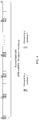
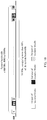
- Uplink resources are allocated by using a resource interlace (interlace) as a basic unit, and resources allocated to each terminal are at least one resource interlace (interlace). As shown in FIG.
- each resource interlace (interlace) consists of 10 resource blocks (Resource Block, RB) that are evenly distributed in the entire bandwidth, and there are 10 RBs between every two adjacent RBs in each resource interlace (interlace). This ensures that each interlace has a frequency spacing (bandwidth spacing between RBs on two ends) of 91 RBs, approximately 16.38 MHz, which is greater than 80% of the 20 MHz system bandwidth.
- the prior-art resource interlace (interlace) structure includes constantly 10 RBs, but is not flexible enough.
- resources are wasted.
- next-generation new radio (New Radio, NR) technologies support flexible configuration of a plurality of system bandwidths and subcarrier spacings, and a total quantity of RBs corresponding to a system bandwidth may no longer be an integer multiple of 10.
- the prior-art resource interlace (interlace) solution is unable to implement flexible scheduling of resources.
- embodiments of this application provide a resource allocation method and a related device and system, so that resources can be scheduled flexibly, to better adapt to multi-bandwidth scenarios supported by next-generation new radio technologies.
- a resource allocation method including: allocating, by a base station, a resource group including M (where M ⁇ 2, and M is a positive integer) first resource blocks to a terminal when allocating uplink resources, where an occupancy ratio of a frequency spacing formed by the M first resource blocks to a system bandwidth is greater than a preset threshold.
- the resource group further includes N (where N ⁇ 1, and N is a positive integer) second resource blocks in any frequency domain positions.
- the base station may send resource indication information to the terminal.
- the resource indication information is used to indicate the resource group allocated to the terminal, and the resource indication information includes information about the resource group. It may be understood that to avoid resource collision, the N second resource blocks allocated to the terminal are distributed in any frequency domain positions other than positions of the M first resource blocks.
- the OCB regulation of ETSI may be consulted for selection of the preset threshold herein, so that the OCB requirement of ESTI is met.
- the preset threshold may be set to greater than or equal to 80%. This example is used to merely explain this embodiment of this application without constituting any limitation.
- scheduling of uplink resources can be more flexible while the OCB requirement of ESTI is met.
- the M first resource blocks allocated to the terminal may be one or more pairs of resource blocks from a first resource set, and an occupancy ratio of a frequency spacing between every pair of resource blocks in the first resource set to the system bandwidth is greater than the preset threshold. Specifically, the occupancy ratio of the frequency spacing between every pair of resource blocks in the first resource set to the system bandwidth is greater than the preset threshold, so that the OCB requirement of ESTI is met.
- a plurality of pairs of resource blocks in the first resource set may be allocated in a form of pairs to a plurality of terminals that need to transmit uplink data on an unlicensed frequency band, so that a signal transmission bandwidth of every terminal meets the basic OCB requirement.
- the rest N second resource blocks allocated to the terminal may be distributed in any frequency domain positions. This can maximize flexibility of resource allocation while ensuring that the basic OCB requirement is met.
- the first resource set may be implemented in the following several manners without being limited thereto:
- a same frequency spacing is present between every pair of resource blocks in the first resource set, and the occupancy ratio of the frequency spacing between every pair of resource blocks to the system bandwidth is greater than the preset threshold.
- frequency spacings of the pairs of resource blocks in the first resource set are in descending order, and an occupancy ratio of a smallest frequency spacing to the system bandwidth is greater than the preset threshold.
- first resource set may be alternatively presented in other forms without being limited to the foregoing two implementations, provided that the occupancy ratio of every pair of resource blocks in the first resource set to the system bandwidth is greater than the preset threshold.
- an occupancy ratio of a frequency spacing formed by the N second resource blocks to the system bandwidth may be less than the preset threshold.
- the N second resource blocks may be distributed in intermediate frequency domain positions in the system bandwidth. It may be understood that there are only a limited quantity of resource blocks on two ends of the system bandwidth that can meet the OCB requirement. Therefore, this scheduling manner of distributing the N second resource blocks in the intermediate frequency domain positions can help the base station to allocate the limited resource blocks on the two ends to more terminals that need to transmit uplink data on an unlicensed frequency band.
- an occupancy ratio of a frequency spacing formed by the N second resource blocks to the system bandwidth may be greater than the preset threshold. This means that at least two of the N second resource blocks are distributed on two ends of the system bandwidth.
- the resource indication information may be implemented in the following several manners without being limited thereto:
- the resource indication information may include indexes of the one or more pairs of resource blocks that are allocated to the terminal, in the first resource set. For example, assuming that a 1st pair of resource blocks in the first resource set shown in FIG. 7 are allocated to the terminal, the resource indication information sent to the terminal may include an index "1" of the 1st pair of resource blocks. This example is used to merely explain this embodiment of this application without constituting any limitation.
- the resource indication information further includes indexes of the one or more pairs of resource blocks corresponding to the N second resource blocks, in the first resource set. If the N second resource blocks allocated to the terminal are not resource blocks in the first resource set, the resource indication information further includes resource block numbers of the N second resource blocks.
- the resource indication information may include resource block numbers of the M first resource blocks allocated to the terminal and resource block numbers of the N second resource blocks allocated to the terminal.
- resource blocks in the entire system bandwidth may be numbered, and a specific resource block can be indicated by using a resource block number.
- the resource block number herein may also be referred to as a resource block index.
- the base station when sending the resource indication information, may add the resource indication information to downlink control information (DCI).
- DCI downlink control information
- the base station may add the resource indication information to an uplink grant (UL grant) returned to the terminal.
- the UL grant herein is a type of DCI in a DCI format 0, 0A, 0B, 4, 4A, or 4B.
- the base station may alternatively add the resource indication information to other response messages for the scheduling request, or the base station may alternatively encapsulate the resource indication information into a separate message, and return the message to the terminal.
- This embodiment of this application imposes no limitation on how the resource indication information is sent.
- the M first resource blocks may form K (K ⁇ 1, where K is a positive integer) resource interlace(s), and an occupancy ratio of a frequency spacing formed by the K resource interlace(s) to the system bandwidth is greater than the preset threshold.
- the N second resource blocks may be some of resource blocks in a resource interlace, and the resource interlace to which the N second resource blocks belong is allocated to a plurality of terminals. It should be noted that the N second resource blocks may be from one resource interlace or from a plurality of resource interlace(s).
- the M first resource blocks allocated to the terminal form the K resource interlace(s)
- the occupancy ratio of the frequency spacing formed by the K resource interlace(s) to the system bandwidth is greater than the preset threshold
- the rest N second resource blocks allocated to the terminal are some of resource blocks in the resource interlace
- the resource interlace to which the N second resource blocks belong is split into a plurality of parts that are shared by the plurality of terminals.
- the resource indication information may be implemented in the following several manners without being limited thereto:
- the resource indication information may include any one or more of the following: interlace indexes of the K resource interlace(s), an interlace index of the resource interlace to which the N second resource blocks belong, or resource block indexes of the N second resource blocks in the resource interlace to which the N second resource blocks belong.
- the base station may index, with numbers, resource interlace(s) included in the entire system bandwidth.
- the base station may index, with numbers, resource blocks included in each resource interlace. For example, 10 resource blocks included in each resource interlace are indexed with numbers 0 to 9.
- the resource indication information may further include attribute indication information corresponding to the resource interlace (which is a partial interlace) to which the N second resource blocks belong, to indicate that only some of resource blocks in the resource interlace to which the N second resource blocks belong are allocated to the terminal.
- the resource interlace to which the N second resource blocks belong is split into a plurality of parts, and the plurality of parts are shared by the plurality of terminals.
- the resource indication information may further include resource block numbers of the M first resource blocks allocated to the terminal and resource block numbers of the N second resource blocks allocated to the terminal.
- resource blocks in the entire system bandwidth may be numbered, and a specific resource block can be indicated by using a resource block number.
- the resource block number herein may also be referred to as a resource block index.
- the resource indication information may include interlace indexes of the K resource interlace(s) and resource block numbers of the N second resource blocks.
- This example is merely an implementation of this embodiment of this application without constituting any limitation. In actual application, different implementations may be used.
- the base station when sending the resource indication information, may add the resource indication information to downlink control information (DCI).
- DCI downlink control information
- the base station may add the resource indication information to an uplink grant (UL grant) returned to the terminal.
- the UL grant herein is a type of DCI in a DCI format 0, 0A, 0B, 4, 4A, or 4B.
- the base station may alternatively add the resource indication information to other response messages for the scheduling request, or the base station may alternatively encapsulate the resource indication information into a separate message, and return the message to the terminal.
- This embodiment of this application imposes no limitation on how the resource indication information is sent.
- the K resource interlace(s) may include H resource blocks, where H is a positive integer, and H is divisible by a total quantity of resource blocks that correspond to each of a plurality of transmission bandwidths corresponding to an unlicensed frequency band.
- a complete resource interlace allocated to the terminal may be indicated by using a resource indication value (RIV).
- RIV indication manner may be mainly used to indicate complete resource interlace(s) allocated to the terminal.
- the resource indication manner described previously may be used as a supplement to indicate the rest N second resource blocks allocated to the terminal. Details are not described herein again.
- a network device including a plurality of function modules, configured to correspondingly perform the method provided in any one of the first aspect or the possible implementations of the first aspect.
- a network device configured to perform the resource allocation method described in the first aspect.
- the wireless network device may include a memory, a processor coupled to the memory, a transmitter, and a receiver.
- the transmitter is configured to send a mobile communication signal to another wireless network device, for example, a terminal.
- the receiver is configured to receive a mobile communication signal sent by the another wireless network device, for example, the terminal.
- the memory is configured to store code for implementing the resource allocation method described in the first aspect.
- the processor is configured to execute the program code stored in the memory, to perform the resource allocation method described in any one of the first aspect or the possible implementations of the first aspect.
- a communications system includes a base station and a terminal.
- the base station is configured to allocate a resource group including M (where M ⁇ 2, and M is a positive integer) first resource blocks to the terminal when allocating uplink resources, where an occupancy ratio of a frequency spacing formed by the M first resource blocks to a system bandwidth is greater than a preset threshold, and the resource group further includes N (where N ⁇ 1, and N is a positive integer) second resource blocks in any frequency domain positions.
- the base station is further configured to send resource indication information to the terminal, where the resource indication information is used to indicate the resource group allocated to the terminal and includes information about the resource group.
- the terminal may process a signal based on the resource indication information, for example, modulating to-be-transmitted uplink data onto resources indicated by the resource indication information, and processing frequency multiplexing and resource sharing for a transmit signal.
- the terminal is further configured to send, to the base station, processed uplink data on the resources indicated by the resource indication information.
- the base station may be the network device described in the second aspect or the third aspect.
- the base station may be the base station described in the first aspect.
- a computer readable storage medium stores program code for implementing the resource allocation method described in the first aspect, and the program code includes an executable instruction for running the resource allocation method described in the first aspect.
- scheduling of uplink resources can be more flexible for use of an unlicensed frequency band while the OCB requirement of ESTI is met.
- resource utilization can be improved.
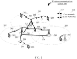
- FIG. 2 shows a wireless communications system 200 according to this application.
- the wireless communications system 200 may work on a licensed frequency band or work on an unlicensed frequency band. It may be understood that use of the unlicensed frequency band can improve a capacity of the wireless communications system 200.
- the wireless communications system 200 includes one or more base stations (Base Station) 201, for example, a NodeB, an eNodeB, or a WLAN access point, one or more terminals (Terminal) 203, and a core network 215.
- the base station 201 may be configured to communicate with the terminal 203 under control of a base station controller (not shown).
- the base station controller may be a part of the core network 230 or be integrated into the base station 201.
- the base station 201 may be configured to transmit control information (control information) or user data (user data) to the core network 215 through a backhaul (backhaul) interface (for example, an S1 interface) 213.
- control information control information
- user data user data
- backhaul backhaul interface
- the base station 201 may wirelessly communicate with the terminal 203 by using one or more base station antennas. Each base station 201 may provide communication coverage for a coverage area 207 corresponding to the base station 201.
- the coverage area 207 corresponding to an access point may be divided into a plurality of sectors (sector), and one sector corresponds to a part of the coverage area (not shown).
- the backhaul link 211 herein may be a wired communication connection or a wireless communication connection.
- the base station 201 may include a base transceiver station (Base Transceiver Station), a radio transceiver, a basic service set (Basic Service Set, BSS), an extended service set (Extended Service Set, ESS), a NodeB, an eNodeB, or the like.
- the wireless communications system 200 may include several different types of base stations 201, for example, a macro base station (macro base station), a micro base station (micro base station), and the like.
- the base station 201 may apply different radio technologies, for example, a cell radio access technology or a WLAN radio access technology.
- the terminals 203 may be distributed in the entire wireless communications system 200, and may be static or moving.
- the terminal 203 may include a mobile device, a mobile station (mobile station), a mobile unit (mobile unit), a radio unit, a remote unit, a user agent, a mobile client, or the like.
- the wireless communications system 200 may be an LTE communications system capable of working on an unlicensed frequency band, for example, an LTE-U system, or may be a 5G communications system, a future new radio communications system, or the like capable of working on an unlicensed frequency band.
- the wireless communications system 200 may use a licensed-assisted access (LAA) scheme to process terminal access on the unlicensed frequency band.
- LAA licensed-assisted access
- a primary cell (Primary Cell) works on a licensed frequency band to transfer key messages and services requiring assured quality of service
- a secondary cell (Secondary Cell) works on an unlicensed frequency band to improve data plane performance.
- the wireless communications system 200 can support multi-carrier (multi-carrier) (waveform signals of different frequencies) operations.
- a multi-carrier transmitter can transmit modulated signals simultaneously on a plurality of carriers.
- every communication connection 205 may carry multi-carrier signals modulated by using different radio technologies. Every modulated signal may be sent on different carriers, and may carry control information (for example, a reference signal and a control channel), overhead information (Overhead Information), data, and the like.
- the wireless communications system 200 may further include a Wi-Fi network.
- the wireless communications system 200 may use a listen before talk (Listen before Talk, LBT) mechanism.
- some terminals 203 may be connected to a Wi-Fi access point 209 through Wi-Fi communication connections 217, to use unlicensed spectrum resources, and some terminals 203 may be connected to the base station 201 through mobile communication connections 205, to use unlicensed spectrum resources.
- LBT listen before Talk
- any device needs to perform listening, to detect whether the frequency band has been occupied, and cannot occupy the frequency band to transmit data unless the frequency band is not busy.
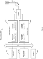
- FIG. 3 shows a terminal 300 according to some embodiments of this application.
- the terminal 300 may include input/output modules (including an audio input/output module 318, a key input module 316, a display 320, and the like), a user interface 302, one or more terminal processors 304, a transmitter 306, a receiver 308, a coupler 310, an antenna 314, and a memory 312. These components may be connected by a bus or in other manners. In FIG. 3 , an example is used in which a bus is used for connection.
- a communications interface 301 may be configured for the terminal 300 to communicate with another communications device, for example, a base station.
- the base station may be a base station 400 shown in FIG. 4 .
- the communications interface 301 may include one or more of a global system for mobile communications (Global System for Mobile Communication, GSM) (2G) communications interface, a wideband code division multiple access (Wideband Code Division Multiple Access, WCDMA) (3G) communications interface, or a long term evolution (Long Term Evolution, LTE) (4G) communications interface, or the like, or may be a communications interface of 4.5G, 5G, or future new radio.
- GSM Global System for Mobile Communication
- WCDMA Wideband Code Division Multiple Access
- LTE Long Term Evolution
- 4G Long Term Evolution
- the terminal 300 may be further equipped with a wired communications interface 301, for example, a local access network (Local Access Network, LAN) interface.
- a local access network Local Access Network, LAN
- the antenna 314 may be configured to: convert electromagnetic energy in a transmission line into an electromagnetic wave in free space, or convert an electromagnetic wave in free space into electromagnetic energy in a transmission line.
- the coupler 310 is configured to: split a mobile communication signal received by the antenna 314 into a plurality of paths, and distribute them to a plurality of receivers 308.
- the transmitter 306 may be configured to perform transmit processing on a signal output by the terminal processor 304, for example, modulating the signal onto a licensed frequency band, or modulating the signal onto an unlicensed frequency band.
- the transmitter 206 may include an unlicensed spectrum transmitter 3061 and a licensed spectrum transmitter 3063.
- the unlicensed spectrum transmitter 3061 may support the terminal 300 in transmitting signals on one or more unlicensed spectrums
- the licensed spectrum transmitter 3063 may support the terminal 300 in transmitting signals on one or more licensed spectrums.
- the receiver 308 may be configured to perform receiving processing on the mobile communication signal received by the antenna 314. For example, the receiver 308 may demodulate a received signal that has been modulated onto an unlicensed frequency band, or demodulate a received signal that has been modulated onto a licensed frequency band.
- the receiver 308 may include an unlicensed spectrum receiver 3081 and a licensed spectrum receiver 3083.
- the unlicensed spectrum receiver 3081 may support the terminal 300 in receiving a signal that is modulated onto an unlicensed spectrum
- the licensed spectrum receiver 3083 may support the terminal 300 in receiving a signal that is modulated onto a licensed spectrum.
- the transmitter 306 and the receiver 308 may be considered as a wireless modem.
- the terminal 300 there may be one or more transmitters 306 and one or more receivers 308.
- the terminal 300 may further include other communications components, for example, a GPS module, a Bluetooth (Bluetooth) module, and a wireless fidelity (Wireless Fidelity, Wi-Fi) module.
- the terminal 300 may further support other wireless communication signals, for example, satellite signals and short-wave signals.
- the terminal 300 may be further equipped with a wired network interface (for example, a LAN interface) to support wired communications.
- the input/output modules may be configured to implement interaction between the terminal 300 and a user or an external environment, and may mainly include the audio input/output module 318, the key input module 316, the display 320, and the like. Specifically, the input/output modules may further include a camera, a touchscreen, a sensor, and the like. The input/output modules all communicate with the terminal processor 304 through the user interface 302.
- the memory 312 is coupled to the terminal processor 304, and configured to store various software programs and/or a plurality of sets of instructions.
- the memory 312 may include a high-speed random access memory, and may also include a non-volatile memory, for example, one or more magnetic disk storage devices, flash memory devices, or other non-volatile solid-state storage devices.
- the memory 312 may store an operating system (referred to briefly as a system below), for example, an embedded operating system such as ANDROID, IOS, WINDOWS, or LINUX.
- the memory 312 may further store a network communication program.
- the network communication program may be used to communicate with one or more peripheral devices, one or more terminal devices, or one or more network devices.
- the memory 312 may further store a user interface program.
- the user interface program may use a graphical operation interface to intuitively display content of an application program, and use input controls such as menus, dialog boxes, and keys to receive control operations of a user on an application program.
- the memory 312 may be configured to store a program for the terminal 300 side to implement a resource allocation method provided in one or more embodiments of this application.
- a resource allocation method provided in one or more embodiments of this application.
- the terminal processor 304 may be configured to read and execute a computer readable instruction. Specifically, the terminal processor 304 may be configured to: invoke the program stored in the memory 312, for example, the program for the terminal 300 side to implement the resource allocation method provided in the one or more embodiments of this application, and execute an instruction included in the program.
- the terminal 300 may be the terminal 203 in the wireless communications system 200 shown in FIG. 2 , and may be implemented as a mobile device, a mobile station (mobile station), a mobile unit (mobile unit), a radio unit, a remote unit, a user agent, a mobile client, or the like.
- terminal 300 shown in FIG. 3 is merely an implementation of the embodiments of this application. In actual application, the terminal 300 may alternatively include more or fewer components. This is not limited herein.
- FIG. 4 shows a base station 400 according to some embodiments of this application.
- the base station 400 may include a communications interface 403, one or more base station processors 401, a transmitter 407, a receiver 409, a coupler 411, an antenna 413, and a memory 405. These components may be connected by a bus or in other manners. In FIG. 4 , an example is used in which a bus is used for connection.
- the communications interface 403 may be configured for the base station 400 to communicate with another communications device, for example, a terminal device or another base station.
- the terminal device may be the terminal 300 shown in FIG. 3 .
- the communications interface 403 may include one or more of a global system for mobile communications (GSM) (2G) communications interface, a wideband code division multiple access (WCDMA) (3G) communications interface, a long term evolution (LTE) (4G) communications interface, or the like, or may be a communications interface of 4.5G, 5G, or future new radio.
- GSM global system for mobile communications
- WCDMA wideband code division multiple access
- LTE long term evolution
- the base station 400 may be further equipped with a wired communications interface 403 to support wired communications.
- a backhaul link between a base station 400 and another base station 400 may be a wired communication connection.
- the antenna 413 may be configured to: convert electromagnetic energy in a transmission line into an electromagnetic wave in free space, or convert an electromagnetic wave in free space into electromagnetic energy in a transmission line.
- the coupler 411 may be configured to: split a mobile communication signal into a plurality of paths, and distribute them to a plurality of receivers 409.
- the transmitter 407 may be configured to perform transmit processing on a signal output by the base station processor 401, for example, modulating the signal onto a licensed frequency band, or modulating the signal onto an unlicensed frequency band.
- the transmitter 407 may include an unlicensed spectrum transmitter 4071 and a licensed spectrum transmitter 4073.
- the unlicensed spectrum transmitter 4071 may support the base station 400 in transmitting signals on one or more unlicensed spectrums
- the licensed spectrum transmitter 4073 may support the base station 400 in transmitting signals on one or more licensed spectrums.
- the receiver 409 may be configured to receive the mobile communication signal received by the antenna 413.
- the receiver 409 may demodulate a received signal that has been modulated onto an unlicensed frequency band, or demodulate a received signal that has been modulated onto a licensed frequency band.
- the receiver 409 may include an unlicensed spectrum receiver 4091 and a licensed spectrum receiver 4093.
- the unlicensed spectrum receiver 4091 may support the base station 400 in receiving a signal that is modulated onto an unlicensed spectrum
- the licensed spectrum receiver 4093 may support the base station 400 in receiving a signal that is modulated onto a licensed spectrum.
- the transmitter 407 and the receiver 409 may be considered as a wireless modem.
- the base station 400 there may be one or more transmitters 407 and one or more receivers 409.
- the memory 405 is coupled to the base station processor 401, and configured to store various software programs and/or a plurality of sets of instructions.
- the memory 405 may include a high-speed random access memory, and may also include a non-volatile memory, for example, one or more magnetic disk storage devices, flash memory devices, or other non-volatile solid-state storage devices.
- the memory 405 may store an operating system (referred to briefly as a system below), for example, an embedded operating system such as uCOS, VxWorks, or RTLinux.
- the memory 405 may further store a network communication program.
- the network communication program may be used to communicate with one or more peripheral devices, one or more terminal devices, or one or more network devices.
- the base station processor 401 may be configured to manage radio channels, establish or tear down a call or communications link, and control cross-region handover of user equipment in a local control region.
- the base station processor 401 may include an administration module/communication module (Administration Module/Communication Module, AM/CM) (a center for line switching and information exchange), a basic module (Basic Module, BM) (configured to complete functions of call processing, signaling processing, radio resource management, radio link management, and circuit maintenance), a transcoder and submultiplexer (Transcoder and SubMultiplexer, TCSM) (configured to complete functions of multiplexing, demultiplexing, and transcoding), and the like.
- Administration Module/communication module (Administration Module/Communication Module, AM/CM) (a center for line switching and information exchange)
- Base Module, BM basic module
- Transcoder and submultiplexer Transcoder and SubMultiplexer, TCSM) (configured to complete functions of multiplexing, demultiplexing, and transcoding
- the base station processor 401 may be configured to read and execute a computer readable instruction. Specifically, the base station processor 401 may be configured to: invoke a program stored in the memory 405, for example, a program for the base station 400 side to implement a resource allocation method provided in one or more embodiments of this application, and execute an instruction included in the program.
- the base station 400 may be the base station 201 in the wireless communications system 200 shown in FIG. 2 , and may be implemented as a base transceiver station, a wireless transceiver, a basic service set (BSS), an extended service set (ESS), a NodeB, an eNodeB, or the like.
- the base station 400 may be implemented as several different types of base stations, for example, a macro base station or a micro base station.
- the base station 400 may apply different radio technologies, for example, a cell radio access technology or a WLAN radio access technology.
- the base station 400 shown in FIG. 4 is merely an implementation of the embodiments of this application. In actual application, the base station 400 may alternatively include more or fewer components. This is not limited herein.
- an embodiment of this application provides a resource allocation method to implement flexible scheduling of resources in allocation of uplink resources while ensuring that the OCB requirement of ETSI is met.
- a main principle of this application may include that resources allocated by a base station to a terminal in allocation of uplink resources can be split into two parts.
- One part of resources may form a frequency spacing whose occupancy ratio to an entire system bandwidth is greater than a preset threshold, and the other part of resources may be flexibly distributed in any positions in the system bandwidth. This can not only ensure a significant frequency spacing, but also make allocation of uplink resources more flexible.
- the OCB regulation of ETSI may be consulted for selection of the preset threshold herein, so that the OCB requirement of ESTI is met. For example, for the 2.4 GHz frequency band and the 5 GHz frequency band, ETSI requires that a signal transmission bandwidth should occupy more than 80% of a system bandwidth. Therefore, the preset threshold may be set to greater than or equal to 80%.
- the one part of resources include M resource blocks (Resource Block, RB), and that the other part of resources include N resource blocks (RB), where M ⁇ 2, N ⁇ 1, and both M and N are positive integers.
- the M resource blocks may be used to ensure that the signal transmission bandwidth meets the OCB requirement, and these resource blocks are referred to as first resource blocks.
- the N resource blocks are used for flexible use of the signal transmission bandwidth, and these resource blocks are referred to as second resource blocks.
- resources allocated to signal include at least two first resource blocks, for example, at least one pair of resource blocks or at least one interlace, and a larger spacing between the two first resource blocks in frequency domain entails a larger signal transmission bandwidth.
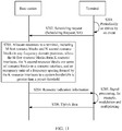
- FIG. 5 shows a resource allocation method according to an embodiment of this application.
- the M first resource blocks allocated to the terminal are one or more pairs of resource blocks in a first resource set.
- An occupancy ratio of a frequency spacing (Frequency Spacing) between every pair of resource blocks in the first resource set to the system bandwidth is greater than the preset threshold.
- Frequency domain positions of the rest N second resource blocks allocated to the terminal are not limited, provided that these positions do not collide with those of the M first resource blocks.
- the method may include the following steps.
- a base station receives a scheduling request (Scheduling Request, SR) sent by a terminal.
- the scheduling request is used to request the base station to allocate uplink transmission resources.
- the terminal may send the scheduling request to the base station periodically. For example, the terminal sends the scheduling request to the base station once every transmission time interval (Transmission Time Interval, TTI).
- TTI Transmission Time Interval
- the terminal may send the scheduling request to the base station when driven by an event. For example, when there is uplink data to be transmitted, the terminal sends the scheduling request to the base station. Arrival of the uplink data herein is an event driving the terminal to send the scheduling request.
- This embodiment of this application imposes no limitation on a mechanism for triggering the terminal to send the scheduling request.
- the base station allocates resources to the terminal, the resources including M first resource blocks and N second resource blocks that are in any frequency domain positions, where the M first resource blocks are one or more pairs of resource blocks in a first resource set, and an occupancy ratio of a frequency spacing between every pair of resource blocks in the first resource set to a system bandwidth is greater than a preset threshold.
- the N second resource blocks allocated to the terminal are distributed in any frequency domain positions other than positions of the M first resource blocks.
- resource blocks in the first resource set may be split into two parts, and the two parts are distributed on or near two ends of the system bandwidth, respectively.
- Two resource blocks included in each pair of resource blocks in the first resource set are from the two parts, respectively, so that the occupancy ratio of the frequency spacing between every pair of resource blocks to the system bandwidth is greater than the preset threshold, meeting the OCB requirement of ESTI.
- a 20 MHz system bandwidth and a 15 kHz subcarrier spacing supported by the 5 GHz frequency band are used as an example.
- the 20 MHz system bandwidth excluding guard bands (approximately 10% of the system bandwidth), there are 100 RBs remaining to serve as a system transmission bandwidth, and each RB includes 12 consecutive subcarriers (180 kHz) in frequency domain.
- each RB includes 12 consecutive subcarriers (180 kHz) in frequency domain.
- it is required that a signal transmission bandwidth occupy more than 80% of the system bandwidth and include at least 89 RBs (89 x 180 kHz 16.02 MHz).
- a pair of resource blocks including RB0 and RB88 ensures a signal transmission bandwidth that meets the minimum OCB requirement, and frequency spacings corresponding to other RB pairs (for example, a pair of RB89 and RB90) after the pair of RB0 and RB88 are even larger.
- the OCB requirement is also met.
- a pair of resource blocks including RB99 and RB11 also ensures a signal transmission bandwidth that meets the minimum OCB requirement, and frequency spacings corresponding to other RB pairs (for example, a pair of RB10 and RB9) before the pair of RB99 and RB11 are even larger.
- the OCB requirement is also met.
- one resource block in two resource blocks included in each pair of resource blocks in the first resource set, one resource block may come from one end of the system bandwidth, that is, RB0 to RB11, and the other resource block may come from the other end of the system bandwidth, that is, RB88 to RB99.
- the base station may randomly select one resource block from one end of the system bandwidth, and randomly select one resource block from the other end of the system bandwidth, so that an occupancy ratio of a frequency spacing between the selected two resource blocks to the system bandwidth is greater than the preset threshold, meeting the OCB requirement.
- a frequency spacing between RB0 and RB89 is 16.20 MHz, whose occupancy ratio to the system bandwidth is greater than 80%. This example is used to merely explain this embodiment of this application without constituting any limitation.
- a same frequency spacing is present between every pair of resource blocks in the first resource set, and the occupancy ratio of the frequency spacing between every pair of resource blocks to the system bandwidth is greater than the preset threshold.
- the first resource set includes 12 pairs of resource blocks.
- RB0 and RB88 form a 1st pair of resource blocks
- RB1 and RB89 form a 2nd pair of resource blocks
- RB2 and RB90 form a 3rd pair of resource blocks
- RB3 and RB91 form a 4th pair of resource blocks, and so on.
- a frequency spacing between every pair of resource blocks is 16.02 MHz, whose occupancy ratio to the system bandwidth is slightly greater than 80%, meeting the OCB requirement.
- the 12 pairs of resource blocks in the first resource set shown in FIG. 7 may be allocated in a form of pairs to a plurality of terminals that need to transmit uplink data on an unlicensed frequency band.
- the base station may process the rest 76 resource blocks (RB12 to RB87) other than the 12 pairs of resource blocks in a prior-art resource scheduling manner (for example, an uplink resource scheduling manner in LTE). This can maximize flexibility of resource allocation and improve resource utilization while ensuring that the basic OCB requirement is met.
- FIG. 7 is merely an embodiment of the first resource set.
- a frequency spacing between a pair of resource blocks may be larger, without being limited to 16.02 MHz.
- the first resource set includes 10 pairs of resource blocks.
- RB0 and RB90 form a 1st pair of resource blocks
- RB1 and RB91 form a 2nd pair of resource blocks
- RB2 and RB92 form a 3rd pair of resource blocks, and so on.
- a frequency spacing between every pair of resource blocks is 16.38 MHz, occupying more than 80% of the system bandwidth. This embodiment of this application imposes no limitation on a specific value of the frequency spacing between each pair of resource blocks in the first resource set.
- implementation of the foregoing first implementation is a process similar to the foregoing process. Details are not described herein again.
- frequency spacings of the pairs of resource blocks in the first resource set are in descending order, and an occupancy ratio of a smallest frequency spacing to the system bandwidth is greater than the preset threshold.
- the first resource set includes six pairs of resource blocks.
- RB0 and RB99 form a 1st pair of resource blocks
- RB1 and RB98 form a 2nd pair of resource blocks
- RB2 and RB97 form a 3rd pair of resource blocks
- RB3 and RB96 form a 4th pair of resource blocks, and so on.
- a frequency spacing between the 1st pair of resource blocks is 18 MHz
- a frequency spacing between the 2nd pair of resource blocks is 17.82 MHz
- a frequency spacing between the 3rd pair of resource blocks is 17.64 MHz, which are in descending order.
- a frequency spacing between a 6th pair of resource blocks is the smallest 16.02 MHz, occupying slightly more than 80% of the system bandwidth, meeting the OCB requirement.
- the six pairs of resource blocks shown in FIG. 9 may be allocated to a plurality of terminals that need to transmit uplink data on an unlicensed frequency band.
- the base station may process the rest 88 resource blocks (RB6 to RB93) other than the six pairs of resource blocks in a prior-art resource scheduling manner (for example, an uplink resource scheduling manner in LTE). This can maximize flexibility of resource allocation and improve resource utilization while ensuring that the basic OCB requirement is met.
- a difference between frequency spacings corresponding to any two adjacent pairs of resource blocks is two RBs.
- a frequency spacing between the 1st pair of resource blocks is 100 RBs
- a frequency spacing between the 2nd pair of resource blocks is 98 RBs
- a frequency spacing between the 3rd pair of resource blocks is 96 RBs.
- FIG. 9 is merely an embodiment of implementation of the first resource set without constituting any limitation. In actual application, the first resource set may be different.
- the first resource set includes three pairs of resource blocks.
- RB0 and RB99 form a 1st pair of resource blocks
- RB2 and RB97 form a 2nd pair of resource blocks
- RB3 and RB96 form a 3rd pair of resource blocks.
- a difference between frequency spacings corresponding to the 1st pair of resource blocks and the 2nd pair of resource blocks is four RBs
- a difference between frequency spacings corresponding to the 2nd pair of resource blocks and the 3rd pair of resource blocks is two RBs.
- implementation of the foregoing second implementation is a process similar to the foregoing process. Details are not described herein again.
- the first resource set may be alternatively presented in other forms without being limited to the foregoing two implementations, provided that the occupancy ratio of every pair of resource blocks in the first resource set to the system bandwidth is greater than the preset threshold.
- the first resource set includes the following several pairs of resource blocks: a 1st pair of resource blocks including RB0 and RB89, a 2nd pair of resource blocks including RB1 and RB88, and a 3rd pair of resource blocks including RB3 and RB92. It may be learned that the first resource set including the three pairs of resource blocks does not match the first implementation or the first implementation but still meets the OCB requirement.
- the base station is not allowed to add uplink transmission signals of a plurality of terminals to one pair of resource blocks.
- a plurality of terminals need to share a resource and signal interference can be avoided on the shared resource.
- the one or more pairs of resource blocks allocated by the base station to different terminals may coincide.
- N second resource blocks The following describes the N second resource blocks. It may be understood that the one or more pairs of first resource blocks allocated to the terminal are used to meet the OCB requirement of ESTI, and positions of the rest N second resource blocks allocated to the terminal may not be limited in frequency domain.
- an occupancy ratio of a frequency spacing formed by the N second resource blocks to the system bandwidth may be greater than the preset threshold. This means that at least two of the N second resource blocks are distributed on two ends of the system bandwidth.
- an occupancy ratio of a frequency spacing formed by the N second resource blocks to the system bandwidth may be less than the preset threshold.
- the N second resource blocks may be distributed in intermediate frequency domain positions in the system bandwidth. It may be understood that there are only a limited quantity of resource blocks on two ends of the system bandwidth that can meet the OCB requirement. Therefore, this scheduling manner of distributing the N second resource blocks in the intermediate frequency domain positions can help the base station to allocate the limited resource blocks on the two ends to more terminals that need to transmit uplink data on an unlicensed frequency band.
- the base station may further schedule resources in the intermediate frequency domain positions in a prior-art resource scheduling manner (for example, an uplink resource scheduling manner in LTE).
- the base station returns resource indication information to the terminal, where the resource indication information is used to indicate the resources allocated by the base station to the terminal, and includes information about the resource group.
- the base station may add the resource indication information to downlink control information (Downlink Control Information, DCI).
- DCI Downlink Control Information
- a new field may be added to the DCI.
- the field is used to indicate the one or more pairs of resource blocks allocated to the terminal, and content of the newly-added field may be indexes (index) of the one or more pairs of resource blocks. For example, an index "1" indicates a pair of resource blocks including RB0 and RB99. This example is used to merely explain this embodiment of this application without constituting any limitation.
- the base station may use a related field for resource indication in an existing DCI format, for example, an RB resource assignment (Resource block assignment) field, to indicate the N second resource blocks.
- RB resource assignment Resource block assignment
- the base station may add the resource indication information to an uplink grant (UL grant for short) returned to the terminal.
- the UL grant herein is a type of DCI in a DCI format 0, 0A, 0B, 4, 4A, or 4B.
- the base station may alternatively add the resource indication information to other response messages for the scheduling request, or the base station may alternatively encapsulate the resource indication information into a separate message, and return the message to the terminal.
- This embodiment of this application imposes no limitation on how the resource indication information is sent.
- the resource indication information may include indexes of the one or more pairs of resource blocks that are allocated to the terminal, in the first resource set. For example, assuming that a 1st pair of resource blocks in the first resource set shown in FIG. 7 are allocated to the terminal, the resource indication information sent to the terminal may include an index "1" of the 1st pair of resource blocks. This example is used to merely explain this embodiment of this application without constituting any limitation.
- the resource indication information further includes indexes of the one or more pairs of resource blocks corresponding to the N second resource blocks, in the first resource set. If the N second resource blocks allocated to the terminal are not resource blocks in the first resource set, the resource indication information further includes resource block numbers of the N second resource blocks.
- the resource indication information may include resource block numbers of the M first resource blocks allocated to the terminal and resource block numbers of the N second resource blocks allocated to the terminal.
- resource blocks in the entire system bandwidth may be numbered, and a specific resource block can be indicated by using a resource block number.
- the resource block number herein may also be referred to as a resource block index.
- the terminal may process a signal based on the resource indication information, for example, modulating to-be-transmitted uplink data onto the resources indicated by the resource indication information, and processing frequency multiplexing and resource sharing for a transmit signal.
- the terminal sends, to the base station, processed uplink data on the resources indicated by the resource indication information.
- the M first resource blocks allocated to the terminal are the one or more pairs of resource blocks in the first resource set, the occupancy ratio of the frequency spacing between every pair of resource blocks in the first resource set to the system bandwidth is greater than the preset threshold, and the rest N second resource blocks allocated to the terminal may be distributed in any frequency domain positions. In this way, resource scheduling can be more flexible while the OCB requirement of ESTI is met.
- FIG. 11 shows a resource allocation method according to another embodiment of this application.
- one resource interlace or some resource interlace(s) may be split, so that a plurality of terminals share one complete resource interlace. In this way, resource configuration is more flexible, and resource utilization is improved.
- the method may include the following steps.
- a base station receives a scheduling request (SR) sent by the terminal.
- the scheduling request is used to request the base station to allocate uplink transmission resources.
- the terminal may send the scheduling request to the base station periodically. For example, the terminal sends the scheduling request to the base station once every transmission time interval (TTI).
- the terminal may send the scheduling request to the base station when driven by an event. For example, when there is uplink data to be transmitted, the terminal sends the scheduling request to the base station. Arrival of the uplink data herein is an event driving the terminal to send the scheduling request.
- This embodiment of this application imposes no limitation on a mechanism for triggering the terminal to send the scheduling request.
- the base station allocates resources to the terminal, the resources including M first resource blocks and N second resource blocks that are in any frequency domain positions, where the M first resource blocks form K (where K ⁇ 1, and K is a positive integer) resource interlace(s), and an occupancy ratio of a frequency spacing formed by the K resource interlace(s) to a system bandwidth is greater than the preset threshold; and the N second resource blocks are some of resource blocks in a resource interlace, and the resource interlace to which the N second resource blocks belong is allocated to a plurality of terminals.
- the N second resource blocks are a partial resource interlace (partial interlace).
- a quantity of resource blocks allocated by the base station to the terminal can be more flexible, without necessarily being an integer quantity of resource interlace(s).
- the resource interlace to which the N second resource blocks belong may be shared by the plurality of terminals. This can improve resource utilization.
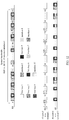
- a 20 MHz system bandwidth and a 15 kHz subcarrier spacing supported by the 5 GHz frequency band are used as an example.
- the 20 MHz system bandwidth excluding guard bands (approximately 10% of the system bandwidth), there are 100 RBs remaining to serve as a system transmission bandwidth.
- the transmission bandwidth includes 10 resource interlace(s) (interlace). It should be understood that an occupancy ratio of a frequency spacing corresponding to every resource interlace to the system bandwidth meets the OCB requirement of ESTI.
- N RB Physical Uplink Shared Channel
- N RB 2 x x 3 y x 5 z
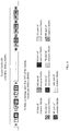
- a resource interlace 1 is allocated to a terminal 1, and a resource interlace 3 is allocated to a terminal.
- a complete resource interlace 2 is split into two parts. A first part is ⁇ RB1, RB11, RB51, RB61, RB71 ⁇ , and a second part is ⁇ RB21, RB31, RB41, RB81, RB91 ⁇ . The first part is allocated to the terminal 1, and the second part is allocated to the terminal 2.
- the resource interlace 1 and the resource interlace 3 may be used to ensure that transmission bandwidths for uplink signals of the terminal 1 and the terminal 2 comply with the OCB regulation of ESTI.
- the resource interlace 2 is shared by the terminal 1 and the terminal 2, improving resource utilization.
- the M (actually 10) first resource blocks allocated to the terminal 1 form the resource interlace 1
- the N (actually 5) second resource blocks allocated to the terminal 1 are some of resource blocks, namely, the first part, of the resource interlace 2.
- the N second resource blocks may be from one interlace. Refer to the terminal 1 in FIG. 12 .
- the N second resource blocks may alternatively be from a plurality of interlace(s). For example, assuming that 18 RBs are allocated to a terminal 3, a resource interlace 5 may be allocated to the terminal 3, ⁇ RB3, RB13, RB23, RB33, RB43 ⁇ in a resource interlace 4 are allocated to the terminal 3, and ⁇ RB5, RB15, RB35 ⁇ in a resource interlace 6 are also allocated to a terminal 5.
- the N (actually 8) second resource blocks allocated to the terminal 3 are from these two resource interlace(s): the resource interlace 4 and the resource interlace 6. This example is used to merely explain this embodiment of this application without constituting any limitation.
- resources may be allocated as a combination of a complete resource interlace (interlace) and a partial resource interlace (partial interlace).
- resource allocated to the terminal may be a complete resource interlace (interlace) alone, or a combination of a complete resource interlace (interlace) and a partial resource interlace (partial interlace).
- the base station returns resource indication information to the terminal, where the resource indication information is used to indicate the resources allocated by the base station to the terminal.
- the base station may add the resource indication information to downlink control information (DCI).
- DCI downlink control information
- a new field may be added to the DCI.
- the field is used to indicate the one or more pairs of resource blocks allocated to the terminal, and content of the newly-added field may be indexes (index) of the one or more pairs of resource blocks. For example, an index "1" indicates a pair of resource blocks including RB0 and RB99. This example is used to merely explain this embodiment of this application without constituting any limitation.
- the base station may use a related field for resource indication in an existing DCI format, for example, an RB resource assignment (Resource block assignment) field, to indicate the N second resource blocks.
- RB resource assignment Resource block assignment
- the base station may add the resource indication information to an uplink grant (UL grant) returned to the terminal.
- UL grant herein is a type of DCI in a DCI format 0, 0A, 0B, 4, 4A, or 4B.
- the base station may alternatively add the resource indication information to other response messages for the scheduling request, or the base station may alternatively encapsulate the resource indication information into a separate message, and return the message to the terminal.
- This embodiment of this application imposes no limitation on how the resource indication information is sent.
- the resource indication information may include any one or more of the following: interlace indexes of the K resource interlace(s), an interlace index of the resource interlace to which the N second resource blocks belong, or resource block indexes of the N second resource blocks in the resource interlace to which the N second resource blocks belong.
- the base station may index, with numbers, resource interlace(s) included in the entire system bandwidth.
- the resource interlace 1 to the resource interlace 10 in FIG. 12 may be indexed with numbers 1 to 10.
- the base station may index, with numbers, resource blocks included in each resource interlace.
- 10 resource blocks included in each resource interlace in FIG. 12 are indexed with numbers 0 to 9.
- the terminal 1 in FIG. 12 is used as an example for description.
- Resources allocated to the terminal 1 include resource blocks in the resource interlace 1 and the first part of resource blocks in the resource interlace 2.
- the resource indication information for the terminal 1 may include an interlace index "1" of the resource interlace 1, an interlace index "2" of the resource interlace 2, and indexes "0" (RB1), "1" (RB11), “6” (RB51), “7” (RB61), and “8” (RB71) of the first part of resource blocks in the resource interlace 2.
- the resource indication information may further include attribute indication information corresponding to the resource interlace (which is a partial interlace) to which the N second resource blocks belong, to indicate that only some of resource blocks in the resource interlace to which the N second resource blocks belong are allocated to the terminal.
- the resource interlace to which the N second resource blocks belong is split into a plurality of parts, and the plurality of parts are shared by the plurality of terminals.
- the resource indication information may further include resource block numbers of the M first resource blocks allocated to the terminal and resource block numbers of the N second resource blocks allocated to the terminal.
- resource blocks in the entire system bandwidth may be numbered, and a specific resource block can be indicated by using a resource block number.
- the resource block number herein may also be referred to as a resource block index.
- the resource indication information may include interlace indexes of the K resource interlace(s) and resource block numbers of the N second resource blocks.
- This example is merely an implementation of this embodiment of this application without constituting any limitation. In actual application, different implementations may be used.
- the terminal may process a signal based on the resource indication information, for example, modulating to-be-transmitted uplink data onto the resources indicated by the resource indication information, and processing frequency multiplexing and resource sharing for a transmit signal.
- the terminal sends, to the base station, processed uplink data on the resources indicated by the resource indication information.
- the M first resource blocks allocated to the terminal form the K resource interlace(s)
- the occupancy ratio of the frequency spacing formed by the K resource interlace(s) to the system bandwidth is greater than the preset threshold
- the rest N second resource blocks allocated to the terminal are some of resource blocks in the resource interlace
- the resource interlace to which the N second resource blocks belong is split into a plurality of parts that are shared by the plurality of terminals.
- the K resource interlace(s) may include H resource blocks, where H is a positive integer, and H is divisible by a total quantity of resource blocks that correspond to each of a plurality of transmission bandwidths corresponding to an unlicensed frequency band.
- the 5 GHz frequency band is used as an example.
- system bandwidths that can be supported include 20 MHz, 40 MHz, 80 MHz, 160 MHz, and the like, and selectable subcarrier spacings include 15 kHz, 60 kHz, and the like.
- transmission bandwidths corresponding to these system bandwidth scenarios may be 100 RBs, 200 RBs, 400 RBs, and 800 RBs, respectively.
- These system bandwidth scenarios require that a bandwidth for occupation by signals be greater than 89 RBs, 178 RBs, 356 RBs, and 712 RBs, respectively, while the OCB requirement of ESTI is met (80% of the system bandwidth is occupied).
- Resource blocks in a resource interlace (interlace) are evenly distributed in the entire transmission bandwidth. Therefore, there are the following several resource interlace (interlace) structures that are compatible with the foregoing system bandwidth scenarios:
- quantities of resource blocks included in the two resource interlace(s) in (1) and (2) are both divisible by total quantities of resource blocks corresponding to the foregoing system bandwidths, so that the base station can use a resource interlace as a resource scheduling unit.
- transmission bandwidths corresponding to the foregoing system bandwidth scenarios may be 25 RBs, 50 RBs, 100 RBs, and 200 RBs, respectively. These system bandwidth scenarios require that a bandwidth for occupation by signals be greater than 23 RBs, 45 RBs, 89 RBs, and 178 RBs, respectively, while the OCB requirement of ESTI is met (80% of the system bandwidth is occupied).
- Resource blocks in a resource interlace (interlace) are evenly distributed in the entire transmission bandwidth. Therefore, a resource interlace (interlace) structure that is compatible with the foregoing system bandwidth scenarios may be as follows: Each resource interlace includes 25 RBs. In the foregoing system bandwidth scenarios, bandwidths occupied by one resource interlace are 25 RBs, 49 RBs, 97 RBs, and 193 RBs, respectively.
- uplink resources on the 5 GHz frequency band may be allocated in the following two schemes:
- the K resource interlace(s) allocated to the terminal may include a plurality of resource interlace(s) with different structures, and the resource indication information may further include type information of the plurality of resource interlace(s) with different structures.
- the 60 GHz frequency band is used as an example.
- system bandwidths that can be supported include 500 MHz, 1 GHz, 2 GHz, and the like, and selectable subcarrier spacings include 480 kHz, 960 kHz (only supported when the system bandwidth is 2 GHz), and the like.
- uplink resources on the 60 GHz frequency band may be allocated by using a fixed 6 RBs/interlace scheme (where each resource interlace includes six RBs).
- a complete resource interlace allocated to the terminal may be indicated by using a resource indication value (Resource Indication Value, RIV).
- RIV Resource Indication Value
- N RB UL is the system transmission bandwidth
- a resource interlace represented by this set is the 1st resource interlace in FIG. 7 .
- Two resource interlace(s) represented by the foregoing two sets are the 1st resource interlace and the 2nd resource interlace in FIG. 7 .
- this RIV indication manner may be mainly used to indicate complete resource interlace(s) allocated to the terminal.
- the resource indication manner described previously may be used as a supplement to indicate the rest N second resource blocks allocated to the terminal. Details are not described herein again.
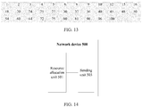
- FIG. 14 shows a network device according to an embodiment of this application.
- the network device 500 may be the base station in the foregoing method embodiments, and may be configured to: receive a scheduling request of a terminal, and allocate uplink signal transmission resources to the terminal on an unlicensed frequency band.
- the network device 500 may include a resource allocation unit 501 and a sending unit 503.
- the resource allocation unit 501 may be configured to allocate a resource group including M first resource blocks to the terminal when allocating uplink resources, where an occupancy ratio of a frequency spacing formed by the M first resource blocks to a system bandwidth is greater than a preset threshold, and the resource group further includes N second resource blocks in any frequency domain positions, where M ⁇ 2, N ⁇ 1, and both M and N are positive integers.
- the sending unit 503 may be configured to send resource indication information to the terminal, where the resource indication information is used to indicate the resource group allocated to the terminal and includes information about the resource group.
- the M first resource blocks are used to comply with the OCB regulation of ESTI, and the N second resource blocks are used to implement flexible resource scheduling.
- the resources allocated by the resource allocation unit 501 to the terminal may include the following two cases.
- the M first resource blocks are one or more pairs of resource blocks in a first resource set, and an occupancy ratio of a frequency spacing between every pair of resource blocks in the first resource set to the system bandwidth is greater than the preset threshold.
- a same frequency spacing is present between every pair of resource blocks in the first resource set, and the occupancy ratio of the frequency spacing between every pair of resource blocks to the system bandwidth is greater than the preset threshold.
- frequency spacings of the pairs of resource blocks in the first resource set are in descending order, and an occupancy ratio of a smallest frequency spacing to the system bandwidth is greater than the preset threshold.
- first resource set may be alternatively presented in other forms without being limited to the foregoing two implementations, provided that the occupancy ratio of every pair of resource blocks in the first resource set to the system bandwidth is greater than the preset threshold.
- the one or more pairs of resource blocks allocated to the terminal are used to meet the OCB requirement of ESTI, and positions of the rest N second resource blocks allocated to the terminal are not limited in frequency domain.
- an occupancy ratio of a frequency spacing formed by the N second resource blocks to the system bandwidth may be greater than the preset threshold. This means that at least two of the N second resource blocks are distributed on two ends of the system bandwidth.
- an occupancy ratio of a frequency spacing formed by the N second resource blocks to the system bandwidth may be less than the preset threshold.
- the N second resource blocks may be distributed in intermediate frequency domain positions in the system bandwidth. It may be understood that there are only a limited quantity of resource blocks on two ends of the system bandwidth that can meet the OCB requirement. Therefore, this scheduling manner of distributing the N second resource blocks in the intermediate frequency domain positions can help the base station to allocate the limited resource blocks on the two ends to more terminals that need to transmit uplink data on an unlicensed frequency band.
- the M first resource blocks form K (where K ⁇ 1, and K is a positive integer) resource interlace(s).
- K an occupancy ratio of a frequency spacing formed by the K resource interlace(s) to the system bandwidth is greater than the preset threshold.
- the N second resource blocks are some of resource blocks in a resource interlace, and the resource interlace to which the N second resource blocks belong is allocated to a plurality of terminals.
- the N second resource blocks are a partial resource interlace (partial interlace).
- a quantity of resource blocks allocated by the base station to the terminal can be more flexible, without necessarily being an integer quantity of resource interlace(s).
- the resource interlace to which the N second resource blocks belong may be shared by the plurality of terminals. This can improve resource utilization.
- the resource indication information sent by the sending unit 503 may be specifically implemented as follows:
- the resource indication information may include indexes of the one or more pairs of resource blocks that are allocated to the terminal, in the first resource set. If the N second resource blocks allocated to the terminal are also one or more pairs of resource blocks in the first resource set, the resource indication information further includes indexes of the one or more pairs of resource blocks corresponding to the N second resource blocks, in the first resource set. If the N second resource blocks allocated to the terminal are not resource blocks in the first resource set, the resource indication information further includes resource block numbers of the N second resource blocks.
- the resource indication information may further include resource block numbers of the M first resource blocks allocated to the terminal and resource block numbers of the N second resource blocks allocated to the terminal.
- the resource indication information may include interlace indexes of the K resource interlace(s), an interlace index of the resource interlace to which the N second resource blocks belong, and resource block indexes of the N second resource blocks in the resource interlace to which the N second resource blocks belong.
- the resource indication information may further include attribute indication information corresponding to the resource interlace (which is a partial interlace) to which the N second resource blocks belong, to indicate that only some of resource blocks in the resource interlace to which the N second resource blocks belong are allocated to the terminal.
- the resource interlace to which the N second resource blocks belong is split into a plurality of parts, and the plurality of parts are shared by the plurality of terminals.
- the resource indication information may further include resource block numbers of the M first resource blocks allocated to the terminal and resource block numbers of the N second resource blocks allocated to the terminal.
- the sending unit 503 may send the resource indication information by using the following several implementations.
- the sending unit 503 may add the resource indication information to downlink control information (DCI). Specifically, the sending unit 503 may add a new field to the DCI.
- the field is used to indicate the one or more pairs of resource blocks allocated to the terminal, and content of the newly-added field may be indexes (index) of the one or more pairs of resource blocks. For example, an index "1" indicates a pair of resource blocks including RB0 and RB99. This example is used to merely explain this embodiment of this application without constituting any limitation.
- the sending unit 503 may use a related field for resource indication in an existing DCI format, for example, an RB resource assignment (Resource block assignment) field, to indicate the N second resource blocks.
- RB resource assignment Resource block assignment
- the sending unit 503 may add the resource indication information to an uplink grant (UL grant) returned to the terminal.
- UL grant herein is a type of DCI in a DCI format 0, 0A, 0B, 4, 4A, or 4B.
- the sending unit 503 may alternatively add the resource indication information to other response messages for the scheduling request, or the sending unit 503 may alternatively encapsulate the resource indication information into a separate message, and return the message to the terminal.
- This embodiment of this application imposes no limitation on how the resource indication information is sent by the sending unit 503.
- an embodiment of this application further provides a wireless communications system.
- the wireless communications system may be the wireless communications system 200 shown in FIG. 2 , and may include a base station and a terminal.
- the terminal may be the terminal in the method embodiment corresponding to FIG. 5 or FIG. 11 .
- the base station may be the base station in the method embodiment corresponding to FIG. 5 or FIG. 11 .
- the terminal may be the terminal 300 shown in FIG. 3 .
- the base station may be the base station 400 shown in FIG. 4 , or may be the network device 500 shown in FIG. 14 .
- scheduling of uplink resources can be more flexible for use of an unlicensed frequency band while the OCB requirement of ESTI is met.
- resource utilization can be improved.
- the program may be stored in a computer readable storage medium.
- the storage medium includes any medium that can store program code, such as a ROM, a random access memory RAM, a magnetic disk, or an optical disc.
- the M first resource blocks are composed of K resource interlace(s) (interlace)interlace(s).
- interlace interlace
- the threshold is
- the foregoing second condition N RB UL ⁇ N RB spacing + 1 ⁇ BW RB / BW > threshold is used to control a frequency spacing of an interlace, so that a ratio of the frequency spacing ( ( N RB UL ⁇ N RB spacing + 1) x BW RB ) of an interlace to the system bandwidth BW meets the OCB requirement.
- Table 1 gives examples of interlace structures for different transmission bandwidths in a low-frequency scenario
- Table 2 gives examples of interlace structures for different transmission bandwidths in a high-frequency scenario.
- system bandwidths are different.
- the system bandwidth is set to including but not being limited to 20 MHz, 40 MHz, or 80 MHz; and in the high-frequency scenario, the system bandwidth is set to including but not being limited to 500 MHz or 1 GHz.
- subcarrier spacings are also different.
- the subcarrier spacing is set to including but not being limited to 15 kHz or 60 kHz; and in the high-frequency scenario, the subcarrier spacing is set to including but not being limited to 120 kHz or 240 kHz.
- N RB UL mod N RB interlace 0 and N RB UL ⁇ N RB spacing + 1 ⁇ BW RB / BW > threshold .
- RB number indicates a quantity N RB UL of RBs corresponding to the transmission bandwidth
- subcarrier number indicates a quantity of subcarriers
- interlace structure indicates a quantity N RB interlace of RBs included in each interlace
- the system bandwidth (BW) is 20 MHz
- the subcarrier spacing (subcarrier spacing, SCS) is 15 kHz
- threshold 80%, meeting the OCB requirement.
- N RB UL 110
- BW RB 0.18 MHz.
- each interlace includes five RBs, and a spacing between two adjacent RBs is equal to 22 RBs.
- each interlace includes 10 RBs, and a spacing between two adjacent RBs is equal to 11 RBs.
- each interlace includes 11 RBs, and a spacing between two adjacent RBs is equal to 10 RBs.
- each interlace includes 22 RBs, and a spacing between two adjacent RBs is equal to five RBs.
- each interlace includes 55 RBs, and a spacing between two adjacent RBs is equal to two RBs.
- one or more parameter values included in a 3rd column sequentially correspond to one or more parameter values included in a 4th column (RB spacing), and two corresponding parameters represent a quantity of RBs included in an interlace (interlace structure) and an RB spacing in the interlace (RB spacing), respectively.
- the 3rd column includes five parameter values: 5, 10, 11, 22, and 55
- the 4th column includes five parameter values: 22, 11, 10, 5, and 2.5 in the 3rd column corresponds to 22 in the 4th column, which is the foregoing first interlace structure.
- 10 in the 3rd column corresponds to 11 in the 4th column, which is the foregoing second interlace structure.
- 11 in the 3rd column corresponds to 10 in the 4th column, which is the foregoing third interlace structure.
- 22 in the 3rd column corresponds to 5 in the 4th column, which is the foregoing fourth interlace structure.
- 55 in the 3rd column corresponds to 2 in the 4th column, which is the foregoing fifth interlace structure.
- the system bandwidth is 500 MHz
- the subcarrier spacing is 240 kHz
- threshold 70%
- BW RB 2.88 MHz.
- interlace(s) can be directly obtained by searching Table 2.
- one or more parameter values included in a 3rd column (interlace structure) sequentially correspond to one or more parameter values included in a 4th column (RB spacing), and two corresponding parameters represent a quantity of RBs included in an interlace (interlace structure) and an RB spacing in the interlace (RB spacing), respectively.
- the 3rd column includes seven parameter values: 6, 12, 13, 26, 39, 52, and 78
- the 4th column includes seven parameter values: 26, 13, 12, 6, 4, 3, 2.
- 6 in the 3rd column corresponds to 26 in the fourth column, which is the foregoing first interlace structure.
- 12 in the 3rd column corresponds to 13 in the 4th column, which is the foregoing second interlace structure.
- 13 in the 3rd column corresponds to 12 in the 4th column, which is the foregoing third interlace structure.
- 26 in the 3rd column corresponds to 6 in the 4th column, which is the foregoing fourth interlace structure.
- 39 in the 3rd column corresponds to 4 in the 4th column, which is the foregoing fifth interlace structure.
- 52 in the 3rd column corresponds to 3 in the 4th column, which is the foregoing sixth interlace structure.
- 78 in the 3rd column corresponds to 2 in the 4th column, which is the foregoing seventh interlace structure.
- Table 1 and Table 2 further show interlace structures in scenarios of a plurality of transmission bandwidths and/or a plurality of subcarrier spacings.
- interlace structures for scenarios with a plurality of system bandwidths and/or a plurality of subcarrier spacings are not limited to those given in Table 1 and Table 2, and other values may be used.
- the parameters given in Table 1 or Table 2 may further include other parameters, for example, a bandwidth percent (bandwidth percent). Any deletion, addition, equivalent replacement, improvement, or the like made to the parameters based on Table 1, Table 2, and the technical solutions of this application shall fall within the protection scope of this application.
- All or some of the foregoing embodiments may be implemented by software, hardware, firmware, or any combination thereof.
- the software is used to implement the embodiments, all or some of the embodiments may be implemented in a form of a computer program product.
- the computer program product includes one or more computer instructions. When the computer program instructions are loaded and executed on the computer, all or some of the procedures or functions according to the embodiments of this application are generated.
- the computer may be a general-purpose computer, a dedicated computer, a computer network, or other programmable apparatuses.
- the computer instructions may be stored in a computer readable storage medium or may be transmitted from a computer readable storage medium to another computer readable storage medium.
- the computer instructions may be transmitted from a website, computer, server, or data center to another website, computer, server, or data center in a wired (for example, through a coaxial cable, an optical fiber, or a digital subscriber line (DSL)) or wireless (for example, through infrared, radio, and microwave, or the like) manner.
- the computer readable storage medium may be any usable medium accessible by a computer, or a data storage device, such as a server or a data center, integrating one or more usable media.
- the usable medium may be a magnetic medium (for example, a floppy disk, a hard disk, or a magnetic tape), an optical medium (for example, DVD), a semiconductor medium (for example, a solid state disk Solid State Disk (SSD)), or the like.
- a magnetic medium for example, a floppy disk, a hard disk, or a magnetic tape
- an optical medium for example, DVD
- a semiconductor medium for example, a solid state disk Solid State Disk (SSD)
Landscapes
- Engineering & Computer Science (AREA)
- Signal Processing (AREA)
- Computer Networks & Wireless Communication (AREA)
- Mobile Radio Communication Systems (AREA)
Applications Claiming Priority (3)
| Application Number | Priority Date | Filing Date | Title |
|---|---|---|---|
| CN201710062965 | 2017-01-26 | ||
| CN201710434527.9A CN108366424B (zh) | 2017-01-26 | 2017-06-09 | 一种资源分配方法、相关设备及系统 |
| PCT/CN2018/074220 WO2018137697A1 (fr) | 2017-01-26 | 2018-01-26 | Procédé d'attribution de ressources, système et dispositif associés |
Publications (3)
| Publication Number | Publication Date |
|---|---|
| EP3567955A1 true EP3567955A1 (fr) | 2019-11-13 |
| EP3567955A4 EP3567955A4 (fr) | 2020-01-08 |
| EP3567955B1 EP3567955B1 (fr) | 2021-05-19 |
Family
ID=63010108
Family Applications (1)
| Application Number | Title | Priority Date | Filing Date |
|---|---|---|---|
| EP18745342.8A Active EP3567955B1 (fr) | 2017-01-26 | 2018-01-26 | Procédé d'attribution de ressources, système et dispositif associés |
Country Status (4)
| Country | Link |
|---|---|
| US (1) | US11303418B2 (fr) |
| EP (1) | EP3567955B1 (fr) |
| JP (1) | JP6961001B2 (fr) |
| CN (1) | CN108366424B (fr) |
Cited By (1)
| Publication number | Priority date | Publication date | Assignee | Title |
|---|---|---|---|---|
| EP3764712A4 (fr) * | 2018-09-18 | 2021-05-19 | Guangdong Oppo Mobile Telecommunications Corp., Ltd. | Procédé d'attribution de ressources, dispositif terminal, et dispositif de réseau |
Families Citing this family (13)
| Publication number | Priority date | Publication date | Assignee | Title |
|---|---|---|---|---|
| WO2020029263A1 (fr) * | 2018-08-10 | 2020-02-13 | Oppo广东移动通信有限公司 | Procédé de communication sans fil et dispositif de communication |
| CN109067425B (zh) * | 2018-08-27 | 2020-03-06 | 维沃移动通信有限公司 | 一种降低干扰的方法及装置 |
| CN112655250B (zh) * | 2018-10-31 | 2023-06-27 | Oppo广东移动通信有限公司 | 无线通信的方法、终端设备和网络设备 |
| WO2020144168A1 (fr) * | 2019-01-11 | 2020-07-16 | Telefonaktiebolaget Lm Ericsson (Publ) | Attribution de ressources pour transmissions de liaison montante dans un spectre sans licence |
| CN111556566B (zh) * | 2019-02-11 | 2023-03-31 | 中国移动通信有限公司研究院 | 频域资源确定方法、频域资源调度的指示方法及设备 |
| CN111565457B (zh) * | 2019-02-14 | 2023-11-03 | 华为技术有限公司 | 传输数据的方法和装置 |
| CN111432481B (zh) * | 2019-05-30 | 2022-03-04 | 维沃移动通信有限公司 | 一种资源映射方法及用户设备 |
| US11743887B2 (en) * | 2019-10-15 | 2023-08-29 | Intel Corporation | Resource allocation for physical uplink control channel during initial access in new radio unlicensed |
| US11438862B2 (en) | 2020-05-14 | 2022-09-06 | Qualcomm Incorporated | Methods and apparatus for using interlaced physical resource blocks for positioning measurements |
| CN112153605B (zh) * | 2020-08-25 | 2023-04-18 | 中国电子科技集团公司电子科学研究院 | 近海通信系统时频资源调度方法及装置 |
| WO2022151430A1 (fr) * | 2021-01-15 | 2022-07-21 | 华为技术有限公司 | Procédé de détermination de ressources dans le domaine fréquentiel et dispositif associé |
| CN113630340B (zh) * | 2021-06-22 | 2024-04-05 | 北京邮电大学 | 分配带宽资源的方法、装置、电子设备及介质 |
| CN117354809A (zh) * | 2022-06-24 | 2024-01-05 | 中兴通讯股份有限公司 | 资源调度方法及使用方法、网络设备、终端设备及介质 |
Family Cites Families (18)
| Publication number | Priority date | Publication date | Assignee | Title |
|---|---|---|---|---|
| GB2464987A (en) * | 2008-11-03 | 2010-05-05 | Nec Corp | Methods for designating resource allocation |
| US9054843B2 (en) * | 2012-01-30 | 2015-06-09 | Nokia Solutions And Networks Oy | Search space arrangement for control channel |
| WO2014019202A1 (fr) * | 2012-08-02 | 2014-02-06 | 华为技术有限公司 | Procédé et dispositif de transmission pour canal de commande de liaison descendante physique amélioré |
| US10285167B2 (en) | 2013-09-20 | 2019-05-07 | Qualcomm Incorporated | Uplink resource allocation and transport block size determination over unlicensed spectrum |
| US9743432B2 (en) | 2013-09-23 | 2017-08-22 | Qualcomm Incorporated | LTE-U uplink waveform and variable multi-subframe scheduling |
| US9949275B2 (en) * | 2013-10-01 | 2018-04-17 | Qualcomm Incorporated | Physical uplink control management in LTE/LTE-A systems with unlicensed spectrum |
| US10687218B2 (en) * | 2013-12-03 | 2020-06-16 | Qualcomm Incorporated | Power metric optimization and uplink DM-RS design for LTE/LTE-A uplink transmissions in unlicensed spectrum |
| US10033505B2 (en) * | 2014-07-31 | 2018-07-24 | Qualcomm Incorporated | Transmission of uplink control channels over an unlicensed radio frequency spectrum band |
| US9867187B2 (en) * | 2014-08-04 | 2018-01-09 | Qualcomm Incorporated | Techniques for configuring uplink channel transmissions using shared radio frequency spectrum band |
| WO2016119446A1 (fr) * | 2015-01-27 | 2016-08-04 | 中兴通讯股份有限公司 | Procédé et dispositif pour mettre en œuvre une transmission d'informations de commande de liaison montante |
| WO2016141989A1 (fr) * | 2015-03-12 | 2016-09-15 | Huawei Technologies Co., Ltd. | Adaptation d'un espacement des fréquences de sous-porteuse sur la base d'un indicateur d'efficacité énergétique |
| CN106162889A (zh) * | 2015-04-10 | 2016-11-23 | 中兴通讯股份有限公司 | 一种实现资源分配的方法和装置 |
| US9801175B2 (en) * | 2015-11-06 | 2017-10-24 | Motorola Mobility Llc | Method and apparatus for low latency transmissions |
| US10568081B2 (en) * | 2016-03-21 | 2020-02-18 | Samsung Electronics Co., Ltd. | Scheduling uplink transmissions |
| US9979581B2 (en) * | 2016-04-01 | 2018-05-22 | Mediatek Inc. | Control channel design for eLAA |
| JP6843984B2 (ja) * | 2016-11-01 | 2021-03-17 | エルジー エレクトロニクス インコーポレイティド | 無線通信システムにおいてnr搬送波のサブバンドアグリゲーションを構成する方法及び装置 |
| US20190342874A1 (en) * | 2018-05-04 | 2019-11-07 | Intel Corporation | Interlace-Based Uplink Physical Channel Design for New Radio-Unlicensed (NR-U) |
| WO2019215920A1 (fr) * | 2018-05-11 | 2019-11-14 | 株式会社Nttドコモ | Terminal utilisateur et station de base sans fil |
-
2017
- 2017-06-09 CN CN201710434527.9A patent/CN108366424B/zh active Active
-
2018
- 2018-01-26 EP EP18745342.8A patent/EP3567955B1/fr active Active
- 2018-01-26 JP JP2019540347A patent/JP6961001B2/ja active Active
-
2019
- 2019-07-25 US US16/522,305 patent/US11303418B2/en active Active
Cited By (5)
| Publication number | Priority date | Publication date | Assignee | Title |
|---|---|---|---|---|
| EP3764712A4 (fr) * | 2018-09-18 | 2021-05-19 | Guangdong Oppo Mobile Telecommunications Corp., Ltd. | Procédé d'attribution de ressources, dispositif terminal, et dispositif de réseau |
| US11018837B2 (en) | 2018-09-18 | 2021-05-25 | Guangdong Oppo Mobile Telecommunications Corp., Ltd. | Resource allocation method, terminal device, and network device |
| EP4185053A1 (fr) * | 2018-09-18 | 2023-05-24 | Guangdong Oppo Mobile Telecommunications Corp., Ltd. | Procédé d'attribution de ressources et dispositif terminal |
| US11811704B2 (en) | 2018-09-18 | 2023-11-07 | Guangdong Oppo Mobile Telecommunications Corp., Ltd. | Resource allocation method, terminal device, and network device |
| US11956177B2 (en) | 2018-09-18 | 2024-04-09 | Guangdong Oppo Mobile Telecommunications Corp., Ltd. | Resource allocation method, terminal device, and network device |
Also Published As
| Publication number | Publication date |
|---|---|
| CN108366424B (zh) | 2021-10-26 |
| CN108366424A (zh) | 2018-08-03 |
| JP6961001B2 (ja) | 2021-11-05 |
| US20190349178A1 (en) | 2019-11-14 |
| JP2020507966A (ja) | 2020-03-12 |
| US11303418B2 (en) | 2022-04-12 |
| EP3567955A4 (fr) | 2020-01-08 |
| EP3567955B1 (fr) | 2021-05-19 |
Similar Documents
| Publication | Publication Date | Title |
|---|---|---|
| EP3567955B1 (fr) | Procédé d'attribution de ressources, système et dispositif associés | |
| US11387969B2 (en) | Signal transmission method, related device, and system | |
| US11032804B2 (en) | Techniques for managing transmissions in an unlicensed radio frequency spectrum band | |
| US11218273B2 (en) | Signal transmission method, related device, and system | |
| US20210288852A1 (en) | Guard band indication method and apparatus | |
| CN111108800B (zh) | 一种通信方法和装置 | |
| WO2018137697A1 (fr) | Procédé d'attribution de ressources, système et dispositif associés | |
| EP3429265B1 (fr) | Procédé de gestion de ressources et dispositif associé | |
| US20230088011A1 (en) | Resource configuration method and apparatus, terminal device and network device | |
| EP4022818B1 (fr) | Procédé d'attribution de ressources de fréquence dans un système à large bande | |
| WO2023205954A1 (fr) | Procédé de communication en liaison latérale, dispositif terminal et dispositif de réseau |
Legal Events
| Date | Code | Title | Description |
|---|---|---|---|
| STAA | Information on the status of an ep patent application or granted ep patent |
Free format text: STATUS: THE INTERNATIONAL PUBLICATION HAS BEEN MADE |
|
| PUAI | Public reference made under article 153(3) epc to a published international application that has entered the european phase |
Free format text: ORIGINAL CODE: 0009012 |
|
| STAA | Information on the status of an ep patent application or granted ep patent |
Free format text: STATUS: REQUEST FOR EXAMINATION WAS MADE |
|
| 17P | Request for examination filed |
Effective date: 20190808 |
|
| AK | Designated contracting states |
Kind code of ref document: A1 Designated state(s): AL AT BE BG CH CY CZ DE DK EE ES FI FR GB GR HR HU IE IS IT LI LT LU LV MC MK MT NL NO PL PT RO RS SE SI SK SM TR |
|
| AX | Request for extension of the european patent |
Extension state: BA ME |
|
| A4 | Supplementary search report drawn up and despatched |
Effective date: 20191206 |
|
| RIC1 | Information provided on ipc code assigned before grant |
Ipc: H04W 72/04 20090101AFI20191202BHEP |
|
| DAV | Request for validation of the european patent (deleted) | ||
| DAX | Request for extension of the european patent (deleted) | ||
| REG | Reference to a national code |
Ref country code: DE Ref legal event code: R079 Ref document number: 602018017371 Country of ref document: DE Free format text: PREVIOUS MAIN CLASS: H04W0072040000 Ipc: H04L0005000000 |
|
| GRAP | Despatch of communication of intention to grant a patent |
Free format text: ORIGINAL CODE: EPIDOSNIGR1 |
|
| STAA | Information on the status of an ep patent application or granted ep patent |
Free format text: STATUS: GRANT OF PATENT IS INTENDED |
|
| RIC1 | Information provided on ipc code assigned before grant |
Ipc: H04L 5/00 20060101AFI20201112BHEP Ipc: H04W 72/04 20090101ALI20201112BHEP |
|
| INTG | Intention to grant announced |
Effective date: 20201202 |
|
| GRAS | Grant fee paid |
Free format text: ORIGINAL CODE: EPIDOSNIGR3 |
|
| GRAA | (expected) grant |
Free format text: ORIGINAL CODE: 0009210 |
|
| STAA | Information on the status of an ep patent application or granted ep patent |
Free format text: STATUS: THE PATENT HAS BEEN GRANTED |
|
| AK | Designated contracting states |
Kind code of ref document: B1 Designated state(s): AL AT BE BG CH CY CZ DE DK EE ES FI FR GB GR HR HU IE IS IT LI LT LU LV MC MK MT NL NO PL PT RO RS SE SI SK SM TR |
|
| REG | Reference to a national code |
Ref country code: GB Ref legal event code: FG4D |
|
| REG | Reference to a national code |
Ref country code: CH Ref legal event code: EP |
|
| REG | Reference to a national code |
Ref country code: DE Ref legal event code: R096 Ref document number: 602018017371 Country of ref document: DE |
|
| REG | Reference to a national code |
Ref country code: AT Ref legal event code: REF Ref document number: 1395046 Country of ref document: AT Kind code of ref document: T Effective date: 20210615 |
|
| REG | Reference to a national code |
Ref country code: IE Ref legal event code: FG4D |
|
| REG | Reference to a national code |
Ref country code: LT Ref legal event code: MG9D |
|
| REG | Reference to a national code |
Ref country code: AT Ref legal event code: MK05 Ref document number: 1395046 Country of ref document: AT Kind code of ref document: T Effective date: 20210519 |
|
| REG | Reference to a national code |
Ref country code: NL Ref legal event code: MP Effective date: 20210519 |
|
| PG25 | Lapsed in a contracting state [announced via postgrant information from national office to epo] |
Ref country code: FI Free format text: LAPSE BECAUSE OF FAILURE TO SUBMIT A TRANSLATION OF THE DESCRIPTION OR TO PAY THE FEE WITHIN THE PRESCRIBED TIME-LIMIT Effective date: 20210519 Ref country code: HR Free format text: LAPSE BECAUSE OF FAILURE TO SUBMIT A TRANSLATION OF THE DESCRIPTION OR TO PAY THE FEE WITHIN THE PRESCRIBED TIME-LIMIT Effective date: 20210519 Ref country code: LT Free format text: LAPSE BECAUSE OF FAILURE TO SUBMIT A TRANSLATION OF THE DESCRIPTION OR TO PAY THE FEE WITHIN THE PRESCRIBED TIME-LIMIT Effective date: 20210519 Ref country code: BG Free format text: LAPSE BECAUSE OF FAILURE TO SUBMIT A TRANSLATION OF THE DESCRIPTION OR TO PAY THE FEE WITHIN THE PRESCRIBED TIME-LIMIT Effective date: 20210819 Ref country code: AT Free format text: LAPSE BECAUSE OF FAILURE TO SUBMIT A TRANSLATION OF THE DESCRIPTION OR TO PAY THE FEE WITHIN THE PRESCRIBED TIME-LIMIT Effective date: 20210519 |
|
| PG25 | Lapsed in a contracting state [announced via postgrant information from national office to epo] |
Ref country code: LV Free format text: LAPSE BECAUSE OF FAILURE TO SUBMIT A TRANSLATION OF THE DESCRIPTION OR TO PAY THE FEE WITHIN THE PRESCRIBED TIME-LIMIT Effective date: 20210519 Ref country code: NO Free format text: LAPSE BECAUSE OF FAILURE TO SUBMIT A TRANSLATION OF THE DESCRIPTION OR TO PAY THE FEE WITHIN THE PRESCRIBED TIME-LIMIT Effective date: 20210819 Ref country code: PL Free format text: LAPSE BECAUSE OF FAILURE TO SUBMIT A TRANSLATION OF THE DESCRIPTION OR TO PAY THE FEE WITHIN THE PRESCRIBED TIME-LIMIT Effective date: 20210519 Ref country code: SE Free format text: LAPSE BECAUSE OF FAILURE TO SUBMIT A TRANSLATION OF THE DESCRIPTION OR TO PAY THE FEE WITHIN THE PRESCRIBED TIME-LIMIT Effective date: 20210519 Ref country code: RS Free format text: LAPSE BECAUSE OF FAILURE TO SUBMIT A TRANSLATION OF THE DESCRIPTION OR TO PAY THE FEE WITHIN THE PRESCRIBED TIME-LIMIT Effective date: 20210519 Ref country code: PT Free format text: LAPSE BECAUSE OF FAILURE TO SUBMIT A TRANSLATION OF THE DESCRIPTION OR TO PAY THE FEE WITHIN THE PRESCRIBED TIME-LIMIT Effective date: 20210920 Ref country code: GR Free format text: LAPSE BECAUSE OF FAILURE TO SUBMIT A TRANSLATION OF THE DESCRIPTION OR TO PAY THE FEE WITHIN THE PRESCRIBED TIME-LIMIT Effective date: 20210820 Ref country code: IS Free format text: LAPSE BECAUSE OF FAILURE TO SUBMIT A TRANSLATION OF THE DESCRIPTION OR TO PAY THE FEE WITHIN THE PRESCRIBED TIME-LIMIT Effective date: 20210919 |
|
| PG25 | Lapsed in a contracting state [announced via postgrant information from national office to epo] |
Ref country code: NL Free format text: LAPSE BECAUSE OF FAILURE TO SUBMIT A TRANSLATION OF THE DESCRIPTION OR TO PAY THE FEE WITHIN THE PRESCRIBED TIME-LIMIT Effective date: 20210519 |
|
| PG25 | Lapsed in a contracting state [announced via postgrant information from national office to epo] |
Ref country code: RO Free format text: LAPSE BECAUSE OF FAILURE TO SUBMIT A TRANSLATION OF THE DESCRIPTION OR TO PAY THE FEE WITHIN THE PRESCRIBED TIME-LIMIT Effective date: 20210519 Ref country code: SM Free format text: LAPSE BECAUSE OF FAILURE TO SUBMIT A TRANSLATION OF THE DESCRIPTION OR TO PAY THE FEE WITHIN THE PRESCRIBED TIME-LIMIT Effective date: 20210519 Ref country code: DK Free format text: LAPSE BECAUSE OF FAILURE TO SUBMIT A TRANSLATION OF THE DESCRIPTION OR TO PAY THE FEE WITHIN THE PRESCRIBED TIME-LIMIT Effective date: 20210519 Ref country code: CZ Free format text: LAPSE BECAUSE OF FAILURE TO SUBMIT A TRANSLATION OF THE DESCRIPTION OR TO PAY THE FEE WITHIN THE PRESCRIBED TIME-LIMIT Effective date: 20210519 Ref country code: SK Free format text: LAPSE BECAUSE OF FAILURE TO SUBMIT A TRANSLATION OF THE DESCRIPTION OR TO PAY THE FEE WITHIN THE PRESCRIBED TIME-LIMIT Effective date: 20210519 Ref country code: EE Free format text: LAPSE BECAUSE OF FAILURE TO SUBMIT A TRANSLATION OF THE DESCRIPTION OR TO PAY THE FEE WITHIN THE PRESCRIBED TIME-LIMIT Effective date: 20210519 Ref country code: ES Free format text: LAPSE BECAUSE OF FAILURE TO SUBMIT A TRANSLATION OF THE DESCRIPTION OR TO PAY THE FEE WITHIN THE PRESCRIBED TIME-LIMIT Effective date: 20210519 |
|
| REG | Reference to a national code |
Ref country code: DE Ref legal event code: R097 Ref document number: 602018017371 Country of ref document: DE |
|
| PLBE | No opposition filed within time limit |
Free format text: ORIGINAL CODE: 0009261 |
|
| STAA | Information on the status of an ep patent application or granted ep patent |
Free format text: STATUS: NO OPPOSITION FILED WITHIN TIME LIMIT |
|
| 26N | No opposition filed |
Effective date: 20220222 |
|
| PG25 | Lapsed in a contracting state [announced via postgrant information from national office to epo] |
Ref country code: IS Free format text: LAPSE BECAUSE OF FAILURE TO SUBMIT A TRANSLATION OF THE DESCRIPTION OR TO PAY THE FEE WITHIN THE PRESCRIBED TIME-LIMIT Effective date: 20210919 Ref country code: AL Free format text: LAPSE BECAUSE OF FAILURE TO SUBMIT A TRANSLATION OF THE DESCRIPTION OR TO PAY THE FEE WITHIN THE PRESCRIBED TIME-LIMIT Effective date: 20210519 |
|
| PG25 | Lapsed in a contracting state [announced via postgrant information from national office to epo] |
Ref country code: IT Free format text: LAPSE BECAUSE OF FAILURE TO SUBMIT A TRANSLATION OF THE DESCRIPTION OR TO PAY THE FEE WITHIN THE PRESCRIBED TIME-LIMIT Effective date: 20210519 |
|
| PG25 | Lapsed in a contracting state [announced via postgrant information from national office to epo] |
Ref country code: MC Free format text: LAPSE BECAUSE OF FAILURE TO SUBMIT A TRANSLATION OF THE DESCRIPTION OR TO PAY THE FEE WITHIN THE PRESCRIBED TIME-LIMIT Effective date: 20210519 |
|
| REG | Reference to a national code |
Ref country code: CH Ref legal event code: PL |
|
| REG | Reference to a national code |
Ref country code: BE Ref legal event code: MM Effective date: 20220131 |
|
| PG25 | Lapsed in a contracting state [announced via postgrant information from national office to epo] |
Ref country code: LU Free format text: LAPSE BECAUSE OF NON-PAYMENT OF DUE FEES Effective date: 20220126 |
|
| PG25 | Lapsed in a contracting state [announced via postgrant information from national office to epo] |
Ref country code: FR Free format text: LAPSE BECAUSE OF NON-PAYMENT OF DUE FEES Effective date: 20220131 Ref country code: BE Free format text: LAPSE BECAUSE OF NON-PAYMENT OF DUE FEES Effective date: 20220131 |
|
| PG25 | Lapsed in a contracting state [announced via postgrant information from national office to epo] |
Ref country code: LI Free format text: LAPSE BECAUSE OF NON-PAYMENT OF DUE FEES Effective date: 20220131 Ref country code: CH Free format text: LAPSE BECAUSE OF NON-PAYMENT OF DUE FEES Effective date: 20220131 |
|
| PG25 | Lapsed in a contracting state [announced via postgrant information from national office to epo] |
Ref country code: IE Free format text: LAPSE BECAUSE OF NON-PAYMENT OF DUE FEES Effective date: 20220126 |
|
| PGFP | Annual fee paid to national office [announced via postgrant information from national office to epo] |
Ref country code: GB Payment date: 20231207 Year of fee payment: 7 |
|
| PG25 | Lapsed in a contracting state [announced via postgrant information from national office to epo] |
Ref country code: MK Free format text: LAPSE BECAUSE OF FAILURE TO SUBMIT A TRANSLATION OF THE DESCRIPTION OR TO PAY THE FEE WITHIN THE PRESCRIBED TIME-LIMIT Effective date: 20210519 Ref country code: CY Free format text: LAPSE BECAUSE OF FAILURE TO SUBMIT A TRANSLATION OF THE DESCRIPTION OR TO PAY THE FEE WITHIN THE PRESCRIBED TIME-LIMIT Effective date: 20210519 |
|
| PGFP | Annual fee paid to national office [announced via postgrant information from national office to epo] |
Ref country code: DE Payment date: 20231205 Year of fee payment: 7 |