EP3567916B1 - Verfahren und vorrichtung zur bandbreitenanzeige - Google Patents
Verfahren und vorrichtung zur bandbreitenanzeige Download PDFInfo
- Publication number
- EP3567916B1 EP3567916B1 EP18794126.5A EP18794126A EP3567916B1 EP 3567916 B1 EP3567916 B1 EP 3567916B1 EP 18794126 A EP18794126 A EP 18794126A EP 3567916 B1 EP3567916 B1 EP 3567916B1
- Authority
- EP
- European Patent Office
- Prior art keywords
- bandwidth
- frequency domain
- virtual
- terminal
- domain position
- Prior art date
- Legal status (The legal status is an assumption and is not a legal conclusion. Google has not performed a legal analysis and makes no representation as to the accuracy of the status listed.)
- Active
Links
Images


Classifications
-
- H—ELECTRICITY
- H04—ELECTRIC COMMUNICATION TECHNIQUE
- H04W—WIRELESS COMMUNICATION NETWORKS
- H04W28/00—Network traffic management; Network resource management
- H04W28/16—Central resource management; Negotiation of resources or communication parameters, e.g. negotiating bandwidth or QoS [Quality of Service]
- H04W28/18—Negotiating wireless communication parameters
- H04W28/20—Negotiating bandwidth
-
- H—ELECTRICITY
- H04—ELECTRIC COMMUNICATION TECHNIQUE
- H04L—TRANSMISSION OF DIGITAL INFORMATION, e.g. TELEGRAPHIC COMMUNICATION
- H04L5/00—Arrangements affording multiple use of the transmission path
- H04L5/0001—Arrangements for dividing the transmission path
- H04L5/0003—Two-dimensional division
- H04L5/0005—Time-frequency
- H04L5/0007—Time-frequency the frequencies being orthogonal, e.g. OFDM(A) or DMT
- H04L5/001—Time-frequency the frequencies being orthogonal, e.g. OFDM(A) or DMT the frequencies being arranged in component carriers
-
- H—ELECTRICITY
- H04—ELECTRIC COMMUNICATION TECHNIQUE
- H04W—WIRELESS COMMUNICATION NETWORKS
- H04W72/00—Local resource management
- H04W72/04—Wireless resource allocation
-
- H—ELECTRICITY
- H04—ELECTRIC COMMUNICATION TECHNIQUE
- H04W—WIRELESS COMMUNICATION NETWORKS
- H04W72/00—Local resource management
- H04W72/04—Wireless resource allocation
- H04W72/044—Wireless resource allocation based on the type of the allocated resource
- H04W72/0453—Resources in frequency domain, e.g. a carrier in FDMA
-
- H—ELECTRICITY
- H04—ELECTRIC COMMUNICATION TECHNIQUE
- H04W—WIRELESS COMMUNICATION NETWORKS
- H04W72/00—Local resource management
- H04W72/20—Control channels or signalling for resource management
- H04W72/23—Control channels or signalling for resource management in the downlink direction of a wireless link, i.e. towards a terminal
-
- H—ELECTRICITY
- H04—ELECTRIC COMMUNICATION TECHNIQUE
- H04L—TRANSMISSION OF DIGITAL INFORMATION, e.g. TELEGRAPHIC COMMUNICATION
- H04L5/00—Arrangements affording multiple use of the transmission path
- H04L5/003—Arrangements for allocating sub-channels of the transmission path
- H04L5/0048—Allocation of pilot signals, i.e. of signals known to the receiver
-
- H—ELECTRICITY
- H04—ELECTRIC COMMUNICATION TECHNIQUE
- H04L—TRANSMISSION OF DIGITAL INFORMATION, e.g. TELEGRAPHIC COMMUNICATION
- H04L5/00—Arrangements affording multiple use of the transmission path
- H04L5/003—Arrangements for allocating sub-channels of the transmission path
- H04L5/0053—Allocation of signalling, i.e. of overhead other than pilot signals
-
- H—ELECTRICITY
- H04—ELECTRIC COMMUNICATION TECHNIQUE
- H04L—TRANSMISSION OF DIGITAL INFORMATION, e.g. TELEGRAPHIC COMMUNICATION
- H04L5/00—Arrangements affording multiple use of the transmission path
- H04L5/0091—Signalling for the administration of the divided path, e.g. signalling of configuration information
- H04L5/0092—Indication of how the channel is divided
-
- H—ELECTRICITY
- H04—ELECTRIC COMMUNICATION TECHNIQUE
- H04L—TRANSMISSION OF DIGITAL INFORMATION, e.g. TELEGRAPHIC COMMUNICATION
- H04L5/00—Arrangements affording multiple use of the transmission path
- H04L5/0091—Signalling for the administration of the divided path, e.g. signalling of configuration information
- H04L5/0094—Indication of how sub-channels of the path are allocated
Definitions
- Embodiments of this application relate to the field of communications technologies, and in particular, to a bandwidth indication method and apparatus.
- a bandwidth capability of a terminal refers to a maximum bandwidth size that can be supported by the terminal. For a given terminal, a bandwidth capability of the terminal is fixed. When a carrier bandwidth is greater than the maximum bandwidth size that can be supported by the terminal, a base station needs to allocate, to the terminal, a segment of bandwidth that is less than or equal to the bandwidth capability of the terminal for the terminal to use.
- the segment of bandwidth allocated by the base station may be referred to as a bandwidth part (Bandwidth Part, BP).
- the terminal transmits physical channel information and physical signal information within the bandwidth part allocated by the base station.
- the terminal may know a size of the carrier bandwidth, or may not know a size of the carrier bandwidth.
- the base station broadcasts the carrier bandwidth in a master information block (Master Information Block, MIB), all terminals in a cell can learn of the carrier bandwidth.
- the base station numbers the carrier bandwidth by using a subcarrier spacing.
- the subcarrier spacing is known to both the base station and the terminals.
- the base station selects a segment of contiguous or noncontiguous physical resource blocks as a BP of one terminal, and indicates the BP of the terminal by indicating the segment of contiguous or noncontiguous physical resources.
- the terminal does not need to know the carrier bandwidth.
- Document R1-167353 "Initial views on the paging on non-anchor PRB for Rel-14 NB-IoT" from NTT DOCOMO, 3GPP TSG RAN WG1 Meeting #86, Gothenburg, Sweden 22nd to 26th August 2016 , Agenda Item: 7.2.11.3, refers to paging PRBs, the exact PRB for one UE to camp on should be determined within the set of paging PRBs on both eNB side and UE side. Considering it is quite difficult to configure exact paging PRB for each UE via signaling, it is more desirable to determine the exact paging PRB based on some rules.
- bandwidth part can be indicated in the DCI (e.g., group common or UE specific) in slot i which can be in effect in next slot or for next n slots. How frequently the BW part is updated is configurable.
- Embodiments of this application provide a bandwidth indication method and apparatus, to provide a solution of indicating, by a base station, an allocated bandwidth part to a terminal when the terminal does not know a carrier bandwidth.
- a bandwidth indication method includes: determining, by a base station, a virtual bandwidth allocated to a terminal, and sending position information of the virtual bandwidth to the terminal, where the virtual bandwidth is a part of a carrier bandwidth, a bandwidth allocated to the terminal falls within the virtual bandwidth, and the position information is used to indicate a position of the virtual bandwidth.
- bandwidth indication can be implemented.
- the position information includes a relative position of the virtual bandwidth relative to a reference frequency domain position.
- the terminal can obtain an actual frequency domain position of the virtual bandwidth based on a baseline frequency domain position and the relative position.
- the base station sends a size of the virtual bandwidth.
- the base station sends the size of the virtual bandwidth in the following manner: sending, by the base station, a first message, where the first message includes a bandwidth set, and the bandwidth set includes at least one bandwidth, or the bandwidth set is predefined; and sending, by the base station, a second message, where the second message is used to indicate that one bandwidth in the bandwidth set is the size of the virtual bandwidth.
- the base station may alternatively send a third message, and the third message is used to indicate the size of the virtual bandwidth.
- a size of the virtual bandwidth is predefined; and there is a correspondence between a carrier frequency and a bandwidth, and the base station determines, based on the correspondence, that a bandwidth corresponding to a used carrier frequency is the size of the virtual bandwidth.
- the relative position may be a first offset value between the reference frequency domain position and a lowest frequency domain position of the virtual bandwidth; or a second offset value between the reference frequency domain position and a highest frequency domain position of the virtual bandwidth; or a third offset value between the reference frequency domain position and a specified frequency domain position of the virtual bandwidth.
- the method further includes: sending, by the base station, resource indication information, where the resource indication information is used to indicate a frequency domain position of a sub-bandwidth occupied by the terminal in the virtual bandwidth; or the resource indication information is used to indicate a frequency domain position of a sub-bandwidth group occupied by the terminal in the virtual bandwidth, the sub-bandwidth group includes n sub-bandwidths, n ⁇ 2, and n is a positive integer.
- a BP allocated to the terminal may be notified based on the position of the virtual bandwidth and the indication of the resource indication information.
- n is predefined, or n is notified by the base station to the terminal, or n is determined based on a maximum bandwidth supported by the terminal.
- the virtual bandwidth may be a cell level, to be specific, the virtual bandwidth may be a bandwidth allocated by the base station to each terminal in a cell; or the virtual bandwidth may alternatively be a terminal level, to be specific, the virtual bandwidth may be a bandwidth allocated by the base station to a specified terminal.
- the base station indicates size information of a frequency domain bandwidth included in a sub-bandwidth at a boundary position of the virtual bandwidth.
- the reference frequency domain position is a synchronization signal block frequency domain position, or a public bandwidth frequency domain position, or a direct current carrier frequency domain position.
- a bandwidth indication method includes: receiving, by a terminal, position information of a virtual bandwidth, and determining a position of the virtual bandwidth based on the position information, where the virtual bandwidth is a part of a carrier bandwidth, a bandwidth allocated by a base station to the terminal falls within the virtual bandwidth, and the position information is used to indicate the position of the virtual bandwidth.
- the bandwidth indication can be implemented.
- the position information includes a relative position of the virtual bandwidth relative to a reference frequency domain position.
- the terminal can obtain an actual frequency domain position of the virtual bandwidth based on a baseline frequency domain position and the relative position.
- the terminal receives a size of the virtual bandwidth.
- the terminal receives the size of the virtual bandwidth in the following manner: receiving, by the terminal, a first message, where the first message includes a bandwidth set, and the bandwidth set includes at least one bandwidth, or the bandwidth set is predefined; and receiving, by the terminal, a second message, where the second message is used to indicate that one bandwidth in the bandwidth set is the size of the virtual bandwidth.
- the terminal may alternatively receive a third message, and the third message is used to indicate the size of the virtual bandwidth.
- a size of the virtual bandwidth is predefined; and there is a correspondence between a carrier frequency and a bandwidth, and the terminal determines, based on the correspondence, that a bandwidth corresponding to a used carrier frequency is the size of the virtual bandwidth.
- the relative position may be a first offset value between the reference frequency domain position and a lowest frequency domain position of the virtual bandwidth; or a second offset value between the reference frequency domain position and a highest frequency domain position of the virtual bandwidth; or a third offset value between the reference frequency domain position and a specified frequency domain position of the virtual bandwidth.
- the method further includes: receiving, by the terminal, resource indication information, determining, by the terminal according to the resource indication information, a frequency domain position of a sub-bandwidth occupied by the terminal in the virtual bandwidth; or determining, by the terminal according to the resource indication information, a frequency domain position of a sub-bandwidth group occupied by the terminal in the virtual bandwidth, where the sub-bandwidth group includes n sub-bandwidths, n ⁇ 2, and n is a positive integer.
- the terminal may learn, based on the position of the virtual bandwidth and the indication of the resource indication information, of a BP allocated by the base station to the terminal within the virtual bandwidth.
- n is predefined, or n is notified by the base station to the terminal, or n is determined based on a maximum bandwidth supported by the terminal.
- the terminal receives size information that is sent by the base station and that is of a frequency domain bandwidth included in a sub-bandwidth at a boundary position of the virtual bandwidth.
- the reference frequency domain position is a synchronization signal block frequency domain position, or a public bandwidth frequency domain position, or a direct current carrier frequency domain position.
- a bandwidth indication apparatus has a function for implementing a behavior of the base station according to any one of the first aspect and the possible designs of the first aspect.
- the function may be implemented by using hardware, or may be implemented by hardware executing corresponding software.
- the hardware or software includes one or more modules corresponding to the foregoing function.
- a bandwidth indication apparatus has a function for implementing a behavior of the base station according to any one of the second aspect and the possible designs of the second aspect.
- the function may be implemented by using hardware, or may be implemented by hardware executing corresponding software.
- the hardware or software includes one or more modules corresponding to the foregoing function.
- a bandwidth indication apparatus includes a transceiver, a memory, a processor, and a bus.
- the memory is configured to store a set of programs.
- the processor is configured to invoke the programs stored in the memory, to perform the method according to any one of the first aspect and the possible designs of the first aspect.
- a bandwidth indication apparatus includes a transceiver, a memory, a processor, and a bus.
- the memory is configured to store a set of programs.
- the processor is configured to invoke the programs stored in the memory, to perform the method according to any one of the second aspect and the possible designs of the second aspect.
- a communications system includes the apparatus according to the third aspect or the fifth aspect and the apparatus according to the fourth aspect or the sixth aspect.
- a computer storage medium is provided.
- the computer storage medium is configured to store a computer program.
- the computer program includes an instruction used to perform the method according to any one of the first aspect and the possible implementations of the first aspect, or any one of the second aspect and the possible implementations of the second aspect.
- an embodiment of this application provides a computer program product including an instruction.
- the computer program product When the computer program product is run on a computer, the computer is enabled to perform the method according to the foregoing aspects.
- a virtual bandwidth is pre-divided, and a frequency domain position that the terminal easily obtains is used as a baseline point.
- the baseline point may also be referred to as a baseline frequency domain position or a specified frequency domain position.
- a base station notifies the terminal of a relative position between the baseline point and the virtual bandwidth. In this way, the terminal may obtain an actual frequency domain position of the virtual bandwidth based on a position of the baseline point and the relative position, thereby implementing bandwidth indication.
- a communications system to which an embodiment of this application is applied includes a base station 101 and terminals 102.
- the base station 101 is an apparatus that is deployed in a radio access network and that is configured to provide a wireless communication function to the terminals 102.
- the base station 101 may include macro base stations, micro base stations, relay stations, access points, and the like in various forms, may be applied to systems of different radio access technologies, for example, to more possible communications systems such as a long term evolution (Long Term Evolution, LTE) system or a 5th generation (5th Generation, 5G) communications system.
- the base station 101 may further be another network device having a base station function, and particularly, may further be a terminal that serves as the base station function in D2D communication.
- the terminal 102 may include various handheld devices, in-vehicle devices, wearable devices, computing devices that have a wireless communication function or other processing devices connected to a wireless modem, and user equipments (User Equipment, UE), mobile stations (Mobile Station, MS), and the like in various forms.
- user equipment User Equipment, UE
- MS Mobile Station
- the concept of carrier bandwidth is equivalent to a system bandwidth.
- a bandwidth allocated by the base station to the terminal may be referred to as a BP.
- the terminal transmits physical channel information or physical signal information by using the BP allocated by the base station.
- the physical channel information includes physical uplink and downlink control channel information and physical uplink and downlink shared channel information.
- a definition of a virtual bandwidth mentioned in the embodiments of this application is first explained.
- the embodiments of this application provide a virtual bandwidth, to help a base station allocate a BP to a terminal.
- the virtual bandwidth is a segment of contiguous bandwidths divided from the carrier bandwidth.
- the virtual bandwidth is less than or equal to the carrier bandwidth.
- a position of the virtual bandwidth in frequency domain can be variable.
- positions of the virtual bandwidth in the frequency domain may be different.
- a size of the virtual bandwidth is a bandwidth occupied by the virtual bandwidth on the carrier bandwidth.
- the virtual bandwidth may be a public level or a user group. To be specific, for all terminals in a cell or a user group, sizes of virtual bandwidths are the same.
- the virtual bandwidth may alternatively be a terminal level. To be specific, sizes of virtual bandwidths of different terminals in a cell may be different.
- a reference frequency domain position described in the embodiments of this application may also be referred to as a specified frequency domain position.
- the specified frequency domain position is a frequency domain position fixed in the carrier bandwidth and can be learned of by a terminal.
- the reference frequency domain position may be a synchronization signal block frequency domain position, or a public bandwidth frequency domain position, or a direct current carrier frequency domain position.
- a baseline point at which the base station allocates a bandwidth is determined, a size of a virtual bandwidth is also determined, and the base station only needs to notify the terminal of a relative position between the baseline point and the virtual bandwidth.
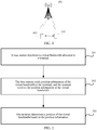
- a specific procedure of a bandwidth indication method is as follows.
- Step 201 The base station determines a virtual bandwidth allocated to the terminal.
- the virtual bandwidth is a part of a carrier bandwidth, and a bandwidth allocated to the terminal falls within the virtual bandwidth.
- Step 202 The base station sends position information of the virtual bandwidth to the terminal, and the terminal receives the position information of the virtual bandwidth.
- the position information is used to indicate a position of the virtual bandwidth.
- the position information includes a relative position of the virtual bandwidth relative to a reference frequency domain position.
- the relative position may be an offset value.
- the relative position is used by the terminal to determine a frequency domain position of the virtual bandwidth based on the reference frequency domain position and the relative position.
- Step 203 The terminal determines the position of the virtual bandwidth based on the position information.
- the terminal determines a BP allocated by the base station to the terminal in the virtual bandwidth.
- manners of determining, by the base station, a size of the virtual bandwidth and notifying the terminal of the size of the virtual bandwidth include but are not limited to the following manners.
- the size of the virtual bandwidth is predefined. To be specific, the size of the virtual bandwidth does not need to be notified by the base station.
- a correspondence between the carrier frequency (or a carrier frequency range) and the size of the virtual bandwidth is preset.
- the base station and the terminal find, based on a used carrier frequency and the correspondence, a bandwidth corresponding to the used carrier frequency as a size of a virtual bandwidth used in a current bandwidth indication.
- the correspondence is shown in Table 1.
- Table 1 Carrier frequency (GHz) f ⁇ 6 6 ⁇ f ⁇ 28 f>28 Bandwidth (MHz) 100 200 400
- the size of the virtual bandwidth is 100 MHz.
- the size of the virtual bandwidth is 200 MHz.
- the size of the virtual bandwidth is 400 MHz.
- one carrier frequency or carrier frequency range corresponds to one bandwidth set.
- a base station side first determines the bandwidth set by using the carrier frequency, and then notifies, by using master information block (Master Information Block, MIB) signaling, or system information block (System Information Block, SIB) signaling, or remaining minimum system information (Remaining Minimum System Information, RMSI) signaling, the terminal of the virtual bandwidth determined by the base station.
- Master Information Block MIB
- system information block System Information Block, SIB
- RMSI remaining Minimum System Information
- the base station sends a first message, the first message carries a bandwidth set, and the bandwidth set includes at least one bandwidth.
- the bandwidth set is predefined.
- the base station sends a second message, and the second message carries indication information and is used to indicate that a bandwidth in the bandwidth set is the size of the virtual bandwidth.
- the first message is radio resource control (Radio Resource Control, RRC) signaling.
- RRC Radio Resource Control
- the base station adds the bandwidth set to the RRC signaling.
- An example of the bandwidth set is ⁇ 50, 100, 150, 200, 400 ⁇ MHz.
- a bandwidth set ⁇ 50, 100, 150, 200, 400 ⁇ MHz is predefined.
- the second message is master information block (Master Information Block, MIB) signaling, or system information block (System Information Block, SIB) signaling, or remaining minimum system information (Remaining Minimum System Information, RMSI) signaling.
- MIB Master Information Block
- SIB System Information Block
- RMSI remaining Minimum System Information
- the base station uses the MIB signaling, or the SIB signaling, or the RMSI signaling to indicate a bandwidth in the bandwidth set as the size of the virtual bandwidth.
- the base station uses three bits to indicate the size of the virtual bandwidth.
- the base station may alternatively directly indicate a specific virtual bandwidth value, such as 100 MHz, by using signaling.
- the base station may use, but not limited to, the following signaling: the RRC signaling, the MIB signaling, the SIB signaling, and the RMSI signaling.
- the size of the virtual bandwidth that is determined by the base station needs to be determined based on a maximum bandwidth supported by the terminal.
- the size of the virtual bandwidth that is determined by the base station may be equal to the maximum bandwidth supported by the terminal.
- the size of the virtual bandwidth is determined, so that signaling overheads of resource allocation performed by the base station is a determined value.
- the signaling overheads of the resource allocation are further related to a resource allocation granularity in the virtual bandwidth.
- the resource allocation granularity refers to a minimum unit for the resource allocation, may be a segment of contiguous or noncontiguous resource units having a fixed bandwidth size, may be an integral number of resource units including physical resource blocks, or an integral number of resource units having fixed bandwidth sizes, or the like.
- the terminal may learn of the size of the virtual bandwidth on which the base station allocates a resource, but the terminal does not know a specific position of the bandwidth allocated by the base station in frequency domain.
- the base station notifies the specific frequency domain position of the allocated bandwidth by using the relative position between the baseline frequency domain position and the virtual bandwidth.
- the relative position may be a frequency domain offset value.
- the relative position may be a first offset value between the reference frequency domain position and a lowest frequency domain position of the virtual bandwidth; or a second offset value between the reference frequency domain position and a highest frequency domain position of the virtual bandwidth; or a third offset value between the reference frequency domain position and a specified frequency domain position of the virtual bandwidth.
- the specified frequency domain position of the virtual bandwidth may be a specified reference frequency domain position in the virtual bandwidth, for example, a minimum resource allocation unit numbered m in the virtual bandwidth, where m ⁇ 0, and m is an integer.
- the resource allocation granularity in the virtual bandwidth refers to a minimum unit for bandwidth allocation.
- a physical resource block Physical Resource Block, PRB
- a resource block group Resource Block Group, RBG
- this embodiment of this application provides a resource allocation granularity of a sub-bandwidth.
- the concept of sub-bandwidth in this embodiment of this application is equivalent to the concept of sub-BP.
- the concept of sub-BP is used for description.
- the virtual bandwidth is divided into N contiguous sub-BPs, and N is a positive integer.
- the BP includes a segment of contiguous PRBs, or the sub-BP is a resource block unit having a fixed bandwidth in frequency domain, or the sub-BP includes a segment of contiguous resource units having a fixed bandwidth.
- a size of the sub-BP refers to a bandwidth occupied by a size of the sub-BP in frequency domain.
- the base station further needs to send the size of the sub-BP and/or the quantity of the sub-BPs to the terminal.
- the sub-BPs are used by the base station to better indicate specified positions occupied by the terminal in the virtual bandwidth.
- the base station further needs to send resource indication information to the terminal.
- the resource indication information is used to indicate a specific frequency domain position of the occupied sub-BP in the BP allocated to the terminal in the virtual bandwidth terminal.
- the base station may further use the resource indication information to indicate a specific frequency domain position of an occupied sub-BP group in the BP allocated to the terminal in the virtual bandwidth.
- the sub-BP group includes n sub-BPs, where n ⁇ 2, and n is a positive integer. A value of n may be predefined. To be specific, quantities of sub-BPs included in sub-BP groups of all terminals in a cell are the same.
- a value of n is notified by the base station to the terminal, for example, by using the MIB signaling, or the SIB signaling, or the RMSI, or the RRC signaling.
- a value of n is related to a bandwidth capability of the terminal.
- the value of n is bound to the maximum bandwidth supported by the terminal or a bandwidth reported by the terminal.
- the maximum bandwidth supported by the terminal is 100 MHz
- the value of n is 2
- the sub-BP group includes two sub-BPs.
- the maximum bandwidth supported by the terminal is 200 MHz
- the value of n is 4
- the sub-BP group includes four sub-BPs.
- the terminal reports that a bandwidth value expected by the terminal is 100 MHz, the value of n is 2, and the sub-BP group includes two sub-BPs.
- the base station notifies the terminal of the size of the virtual bandwidth and the size of the sub-BP in the virtual bandwidth.
- the base station further needs to notify the terminal of the specific positions of the occupied sub-BP in the virtual bandwidth.
- the base station notifies the terminal of the specific position of the occupied sub-BP in the virtual bandwidth in a resource allocation manner 0 (namely, a bitmap) in existing LTE.
- a resource allocation manner 0 namely, a bitmap
- the base station divides the virtual bandwidth into a fixed quantity of sub-BPs based on the size of the sub-BP, for example, into ten sub-BPs, namely, a sub-BP 0, a sub-BP 1, ..., and a sub-BP 9.
- a value of the bitmap indicates whether a corresponding sub-BP is occupied by a resource allocated to the terminal.
- values of the bitmap include 1 and 0.
- the value of the bitmap being 1 indicates that the corresponding sub-BP is occupied by the resource allocated to the terminal. That the reference frequency domain position is a synchronization signal block frequency domain position is used as an example.
- the base station notifies, by using the RRC signaling, the terminal of an offset value between the synchronization signal block frequency domain position and a sub-BP corresponding to a least significant bit or a most significant bit in the bitmap, namely, an offset value between the synchronization signal block frequency domain position and a lowest frequency domain position or a highest frequency domain position of the virtual bandwidth.
- the offset value may be a particular quantity of physical resource blocks, or may be a particular quantity of sub-BPs, or may be a particular quantity of sub-BP groups.
- the base station further needs to notify a position relationship between the reference frequency domain position and the virtual bandwidth.
- the position relationship includes: the reference frequency domain position is in the virtual bandwidth and the reference frequency domain position is at a low frequency domain position or a high frequency domain position of the virtual bandwidth.
- the reference frequency domain position namely, the synchronization signal block frequency domain position is in the virtual bandwidth, and is at a position of the sub-BP 5.
- An offset value between the synchronization signal block frequency domain position and a sub-BP corresponding to the least significant bit in the bitmap is 5
- an offset value between the synchronization signal block frequency domain position and a sub-BP corresponding to the most significant bit in the bitmap is 4, and the value of the bitmap is 1111011011.
- sub-BPs occupied by the resource allocated to the terminal include the sub-BP 0, the sub-BP 1, the sub-BP 2, the sub-BP 3, the sub-BP 4, the sub-BP 5, the sub-BP 8, and the sub-BP 9.
- the reference frequency domain position namely, the synchronization signal block frequency domain position is at the low frequency domain position of the virtual bandwidth, and the value of the bitmap is 1111011011. Therefore, the sub-BPs occupied by the terminal include the sub-BP 0, the sub-BP 1, the sub-BP 2, the sub-BP 3, the sub-BP 4, the sub-BP 5, the sub-BP 8, and the sub-BP 9.
- the reference frequency domain position may alternatively be at the high frequency domain position of the virtual bandwidth.
- the terminal determines an operating bandwidth of the terminal based on the offset value between the reference frequency domain position and the lowest frequency domain position, or the offset value between the reference frequency domain position and the highest frequency domain position, or the offset value between the reference frequency domain position and a specified frequency domain position in the virtual bandwidth and a sub-BP allocation status in the virtual bandwidth.
- the base station may further notify the terminal of the specific position of the occupied sub-BP in the virtual bandwidth in a resource allocation manner 1 or a resource allocation manner 2 in the existing LTE.
- a segment of contiguous bandwidths is allocated to one terminal in the resource allocation manner 2.
- the segment of the contiguous bandwidths occupies log 2 N N + 1 2 bits, where N is a quantity of sub-BPs in the virtual bandwidth.
- the base station in a scenario in which the terminal cannot learn of a size of the carrier bandwidth, can indicate an allocated bandwidth part to the terminal, and can further indicate a sub-BP in the bandwidth part occupied by the terminal.
- the base station when the virtual bandwidth is a public level, the base station further needs to indicate a quantity of unit resource amounts included in a sub-BP at a boundary position of the virtual bandwidth, or a bandwidth size of a boundary sub-BP.
- a quantity of unit resource amounts included in a sub-BP at the boundary position of the virtual bandwidth may be less than P.
- the base station indicates, to the terminal by using signaling, the quantity of unit resource amounts included in the sub-BP at the boundary position of the virtual bandwidth. This help prevent the resource used by the terminal from being beyond the boundary of the virtual bandwidth, and effectively improve accuracy of the resource indication.
- the base station may perform the foregoing indication by using (log 2 P) bits.
- FIG. 5 shows five sub-BPs, namely, a sub-BP m, a sub-BP m+1, ..., and a sub-BP m+5.
- Each sub-BP includes three physical resource blocks, namely, 0, 1, and 2.
- the sub-BP (m+5) is located at the boundary position of the virtual bandwidth, and the sub-BP (m+5) includes only one physical resource block that is less than the quantity 3 of physical resource blocks included in one sub-BP.
- 00 may be used to indicate that the sub-BP (m+5) includes three physical resource blocks
- 01 may be used to indicate that the sub-BP (m+5) includes one physical resource block
- 10 may be used to indicate that the sub-BP (m+5) includes two physical resource blocks.
- a bandwidth size of one sub-BP is 3 MHz, and the size of the virtual bandwidth is 100 MHz, one virtual bandwidth includes 34 sub-BPs, and a size of the last one boundary sub-BP is 1 MHz.
- Indication needs to be performed.
- the base station may perform the indication by using log2Q, where Q is the bandwidth size of the sub-BP. Therefore, two bits may be used to indicate a bandwidth size of a boundary sub-BP, 00 indicates that the bandwidth size of the boundary sub-BP is 3 MHz, 01 indicates that the bandwidth size of the boundary sub-BP is 1 MHz, and 10 indicates that the bandwidth size of the boundary sub-BP is 2 MHz.
- an embodiment of this application further provides a bandwidth indication apparatus 600.
- the bandwidth indication apparatus 600 is configured to perform the bandwidth indication method shown in FIG. 2 .
- the bandwidth indication apparatus 600 includes:
- the position information includes a relative position of the virtual bandwidth relative to a reference frequency domain position.
- the sending unit 602 is further configured to:
- a size of the virtual bandwidth is predefined; and there is a correspondence between a carrier frequency and a bandwidth, and the processing unit is configured to determine, based on the correspondence, that a bandwidth corresponding to a used carrier frequency is the size of the virtual bandwidth.
- the relative position includes:
- the sending unit 602 is further configured to:
- the reference frequency domain position is a synchronization signal block frequency domain position, or a public bandwidth frequency domain position, or a direct current carrier frequency domain position.
- an embodiment of this application further provides a bandwidth indication apparatus 700.
- the bandwidth indication apparatus 700 is configured to perform the bandwidth indication method shown in FIG. 2 .
- the bandwidth indication apparatus 700 includes:
- the position information includes a relative position of the virtual bandwidth relative to a reference frequency domain position.
- the receiving unit 701 is further configured to:
- a size of the virtual bandwidth is predefined; and there is a correspondence between a carrier frequency and a bandwidth, and the terminal determines, based on the correspondence, that a bandwidth corresponding to a used carrier frequency is the size of the virtual bandwidth.
- the relative position includes:
- the receiving unit 701 is further configured to:
- the reference frequency domain position is a synchronization signal block frequency domain position, or a public bandwidth frequency domain position, or a direct current carrier frequency domain position.
- an embodiment of this application further provides a bandwidth indication apparatus 800.
- the bandwidth indication apparatus 800 may be configured to perform the bandwidth indication method shown in FIG. 2 .
- the bandwidth indication apparatus 800 includes a transceiver 801, a processor 802, a memory 803, and a bus 804.
- the processor 802 is connected to the memory 803 by using the bus 804.
- the processor 802 is configured to execute code in the memory 803. When the code is executed, the execution enables the processor 802 to perform the bandwidth indication method shown in FIG. 2 .
- the processor 802 may be a central processing unit (central processing unit, CPU), a network processor (network processor, NP), or a combination of a CPU and an NP.
- CPU central processing unit
- NP network processor
- the processor 802 may further include a hardware chip.
- the foregoing hardware chip may be an application-specific integrated circuit (application-specific integrated circuit, ASIC), a programmable logic device (programmable logic device, PLD), or a combination thereof.
- the PLD may be a complex programmable logic device (complex programmable logic device, CPLD), a field-programmable gate array (field-programmable gate array, FPGA), a generic array logic (generic array logic, GAL), or any combination thereof.
- the memory 803 may include a volatile memory (volatile memory), such as a random-access memory (random-access memory, RAM).
- volatile memory such as a random-access memory (random-access memory, RAM).
- non-volatile memory such as a flash memory (flash memory), a hard disk drive (hard disk drive, HDD), or a solid-state drive (solid-state drive, SSD).
- flash memory flash memory
- HDD hard disk drive
- SSD solid-state drive
- the memory 803 may include a combination of the foregoing types of memories.
- an embodiment of this application further provides a bandwidth indication apparatus 900.
- the bandwidth indication apparatus 900 may be configured to perform the bandwidth indication method shown in FIG. 2 .
- the bandwidth indication apparatus 900 includes a transceiver 901, a processor 902, a memory 903, and a bus 904.
- the processor 902 is connected to the memory 903 by using the bus 904.
- the processor 902 is configured to execute code in the memory 903. When the code is executed, the execution enables the processor 902 to perform the bandwidth indication method shown in FIG. 2 .
- the processor 902 may be a central processing unit (central processing unit, CPU), a network processor (network processor, NP), or a combination of a CPU and an NP.
- CPU central processing unit
- NP network processor
- the processor 902 may further include a hardware chip.
- the foregoing hardware chip may be an application-specific integrated circuit (application-specific integrated circuit, ASIC), a programmable logic device (programmable logic device, PLD), or a combination thereof.
- the PLD may be a complex programmable logic device (complex programmable logic device, CPLD), a field-programmable gate array (field-programmable gate array, FPGA), a generic array logic (generic array logic, GAL), or any combination thereof.
- the memory 903 may include a volatile memory (volatile memory), such as a random-access memory (random-access memory, RAM).
- volatile memory such as a random-access memory (random-access memory, RAM).
- non-volatile memory such as a flash memory (flash memory), a hard disk drive (hard disk drive, HDD), or a solid-state drive (solid-state drive, SSD).
- flash memory flash memory
- HDD hard disk drive
- SSD solid-state drive
- the memory 903 may include a combination of the foregoing types of memories.
- An embodiment of this application provides a computer storage medium, configured to store a computer program.
- the computer program includes an instruction used to perform the bandwidth indication method shown in FIG. 2 .
- An embodiment of this application provides a computer program product including an instruction.
- the computer program product When the computer program product is run on a computer, the computer is enabled to perform the bandwidth indication method shown in FIG. 2 .
- this application may be provided as a method, a system, or a computer program product. Therefore, this application may use a form of hardware only embodiments, software only embodiments, or embodiments with a combination of software and hardware. In addition, this application may use a form of a computer program product that is implemented on one or more computer-usable storage media (including but not limited to a disk memory, a CD-ROM, an optical memory, and the like) that include computer usable program code.
- a computer-usable storage media including but not limited to a disk memory, a CD-ROM, an optical memory, and the like
- These computer program instructions may be provided for a general-purpose computer, a special-purpose computer, an embedded processor, or a processor of any other programmable data processing device to generate a machine, so that the instructions executed by a computer or a processor of any other programmable data processing device generate an apparatus for implementing a specific function in one or more processes in the flowcharts and/or in one or more blocks in the block diagrams.
- These computer program instructions may be stored in a computer readable memory that can instruct the computer or any other programmable data processing device to work in a specific manner, so that the instructions stored in the computer readable memory generate an artifact that includes an instruction apparatus.
- the instruction apparatus implements a specified function in one or more processes in the flowcharts and/or in one or more blocks in the block diagrams.
- These computer program instructions may also be loaded onto a computer or another programmable data processing device, so that a series of operations and steps are performed on the computer or the another programmable device, thereby generating computer-implemented processing. Therefore, the instructions executed on the computer or the another programmable device provide steps for implementing a specific function in one or more processes in the flowcharts and/or in one or more blocks in the block diagrams.
Landscapes
- Engineering & Computer Science (AREA)
- Signal Processing (AREA)
- Computer Networks & Wireless Communication (AREA)
- Quality & Reliability (AREA)
- Mobile Radio Communication Systems (AREA)
Claims (9)
- Verfahren zur Bandbreitenanzeige, umfassend:Bestimmen (201) einer virtuellen Bandbreite, die einem Endgerät (102, 700, 900) zugeordnet ist, durch eine Basisstation (101, 600, 800), wobei die virtuelle Bandbreite ein Teil einer Trägerbandbreite ist und eine dem Endgerät (102, 700, 900) zugeordnete Bandbreite innerhalb die virtuelle Bandbreite fällt; undSenden (202) von Positionsinformationen der virtuellen Bandbreite durch die Basisstation (101, 600, 800) an das Endgerät (102, 700, 900), wobei die Positionsinformationen verwendet werden, um eine Position der virtuellen Bandbreite anzuzeigen,gekennzeichnet durch die Positionsinformationen, die eine relative Position der virtuellen Bandbreite in Bezug auf eine Referenz-Frequenzdomänen-Position umfassen, wobei die relative Position Folgendes umfasst:einen ersten Versatzwert zwischen der Referenz-Frequenzdomänen-Position und einer niedrigsten Frequenzdomänen-Position der virtuellen Bandbreite; oder einen zweiten Versatzwert zwischen der Referenz-Frequenzdomänen-Position und einer höchsten Frequenzdomänen-Position der virtuellen Bandbreite; oder einen dritten Versatzwert zwischen der Referenz-Frequenzdomänen-Position und einer angegebenen Frequenzdomänen-Position der virtuellen Bandbreite,wobei das Verfahren ferner Folgendes umfasst:Senden von Ressourcenanzeigeinformationen durch die Basisstation (101, 600, 800), wobei die Ressourcenanzeigeinformationen verwendet werden, um eine Frequenzdomänen-Position einer Unterbandbreite anzuzeigen, die durch das Endgerät (102, 700, 900) in der virtuellen Bandbreite belegt wird; oder wobei die Ressourcenanzeigeinformationen verwendet werden, um eine Frequenzdomänen-Position einer Unterbandbreitengruppe anzuzeigen, die durch das Endgerät (102, 700, 900) in der virtuellen Bandbreite belegt wird, wobei die Unterbandbreitengruppe n Unterbandbreiten umfasst, n≥2 und n eine positive ganze Zahl ist, undwobei die Basisstation (101, 600, 800) Größeninformationen einer Frequenzdomänen-Bandbreite anzeigt, die in einer Unterbandbreite an einer Grenzposition der virtuellen Bandbreite enthalten ist.
- Verfahren nach Anspruch 1, wobei das Verfahren ferner Folgendes umfasst:Senden einer ersten Nachricht durch die Basisstation (101, 600, 800), wobei die erste Nachricht einen Bandbreitensatz umfasst und der Bandbreitensatz mindestens eine Bandbreite umfasst oder der Bandbreitensatz vordefiniert ist; undSenden einer zweiten Nachricht durch die Basisstation (101, 600, 800), wobei die zweite Nachricht verwendet wird, um anzuzeigen, dass eine Bandbreite in dem Bandbreitensatz eine Größe der virtuellen Bandbreite ist.
- Verfahren nach Anspruch 1, wobei eine Größe der virtuellen Bandbreite vordefiniert ist; und
wobei es eine Entsprechung zwischen einer Trägerfrequenz und einer Bandbreite gibt und die Basisstation (101, 600, 800) basierend auf der Entsprechung bestimmt, dass eine Bandbreite, die einer verwendeten Trägerfrequenz entspricht, die Größe der virtuellen Bandbreite ist. - Verfahren zur Bandbreitenanzeige, umfassend:Empfangen (202) von Positionsinformationen einer virtuellen Bandbreite durch ein Endgerät (102, 700, 900), wobei die virtuelle Bandbreite ein Teil einer Trägerbandbreite ist, eine Bandbreite, die dem Endgerät (102, 700, 900) durch eine Basisstation (101, 600, 800) zugeteilt ist, innerhalb die virtuelle Bandbreite fällt und die Positionsinformationen verwendet werden, um eine Position der virtuellen Bandbreite anzuzeigen; undBestimmen (203) der Position der virtuellen Bandbreite basierend auf den Positionsinformationen durch das Endgerät (102, 700, 900),gekennzeichnet durch die Positionsinformationen, die eine relative Position der virtuellen Bandbreite in Bezug auf eine Referenz-Frequenzdomänen-Position umfassen, wobei die relative Position Folgendes umfasst:einen ersten Versatzwert zwischen der Referenz-Frequenzdomänen-Position und einer niedrigsten Frequenzdomänen-Position der virtuellen Bandbreite; oder einen zweiten Versatzwert zwischen der Referenz-Frequenzdomänen-Position und einer höchsten Frequenzdomänen-Position der virtuellen Bandbreite; oder einen dritten Versatzwert zwischen der Referenz-Frequenzdomänen-Position und einer angegebenen Frequenzdomänen-Position der virtuellen Bandbreite,wobei das Verfahren ferner Folgendes umfasst:Empfangen von Ressourcenanzeigeinformationen durch das Endgerät (102, 700, 900); undBestimmen einer Frequenzdomänen-Position einer Unterbandbreite, die durch das Endgerät (102, 700, 900) in der virtuellen Bandbreite belegt ist, durch das Endgerät (102, 700, 900) gemäß den Ressourcenanzeigeinformationen, oderBestimmen einer Frequenzdomänen-Position einer Unterbandbreitengruppe, die durch das Endgerät (102, 700, 900) in der virtuellen Bandbreite belegt ist, durch das Endgerät (102, 700, 900) gemäß den Ressourcenanzeigeinformationen, wobei die Unterbandbreitengruppe n Unterbandbreiten umfasst, n≥2 und n eine positive ganze Zahl ist, undwobei das Endgerät (102, 700, 900) Größeninformationen empfängt, die durch die Basisstation (101, 600, 800) gesendet werden und die von einer Frequenzdomänen-Bandbreite stammen, die in einer Unterbandbreite an einer Grenzposition der virtuellen Bandbreite enthalten ist.
- Verfahren nach Anspruch 4, wobei das Verfahren ferner Folgendes umfasst:Empfangen einer ersten Nachricht durch das Endgerät (102, 700, 900), wobei die erste Nachricht einen Bandbreitensatz umfasst und der Bandbreitensatz mindestens eine Bandbreite umfasst oder der Bandbreitensatz vordefiniert ist; undEmpfangen einer zweiten Nachricht durch das Endgerät (102, 700, 900), wobei die zweite Nachricht verwendet wird, um anzuzeigen, dass eine Bandbreite in dem Bandbreitensatz eine Größe der virtuellen Bandbreite ist.
- Verfahren nach Anspruch 4, wobei eine Größe der virtuellen Bandbreite vordefiniert ist; und
wobei es eine Entsprechung zwischen einer Trägerfrequenz und einer Bandbreite gibt und das Endgerät (102, 700, 900) basierend auf der Entsprechung bestimmt, dass eine Bandbreite, die einer verwendeten Trägerfrequenz entspricht, die Größe der virtuellen Bandbreite ist. - Verfahren nach einem der Ansprüche 4 bis 6, wobei die Referenz-Frequenzdomänen-Position eine Frequenzdomänen-Position des Synchronisierungssignalblocks oder eine Frequenzdomänen-Position der öffentlichen Bandbreite oder eine Frequenzdomänen-Position eines Gleichstromträgers ist.
- Vorrichtung (600) zur Bandbreitenanzeige, umfassend:eine Verarbeitungseinheit (601), die dazu konfiguriert ist, eine virtuelle Bandbreite zu bestimmen, die einem Endgerät (102, 700, 900) zugeordnet ist, wobei die virtuelle Bandbreite ein Teil einer Trägerbandbreite ist und eine dem Endgerät (102, 700, 900) zugeordnete Bandbreite innerhalb die virtuelle Bandbreite fällt; undeine Sendeeinheit (602), die dazu konfiguriert ist, Positionsinformationen der virtuellen Bandbreite an das Endgerät (102, 700, 900) zu senden, wobei die Positionsinformationen verwendet werden, um eine Position der virtuellen Bandbreite anzuzeigen,gekennzeichnet durch die Positionsinformationen, die eine relative Position der virtuellen Bandbreite in Bezug auf eine Referenz-Frequenzdomänen-Position umfassen, wobei die relative Position Folgendes umfasst:einen ersten Versatzwert zwischen der Referenz-Frequenzdomänen-Position und einer niedrigsten Frequenzdomänen-Position der virtuellen Bandbreite; oder einen zweiten Versatzwert zwischen der Referenz-Frequenzdomänen-Position und einer höchsten Frequenzdomänen-Position der virtuellen Bandbreite; oder einen dritten Versatzwert zwischen der Referenz-Frequenzdomänen-Position und einer angegebenen Frequenzdomänen-Position der virtuellen Bandbreite,wobei die Sendeeinheit (602) ferner dazu konfiguriert ist, Ressourcenanzeigeinformationen an das Endgerät (102, 700, 900) zu senden, wobei die Ressourcenanzeigeinformationen dazu verwendet werden, eine Frequenzdomänen-Position einer Unterbandbreite anzuzeigen, die durch das Endgerät (102, 700, 900) in der virtuellen Bandbreite belegt wird; oder wobei die Ressourcenanzeigeinformationen verwendet werden, um eine Frequenzdomänen-Position einer Unterbandbreitengruppe anzuzeigen, die durch das Endgerät (102, 700, 900) in der virtuellen Bandbreite belegt wird, wobei die Unterbandbreitengruppe n Unterbandbreiten umfasst, n≥2 und n eine positive ganze Zahl ist, undwobei die Vorrichtung (600) zur Bandbreitenanzeige dazu konfiguriert ist, Größeninformationen einer Frequenzdomänen-Bandbreite anzuzeigen, die in einer Unterbandbreite an einer Grenzposition der virtuellen Bandbreite zum Endgerät (102, 700, 900) enthalten ist.
- Vorrichtung (700) zur Bandbreitenanzeige, umfassend:eine Empfangseinheit (701), die dazu konfiguriert ist, Positionsinformationen einer virtuellen Bandbreite zu empfangen, wobei die virtuelle Bandbreite ein Teil einer Trägerbandbreite ist, eine Bandbreite, die der Vorrichtung durch eine Basisstation (101, 600, 800) zugeteilt ist, innerhalb die virtuelle Bandbreite fällt und die Positionsinformationen verwendet werden, um eine Position der virtuellen Bandbreite anzuzeigen; undeine Verarbeitungseinheit (702), die dazu konfiguriert ist, die Position der virtuellen Bandbreite basierend auf den Positionsinformationen zu bestimmen, die durch die Empfangseinheit (701) empfangen werden, gekennzeichnet durch die Positionsinformationen, die eine relative Position der virtuellen Bandbreite in Bezug auf eine Referenz-Frequenzdomänen-Position umfassen, wobei die relative Position Folgendes umfasst:einen ersten Versatzwert zwischen der Referenz-Frequenzdomänen-Position und einer niedrigsten Frequenzdomänen-Position der virtuellen Bandbreite; oder einen zweiten Versatzwert zwischen der Referenz-Frequenzdomänen-Position und einer höchsten Frequenzdomänen-Position der virtuellen Bandbreite; oder einen dritten Versatzwert zwischen der Referenz-Frequenzdomänen-Position und einer angegebenen Frequenzdomänen-Position der virtuellen Bandbreite,wobei die Empfangseinheit (701) ferner dazu konfiguriert ist, Ressourcenanzeigeinformationen von der Basisstation (101, 600, 800) zu empfangen; und die Verarbeitungseinheit (702) dazu konfiguriert ist, eine Frequenzdomänen-Position einer Unterbandbreite, die durch die Vorrichtung (700) zur Bandbreitenanzeige in der virtuellen Bandbreite belegt ist, gemäß den Ressourcenanzeigeinformationen zu bestimmen oder eine Frequenzdomänen-Position einer Unterbandbreitengruppe, die durch die Vorrichtung (700) zur Bandbreitenanzeige in der virtuellen Bandbreite belegt ist, gemäß den Ressourcenanzeigeinformationen zu bestimmen, wobei die Unterbandbreitengruppe n Unterbandbreiten umfasst, n≥2 und n eine positive ganze Zahl ist, undwobei die Empfangseinheit (701) ferner dazu konfiguriert ist, Größeninformationen zu empfangen, die durch die Basisstation (101, 600, 800) gesendet werden und die von der Frequenzdomänen-Bandbreite stammen, die in einer Unterbandbreite an einer Grenzposition der virtuellen Bandbreite enthalten ist.
Applications Claiming Priority (2)
| Application Number | Priority Date | Filing Date | Title |
|---|---|---|---|
| CN201710314156.0A CN108811130B (zh) | 2017-05-05 | 2017-05-05 | 一种带宽指示方法及装置 |
| PCT/CN2018/085501 WO2018202095A1 (zh) | 2017-05-05 | 2018-05-03 | 一种带宽指示方法及装置 |
Publications (3)
| Publication Number | Publication Date |
|---|---|
| EP3567916A1 EP3567916A1 (de) | 2019-11-13 |
| EP3567916A4 EP3567916A4 (de) | 2020-01-22 |
| EP3567916B1 true EP3567916B1 (de) | 2021-02-24 |
Family
ID=64015799
Family Applications (1)
| Application Number | Title | Priority Date | Filing Date |
|---|---|---|---|
| EP18794126.5A Active EP3567916B1 (de) | 2017-05-05 | 2018-05-03 | Verfahren und vorrichtung zur bandbreitenanzeige |
Country Status (4)
| Country | Link |
|---|---|
| US (1) | US11304097B2 (de) |
| EP (1) | EP3567916B1 (de) |
| CN (1) | CN108811130B (de) |
| WO (1) | WO2018202095A1 (de) |
Families Citing this family (3)
| Publication number | Priority date | Publication date | Assignee | Title |
|---|---|---|---|---|
| CN108811132B (zh) | 2017-05-05 | 2020-12-01 | 华为技术有限公司 | 一种资源指示的方法、设备及系统 |
| CN110601808B (zh) * | 2019-09-23 | 2022-05-17 | 海能达通信股份有限公司 | 一种下行同步信号的下发方法及装置、基站、可读存储介质 |
| CN120935795A (zh) * | 2024-05-09 | 2025-11-11 | 华为技术有限公司 | 通信方法、装置及系统 |
Family Cites Families (7)
| Publication number | Priority date | Publication date | Assignee | Title |
|---|---|---|---|---|
| CN102118218B (zh) * | 2010-01-06 | 2013-11-06 | 华为技术有限公司 | 信道状态信息的反馈方法和用户设备 |
| WO2011082534A1 (zh) * | 2010-01-08 | 2011-07-14 | 华为技术有限公司 | 资源分配方法及装置 |
| US9379996B2 (en) * | 2012-06-28 | 2016-06-28 | Broadcom Corporation | Bandwidth virtualization |
| US9768925B2 (en) * | 2012-11-04 | 2017-09-19 | Lg Electronics Inc. | Method for transmitting/receiving synchronizing signals in wireless communication system and device therefor |
| GB2509910B (en) * | 2013-01-16 | 2019-02-20 | Sony Corp | Telecommunications apparatus and methods |
| CN110336654B (zh) * | 2013-03-28 | 2024-01-30 | 华为技术有限公司 | 带宽分配方法、装置、用户设备和基站 |
| CN104144449B (zh) * | 2013-05-10 | 2019-08-06 | 中兴通讯股份有限公司 | 一种资源配置方法、系统及相关装置 |
-
2017
- 2017-05-05 CN CN201710314156.0A patent/CN108811130B/zh active Active
-
2018
- 2018-05-03 WO PCT/CN2018/085501 patent/WO2018202095A1/zh not_active Ceased
- 2018-05-03 EP EP18794126.5A patent/EP3567916B1/de active Active
-
2019
- 2019-11-04 US US16/673,339 patent/US11304097B2/en active Active
Non-Patent Citations (1)
| Title |
|---|
| None * |
Also Published As
| Publication number | Publication date |
|---|---|
| EP3567916A4 (de) | 2020-01-22 |
| EP3567916A1 (de) | 2019-11-13 |
| US11304097B2 (en) | 2022-04-12 |
| CN108811130A (zh) | 2018-11-13 |
| CN108811130B (zh) | 2021-02-12 |
| WO2018202095A1 (zh) | 2018-11-08 |
| US20200068444A1 (en) | 2020-02-27 |
Similar Documents
| Publication | Publication Date | Title |
|---|---|---|
| US20220264553A1 (en) | Control channel resource indication method, user equipment, and network device | |
| US11064477B2 (en) | Information monitoring method, terminal, and network device | |
| EP3585118B1 (de) | Verfahren und vorrichtung zur bestimmung einer teilbandbreite und zur anzeige einer teilbandbreite | |
| EP3742857B1 (de) | Direktzugriffsverfahren und -vorrichtung | |
| EP3376812A1 (de) | Verfahren und vorrichtung zur drahtlosen kommunikation | |
| EP3376700B1 (de) | Klangreferenzsignalauslösung | |
| US12563571B2 (en) | Control information transmission method, related apparatus, and computer storage medium | |
| CN112261644A (zh) | 通信方法、网络设备、终端设备和计算机可读存储介质 | |
| EP3780726B1 (de) | Kommunikationsverfahren und -vorrichtung | |
| EP4021114A1 (de) | Srs-übertragungsverfahren und -vorrichtung | |
| EP3567916B1 (de) | Verfahren und vorrichtung zur bandbreitenanzeige | |
| EP3567956B1 (de) | Verfahren zum senden von steuerungsinformationen, verfahren zum empfangen von steuerungsinformationen, zugangsnetzwerkvorrichtung und endgerätevorrichtung | |
| US10863549B2 (en) | Random access method, terminal device, and network device | |
| EP3567960A1 (de) | Verfahren, vorrichtung und system zur anzeige einer ressource | |
| KR20200088425A (ko) | 리소스 결정, 정보 송신 방법 및 장치, 기억매체, 프로세서 | |
| CN110115077B (zh) | 指示频域资源的方法、终端设备和网络设备 | |
| KR102786872B1 (ko) | 공유 기준 신호 복조 방법, 단말 기기 및 네트워크 기기 | |
| EP3154298B1 (de) | Interferenzkoordinationsverfahren und basisstation | |
| US11064464B2 (en) | Resource configuration method and apparatus | |
| HK1260216A1 (en) | Communication method, network equipment, terminal equipment and computer readable storage medium | |
| HK1260216B (en) | Communication method, network equipment, terminal equipment and computer readable storage medium |
Legal Events
| Date | Code | Title | Description |
|---|---|---|---|
| STAA | Information on the status of an ep patent application or granted ep patent |
Free format text: STATUS: THE INTERNATIONAL PUBLICATION HAS BEEN MADE |
|
| PUAI | Public reference made under article 153(3) epc to a published international application that has entered the european phase |
Free format text: ORIGINAL CODE: 0009012 |
|
| STAA | Information on the status of an ep patent application or granted ep patent |
Free format text: STATUS: REQUEST FOR EXAMINATION WAS MADE |
|
| 17P | Request for examination filed |
Effective date: 20190806 |
|
| AK | Designated contracting states |
Kind code of ref document: A1 Designated state(s): AL AT BE BG CH CY CZ DE DK EE ES FI FR GB GR HR HU IE IS IT LI LT LU LV MC MK MT NL NO PL PT RO RS SE SI SK SM TR |
|
| AX | Request for extension of the european patent |
Extension state: BA ME |
|
| A4 | Supplementary search report drawn up and despatched |
Effective date: 20200103 |
|
| RIC1 | Information provided on ipc code assigned before grant |
Ipc: H04W 72/04 20090101AFI20191218BHEP Ipc: H04L 5/00 20060101ALI20191218BHEP |
|
| REG | Reference to a national code |
Ref country code: DE Ref legal event code: R079 Ref document number: 602018013155 Country of ref document: DE Free format text: PREVIOUS MAIN CLASS: H04W0028200000 Ipc: H04W0072040000 |
|
| DAV | Request for validation of the european patent (deleted) | ||
| DAX | Request for extension of the european patent (deleted) | ||
| RIC1 | Information provided on ipc code assigned before grant |
Ipc: H04W 72/04 20090101AFI20200729BHEP Ipc: H04L 5/00 20060101ALI20200729BHEP |
|
| GRAP | Despatch of communication of intention to grant a patent |
Free format text: ORIGINAL CODE: EPIDOSNIGR1 |
|
| STAA | Information on the status of an ep patent application or granted ep patent |
Free format text: STATUS: GRANT OF PATENT IS INTENDED |
|
| INTG | Intention to grant announced |
Effective date: 20200922 |
|
| GRAS | Grant fee paid |
Free format text: ORIGINAL CODE: EPIDOSNIGR3 |
|
| GRAA | (expected) grant |
Free format text: ORIGINAL CODE: 0009210 |
|
| STAA | Information on the status of an ep patent application or granted ep patent |
Free format text: STATUS: THE PATENT HAS BEEN GRANTED |
|
| AK | Designated contracting states |
Kind code of ref document: B1 Designated state(s): AL AT BE BG CH CY CZ DE DK EE ES FI FR GB GR HR HU IE IS IT LI LT LU LV MC MK MT NL NO PL PT RO RS SE SI SK SM TR |
|
| REG | Reference to a national code |
Ref country code: CH Ref legal event code: EP |
|
| REG | Reference to a national code |
Ref country code: AT Ref legal event code: REF Ref document number: 1366068 Country of ref document: AT Kind code of ref document: T Effective date: 20210315 |
|
| REG | Reference to a national code |
Ref country code: IE Ref legal event code: FG4D |
|
| REG | Reference to a national code |
Ref country code: DE Ref legal event code: R096 Ref document number: 602018013155 Country of ref document: DE |
|
| REG | Reference to a national code |
Ref country code: LT Ref legal event code: MG9D |
|
| REG | Reference to a national code |
Ref country code: NL Ref legal event code: MP Effective date: 20210224 |
|
| PG25 | Lapsed in a contracting state [announced via postgrant information from national office to epo] |
Ref country code: LT Free format text: LAPSE BECAUSE OF FAILURE TO SUBMIT A TRANSLATION OF THE DESCRIPTION OR TO PAY THE FEE WITHIN THE PRESCRIBED TIME-LIMIT Effective date: 20210224 Ref country code: NO Free format text: LAPSE BECAUSE OF FAILURE TO SUBMIT A TRANSLATION OF THE DESCRIPTION OR TO PAY THE FEE WITHIN THE PRESCRIBED TIME-LIMIT Effective date: 20210524 Ref country code: PT Free format text: LAPSE BECAUSE OF FAILURE TO SUBMIT A TRANSLATION OF THE DESCRIPTION OR TO PAY THE FEE WITHIN THE PRESCRIBED TIME-LIMIT Effective date: 20210624 Ref country code: HR Free format text: LAPSE BECAUSE OF FAILURE TO SUBMIT A TRANSLATION OF THE DESCRIPTION OR TO PAY THE FEE WITHIN THE PRESCRIBED TIME-LIMIT Effective date: 20210224 Ref country code: GR Free format text: LAPSE BECAUSE OF FAILURE TO SUBMIT A TRANSLATION OF THE DESCRIPTION OR TO PAY THE FEE WITHIN THE PRESCRIBED TIME-LIMIT Effective date: 20210525 Ref country code: FI Free format text: LAPSE BECAUSE OF FAILURE TO SUBMIT A TRANSLATION OF THE DESCRIPTION OR TO PAY THE FEE WITHIN THE PRESCRIBED TIME-LIMIT Effective date: 20210224 Ref country code: BG Free format text: LAPSE BECAUSE OF FAILURE TO SUBMIT A TRANSLATION OF THE DESCRIPTION OR TO PAY THE FEE WITHIN THE PRESCRIBED TIME-LIMIT Effective date: 20210524 |
|
| REG | Reference to a national code |
Ref country code: AT Ref legal event code: MK05 Ref document number: 1366068 Country of ref document: AT Kind code of ref document: T Effective date: 20210224 |
|
| PG25 | Lapsed in a contracting state [announced via postgrant information from national office to epo] |
Ref country code: SE Free format text: LAPSE BECAUSE OF FAILURE TO SUBMIT A TRANSLATION OF THE DESCRIPTION OR TO PAY THE FEE WITHIN THE PRESCRIBED TIME-LIMIT Effective date: 20210224 Ref country code: LV Free format text: LAPSE BECAUSE OF FAILURE TO SUBMIT A TRANSLATION OF THE DESCRIPTION OR TO PAY THE FEE WITHIN THE PRESCRIBED TIME-LIMIT Effective date: 20210224 Ref country code: RS Free format text: LAPSE BECAUSE OF FAILURE TO SUBMIT A TRANSLATION OF THE DESCRIPTION OR TO PAY THE FEE WITHIN THE PRESCRIBED TIME-LIMIT Effective date: 20210224 Ref country code: NL Free format text: LAPSE BECAUSE OF FAILURE TO SUBMIT A TRANSLATION OF THE DESCRIPTION OR TO PAY THE FEE WITHIN THE PRESCRIBED TIME-LIMIT Effective date: 20210224 Ref country code: PL Free format text: LAPSE BECAUSE OF FAILURE TO SUBMIT A TRANSLATION OF THE DESCRIPTION OR TO PAY THE FEE WITHIN THE PRESCRIBED TIME-LIMIT Effective date: 20210224 |
|
| PG25 | Lapsed in a contracting state [announced via postgrant information from national office to epo] |
Ref country code: IS Free format text: LAPSE BECAUSE OF FAILURE TO SUBMIT A TRANSLATION OF THE DESCRIPTION OR TO PAY THE FEE WITHIN THE PRESCRIBED TIME-LIMIT Effective date: 20210624 |
|
| PG25 | Lapsed in a contracting state [announced via postgrant information from national office to epo] |
Ref country code: CZ Free format text: LAPSE BECAUSE OF FAILURE TO SUBMIT A TRANSLATION OF THE DESCRIPTION OR TO PAY THE FEE WITHIN THE PRESCRIBED TIME-LIMIT Effective date: 20210224 Ref country code: EE Free format text: LAPSE BECAUSE OF FAILURE TO SUBMIT A TRANSLATION OF THE DESCRIPTION OR TO PAY THE FEE WITHIN THE PRESCRIBED TIME-LIMIT Effective date: 20210224 Ref country code: AT Free format text: LAPSE BECAUSE OF FAILURE TO SUBMIT A TRANSLATION OF THE DESCRIPTION OR TO PAY THE FEE WITHIN THE PRESCRIBED TIME-LIMIT Effective date: 20210224 Ref country code: SM Free format text: LAPSE BECAUSE OF FAILURE TO SUBMIT A TRANSLATION OF THE DESCRIPTION OR TO PAY THE FEE WITHIN THE PRESCRIBED TIME-LIMIT Effective date: 20210224 |
|
| REG | Reference to a national code |
Ref country code: DE Ref legal event code: R097 Ref document number: 602018013155 Country of ref document: DE |
|
| PG25 | Lapsed in a contracting state [announced via postgrant information from national office to epo] |
Ref country code: DK Free format text: LAPSE BECAUSE OF FAILURE TO SUBMIT A TRANSLATION OF THE DESCRIPTION OR TO PAY THE FEE WITHIN THE PRESCRIBED TIME-LIMIT Effective date: 20210224 Ref country code: RO Free format text: LAPSE BECAUSE OF FAILURE TO SUBMIT A TRANSLATION OF THE DESCRIPTION OR TO PAY THE FEE WITHIN THE PRESCRIBED TIME-LIMIT Effective date: 20210224 Ref country code: SK Free format text: LAPSE BECAUSE OF FAILURE TO SUBMIT A TRANSLATION OF THE DESCRIPTION OR TO PAY THE FEE WITHIN THE PRESCRIBED TIME-LIMIT Effective date: 20210224 |
|
| REG | Reference to a national code |
Ref country code: DE Ref legal event code: R119 Ref document number: 602018013155 Country of ref document: DE |
|
| REG | Reference to a national code |
Ref country code: CH Ref legal event code: PL |
|
| PLBE | No opposition filed within time limit |
Free format text: ORIGINAL CODE: 0009261 |
|
| STAA | Information on the status of an ep patent application or granted ep patent |
Free format text: STATUS: NO OPPOSITION FILED WITHIN TIME LIMIT |
|
| PG25 | Lapsed in a contracting state [announced via postgrant information from national office to epo] |
Ref country code: ES Free format text: LAPSE BECAUSE OF FAILURE TO SUBMIT A TRANSLATION OF THE DESCRIPTION OR TO PAY THE FEE WITHIN THE PRESCRIBED TIME-LIMIT Effective date: 20210224 Ref country code: CH Free format text: LAPSE BECAUSE OF NON-PAYMENT OF DUE FEES Effective date: 20210531 Ref country code: AL Free format text: LAPSE BECAUSE OF FAILURE TO SUBMIT A TRANSLATION OF THE DESCRIPTION OR TO PAY THE FEE WITHIN THE PRESCRIBED TIME-LIMIT Effective date: 20210224 Ref country code: MC Free format text: LAPSE BECAUSE OF FAILURE TO SUBMIT A TRANSLATION OF THE DESCRIPTION OR TO PAY THE FEE WITHIN THE PRESCRIBED TIME-LIMIT Effective date: 20210224 Ref country code: LU Free format text: LAPSE BECAUSE OF NON-PAYMENT OF DUE FEES Effective date: 20210503 Ref country code: LI Free format text: LAPSE BECAUSE OF NON-PAYMENT OF DUE FEES Effective date: 20210531 |
|
| 26N | No opposition filed |
Effective date: 20211125 |
|
| REG | Reference to a national code |
Ref country code: BE Ref legal event code: MM Effective date: 20210531 |
|
| PG25 | Lapsed in a contracting state [announced via postgrant information from national office to epo] |
Ref country code: SI Free format text: LAPSE BECAUSE OF FAILURE TO SUBMIT A TRANSLATION OF THE DESCRIPTION OR TO PAY THE FEE WITHIN THE PRESCRIBED TIME-LIMIT Effective date: 20210224 |
|
| PG25 | Lapsed in a contracting state [announced via postgrant information from national office to epo] |
Ref country code: IT Free format text: LAPSE BECAUSE OF FAILURE TO SUBMIT A TRANSLATION OF THE DESCRIPTION OR TO PAY THE FEE WITHIN THE PRESCRIBED TIME-LIMIT Effective date: 20210224 Ref country code: IE Free format text: LAPSE BECAUSE OF NON-PAYMENT OF DUE FEES Effective date: 20210503 Ref country code: DE Free format text: LAPSE BECAUSE OF NON-PAYMENT OF DUE FEES Effective date: 20211201 |
|
| PG25 | Lapsed in a contracting state [announced via postgrant information from national office to epo] |
Ref country code: IS Free format text: LAPSE BECAUSE OF FAILURE TO SUBMIT A TRANSLATION OF THE DESCRIPTION OR TO PAY THE FEE WITHIN THE PRESCRIBED TIME-LIMIT Effective date: 20210624 Ref country code: FR Free format text: LAPSE BECAUSE OF NON-PAYMENT OF DUE FEES Effective date: 20210531 |
|
| PG25 | Lapsed in a contracting state [announced via postgrant information from national office to epo] |
Ref country code: BE Free format text: LAPSE BECAUSE OF NON-PAYMENT OF DUE FEES Effective date: 20210531 |
|
| PG25 | Lapsed in a contracting state [announced via postgrant information from national office to epo] |
Ref country code: CY Free format text: LAPSE BECAUSE OF FAILURE TO SUBMIT A TRANSLATION OF THE DESCRIPTION OR TO PAY THE FEE WITHIN THE PRESCRIBED TIME-LIMIT Effective date: 20210224 |
|
| PG25 | Lapsed in a contracting state [announced via postgrant information from national office to epo] |
Ref country code: HU Free format text: LAPSE BECAUSE OF FAILURE TO SUBMIT A TRANSLATION OF THE DESCRIPTION OR TO PAY THE FEE WITHIN THE PRESCRIBED TIME-LIMIT; INVALID AB INITIO Effective date: 20180503 |
|
| PG25 | Lapsed in a contracting state [announced via postgrant information from national office to epo] |
Ref country code: MK Free format text: LAPSE BECAUSE OF FAILURE TO SUBMIT A TRANSLATION OF THE DESCRIPTION OR TO PAY THE FEE WITHIN THE PRESCRIBED TIME-LIMIT Effective date: 20210224 |
|
| PG25 | Lapsed in a contracting state [announced via postgrant information from national office to epo] |
Ref country code: TR Free format text: LAPSE BECAUSE OF FAILURE TO SUBMIT A TRANSLATION OF THE DESCRIPTION OR TO PAY THE FEE WITHIN THE PRESCRIBED TIME-LIMIT Effective date: 20210224 |
|
| PG25 | Lapsed in a contracting state [announced via postgrant information from national office to epo] |
Ref country code: MT Free format text: LAPSE BECAUSE OF FAILURE TO SUBMIT A TRANSLATION OF THE DESCRIPTION OR TO PAY THE FEE WITHIN THE PRESCRIBED TIME-LIMIT Effective date: 20210224 |
|
| PGFP | Annual fee paid to national office [announced via postgrant information from national office to epo] |
Ref country code: GB Payment date: 20250401 Year of fee payment: 8 |