EP3567775B1 - Verfahren und vorrichtung zur datenübertragung mit steuerinformationen zur anzeige eines modulationsschemas, einer transportblockgrösse und einer beziehung wiederholter daten - Google Patents
Verfahren und vorrichtung zur datenübertragung mit steuerinformationen zur anzeige eines modulationsschemas, einer transportblockgrösse und einer beziehung wiederholter daten Download PDFInfo
- Publication number
- EP3567775B1 EP3567775B1 EP18747922.5A EP18747922A EP3567775B1 EP 3567775 B1 EP3567775 B1 EP 3567775B1 EP 18747922 A EP18747922 A EP 18747922A EP 3567775 B1 EP3567775 B1 EP 3567775B1
- Authority
- EP
- European Patent Office
- Prior art keywords
- data
- control information
- retransmission
- field
- retransmitted
- Prior art date
- Legal status (The legal status is an assumption and is not a legal conclusion. Google has not performed a legal analysis and makes no representation as to the accuracy of the status listed.)
- Active
Links
Images


Classifications
-
- H—ELECTRICITY
- H04—ELECTRIC COMMUNICATION TECHNIQUE
- H04L—TRANSMISSION OF DIGITAL INFORMATION, e.g. TELEGRAPHIC COMMUNICATION
- H04L1/00—Arrangements for detecting or preventing errors in the information received
- H04L1/004—Arrangements for detecting or preventing errors in the information received by using forward error control
- H04L1/0045—Arrangements at the receiver end
- H04L1/0052—Realisations of complexity reduction techniques, e.g. pipelining or use of look-up tables
-
- H—ELECTRICITY
- H04—ELECTRIC COMMUNICATION TECHNIQUE
- H04L—TRANSMISSION OF DIGITAL INFORMATION, e.g. TELEGRAPHIC COMMUNICATION
- H04L1/00—Arrangements for detecting or preventing errors in the information received
- H04L1/0001—Systems modifying transmission characteristics according to link quality, e.g. power backoff
- H04L1/0023—Systems modifying transmission characteristics according to link quality, e.g. power backoff characterised by the signalling
- H04L1/0025—Transmission of mode-switching indication
-
- H—ELECTRICITY
- H04—ELECTRIC COMMUNICATION TECHNIQUE
- H04L—TRANSMISSION OF DIGITAL INFORMATION, e.g. TELEGRAPHIC COMMUNICATION
- H04L1/00—Arrangements for detecting or preventing errors in the information received
- H04L1/0001—Systems modifying transmission characteristics according to link quality, e.g. power backoff
- H04L1/0009—Systems modifying transmission characteristics according to link quality, e.g. power backoff by adapting the channel coding
- H04L1/001—Systems modifying transmission characteristics according to link quality, e.g. power backoff by adapting the channel coding applied to control information
-
- H—ELECTRICITY
- H04—ELECTRIC COMMUNICATION TECHNIQUE
- H04L—TRANSMISSION OF DIGITAL INFORMATION, e.g. TELEGRAPHIC COMMUNICATION
- H04L1/00—Arrangements for detecting or preventing errors in the information received
- H04L1/0001—Systems modifying transmission characteristics according to link quality, e.g. power backoff
- H04L1/0009—Systems modifying transmission characteristics according to link quality, e.g. power backoff by adapting the channel coding
- H04L1/0013—Rate matching, e.g. puncturing or repetition of code symbols
-
- H—ELECTRICITY
- H04—ELECTRIC COMMUNICATION TECHNIQUE
- H04L—TRANSMISSION OF DIGITAL INFORMATION, e.g. TELEGRAPHIC COMMUNICATION
- H04L1/00—Arrangements for detecting or preventing errors in the information received
- H04L1/0001—Systems modifying transmission characteristics according to link quality, e.g. power backoff
- H04L1/0023—Systems modifying transmission characteristics according to link quality, e.g. power backoff characterised by the signalling
- H04L1/0028—Formatting
- H04L1/0029—Reduction of the amount of signalling, e.g. retention of useful signalling or differential signalling
-
- H—ELECTRICITY
- H04—ELECTRIC COMMUNICATION TECHNIQUE
- H04L—TRANSMISSION OF DIGITAL INFORMATION, e.g. TELEGRAPHIC COMMUNICATION
- H04L1/00—Arrangements for detecting or preventing errors in the information received
- H04L1/0001—Systems modifying transmission characteristics according to link quality, e.g. power backoff
- H04L1/0036—Systems modifying transmission characteristics according to link quality, e.g. power backoff arrangements specific to the receiver
- H04L1/0038—Blind format detection
-
- H—ELECTRICITY
- H04—ELECTRIC COMMUNICATION TECHNIQUE
- H04L—TRANSMISSION OF DIGITAL INFORMATION, e.g. TELEGRAPHIC COMMUNICATION
- H04L1/00—Arrangements for detecting or preventing errors in the information received
- H04L1/004—Arrangements for detecting or preventing errors in the information received by using forward error control
- H04L1/0072—Error control for data other than payload data, e.g. control data
-
- H—ELECTRICITY
- H04—ELECTRIC COMMUNICATION TECHNIQUE
- H04L—TRANSMISSION OF DIGITAL INFORMATION, e.g. TELEGRAPHIC COMMUNICATION
- H04L1/00—Arrangements for detecting or preventing errors in the information received
- H04L1/12—Arrangements for detecting or preventing errors in the information received by using return channel
- H04L1/16—Arrangements for detecting or preventing errors in the information received by using return channel in which the return channel carries supervisory signals, e.g. repetition request signals
- H04L1/18—Automatic repetition systems, e.g. Van Duuren systems
- H04L1/1812—Hybrid protocols; Hybrid automatic repeat request [HARQ]
- H04L1/1819—Hybrid protocols; Hybrid automatic repeat request [HARQ] with retransmission of additional or different redundancy
-
- H—ELECTRICITY
- H04—ELECTRIC COMMUNICATION TECHNIQUE
- H04L—TRANSMISSION OF DIGITAL INFORMATION, e.g. TELEGRAPHIC COMMUNICATION
- H04L1/00—Arrangements for detecting or preventing errors in the information received
- H04L1/12—Arrangements for detecting or preventing errors in the information received by using return channel
- H04L1/16—Arrangements for detecting or preventing errors in the information received by using return channel in which the return channel carries supervisory signals, e.g. repetition request signals
- H04L1/18—Automatic repetition systems, e.g. Van Duuren systems
- H04L1/1867—Arrangements specially adapted for the transmitter end
- H04L1/1893—Physical mapping arrangements
-
- H—ELECTRICITY
- H04—ELECTRIC COMMUNICATION TECHNIQUE
- H04L—TRANSMISSION OF DIGITAL INFORMATION, e.g. TELEGRAPHIC COMMUNICATION
- H04L1/00—Arrangements for detecting or preventing errors in the information received
- H04L1/12—Arrangements for detecting or preventing errors in the information received by using return channel
- H04L1/16—Arrangements for detecting or preventing errors in the information received by using return channel in which the return channel carries supervisory signals, e.g. repetition request signals
- H04L1/18—Automatic repetition systems, e.g. Van Duuren systems
- H04L1/1867—Arrangements specially adapted for the transmitter end
- H04L1/1896—ARQ related signaling
-
- H—ELECTRICITY
- H04—ELECTRIC COMMUNICATION TECHNIQUE
- H04L—TRANSMISSION OF DIGITAL INFORMATION, e.g. TELEGRAPHIC COMMUNICATION
- H04L5/00—Arrangements affording multiple use of the transmission path
- H04L5/0001—Arrangements for dividing the transmission path
- H04L5/0003—Two-dimensional division
- H04L5/0005—Time-frequency
Definitions
- Embodiments of this application relate to the communications field, and in particular, to a data transmission method and an apparatus in a wireless communications system.
- hybrid automatic repeat request hybrid automatic repeat request
- HARQ hybrid automatic repeat request
- FEC forward error correction
- ARQ automatic repeat request
- eMBB enhanced mobile broadband
- 5G fifth-generation
- a sending device needs to divide the TB into a plurality of code blocks (code block, CB), encodes each CB, and then sends the encoded CB to a receiving device.
- the receiving device decodes each received CB, and when a CB encounters a decoding error, sends a negative acknowledgement (negative acknowledgement, NACK) to the sending device, to request the sending device to retransmit data in the TB.
- NACK negative acknowledgement
- the receiving device may indicate which CBs have encountered a decoding error or which CB groups have encountered a decoding error to the sending device, so that the sending device retransmits only the CBs that encounters a decoding error or the CB groups that encounters a decoding error, thereby improving retransmission efficiency.
- one CB group usually includes at least two CBs, without excluding that one CB group includes only one CB.
- seven CBs are grouped into four CB groups, where the first three CB groups each include two CBs, and the last CB group includes only one CB.
- US 2016/323084 A1 discloses a communication apparatus that has a receiver and a transmitter.
- the receiver in operation receives a control signal including a Modulation and Coding Scheme (MCS) Index, a channel quality indicator (CQI) trigger and information indicating uplink resource blocks.
- MCS Modulation and Coding Scheme
- CQI channel quality indicator
- the transmitter in operation, determines whether to multiplex an aperiodic CQI report with data in an uplink signal based on the MCS Index, the channel quality indicator trigger, the information indicating uplink resource blocks, and a threshold number of resource blocks, and transmits the uplink signal.
- HUAWEI ET AL "DCI design for short TTI", vol. RAN WG1, no. Nanjing, China; 20160523 - 20160527, (20160514), 3GPP DRAFT; R1-164060, 3RD GENERATION PARTNERSHIP PROJECT (3GPP), MOBILE COMPETENCE CENTRE ; 650, ROUTE DES LUCIOLES ; F-06921 SOPHIA-ANTIPOLIS CEDEX ; FRANCE, URL: http://www.3gpp.org/ftp/tsg_ran/WG1_RL1/TSGR1_85/Docs/, (20160514 ), discloses a DCI design for short TTI.
- HUAWEI HISILICON "Discussion on sTTI scheduling schemes", vol. RAN WG1, no. Reno, USA; 20161114 - 20161118, (20161113), 3GPP DRAFT; R1-1613028, 3RD GENERATION PARTNERSHIP PROJECT (3GPP), MOBILE COMPETENCE CENTRE ; 650, ROUTE DES LUCIOLES ; F-06921 SOPHIA-ANTIPOLIS CEDEX ; FRANCE, URL: http://www.3gpp.org/ftp/Meetings_3GPP_SYNC/RAN1/Docs/, (20161113 ), discloses a sTTI scheduling schemes.
- Patent application US 2013/128849 A1 (WENGERTER CHRISTIAN [DE] ET AL) 23 May 2013 (2013-05-23) discloses to combine a transport format transport block size/payload size/modulation and coding scheme, the redundancy version/constellation version and additionally HARQ related information (sequence number or new data indicator) within a single field of the control channel information.
- the control channel signal for this retransmission does not need to explicitly signal the transport format for the retransmitted protocol data unit, but rather the bits of the control information field indicate the redundancy version of the protocol data unit, while assuming the transport format of the retransmission to be the same as for the initial transmission or to be determined from the transport format and the resource allocation information of the initial transmission.
- This application provides a data transmission method, so as to reduce complexity of a receiving device.
- a data transmission method includes: when a first device transmits at least one transport block TB for the first time, sending, by the first device, first control information to a second device, where the first control information includes a modulation and coding scheme (modulation and coding scheme, MCS) field, and the MCS field includes information about a modulation scheme used when the TB is sent and information about a transport block size TBS; and when the first device retransmits the TB, sending, by the first device, second control information to the second device, where the second control information includes a first field but does not include the MCS field and the information about the TBS.
- MCS modulation and coding scheme
- a length of the first field is the same as a length of the MCS field and a start location of the first field in the second control information is the same as a start location of the MCS field in the first control information.
- a length of the second control information is less than or equal to a length of the first control information.
- a modulation order and a code block group, CBG, index are jointly encoded in the first field and the CBG index indicates a relationship between retransmitted data and the TB.
- the relationship between the retransmitted data and the TB comprises: the retransmitted data is at least one code block, CB, group in the TB, and the CB group comprises at least one CB.
- a receiving device When receiving data, a receiving device usually needs to first detect control information corresponding to data transmission. Because the receiving device does not know when a sending device sends data to the receiving device, the receiving device needs to always perform detection for control information, to determine whether there is data sent to the receiving device. Because control information has a plurality of formats, the receiving device needs to perform blind detection for all possible formats of control information, to determine whether there is control information sent to the receiving device. According to the data transmission method provided in this application, a format of control information of initially transmitted data is reused as a format of control information of retransmitted data, so as to reduce a quantity of blind detections performed by the receiving device for control information, and reduce complexity of the receiving device.
- a start location of the first field in the second control information is the same as a start location of the MCS field in the first control information.
- the MCS field is completely reused for the first field, so as to implement a simpler design of a control channel, and reduce complexity of a receiver of the receiving device.
- a length of the second control information is less than a length of the first control information.
- the first field replaces the MCS field, and a length of the control information is reduced, so as to reduce overheads of a control channel, and improve transmission efficiency on an air interface.
- a data transmission method includes: when a second device receives data transmitted for the first time in at least one transport block TB from a first device, receiving, by the second device, first control information from the first device; parsing the first control infomration, where the first control information includes a modulation and coding scheme MCS field, and the MCS field includes information about a modulation scheme used when the TB is sent and information about a transport block size TBS; and when the second device receives retransmitted data in the TB from the first device, receiving, by the second device, second control information from the first device; and parsing the second control information, where the second control information includes a first field but does not include the MCS field and the infomration about the TBS.
- a length of the first field is the same as a length of the MCS field and a start location of the first field in the second control information is the same as a start location of the MCS field in the first control information.
- a length of the second control information is less than or equal to a length of the first control information.
- a modulation order and a code block group, CBG, index are jointly encoded in the first field and the CBG index indicates a relationship between retransmitted data and the TB.
- the relationship between the retransmitted data and the TB comprises: the retransmitted data is at least one code block, CB, group in the TB, and the CB group comprises at least one CB.
- a receiving device When receiving data, a receiving device usually needs to first detect control information corresponding to data transmission. Because the receiving device does not know when a sending device sends data to the receiving device, the receiving device needs to always perform detection for control information, to determine whether there is data sent to the receiving device. Because control information has a plurality of formats, the receiving device needs to perform blind detection for all possible formats of control information, to determine whether there is control information sent to the receiving device. According to the data transmission method provided in this application, a format of control information of initially transmitted data is reused as a format of control information of retransmitted data, so as to reduce a quantity of blind detections performed by the receiving device for control information, and reduce complexity of the receiving device.
- a start location of the first field in the second control information is the same as a start location of the MCS field in the first control information.
- the MCS field is completely reused for the first field, so as to implement a simpler design of a control channel, and reduce complexity of a receiver of the receiving device.
- a length of the second control information is less than a length of the first control information.
- the first field replaces the MCS field, and a length of the control information is reduced, so as to reduce overheads of a control channel, and improve transmission efficiency on an air interface.
- a communications apparatus comprising means adapted to perform the method according to any one of the first aspect or the possible implementations of the first aspect.
- a communications apparatus comprising means adapted to perform the method according to any one of the second aspect or the possible implementations of the second aspect.
- a computer program comprising instructions, wherein when executed by a communications apparatus, the instructions cause the communications apparatus to perform the method according to any one of the first or second aspect or the possible implementations of the first or second aspect.
- a sending device and a receiving device in the embodiments of this application may be any device at a transmit end that transmit data and any device at a receive end that receives data in a wireless manner.
- the sending device and the receiving device may be any device having a wireless receiving and sending function, including, but not limited to, a NodeB (NodeB), an evolved NodeB (eNodeB), a base station in a fifth-generation (the fifth generation, 5G) wireless communications system, a base station or a network device in a future communications system, an access node in a WiFi system, a wireless relay node, a wireless backhaul node, and user equipment (user equipment, UE).
- NodeB NodeB
- eNodeB evolved NodeB
- 5G fifth-generation wireless communications system
- WiFi Wireless Fidelity
- UE wireless backhaul node
- user equipment user equipment
- the UE may also be referred to as a terminal (terminal), a mobile station (mobile station, MS), a mobile terminal (mobile terminal, MT), or the like.
- the UE may communicate with one or more core networks through a radio access network (radio access network, RAN), or access a distributed network in a self-organizing or grant-free manner.
- the UE may access a wireless network in another manner for communication, or the UE may directly perform wireless communication with another UE. This is not limited in the embodiments of this application.
- the sending device and the receiving device in the embodiments of this application may be deployed on land, including indoor or outdoor, handheld, or in-vehicle deployment; or may be deployed on water; or may be deployed on an aircraft, a balloon, and a satellite in the air.
- the UE in the embodiments of this application may be a mobile phone (mobile phone), a tablet computer (Pad), a computer having a wireless receiving and sending function, a virtual reality (Virtual Reality, VR) terminal device, an augmented reality (Augmented Reality, AR) terminal device, a wireless terminal in industrial control (industrial control), a wireless terminal in self driving (self driving), a wireless terminal in remote medical (remote medical), a wireless terminal in smart grid (smart grid), a wireless terminal in transportation safety (transportation safety), a wireless terminal in smart city (smart city), a wireless terminal in smart home (smart home), or the like.
- An application scenario is not limited in the embodiments of this application.
- FIG. 1 is a schematic architectural diagram of a communications system to which embodiments of this application are applied.
- the communications system includes a core network device 110, a base station 120, user equipment 130, and user equipment 140 that are connected in a wireless manner, a wired manner, or another manner.
- the user equipment 130 and the user equipment 140 may be still or moving.
- FIG. 1 is only a schematic diagram, and the communications system may further include another network device and/or another terminal device, which are/is not drawn in FIG. 1 .
- the embodiments of this application may be applied to downlink data transmission, or may be applied to uplink data transmission, or may be applied to device-to-device (device to device, D2D) data transmission.
- a sending device is a base station, and a corresponding receiving device is UE.
- a sending device is UE, and a corresponding receiving device is a base station.
- a sending device is UE, and a corresponding receiving device is also UE. This is not limited in the embodiments of this application.
- the sending device is also referred to as a first device
- the receiving device is also referred to as a second device.
- Preemption means that the sending device is allowed to map the URLLC service data to a time-frequency resource that has been allocated to the eMBB service data for sending, and the eMBB service data stops to be sent on the time-frequency resource for sending the URLLC service data.
- the eMBB service data that stops to be sent is also referred to as service data punctured by the URLLC service data.
- the sending device needs to retransmit the punctured eMBB service data.
- the sending device needs to indicate the data to be retransmitted.
- puncturing and preemption mean the same, and the two are interchangeable.
- retransmit the eMBB service data that is affected by puncturing there may be different retransmission modes. For example, data in a CB that is affected by puncturing is retransmitted, or data in a CB group that is affected by puncturing is retransmitted, or data on a time-frequency resource that is affected by puncturing is retransmitted.
- the foregoing retransmission is called special retransmission, where, for one TB, only data in CBs or CB groups that encounter a decoding error because of channel fading or interference is retransmitted, or only data in some CBs or CB groups that are affected by puncturing is retransmitted, or only data on a time-frequency resource that is affected by puncturing is retransmitted, or only data on a time-frequency resource that is affected by interference is retransmitted.
- both data that encounters a decoding error because of channel fading or interference and data that encounters a decoding error because of puncturing can be transmitted.
- data in all CBs in the TB is retransmitted by using identical or different rate matching parameters. In this application, such retransmission is referred to as normal retransmission.
- special retransmission also includes supplementary transmission.
- Supplementary transmission means that before receiving a NACK fed back by the receiving device, the sending device actively resends, to the receiving device, data on a time-frequency resource that is affected by preemption or data on a time-frequency resource that is affected by interference.
- supplementary transmission may be scheduling-based, or may be non-scheduling-based, that is, automatic supplementary transmission.
- Affected data may be at a granularity of a CB, or may be at a granularity of a CB group, or may be at a granularity of a time domain symbol, a mini-slot (mini-slot), a slot, or the like.
- the three bits may be used to indicate retransmission of a CB or a CB group in the TB, or may be used to indicate retransmission of data on a time-frequency resource in the TB that is affected by puncturing, or may be used to indicate retransmission of data on a time-frequency resource in the TB that is affected by burst interference.
- the time-frequency resource herein may be at least one mini-slot, or at least one slot, or at least one RB.
- the RB herein may be a physical RB or a virtual RB.
- one bit may be used to indicate the modulation scheme, and the remaining four bits are used to indicate data in the TB that is to be retransmitted.
- a most significant bit MSB is on the far left of the bit sequence, and a least significant bit (least significant bit, LSB) is on the far right of the bit sequence.
- CBG indexes 0000 and 1111 are not included in the table. This is because 0000 correspondingly indicates that no data needs to be transmitted, and 1111 indicates TB-level retransmission, and therefore there is no need to indicate a specific CBG that is to be retransmitted.
- a value of the modulation order is 2, in other words, there is a very low possibility that a corresponding modulation scheme is QPSK. Therefore, in the scenario of at least three CBGs, a value of the modulation order is only 4 or 6 in Table 2.
- the MCS field may also include information about the modulation order, information about a TBS index, and information about the relationship between the retransmitted data and the TB in the initial transmission. This may also be understood as that the information about the modulation order, the information about the TBS index, and the information about the relationship between the retransmitted data and the TB in the initial transmission are jointly encoded.
- a 6-bit MCS field may be defined.
- Table 3 shows a method for defining an MCS field for jointly encoding a modulation order, a TBS index, and a CBG index.
- values 0 to 28 of an MCS index may be used to indicate the information about the modulation order and the information about the TBS that are used for the initial transmission
- values 29 to 61 of the MCS index may be used to indicate the modulation order and the CBG index.
- the modulation order, the TBS index, and the CBG index refer to the foregoing related descriptions of Table 1 and Table 2.
- a coexistence area of eMBB and URLLC for a coexistence area of eMBB and URLLC, special retransmission is configured, and for a non-coexistence area of eMBB and URLLC, normal retransmission is configured.
- the coexistence area herein means that in this time-frequency resource area, both an eMBB service and a URLLC service can be scheduled, and the URLLC service may preempt resources for the eMBB service.
- a retransmission mode is determined in an implicit indication manner.
- the retransmission mode may be implicitly indicated by a magnitude of the TBS. For example, when the TBS is greater than a particular threshold, if a quantity of CBs obtained by segmenting the TB is greater than a threshold, it implicitly indicates special retransmission.
- a possible value of the threshold herein is 4.
- the MCS field is 5-bit is used in the foregoing embodiment for description, but the MCS field may have different lengths in different systems or different scenarios of one system. This is not limited in this application.
- FIG. 5 is a schematic diagram of another data transmission method that is provided as a competitive example.
- a redundancy version (redundancy version, RV) field in control information is redefined to indicate special retransmission, and specifically, to indicate data in a TB that is to be retransmitted.
- RV redundancy version
- a first device transmits at least one TB for the first time
- the first device sends first control information to a second device, where the first control information includes an RV field, and the RV field includes rate matching information used when the TB is sent for the first time.
- the first device When the first device retransmits the TB, the first device sends second control information to the second device, where the second control information includes a second field but does not include the RV field, and the second field includes information about a relationship between retransmitted data and the TB.
- a length of the second field is the same as a length of the RV field.
- a start location of the second field in the second control information is the same as a start location of the RV field in the first control information.
- a length of the second control information may be the same as a length of the first control information. Because the length of the second control information is the same as the length of the first control information, a quantity of blind detections performed by a receiving device for control information is not increased because the second control information is introduced, so as to effectively reduce complexity of the receiving device. As shown in FIG. 5A , the length of the first control information is the same as the length of the second control information, and the start location and the length of the RV field are the same as the start location and the length of the second field. This may also be understood as that the RV field in the first control information is redefined for the second control information. Optionally, other fields of the first control information and the second control information are all the same.
- the length of the RV field may be two bits or four bits, or may be another value, which specifically depends on a quantity of supported RV versions. This is not limited in this application.
- FIG. 6 is a schematic diagram of another data transmission method according to a competitive example.
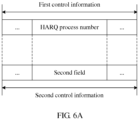
- a HARQ process number field in control information is redefined to indicate special retransmission, and specifically, to indicate data in a TB that is to be retransmitted.
- the first device When a first device transmits at least one TB for the first time, the first device sends first control information to a second device, where the first control information includes a HARQ process number field, and the HARQ process number field includes information about a HARQ process number used when the TB is sent for the first time.
- the first device When the first device retransmits the TB, the first device sends second control information to the second device, where the second control information includes a third field but does not include the HARQ process number field, and the third field includes information about a relationship between retransmitted data and the TB.
- a length of the third field is the same as a length of the HARQ process number field.
- a start location of the third field in the second control information is the same as a start location of the HARQ process number field in the first control information.
- a length of the second control information may be the same as a length of the first control information. Because the length of the second control information is the same as the length of the first control information, a quantity of blind detections performed by a receiving device for control information is not increased because the second control information is introduced, so as to effectively reduce complexity of the receiving device. As shown in FIG. 6A , the length of the first control information is the same as the length of the second control information, and the location and the length of the HARQ process number field are the same as the location and the length of the third field. This may also be understood as that the HARQ process number field in the first control information is redefined for the second control information. Optionally, other fields of the first control information and the second control information are all the same.
- the length of the HARQ process number field may be three bits or four bits, or may be another value, which specifically depends on a quantity of supported HARQ processes. This is not limited in this application.
- an MCS field and an RV field in control information may be redefined as a fourth field; in a case (2), an MCS field and a HARQ process number field may be redefined as a fourth field; in a case (3), a HARQ process number field and an RV field may be redefined as a fourth field; or in a case (4), an MCS field, an RV field, and a HARQ process number field in control information may be redefined as a fourth field.
- the fourth field in the figure is used to indicate data in the TB that is to be retransmitted.
- the fourth field includes two parts: P1 and P2.
- a sequence of P1 and P2 included in the fourth field is not limited in this application, in other words, P1 may be before P2, or P2 may be before P1.
- the fourth field includes three parts: P1, P2, and P3.
- a sequence of P1, P2, and P3 included in the fourth field is not limited in this application.
- the modulation and coding scheme field is adjacent to the HARQ process number field, and a new data indicator field is spaced between the HARQ process number field and the redundancy version field.
- FIG. 6B merely provides an example of relative locations of various fields in first control information.
- the various fields in the first control information may be further arranged in another manner.
- a sequence of the various fields is sequentially: a modulation and coding scheme field, a HARQ process number field, a new data indicator field, and a redundancy version field.
- the first control information includes the foregoing various fields, and the first control information may further include other fields that are not shown in the figure.
- a plurality of fields are redefined, so that more bits can be used to indicate data in the TB that is to be retransmitted.
- the control information can indicate a finer granularity, invalid retransmission can be reduced, and retransmission efficiency can be improved.
- the fourth field indicates data in the TB that is to be retransmitted, directly refer to Embodiment 1 and Examples 2 and 3 described above. Details are not described herein again.
- FIG. 7 is a schematic diagram of another data transmission method according to a further competitive example.
- data in a TB that is to be transmitted is implicitly indicated by using a time-frequency resource used for retransmission.
- the first device When a first device transmits at least one TB for the first time, the first device sends the TB to a second device on a second time-frequency resource, where the second time-frequency resource includes at least two third time-frequency resources, and the third time-frequency resource includes at least one time domain symbol, or at least one mini-slot, or at least one slot, or at least one RB.
- the second time-frequency resource includes P third time-frequency resources, and P is an integer greater than 2.
- the first device When the first device retransmits the TB, the first device sends a part of data in the TB to the second device on one third time-frequency resource in the second time-frequency resource, where a location or an index value of the third time-frequency resource implicitly indicates data in the TB that is to be retransmitted.
- the second time-frequency resource and the third time-frequency resource may be indicated in a resource block assignment (resource block assignment, RA) field, or may be indicated in another field. This is not limited in this application.
- the third time-frequency resource includes the at least one RB is used to further describe this example.
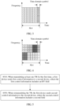
- FIG. 8 it is assumed that 16 RBs are used when the TB is transmitted for the first time, indexes are respectively ⁇ x1, x2, ..., x16 ⁇ in descending order, and the 16 RBs constitute the second time-frequency resource.
- the second time-frequency resource is divided into four third time-frequency resources that are contiguous in frequency domain, in a contiguous resource allocation manner.
- indexes of RBs allocated for retransmission include only indexes in S2 and S4, it indicates that data in the second CB and the fourth CB, or data in the second CB group and the fourth CB group, or data on the second third time-frequency resource and the fourth third time-frequency resource is to be retransmitted.
- indexes are respectively ⁇ x1, x2, ..., x16 ⁇ in descending order, and the 16 RBs constitute the second time-frequency resource.
- indexes of RBs allocated for retransmission include only an index in S1, it indicates that data in the first CB or the first CB group or data on the first third time-frequency resource is to be retransmitted. If indexes of RBs allocated for retransmission include only indexes in S2 and S4, it indicates that data in the second CB and the fourth CB, or data in the second CB group and the fourth CB group, or data on the second third time-frequency resource and the fourth third time-frequency resource is to be retransmitted.
- data in the TB that is to be retransmitted may be further implicitly indicated by using an index number of an RB allocated for retransmission.
- a modulo operation may be performed, by using an index number of an RB, on a quantity of CBs used during initial transmission, to indicate a CB to which currently retransmitted data belongs; or a modulo operation may be performed, by using an index number of an RB, on a quantity of CB groups used during initial transmission, to indicate a CB group to which currently retransmitted data belongs; or a modulo operation may be performed, by using an index number of an RB, on a quantity of time-frequency resources used during initial transmission, to indicate a time-frequency resource to which currently retransmitted data belongs.
- the index number of the RB may be a smallest index number of an RB in a time-frequency resource used during retransmission, or may be a largest or smallest index number of an RB in a time-frequency resource used during retransmission, or all index numbers in a time-frequency resource used during retransmission that satisfy one of the foregoing conditions.
- a smallest value of an index number of an RB in a time-frequency resource allocated for retransmission may satisfy 4*x+1, where x is an integer; or if the third CB group needs to be retransmitted, a smallest value of an index number of an RB in a time-frequency resource allocated for retransmission satisfies 4*x+3.
- the third time-frequency resource and how to indicate data in the TB that is to be retransmitted are described above by using an example from a dimension of frequency domain, and an example is used below for description from a dimension of time domain.
- the third time-frequency resource may include at least one time domain symbol at a granularity of a time domain symbol, or may include at least one mini-slot at a granularity of a mini-slot, or may include at least one slot at a granularity of a slot, or may be based on a granularity of another time domain unit. This is not limited in this application.
- a time-frequency resource of one slot is used when the TB is transmitted for the first time, and the slot includes a plurality of mini-slots. If a time-frequency resource of one mini-slot is used during retransmission, a number of the mini-slot in the slot may be used to indicate currently retransmitted data in the TB. For another example, slot aggregation transmission of a plurality of slots is used when the TB is transmitted for the first time. If a time-frequency resource of one or more slots is used during retransmission, a number of the slot used during the retransmission in the slot aggregation transmission may be used to indicate currently retransmitted data in the TB.
- time-frequency resources of four slots are allocated for initial transmission of data.
- the data that is transmitted for the first time is divided into four CB groups. If the first CB group needs to be retransmitted, only the first slot in the four slots needs to be allocated during retransmission. If the third CB group needs to be retransmitted, only the third slot in the four slots needs to be allocated during retransmission.
- one slot is used as a scheduling period, and a time-frequency resource of one slot is allocated for initial transmission of data.
- the data that is transmitted for the first time is divided into four CB groups, and one slot includes four mini-slots.
- a location of the time-frequency resource allocated for retransmission is the same as a location of the time-frequency resource that is affected by puncturing of the URLLC service data.
- a bandwidth of the upper half part of the second mini-slot in the slot is also allocated for retransmission.
- the third time-frequency resource herein may also be the first time-frequency resource in FIG. 3 or FIG. 4
- the corresponding second time-frequency resource is a time-frequency resource of one slot in FIG. 3 and FIG. 4 .
- a specific bit in an existing field in control information may be used for indication.
- the MSB or the LSB of the MCS field is used for indication.
- higher layer signaling is used to indicate whether special retransmission is supported, to indicate that physical layer control information used during special retransmission is which solution in the embodiments and examples described above, for example, to indicate whether the solution of reusing the MCS field in Embodiment 1 or the solution of reusing the MCS field and the RV field in Embodiment 4 is used.
- the higher layer signaling may be radio resource control (radio resource control, RRC) layer signaling or medium access control (medium access control, MAC) layer signaling.
- a new field is added to physical layer control information, to indicate whether retransmission corresponding to the control information is normal retransmission or special retransmission, or to indicate whether there is an MCS field or the like, or to indicate whether an MCS field or the like is parsed through reusing.
- the field may further indicate whether special retransmission is retransmission of data in a CB that encounters a decoding error or data in a CB group that encounters a decoding error or retransmission of data on a time-frequency resource that is affected by puncturing.
- the physical layer control information herein may be DCI or UCI.
- the newly added field may be 1-bit, to indicate whether retransmission of all data corresponding to the control information is normal retransmission or special retransmission.
- the newly added field may alternatively be 2-bit, to indicate retransmission of all data corresponding to the control information is normal retransmission, or retransmission of data in some CBs or some CB groups, o retransmission of data on a time-frequency resource that is affected by puncturing.
- the newly added field may alternatively be multi-bit. Each bit or every two bits are used to indicate whether transmission of corresponding data in one CB or one CB group or corresponding data on one time-frequency resource is normal retransmission or special retransmission.
- the field may further indicate whether the retransmission is supplementary transmission in special retransmission.
- different formats of control information are used to distinguish between different retransmission types. For example, for normal retransmission, format 1 is used, and for special retransmission, format 2 is used.
- a receiving device may know a currently used retransmission mode by blindly detecting a format of control information.
- a cyclic redundancy check (cyclic redundancy check, CRC) bit sequence of control information is scrambled by using different sequences, to distinguish between retransmission types.
- a CRC bit sequence generated by control information for normal retransmission is scrambled by using a sequence 1
- a CRC bit sequence generated by control information for special retransmission is scrambled by using a sequence 2.
- the receiving device may know a current retransmission type by detecting a scrambling sequence used for a CRC of control information.
- the sequence 1 and the sequence 2 herein may be radio network temporary identifiers (radio network temporary identifier, RNTI).
- a location of control information is used to distinguish between retransmission types.
- the retransmission types may be distinguished between each other based on a time-frequency resource on which the control information is located.
- the time-frequency resource on which the control information is located is an RB set 1 or a subband 1, it indicates normal retransmission, and otherwise, it indicates special retransmission.
- the time-frequency resource on which the control information is located is an RB set 2 or a subband 2, it indicates special retransmission, and otherwise, it indicates normal retransmission.
- the retransmission types may alternatively be distinguished between each other based on search space in which the control information is located.
- control information When the control information is located in UE-specific search space, it indicates normal retransmission, and otherwise, it indicates special retransmission. Alternatively, when the control information is located in common search space, it indicates special retransmission, and otherwise, it indicates normal retransmission. Alternatively, when the control information is located in UE-specific search space, it indicates special retransmission, and otherwise, it indicates normal retransmission.
- a retransmission type is implicitly indicated by using a retransmission occasion. For example, before the receiving device feeds back an ACK/a NACK, the receiving device blindly detects control information by using a format of control information for special retransmission, and parses the control information based on the format of control information for special retransmission. After the receiving device feeds back the ACK/NACK, the receiving device blindly detects control information by using a format of control information for normal retransmission, and parses the control information based on the format of control information for normal retransmission.
- a combination of a plurality of fields is used to distinguish between retransmission types. For example, if an NDI indicates new transmission, and an RV is a non-zero value, parsing is performed based on a format of control information for special retransmission.
- a combination of at least two of the foregoing methods is used. For example, before the receiving device feeds back an ACK/a NACK, the receiving device blindly detects and parses control information based on a format of control information for special retransmission. After the receiving device feeds back the ACK/NACK, if an NDI indicates new transmission and an RV is a non-zero value, the receiving device parses the control information based on the format of control information for special retransmission, and otherwise, the receiving device parses the control information based on a format of control information for normal retransmission.
- a TB including four CB groups is transmitted is used below to describe processes of normal retransmission and special retransmission.
- a time-frequency resource for the third CB group in the four CB groups used during initial transmission is preempted
- a retransmission type is set to special retransmission
- retransmission of the third CB group is indicated.
- the receiving device clears buffer data of the third CB group that is received during the initial transmission, does not participate in HARQ combination of retransmitted data, and places data received during the retransmission into a buffer of the third CB group for decoding.
- the receiving device After receiving the retransmitted control information, the receiving device performs HARQ combination on the data of the third CB group that is received during the retransmission and the data of the third CB group that is received during the initial transmission, and then performs decoding.
- Specific data that is to be retransmitted needs to be indicated in control information for special retransmission in the embodiments and examples described above, and there is another possible implementation method in which data that is to be retransmitted is determined with reference to another indication.
- a sending device may indicate, to a receiving device with reference to a puncturing indication, a time-frequency resource, for the eMBB service data, to which data that is punctured belongs, so that during retransmission, the sending device can retransmit only data on the time-frequency resource that is affected by puncturing.
- the retransmission is special retransmission, and there are the following three different design methods for control information for special retransmission:
- the puncturing indication may be an indication on a punctured symbol or mini-slot, or may be an indication on the last symbol or mini-slot for current eMBB service data transmission. For example, assuming that the current eMBB service data transmission occupies one slot, an indication may be performed on the last symbol of the slot.
- a puncturing indication manner is not limited in this application.
- the puncturing indication herein is also referred to as indication information for auxiliary reception that is sent by the sending device to the receiving device.
- the sending device may send the indication information for auxiliary reception to the receiving device.
- the indication information for auxiliary reception is used to notify the receiving device of an area affected by the preemption or the interference, to assist the receiving device in receiving and decoding data.
- the receiving device may discard data in a corresponding affected area, and the data in the area does not participate in decoding and HARQ combination, so as to improve a decoding success rate and improve data transmission efficiency.
- the sending device may retransmit only the data in the affected area with reference to the indication information for auxiliary reception.
- meanings of the puncturing indication and the indication information for auxiliary reception are the same, and the two can be replaced with each other.
- the receiving device may determine currently retransmitted data with reference to the content of the indication information for auxiliary reception according to the following method:
- the sending device when the sending device performs special retransmission after receiving an ACK/a NACK fed back by the receiving device, the sending device may no longer retransmit data in a CB or a CB group for which an ACK is fed back or data on a time-frequency resource for which an ACK is fed back.
- a range of retransmitted data in special retransmission is limited by a quantity of bits used for the indication in control information.
- a quantity of bits used for the indication in control information For example, when an MCS field is reused in Embodiment 1, if a variable modulation scheme is supported, only two bits may be used to indicate the range of the retransmitted data.
- a new field may be introduced to the control information or a quantity of bits in a reused field may be increased, to support a larger indication range. For example, six bits may be simultaneously used to support retransmission indications of six CB groups.
- the method embodiment is mainly described from a perspective of the sending device in the embodiments and examples described above. It may be understood that the method may also be applied to the receiving device. With reference to the method of the sending device, correspondingly, the receiving device receives related information, and then may perform processing according to the method corresponding to the sending device. Details are not described herein.
- an NDI 0 in control information indicates initial transmission, and an NDI 1 indicates retransmission; or non-reversal of an NDI indicates retransmission, and reversal of an NDI indicates new transmission.
- Reversal herein means that an NDI changes from 0 to 1 or changes from 1 to 0.
- a same NDI may be set for all CB groups, or an NDI may be set for each CB group. In this case, new transmission or retransmission may be independently indicated for each CB group.
- An NDI field may be used to indicate whether current transmission of data in a CB or a CBG or data on a time-frequency resource is new transmission, normal retransmission, or special retransmission, and the NDI may further indicate whether the current special retransmission is partial retransmission or supplementary transmission.
- a name of the NDI herein is merely an example, and the name of the NDI is not limited in this application. These assumptions are merely for ease of description, and can be appropriately adjusted during actual application.
- a multi-bit feedback described below is introduced by the receiving device to indicate, to the sending device, a part of currently transmitted data that encounters a decoding error.
- one TB includes four CB groups
- the receiving device may feed back 4-bit ACK/NACK information such as 1010 to the sending device.
- a plurality of bits are fed back when needed. If one TB includes only one CB group, only one bit may be fed back.
- a quantity of bits that are fed back may be determined by using a plurality of methods. A method for determining a quantity of bits that are fed back is not limited in this application.
- a location for sending indication information for auxiliary reception is not limited in this application.
- the indication information for auxiliary reception may be carried at the end of a current time unit, or may be carried in DCI of a next time unit, or may be carried in DCI of a time unit for retransmission or special retransmission in a current process.
- the sending device may send the indication information for auxiliary reception before receiving an ACK/a NACK, or may send the indication information for auxiliary reception after receiving an ACK/a NACK.
- All CBs that are affected by preemption may be determined based on a time-frequency resource indicated by the indication information for auxiliary reception, to serve as one CB group for supplementary transmission, or the indication information for auxiliary reception may directly indicate numbers or bitmaps of all preempted CB groups.
- Solution 1 A multi-bit feedback is combined with a retransmission indication. After receiving data in the TB, the receiving device feeds back a binary sequence 1010 based on a decoding result, to indicate that the first and the third CB groups encounter a decoding error. After receiving the feedback, the sending device may send control information by using the indication method for special retransmission in Embodiment 1 to Embodiment 8 described above, or may indicate retransmission of the first and the third CB groups in a manner that is not limited to the manner in this example of this application. After receiving the control information for retransmission and the data, the receiving device performs data processing.
- the NDI indicates retransmission of both the first CB group and the third CB group, so that HARQ combination with previously transmitted data is performed.
- the NDI indicates new transmission of both the first CB group and the third CB group.
- corresponding data in the first CB group and data in the third CB group may be transmitted, or data in the first CB group and data that is in the third CB group and that is corresponding to a location of a preempted resource may be transmitted, so that previous corresponding buffer data is erased, and corresponding buffer data is updated with received data.
- the third bit in an NDI field of four bits is used to indicate new transmission of the third CB group, and another CB group is not retransmitted.
- corresponding data in the third CB group may be data in the complete third CB group, or may be data that is in the third CB group and that is corresponding to a location of a preempted resource.
- the first bit in the NDI field is used to indicate retransmission of the first CB group.
- a receive end After receiving the retransmitted control information and data, a receive end performs data processing, for example, performs HARQ combination on initially transmitted data and retransmitted data in the first CB group, erases previous corresponding buffer data in the third CB group, updates the corresponding buffer with newly received data in the third CB group, and performs decoding and feeds back a decoding result.
- Solution 2 Indication information for auxiliary reception is combined with a multi-bit feedback and a retransmission indication.
- the sending device may send indication information for auxiliary reception, which is, for example, 1-bit, to indicate whether resource preemption occurs in current data transmission.
- the receiving device determines, according to whether the indication information for auxiliary reception is received, a quantity of bits that are fed back.
- the quantity of bits that are fed back by the receiving device may be determined according to the indication information for auxiliary reception.
- the indication information for auxiliary reception is received, a plurality of bits are fed back, in other words, four bits 1010 (indicating a NACK for the first and the third CB groups) are fed back, and otherwise, a 1-bit NACK is fed back optionally.
- the quantity of bits that are fed back by the receiving device may be determined without using the indication information for auxiliary reception.
- a multi-bit feedback may be performed according to a normal procedure.
- the sending device may send control information by using the indication method for the retransmission in the embodiments and examples described above, or may indicate retransmission of the first and the third CB groups in a manner that is not limited to the manner in this example.
- the receiving device After receiving the control information for retransmission and the data, the receiving device performs data processing.
- An example is as follows:
- the NDI indicates retransmission of the first CB group and the third CB group, so that HARQ combination with previously transmitted corresponding data is performed.
- the NDI indicates new transmission of the first CB group and the third CB group.
- corresponding data in the first CB group and data in the third CB group may be transmitted, or data in the first CB group and data that is in the third CB group and that is corresponding to a location of a preempted resource may be transmitted, so that previous corresponding buffer data is erased, and corresponding buffer data is updated with newly received data, and then decoding is performed and a decoding result is fed back.
- Solution 3 Indication information for auxiliary reception is combined with a multi-bit feedback and a retransmission indication.
- the sending device may send indication information for auxiliary reception, which is, for example, 1-bit, to indicate whether resource preemption occurs in current data transmission.
- the receiving device determines, according to whether the indication information for auxiliary reception is received, a quantity of bits that are fed back. Optionally, the quantity of bits that are fed back by the receiving device may be determined according to the indication information for auxiliary reception.
- the indication information for auxiliary reception is received, a plurality of bits are fed back, in other words, four bits 1010 (indicating a NACK for the first and the third CB groups) are fed back, and otherwise, a 1-bit NACK is fed back optionally.
- the quantity of bits that are fed back by the receiving device may be determined without using the indication information for auxiliary reception.
- a multi-bit feedback may be performed according to a normal procedure.
- the sending device may send control information by using the indication method for special retransmission in the embodiments and examples described above, or may indicate retransmission of the first and the third CB groups in a manner that is not limited to the manner in this example.
- the NDI is used to indicate new transmission of the third CB group.
- corresponding data in the third CB group may be data in the complete third CB group, or may be data that is in the third CB group and that is corresponding to a location of a preempted resource.
- the NDI is used to indicate retransmission of the first CB group.
- a receive end After receiving the retransmitted control information and data, a receive end performs data processing, for example, performs HARQ combination on initially transmitted data and retransmitted data in the first CB group, erases previous corresponding buffer data in the third CB group, updates the corresponding buffer with newly received data in the third CB group, and performs decoding and feeds back a decoding result.
- data processing for example, performs HARQ combination on initially transmitted data and retransmitted data in the first CB group, erases previous corresponding buffer data in the third CB group, updates the corresponding buffer with newly received data in the third CB group, and performs decoding and feeds back a decoding result.
- some other independent fields may be further introduced into each CB group. For example, each CB group may have an independent RV field.
- Solution 4 Indication information for auxiliary reception is combined with a multi-bit feedback and a retransmission indication.
- the sending device may send indication information for auxiliary reception, which is, for example, 1-bit, to indicate whether resource preemption occurs in current data transmission.
- the receiving device determines, according to whether the indication information for auxiliary reception is received, a quantity of bits that are fed back.
- the quantity of bits that are fed back by the receiving device may be determined according to the indication information for auxiliary reception.
- the indication information for auxiliary reception is received, a plurality of bits are fed back, in other words, four bits 1010 (indicating a NACK for the first and the third CB groups) are fed back, and otherwise, a 1-bit NACK is fed back optionally.
- the quantity of bits that are fed back by the receiving device may be determined without using the indication information for auxiliary reception.
- a multi-bit feedback may be performed according to a normal procedure.
- the sending device may send control information by using the indication method for special retransmission in the embodiments and examples described above, or may indicate retransmission of the third CB group in a manner that is not limited to the manner in the present invention.
- the NDI is used to indicate new transmission of the third CB group.
- corresponding data in the third CB group may be data in the complete third CB group, or may be data that is in the third CB group and that is corresponding to a location of a preempted resource.
- the receiving device After receiving the retransmitted control information and data of the third CB group, the receiving device performs data processing, for example, erases previous corresponding buffer data in the third CB group, updates the corresponding buffer with newly received data in the third CB group, and performs decoding and feeds back a decoding result.
- the first CB group is individually retransmitted.
- the NDI is used to indicate retransmission of the first CB group, and a retransmission indication method is the same as that for the third CB group.
- the receiving device After receiving the retransmitted control information and data of the first CB group, the receiving device performs data processing, for example, performs HARQ combination with the previously received data of the first CB group, and then performs decoding and feeds back a decoding result.
- Solution 5 A 1-bit feedback is combined with a special retransmission indication. After receiving data in a TB, the receiving device feeds back a 1-bit NACK if a CB encounters a decoding error. The sending device determines retransmitted data and control information based on a feedback result and whether resource preemption occurs in a previous transmission process. After receiving the feedback, the sending device may send control information by using the indication method for special retransmission in the embodiments and examples described above, to indicate retransmission of the first and the third CB groups, and indicate retransmission of the third CB group that is performed because of impact of puncturing, and retransmission of the first CB group that is performed because of no impact of puncturing.
- a receive end After receiving the retransmitted control information and data, a receive end performs data processing, for example, performs HARQ combination on initially transmitted data and retransmitted data in the first CB group, erases previous buffer data in the third CB group that is affected by the puncturing, and feeds back a decoding result based on a processing result.
- data processing for example, performs HARQ combination on initially transmitted data and retransmitted data in the first CB group, erases previous buffer data in the third CB group that is affected by the puncturing, and feeds back a decoding result based on a processing result.
- other independent fields may be further introduced into each CB group.
- each CB group may have an independent RV field.
- Solution 6 A 1-bit feedback is combined with a retransmission indication. After receiving data in a TB, the receiving device feeds back a 1-bit NACK if a CB encounters a decoding error. The sending device determines retransmitted data and control information based on a feedback result and whether resource preemption occurs in a previous transmission process. After receiving the feedback, the sending device may send control information by using the indication method for special retransmission in the embodiments and examples described above, or may indicate retransmission of the third CB group in a manner that is not limited to the manner in the embodiments of this application. In addition, optionally, the NDI is used to indicate new transmission of the third CB group.
- corresponding data in the third CB group may be data in the complete third CB group, or may be data that is in the third CB group and that is corresponding to a location of a preempted resource.
- the receiving device After receiving the retransmitted control information and data of the third CB group, the receiving device performs data processing, for example, erases previous corresponding buffer data in the third CB group, updates the corresponding buffer with newly received data in the third CB group, and performs decoding and feeds back a decoding result.
- the third CB group is retransmitted, the first CB group is individually retransmitted.
- the NDI is used to indicate retransmission of the first CB group, and a retransmission indication method is the same as that for the third CB group.
- the receiving device After receiving the retransmitted control information and data of the first CB group, the receiving device performs data processing, for example, performs HARQ combination with the previously received data of the first CB group, and then performs decoding and feeds back a decoding result.
- Solution 7 Indication information for auxiliary reception is combined with a 1-bit feedback and a retransmission indication.
- the sending device may send indication information for auxiliary reception, which is, for example, N-bit, to indicate a number or a bitmap of a preempted CB group, or to indicate location information of a preempted time-frequency resource.
- the receiving device erases, according to the indication information for auxiliary reception, previous buffer data that is affected by puncturing. The erasing operation may be performed before channel decoding and a feedback, or may be performed after channel decoding and a feedback. If the decoding fails, the receiving device feeds back a 1-bit NACK.
- the sending device may send control information by using the indication method for special retransmission in the embodiments and examples described above, or may indicate retransmission of the third CB group in a manner that is not limited to the manner in this example.
- the NDI is used to indicate retransmission of the third CB group.
- corresponding data in the third CB group may be data in the complete third CB group, or may be data that is in the third CB group and that is corresponding to a location of a preempted resource.
- the receiving device After receiving the retransmitted control information and data of the third CB group, the receiving device performs data processing, for example, performs HARQ combination with the previously received data of the third CB group, and then performs decoding and feeds back a decoding result.
- the third CB group After the third CB group is retransmitted, the first CB group is individually retransmitted.
- the NDI is used to indicate retransmission of the first CB group, and a retransmission indication method is the same as that for the third CB group.
- the receiving device After receiving the retransmitted control information and data of the first CB group, the receiving device performs data processing, for example, performs HARQ combination with the previously received data of the first CB group, and then performs decoding and feeds back a decoding result.
- Solution 8 Indication information for auxiliary reception is combined with a multi-bit feedback and a retransmission indication.
- the sending device may send indication information for auxiliary reception, which is, for example, N-bit, to indicate a number or a bitmap of a preempted CB group, or to indicate location information of a preempted time-frequency resource.
- the receiving device erases, according to the indication information for auxiliary reception, previous buffer data that is affected by puncturing. The erasing operation may be performed before channel decoding and a feedback, or may be performed after channel decoding and a feedback.
- a quantity of bits that are fed back by the receiving device may be determined according to the indication information for auxiliary reception.
- the indication information for auxiliary reception is received, a plurality of bits are fed back, in other words, four bits 1010 (indicating a NACK for the first and the third CB groups) are fed back, and otherwise, a 1-bit NACK is fed back optionally.
- the quantity of bits that are fed back by the receiving device may be determined without using the indication information for auxiliary reception.
- a multi-bit feedback may be performed according to a normal procedure.
- the sending device may send control information by using the indication method for special retransmission in the embodiments and examples described above, or may indicate retransmission of the first CB group and the third CB group in a manner that is not limited to the manner in this example.
- the NDI is used to indicate retransmission of the first CB group and the third CB group.
- corresponding data in the first CB group may be retransmitted data
- data in the third CB group may be data in the complete third CB group, or may be data that is in the third CB group and that is corresponding to a location of a preempted resource.
- the receiving device After receiving the retransmitted control information and data of the first CB group and the third CB group, the receiving device performs data processing, for example, performs HARQ combination with the previously received data of the first CB group and the third CB group, and then performs decoding and feeds back a decoding result.
- the data transmission method provided in the embodiments of this application is described separately from perspectives of the sending device, the receiving device, and interaction between the sending device and the receiving device.
- various devices such as the sending device and the receiving device include corresponding hardware structures and/or software modules for performing the functions.
- a person of ordinary skill in the art should easily be aware that, in combination with units and method steps in the examples described in the embodiments disclosed in this specification, this application can be implemented by hardware or a combination of hardware and computer software. Whether a function is performed by hardware or hardware driven by computer software depends on particular applications and design constraints of the technical solutions. A person skilled in the art may use different methods to implement the described functions for each particular application, but it should not be considered that the implementation goes beyond the scope of this application.
- FIG. 10 and FIG. 11 are schematic structural diagrams of two possible communications apparatuses according to embodiments of this application.
- the communications apparatus implements functions of the sending device in the method embodiments described above, and therefore can also implement beneficial effects of the method embodiments.
- the communications apparatus may be the UE 130 or the UE 140 or the base station 120 shown in FIG. 1 , or may be another device on a sending side that performs wireless communication.
- a communications apparatus 1000 includes a processing unit 1010 and a sending unit 1020.
- the processing unit 1010 is configured to generate first control information, where the first control information is control information that is sent by the communications apparatus to a second device when the communications apparatus transmits at least one transport block TB for the first time, the first control information includes a modulation and coding scheme MCS field, and the MCS field includes at least one of information about a modulation scheme used when the TB is sent and information about a transport block size TBS.
- first control information is control information that is sent by the communications apparatus to a second device when the communications apparatus transmits at least one transport block TB for the first time
- the first control information includes a modulation and coding scheme MCS field
- the MCS field includes at least one of information about a modulation scheme used when the TB is sent and information about a transport block size TBS.
- the sending unit 1020 is configured to send the first control information to the second device.
- the processing unit 1010 is further configured to generate second control information, where the second control information is control information that is sent by the communications apparatus to the second device when the communications apparatus retransmits the TB, the second control information includes a first field, the first field includes information about a relationship between retransmitted data and the TB, and the second control information does not include the MCS field.
- the second control information is control information that is sent by the communications apparatus to the second device when the communications apparatus retransmits the TB
- the second control information includes a first field
- the first field includes information about a relationship between retransmitted data and the TB
- the second control information does not include the MCS field.
- the sending unit 1020 is further configured to send the second control information to the second device.
- a length of the first field is the same as a length of the MCS field.
- a start location of the first field in the second control information is the same as a start location of the MCS field in the first control information.
- a communications apparatus 1100 includes a processor 1110, a transceiver 1120, and a memory 1130.
- the memory 1130 may be configured to store code for execution by the processor 1110.
- the components in the communications apparatus 1100 communicate with each other through an internal connection path, for example, transmit a control and/or data signal by using a bus.
- the processor 1110 is configured to generate first control information, where the first control information is control information that is sent by the communications apparatus to a second device when the communications apparatus transmits at least one transport block TB for the first time, the first control information includes a modulation and coding scheme MCS field, and the MCS field includes at least one of information about a modulation scheme used when the TB is sent and information about a transport block size TBS.
- first control information is control information that is sent by the communications apparatus to a second device when the communications apparatus transmits at least one transport block TB for the first time
- the first control information includes a modulation and coding scheme MCS field
- the MCS field includes at least one of information about a modulation scheme used when the TB is sent and information about a transport block size TBS.
- the processor 1110 is further configured to generate second control information, where the second control information is control information that is sent by the communications apparatus to the second device when the communications apparatus retransmits the TB, the second control information includes a first field, the first field includes information about a relationship between retransmitted data and the TB, and the second control information does not include the MCS field.
- the second control information is control information that is sent by the communications apparatus to the second device when the communications apparatus retransmits the TB
- the second control information includes a first field
- the first field includes information about a relationship between retransmitted data and the TB
- the second control information does not include the MCS field.
- the transceiver 1120 is further configured to send the second control information to the second device.
- a length of the first field is the same as a length of the MCS field.
- a start location of the first field in the second control information is the same as a start location of the MCS field in the first control information.
- processing unit 1010 the processor 1110, the sending unit 1020, and the transceiver 1120, directly refer to the foregoing method embodiments. Details are not described herein again.
- FIG. 12 and FIG. 13 are schematic structural diagrams of two other possible communications apparatuses according to embodiments of this application.
- the communications apparatus implements functions of the receiving device in the method embodiments described above, and therefore can also implement beneficial effects of the method embodiments.
- the communications apparatus may be the UE 130 or the UE 140 or the base station 120 shown in FIG. 1 , or may be another device on a receiving side that performs wireless communication
- a communications apparatus 1200 includes a receiving unit 1210 and a processing unit 1220.
- the receiving unit 1210 is configured to receive first control information, where the first control information is control information from a first device when the first device transmits at least one transport block TB to the communication device for the first time, the first control information includes a modulation and coding scheme MCS field, and the MCS field includes at least one of information about a modulation scheme used when the TB is sent and information about a transport block size TBS.
- first control information is control information from a first device when the first device transmits at least one transport block TB to the communication device for the first time
- the first control information includes a modulation and coding scheme MCS field
- the MCS field includes at least one of information about a modulation scheme used when the TB is sent and information about a transport block size TBS.
- the processing unit 1220 is configured to parse the first control information.
- the receiving unit 1210 is further configured to receive second control information, where the second control information is control information from the first device when the first device retransmits the TB to the communications apparatus, the second control information includes a first field, the first field includes information about a relationship between retransmitted data and the TB, and the second control information does not include the MCS field.
- the second control information is control information from the first device when the first device retransmits the TB to the communications apparatus
- the second control information includes a first field
- the first field includes information about a relationship between retransmitted data and the TB
- the second control information does not include the MCS field.
- the processing unit 1220 is further configured to parse the second control information.
- a length of the first field is the same as a length of the MCS field.
- a start location of the first field in the second control information is the same as a start location of the MCS field in the first control information.
- a communications apparatus 1300 includes a processor 1320, a transceiver 1310, and a memory 1330.
- the memory 1330 may be configured to store code for execution by the processor 1320.
- the components in the communications apparatus 1300 communicate with each other through an internal connection path, for example, transmit a control and/or data signal by using a bus.
- the transceiver 1310 is configured to receive first control information, where the first control information is control information from a first device when the first device transmits at least one transport block TB to the communications apparatus for the first time, the first control information includes a modulation and coding scheme MCS field, and the MCS field includes at least one of information about a modulation scheme used when the TB is sent and information about a transport block size TBS.
- the processor 1320 is configured to parse the first control information.
- the transceiver 1310 is further configured to receive second control information, where the second control information is control information from the first device when the first device retransmits the TB to the communications apparatus, the second control information includes a first field, the first field includes information about a relationship between retransmitted data and the TB, and the second control information does not include the MCS field.
- the processor 1320 is further configured to parse the second control information.
- a length of the first field is the same as a length of the MCS field.
- a start location of the first field in the second control information is the same as a start location of the MCS field in the first control information.
- FIG. 11 and FIG. 13 each merely show a design of the communications apparatus.
- the communications apparatus may include any quantity of receivers and processors, and all communications apparatuses that can implement the embodiments of this application shall fall within the protection scope of this application.
- FIG. 10 to FIG. 13 are obtained by referring to the method embodiment in Embodiment 1. It may be understood that another apparatus embodiment of this application may be directly obtained by referring to another method embodiment of this application, and details are not described herein again.
- the processor in the embodiments of this application may be a central processing unit (Central Processing Unit, CPU), may be another general-purpose processor, a digital signal processor (Digital Signal Processor, DSP), an application-specific integrated circuit (Application-Specific Integrated Circuit, ASIC), a field programmable gate array (Field-Programmable Gate Array, FPGA) or another programmable logic device, a transistor logic device, a hardware component, or a combination thereof.
- the general-purpose processor may be a microprocessor, or may be any regular processor.
- the method steps in the embodiments of this application may be implemented by hardware or may be implemented by the processor executing a software instruction.
- the software instruction may include a corresponding software module.
- the software module may be stored in a random access memory (Random Access Memory, RAM), a flash memory, a read-only memory (Read-Only Memory, ROM), a programmable read only memory (Programmable ROM, PROM), an erasable programmable read-only memory (Erasable PROM, EPROM), an electrically erasable programmable read only memory (Electrically EPROM, EEPROM), a register, a hard disk, a removable hard disk, a CD-ROM, or any other form of storage medium well-known in the art.
- RAM Random Access Memory
- ROM read-only memory
- PROM programmable read only memory
- Erasable PROM Erasable PROM
- EPROM electrically erasable programmable read only memory
- EEPROM Electrically erasable programm
- the storage medium is coupled to the processor, so that the processor can read information from the storage medium or write information into the storage medium.
- the storage medium may be a component of the processor.
- the processor and the storage medium may be located in the ASIC.
- the ASIC may be located in a sending device or a receiving device.
- the processor and the storage medium may exist in a sending device or a receiving device as discrete components.
- All or some of the foregoing embodiments may be implemented by software, hardware, firmware, or any combination thereof.
- the embodiments may be implemented completely or partially in a form of a computer program product.
- the computer program product includes one or more computer instructions.
- the computer may be a general-purpose computer, a dedicated computer, a computer network, or other programmable apparatuses.
- the computer instruction may be stored in a computer readable storage medium, or may be transmitted through the computer readable storage medium.
- the computer instructions may be transmitted from a website, a computer, a server, or a data center to another website, computer, server, or data center in a wired (for example, through a coaxial cable, an optical fiber, or a digital subscriber line (DSL)) or wireless (for example, through infrared, radio, or microwave) manner.
- the computer readable storage medium may be any usable medium accessible by a computer, or a data storage device, such as a server or a data center, integrating one or more usable media.
- the usable medium may be a magnetic medium (for example, a floppy disk, a hard disk, or a magnetic tape), an optical medium (for example, a DVD), a semiconductor medium (for example, a solid state disk (Solid State Disk, SSD)), or the like.
- a magnetic medium for example, a floppy disk, a hard disk, or a magnetic tape
- an optical medium for example, a DVD
- a semiconductor medium for example, a solid state disk (Solid State Disk, SSD)
- sequence numbers of the foregoing processes do not mean execution sequences in the embodiments of this application, and should not be construed as any limitation on the implementation processes of the embodiments of this application.
- the execution sequences of the processes should be determined according to functions and internal logic of the processes.
Landscapes
- Engineering & Computer Science (AREA)
- Signal Processing (AREA)
- Computer Networks & Wireless Communication (AREA)
- Quality & Reliability (AREA)
- Mobile Radio Communication Systems (AREA)
- Detection And Prevention Of Errors In Transmission (AREA)
Claims (9)
- Datenübertragungsverfahren, wobei das Verfahren Folgendes umfasst:wenn eine erste Vorrichtung zum ersten Mal mindestens einen Transportblock, TB, überträgt, Senden (S210), durch die erste Vorrichtung, erster Steuerinformationen an eine zweite Vorrichtung, wobei die ersten Steuerinformationen ein Modulations- und Codierungsschema(MSC)-Feld umfassen und das MCS-Feld Informationen über ein Modulationsschema, das beim Senden des TB verwendet wird, und Informationen über eine Transportblockgröße, TBS, umfasst; undwenn die erste Vorrichtung den TB erneut überträgt, Senden (S220), durch die erste Vorrichtung, zweiter Steuerinformationen an die zweite Vorrichtung, wobei die zweiten Steuerinformationen ein erstes Feld umfassen, aber nicht das MCS-Feld und die Informationen über die TBS umfassen, undwobei eine Länge des ersten Felds gleich einer Länge des MCS-Felds ist und eine Startposition des ersten Felds in den zweiten Steuerinformationen gleich einer Startposition des MCS-Felds in den ersten Steuerinformationen ist,wobei eine Länge der zweiten Steuerinformationen kleiner oder gleich einer Länge der ersten Steuerinformationen ist,wobei in dem ersten Feld eine Modulationsreihenfolge und ein Codeblockgruppen(CBG)-Index gemeinsam codiert sind,wobei der CBG-Index eine Beziehung zwischen erneut übertragenen Daten und dem TB anzeigt, undwobei die Beziehung zwischen den erneut übertragenen Daten und dem TB Folgendes umfasst:
die erneut übertragenen Daten sind mindestens eine Codeblock(CB)-Gruppe in dem TB und die CB-Gruppe umfasst mindestens einen CB. - Verfahren nach Anspruch 1, wobei das erste Feld ein wiederverwendetes MCS-Feld ist, undwobei ein höchstwertiges Bit, MSB, des wiederverwendeten MCS-Felds dazu dient, zwischen einer normalen erneuten Übertragung und einer speziellen erneuten Übertragung zu unterscheiden, wobei bei der normalen erneuten Übertragung Daten in allen CB in dem TB unter Verwendung identischer oder unterschiedlicher Ratenanpassungsparameter erneut übertragen werden, undwobei bei der speziellen Übertragung nur Daten in CB oder CB-Gruppen in dem TB erneut übertragen werden, die einem Decodierfehler ausgesetzt sind oder von Punktierung betroffen sind.
- Verfahren nach Anspruch 1, wobei, falls eine Menge des mindestens einen CB größer als ein vorbestimmter Schwellenwert ist, die erneute Übertragung des TB als spezielle Übertragung erfolgt,
wobei bei der speziellen Übertragung nur Daten in CB oder CB-Gruppen in dem TB erneut übertragen werden, die von Punktierung betroffen sind. - Datenübertragungsverfahren, wobei das Verfahren Folgendes umfasst:wenn eine zweite Vorrichtung Daten empfängt, die zum ersten Mal in mindestens einem Transportblock, TB, von einer ersten Vorrichtung übertragen werden, Empfangen, durch die zweite Vorrichtung, erster Steuerinformationen von der ersten Vorrichtung;Parsen der ersten Steuerinformationen, wobei die ersten Steuerinformationen ein Modulations- und Codierungsschema(MSC)-Feld umfassen und das MCS-Feld Informationen über ein Modulationsschema, das beim Senden des TB verwendet wird, und Informationen über eine Transportblockgröße, TBS, umfasst;wenn die zweite Vorrichtung erneut übertragene Daten in dem TB von der ersten Vorrrichtung empfängt, Empfangen, durch die zweite Vorrichtung, zweiter Steuerinformationen von der ersten Vorrichtung; undParsen der zweiten Steuerinformationen, wobei die zweiten Steuerinformationen ein erstes Feld umfassen, aber nicht das MCS-Feld und die Informationen über die TBS umfassen, undwobei eine Länge des ersten Felds gleich einer Länge des MCS-Felds ist und eine Startposition des ersten Felds in den zweiten Steuerinformationen gleich einer Startposition des MCS-Felds in den ersten Steuerinformationen ist,wobei eine Länge der zweiten Steuerinformationen kleiner oder gleich einer Länge der ersten Steuerinformationen ist,wobei in dem ersten Feld eine Modulationsreihenfolge und ein Codeblockgruppen(CBG)-Index gemeinsam codiert sind,wobei der CBG-Index eine Beziehung zwischen erneut übertragenen Daten und dem TB anzeigt, undwobei die Beziehung zwischen den erneut übertragenen Daten und dem TB Folgendes umfasst:
die erneut übertragenen Daten sind mindestens eine Codeblock(CB)-Gruppe in dem TB und die CB-Gruppe umfasst mindestens einen CB. - Verfahren nach Anspruch 4, wobei das erste Feld ein wiederverwendetes MCS-Feld ist, undwobei ein höchstwertiges Bit, MSB, des wiederverwendeten MCS-Felds dazu dient, zwischen einer normalen erneuten Übertragung und einer speziellen erneuten Übertragung zu unterscheiden, wobei bei der normalen erneuten Übertragung Daten in allen CB in dem TB unter Verwendung identischer oder unterschiedlicher Ratenanpassungsparameter erneut übertragen werden, undwobei bei der speziellen Übertragung nur Daten in CB oder CB-Gruppen in dem TB erneut übertragen werden, die einem Decodierfehler ausgesetzt sind oder von Punktierung betroffen sind.
- Verfahren nach Anspruch 4, wobei, falls eine Menge des mindestens einen CB größer als ein vorbestimmter Schwellenwert ist, die erneute Übertragung des TB als spezielle Übertragung erfolgt,
wobei bei der speziellen Übertragung nur Daten in CB oder CB-Gruppen in dem TB erneut übertragen werden, die von Punktierung betroffen sind. - Kommunikationseinrichtung (1000, 1100, 1200, 1300), wobei die Einrichtung Mittel umfasst, die dazu ausgelegt sind, das Verfahren nach einem der Ansprüche 1 bis 3 durchzuführen.
- Kommunikationseinrichtung (1000, 1100, 1200, 1300), wobei die Einrichtung Mittel umfasst, die dazu ausgelegt sind, das Verfahren nach einem der Ansprüche 4 bis 6 durchzuführen.
- Computerprogramm, umfassend Anweisungen, wobei die Anweisungen bei Ausführung durch eine Kommunikationseinrichtung (1000, 1100, 1200, 1300) bewirken, dass die Kommunikationseinrichtung das Verfahren nach einem der Ansprüche 1 bis 3 oder einem der Ansprüche 4 bis 6 durchführt.
Applications Claiming Priority (3)
| Application Number | Priority Date | Filing Date | Title |
|---|---|---|---|
| CN201710063731 | 2017-02-03 | ||
| CN201710184943.8A CN108390741B (zh) | 2017-02-03 | 2017-03-24 | 数据传输方法和设备 |
| PCT/CN2018/074221 WO2018141229A1 (zh) | 2017-02-03 | 2018-01-26 | 数据传输方法和装置 |
Publications (3)
| Publication Number | Publication Date |
|---|---|
| EP3567775A1 EP3567775A1 (de) | 2019-11-13 |
| EP3567775A4 EP3567775A4 (de) | 2020-04-15 |
| EP3567775B1 true EP3567775B1 (de) | 2025-03-12 |
Family
ID=63076643
Family Applications (1)
| Application Number | Title | Priority Date | Filing Date |
|---|---|---|---|
| EP18747922.5A Active EP3567775B1 (de) | 2017-02-03 | 2018-01-26 | Verfahren und vorrichtung zur datenübertragung mit steuerinformationen zur anzeige eines modulationsschemas, einer transportblockgrösse und einer beziehung wiederholter daten |
Country Status (3)
| Country | Link |
|---|---|
| US (1) | US20190356415A1 (de) |
| EP (1) | EP3567775B1 (de) |
| CN (1) | CN108390741B (de) |
Families Citing this family (16)
| Publication number | Priority date | Publication date | Assignee | Title |
|---|---|---|---|---|
| EP4709012A3 (de) | 2016-09-28 | 2026-03-25 | InterDigital Patent Holdings, Inc. | 5g-nr-datenbereitstellung für flexible funkdienste |
| US12278708B2 (en) * | 2017-05-03 | 2025-04-15 | Interdigital Patent Holdings, Inc. | Infrastructure equipment, mobile terminal, computer software and methods |
| WO2020037655A1 (zh) * | 2018-08-24 | 2020-02-27 | Oppo广东移动通信有限公司 | 一种反馈信息长度的确定方法及装置、通信设备 |
| CN110971368B (zh) * | 2018-09-28 | 2021-10-22 | 华为技术有限公司 | 一种信息传输方法以及信息传输装置 |
| WO2020164147A1 (zh) * | 2019-02-15 | 2020-08-20 | 华为技术有限公司 | 一种数据传输方法和设备 |
| US11848780B2 (en) | 2020-04-17 | 2023-12-19 | Qualcomm Incorporated | Methods and apparatus to facilitate a HARQ flush indicator for transmissions |
| US12034544B2 (en) * | 2020-04-17 | 2024-07-09 | Qualcomm Incorporated | Methods and apparatus to facilitate a multiple bit new data indicator |
| US11923980B2 (en) | 2020-04-17 | 2024-03-05 | Qualcomm Incorporated | HARQ flush indicator for uplink transmissions and sidelink transmissions |
| CN113676952B (zh) * | 2020-05-13 | 2025-03-14 | 深圳市中兴微电子技术有限公司 | 编码方法、装置、设备和存储介质 |
| CN113708900A (zh) * | 2020-05-21 | 2021-11-26 | 华为技术有限公司 | 一种数据调度方法及装置 |
| WO2021253158A1 (en) * | 2020-06-15 | 2021-12-23 | Zte Corporation | Wireless data transmissions using parity blocks |
| CN115348679A (zh) * | 2021-05-14 | 2022-11-15 | 华为技术有限公司 | 一种信息反馈的方法以及装置 |
| CN115701170A (zh) * | 2021-07-30 | 2023-02-07 | 华为技术有限公司 | 一种通信方法及通信装置 |
| KR20230109998A (ko) * | 2022-01-14 | 2023-07-21 | 삼성전자주식회사 | 통신 시스템에서 제어 정보 및 데이터를 송수신하기 위한 장치 및 방법 |
| US20240015785A1 (en) * | 2022-06-21 | 2024-01-11 | Skyworks Solutions, Inc. | Systems, devices, and methods related to conserving communication bandwidth with spare time schedule |
| CN119544701B (zh) * | 2024-11-29 | 2025-11-25 | 中国农业银行股份有限公司 | 文件上传方法、装置及相关设备 |
Citations (1)
| Publication number | Priority date | Publication date | Assignee | Title |
|---|---|---|---|---|
| US20130128849A1 (en) * | 2007-12-20 | 2013-05-23 | Panasonic Corporation | Control channel signaling using a common signaling field for transport format and redundancy version |
Family Cites Families (5)
| Publication number | Priority date | Publication date | Assignee | Title |
|---|---|---|---|---|
| CN100505612C (zh) * | 2006-09-30 | 2009-06-24 | 华为技术有限公司 | 一种确定重传数据块大小的方法及基站、数据传输方法 |
| EP2117155B1 (de) * | 2008-05-06 | 2014-03-19 | Godo Kaisha IP Bridge 1 | Steuerkanalsignalisierung zur Auslösung der unabhängigen Übertragung eines Kanalqualitätsindikators |
| JP5360198B2 (ja) * | 2009-03-31 | 2013-12-04 | 富士通株式会社 | 通信方法、通信システム、通信端末装置、及び通信基地局装置 |
| CN102265695B (zh) * | 2011-06-17 | 2013-10-09 | 华为技术有限公司 | 一种调度方法及设备、控制信息的处理方法及设备 |
| CN103378936A (zh) * | 2012-04-28 | 2013-10-30 | 中兴通讯股份有限公司 | 数据传输方法及装置 |
-
2017
- 2017-03-24 CN CN201710184943.8A patent/CN108390741B/zh active Active
-
2018
- 2018-01-26 EP EP18747922.5A patent/EP3567775B1/de active Active
-
2019
- 2019-08-02 US US16/530,611 patent/US20190356415A1/en not_active Abandoned
Patent Citations (1)
| Publication number | Priority date | Publication date | Assignee | Title |
|---|---|---|---|---|
| US20130128849A1 (en) * | 2007-12-20 | 2013-05-23 | Panasonic Corporation | Control channel signaling using a common signaling field for transport format and redundancy version |
Non-Patent Citations (1)
| Title |
|---|
| SAMSUNG: "Discussion on partial retransmission for eMBB", vol. RAN WG1, no. Spokane, USA; 20170116 - 20170120, 16 January 2017 (2017-01-16), XP051208475, Retrieved from the Internet <URL:http://www.3gpp.org/ftp/Meetings_3GPP_SYNC/RAN1/Docs/> [retrieved on 20170116] * |
Also Published As
| Publication number | Publication date |
|---|---|
| EP3567775A4 (de) | 2020-04-15 |
| CN108390741A (zh) | 2018-08-10 |
| US20190356415A1 (en) | 2019-11-21 |
| EP3567775A1 (de) | 2019-11-13 |
| CN108390741B (zh) | 2021-11-19 |
Similar Documents
| Publication | Publication Date | Title |
|---|---|---|
| EP3567775B1 (de) | Verfahren und vorrichtung zur datenübertragung mit steuerinformationen zur anzeige eines modulationsschemas, einer transportblockgrösse und einer beziehung wiederholter daten | |
| US11539467B2 (en) | Method and apparatus for partial retransmission in wireless cellular communication system | |
| EP3735071B1 (de) | Verfahren und vorrichtung zur übertragung von uplink-steuerungsinformationen | |
| EP3780441B1 (de) | Verfahren zur bestimmung einer transportblockgrösse und vorrichtung | |
| EP3766293B1 (de) | Verfahren und vorrichtung zum übertragen oder empfangen eines synchronisationssignals in einem drahtlosen kommunikationssystem | |
| US10298362B2 (en) | Method and apparatus for partial retransmission in wireless cellular communication system | |
| US11057163B2 (en) | Data transmission method and related device | |
| EP3654722B1 (de) | Verfahren und vorrichtung für kanalzugang in einem unlizenzierten band in einem drahtloskommunikationssystem | |
| US8934417B2 (en) | Resource allocation in wireless communication systems | |
| WO2020026708A1 (en) | User equipments, base stations and methods for uplink multiplexing | |
| EP3101976B1 (de) | Endgerät, basisstationsvorrichtung und kommunikationsverfahren | |
| US11343030B2 (en) | Method for repeated transmission, and terminal device | |
| CN110324132A (zh) | 无线通信系统中确定码本大小的方法及设备 | |
| EP3641180B1 (de) | Basisstationsvorrichtung, endgerätevorrichtung, drahtloskommunikationssystem und kommunikationsverfahren | |
| EP3827613A1 (de) | Basisstationen und verfahren | |
| US20210007126A1 (en) | Communication method and apparatus | |
| US11974287B2 (en) | Communication method and apparatus | |
| US11140684B2 (en) | Data transmission method and apparatus | |
| US20180242284A1 (en) | Reduction of crc field in compact dci message on m-pdcch for low cost mtc devices | |
| US11026256B2 (en) | Terminal apparatus, base station apparatus, and communication method | |
| CN109150416B (zh) | 数据传输方法和装置 | |
| US12166576B2 (en) | Information processing device and information processing method | |
| WO2018141229A1 (zh) | 数据传输方法和装置 | |
| EP4277186A1 (de) | Kommunikationsverfahren und -vorrichtung sowie computerlesbares speichermedium |
Legal Events
| Date | Code | Title | Description |
|---|---|---|---|
| STAA | Information on the status of an ep patent application or granted ep patent |
Free format text: STATUS: THE INTERNATIONAL PUBLICATION HAS BEEN MADE |
|
| PUAI | Public reference made under article 153(3) epc to a published international application that has entered the european phase |
Free format text: ORIGINAL CODE: 0009012 |
|
| STAA | Information on the status of an ep patent application or granted ep patent |
Free format text: STATUS: REQUEST FOR EXAMINATION WAS MADE |
|
| 17P | Request for examination filed |
Effective date: 20190807 |
|
| AK | Designated contracting states |
Kind code of ref document: A1 Designated state(s): AL AT BE BG CH CY CZ DE DK EE ES FI FR GB GR HR HU IE IS IT LI LT LU LV MC MK MT NL NO PL PT RO RS SE SI SK SM TR |
|
| AX | Request for extension of the european patent |
Extension state: BA ME |
|
| RIC1 | Information provided on ipc code assigned before grant |
Ipc: H04L 1/00 20060101ALI20191209BHEP Ipc: H04L 1/18 20060101AFI20191209BHEP |
|
| A4 | Supplementary search report drawn up and despatched |
Effective date: 20200317 |
|
| RIC1 | Information provided on ipc code assigned before grant |
Ipc: H04L 1/00 20060101ALI20200311BHEP Ipc: H04L 1/18 20060101AFI20200311BHEP |
|
| DAV | Request for validation of the european patent (deleted) | ||
| DAX | Request for extension of the european patent (deleted) | ||
| STAA | Information on the status of an ep patent application or granted ep patent |
Free format text: STATUS: EXAMINATION IS IN PROGRESS |
|
| 17Q | First examination report despatched |
Effective date: 20211123 |
|
| GRAP | Despatch of communication of intention to grant a patent |
Free format text: ORIGINAL CODE: EPIDOSNIGR1 |
|
| STAA | Information on the status of an ep patent application or granted ep patent |
Free format text: STATUS: GRANT OF PATENT IS INTENDED |
|
| INTG | Intention to grant announced |
Effective date: 20241023 |
|
| GRAS | Grant fee paid |
Free format text: ORIGINAL CODE: EPIDOSNIGR3 |
|
| GRAA | (expected) grant |
Free format text: ORIGINAL CODE: 0009210 |
|
| STAA | Information on the status of an ep patent application or granted ep patent |
Free format text: STATUS: THE PATENT HAS BEEN GRANTED |
|
| AK | Designated contracting states |
Kind code of ref document: B1 Designated state(s): AL AT BE BG CH CY CZ DE DK EE ES FI FR GB GR HR HU IE IS IT LI LT LU LV MC MK MT NL NO PL PT RO RS SE SI SK SM TR |
|
| REG | Reference to a national code |
Ref country code: GB Ref legal event code: FG4D |
|
| REG | Reference to a national code |
Ref country code: CH Ref legal event code: EP |
|
| REG | Reference to a national code |
Ref country code: DE Ref legal event code: R096 Ref document number: 602018080046 Country of ref document: DE |
|
| REG | Reference to a national code |
Ref country code: IE Ref legal event code: FG4D |
|
| PG25 | Lapsed in a contracting state [announced via postgrant information from national office to epo] |
Ref country code: RS Free format text: LAPSE BECAUSE OF FAILURE TO SUBMIT A TRANSLATION OF THE DESCRIPTION OR TO PAY THE FEE WITHIN THE PRESCRIBED TIME-LIMIT Effective date: 20250612 |
|
| PG25 | Lapsed in a contracting state [announced via postgrant information from national office to epo] |
Ref country code: FI Free format text: LAPSE BECAUSE OF FAILURE TO SUBMIT A TRANSLATION OF THE DESCRIPTION OR TO PAY THE FEE WITHIN THE PRESCRIBED TIME-LIMIT Effective date: 20250312 |
|
| PG25 | Lapsed in a contracting state [announced via postgrant information from national office to epo] |
Ref country code: ES Free format text: LAPSE BECAUSE OF FAILURE TO SUBMIT A TRANSLATION OF THE DESCRIPTION OR TO PAY THE FEE WITHIN THE PRESCRIBED TIME-LIMIT Effective date: 20250312 |
|
| REG | Reference to a national code |
Ref country code: LT Ref legal event code: MG9D |
|
| PG25 | Lapsed in a contracting state [announced via postgrant information from national office to epo] |
Ref country code: NO Free format text: LAPSE BECAUSE OF FAILURE TO SUBMIT A TRANSLATION OF THE DESCRIPTION OR TO PAY THE FEE WITHIN THE PRESCRIBED TIME-LIMIT Effective date: 20250612 |
|
| PG25 | Lapsed in a contracting state [announced via postgrant information from national office to epo] |
Ref country code: HR Free format text: LAPSE BECAUSE OF FAILURE TO SUBMIT A TRANSLATION OF THE DESCRIPTION OR TO PAY THE FEE WITHIN THE PRESCRIBED TIME-LIMIT Effective date: 20250312 |
|
| REG | Reference to a national code |
Ref country code: NL Ref legal event code: MP Effective date: 20250312 |
|
| PG25 | Lapsed in a contracting state [announced via postgrant information from national office to epo] |
Ref country code: LV Free format text: LAPSE BECAUSE OF FAILURE TO SUBMIT A TRANSLATION OF THE DESCRIPTION OR TO PAY THE FEE WITHIN THE PRESCRIBED TIME-LIMIT Effective date: 20250312 |
|
| PG25 | Lapsed in a contracting state [announced via postgrant information from national office to epo] |
Ref country code: GR Free format text: LAPSE BECAUSE OF FAILURE TO SUBMIT A TRANSLATION OF THE DESCRIPTION OR TO PAY THE FEE WITHIN THE PRESCRIBED TIME-LIMIT Effective date: 20250613 Ref country code: BG Free format text: LAPSE BECAUSE OF FAILURE TO SUBMIT A TRANSLATION OF THE DESCRIPTION OR TO PAY THE FEE WITHIN THE PRESCRIBED TIME-LIMIT Effective date: 20250312 |
|
| REG | Reference to a national code |
Ref country code: AT Ref legal event code: MK05 Ref document number: 1775925 Country of ref document: AT Kind code of ref document: T Effective date: 20250312 |
|
| PG25 | Lapsed in a contracting state [announced via postgrant information from national office to epo] |
Ref country code: NL Free format text: LAPSE BECAUSE OF FAILURE TO SUBMIT A TRANSLATION OF THE DESCRIPTION OR TO PAY THE FEE WITHIN THE PRESCRIBED TIME-LIMIT Effective date: 20250312 |
|
| PG25 | Lapsed in a contracting state [announced via postgrant information from national office to epo] |
Ref country code: SE Free format text: LAPSE BECAUSE OF FAILURE TO SUBMIT A TRANSLATION OF THE DESCRIPTION OR TO PAY THE FEE WITHIN THE PRESCRIBED TIME-LIMIT Effective date: 20250312 |
|
| PG25 | Lapsed in a contracting state [announced via postgrant information from national office to epo] |
Ref country code: SM Free format text: LAPSE BECAUSE OF FAILURE TO SUBMIT A TRANSLATION OF THE DESCRIPTION OR TO PAY THE FEE WITHIN THE PRESCRIBED TIME-LIMIT Effective date: 20250312 |
|
| PG25 | Lapsed in a contracting state [announced via postgrant information from national office to epo] |
Ref country code: PT Free format text: LAPSE BECAUSE OF FAILURE TO SUBMIT A TRANSLATION OF THE DESCRIPTION OR TO PAY THE FEE WITHIN THE PRESCRIBED TIME-LIMIT Effective date: 20250714 |
|
| PG25 | Lapsed in a contracting state [announced via postgrant information from national office to epo] |
Ref country code: PL Free format text: LAPSE BECAUSE OF FAILURE TO SUBMIT A TRANSLATION OF THE DESCRIPTION OR TO PAY THE FEE WITHIN THE PRESCRIBED TIME-LIMIT Effective date: 20250312 Ref country code: IT Free format text: LAPSE BECAUSE OF FAILURE TO SUBMIT A TRANSLATION OF THE DESCRIPTION OR TO PAY THE FEE WITHIN THE PRESCRIBED TIME-LIMIT Effective date: 20250312 |
|
| PG25 | Lapsed in a contracting state [announced via postgrant information from national office to epo] |
Ref country code: AT Free format text: LAPSE BECAUSE OF FAILURE TO SUBMIT A TRANSLATION OF THE DESCRIPTION OR TO PAY THE FEE WITHIN THE PRESCRIBED TIME-LIMIT Effective date: 20250312 |
|
| PG25 | Lapsed in a contracting state [announced via postgrant information from national office to epo] |
Ref country code: CZ Free format text: LAPSE BECAUSE OF FAILURE TO SUBMIT A TRANSLATION OF THE DESCRIPTION OR TO PAY THE FEE WITHIN THE PRESCRIBED TIME-LIMIT Effective date: 20250312 Ref country code: EE Free format text: LAPSE BECAUSE OF FAILURE TO SUBMIT A TRANSLATION OF THE DESCRIPTION OR TO PAY THE FEE WITHIN THE PRESCRIBED TIME-LIMIT Effective date: 20250312 |
|
| PG25 | Lapsed in a contracting state [announced via postgrant information from national office to epo] |
Ref country code: RO Free format text: LAPSE BECAUSE OF FAILURE TO SUBMIT A TRANSLATION OF THE DESCRIPTION OR TO PAY THE FEE WITHIN THE PRESCRIBED TIME-LIMIT Effective date: 20250312 |
|
| PG25 | Lapsed in a contracting state [announced via postgrant information from national office to epo] |
Ref country code: SK Free format text: LAPSE BECAUSE OF FAILURE TO SUBMIT A TRANSLATION OF THE DESCRIPTION OR TO PAY THE FEE WITHIN THE PRESCRIBED TIME-LIMIT Effective date: 20250312 |
|
| PG25 | Lapsed in a contracting state [announced via postgrant information from national office to epo] |
Ref country code: IS Free format text: LAPSE BECAUSE OF FAILURE TO SUBMIT A TRANSLATION OF THE DESCRIPTION OR TO PAY THE FEE WITHIN THE PRESCRIBED TIME-LIMIT Effective date: 20250712 |
|
| REG | Reference to a national code |
Ref country code: DE Ref legal event code: R097 Ref document number: 602018080046 Country of ref document: DE |
|
| PGFP | Annual fee paid to national office [announced via postgrant information from national office to epo] |
Ref country code: GB Payment date: 20251204 Year of fee payment: 9 |
|
| PG25 | Lapsed in a contracting state [announced via postgrant information from national office to epo] |
Ref country code: DK Free format text: LAPSE BECAUSE OF FAILURE TO SUBMIT A TRANSLATION OF THE DESCRIPTION OR TO PAY THE FEE WITHIN THE PRESCRIBED TIME-LIMIT Effective date: 20250312 |
|
| PLBE | No opposition filed within time limit |
Free format text: ORIGINAL CODE: 0009261 |
|
| STAA | Information on the status of an ep patent application or granted ep patent |
Free format text: STATUS: NO OPPOSITION FILED WITHIN TIME LIMIT |
|
| REG | Reference to a national code |
Ref country code: CH Ref legal event code: L10 Free format text: ST27 STATUS EVENT CODE: U-0-0-L10-L00 (AS PROVIDED BY THE NATIONAL OFFICE) Effective date: 20260121 |
|
| 26N | No opposition filed |
Effective date: 20251215 |