EP3567667A1 - Lithium electrode and lithium secondary battery comprising same, and flexible secondary battery - Google Patents
Lithium electrode and lithium secondary battery comprising same, and flexible secondary battery Download PDFInfo
- Publication number
- EP3567667A1 EP3567667A1 EP18853062.0A EP18853062A EP3567667A1 EP 3567667 A1 EP3567667 A1 EP 3567667A1 EP 18853062 A EP18853062 A EP 18853062A EP 3567667 A1 EP3567667 A1 EP 3567667A1
- Authority
- EP
- European Patent Office
- Prior art keywords
- lithium
- layer
- electron
- current collector
- polymer
- Prior art date
- Legal status (The legal status is an assumption and is not a legal conclusion. Google has not performed a legal analysis and makes no representation as to the accuracy of the status listed.)
- Granted
Links
Images


Classifications
-
- H—ELECTRICITY
- H01—ELECTRIC ELEMENTS
- H01M—PROCESSES OR MEANS, e.g. BATTERIES, FOR THE DIRECT CONVERSION OF CHEMICAL ENERGY INTO ELECTRICAL ENERGY
- H01M4/00—Electrodes
- H01M4/02—Electrodes composed of, or comprising, active material
- H01M4/64—Carriers or collectors
- H01M4/70—Carriers or collectors characterised by shape or form
- H01M4/72—Grids
- H01M4/74—Meshes or woven material; Expanded metal
-
- H—ELECTRICITY
- H01—ELECTRIC ELEMENTS
- H01M—PROCESSES OR MEANS, e.g. BATTERIES, FOR THE DIRECT CONVERSION OF CHEMICAL ENERGY INTO ELECTRICAL ENERGY
- H01M50/00—Constructional details or processes of manufacture of the non-active parts of electrochemical cells other than fuel cells, e.g. hybrid cells
- H01M50/40—Separators; Membranes; Diaphragms; Spacing elements inside cells
- H01M50/489—Separators, membranes, diaphragms or spacing elements inside the cells, characterised by their physical properties, e.g. swelling degree, hydrophilicity or shut down properties
-
- H—ELECTRICITY
- H01—ELECTRIC ELEMENTS
- H01M—PROCESSES OR MEANS, e.g. BATTERIES, FOR THE DIRECT CONVERSION OF CHEMICAL ENERGY INTO ELECTRICAL ENERGY
- H01M10/00—Secondary cells; Manufacture thereof
- H01M10/04—Construction or manufacture in general
- H01M10/0431—Cells with wound or folded electrodes
-
- H—ELECTRICITY
- H01—ELECTRIC ELEMENTS
- H01M—PROCESSES OR MEANS, e.g. BATTERIES, FOR THE DIRECT CONVERSION OF CHEMICAL ENERGY INTO ELECTRICAL ENERGY
- H01M10/00—Secondary cells; Manufacture thereof
- H01M10/05—Accumulators with non-aqueous electrolyte
- H01M10/052—Li-accumulators
-
- H—ELECTRICITY
- H01—ELECTRIC ELEMENTS
- H01M—PROCESSES OR MEANS, e.g. BATTERIES, FOR THE DIRECT CONVERSION OF CHEMICAL ENERGY INTO ELECTRICAL ENERGY
- H01M10/00—Secondary cells; Manufacture thereof
- H01M10/05—Accumulators with non-aqueous electrolyte
- H01M10/052—Li-accumulators
- H01M10/0525—Rocking-chair batteries, i.e. batteries with lithium insertion or intercalation in both electrodes; Lithium-ion batteries
-
- H—ELECTRICITY
- H01—ELECTRIC ELEMENTS
- H01M—PROCESSES OR MEANS, e.g. BATTERIES, FOR THE DIRECT CONVERSION OF CHEMICAL ENERGY INTO ELECTRICAL ENERGY
- H01M10/00—Secondary cells; Manufacture thereof
- H01M10/05—Accumulators with non-aqueous electrolyte
- H01M10/056—Accumulators with non-aqueous electrolyte characterised by the materials used as electrolytes, e.g. mixed inorganic/organic electrolytes
-
- H—ELECTRICITY
- H01—ELECTRIC ELEMENTS
- H01M—PROCESSES OR MEANS, e.g. BATTERIES, FOR THE DIRECT CONVERSION OF CHEMICAL ENERGY INTO ELECTRICAL ENERGY
- H01M10/00—Secondary cells; Manufacture thereof
- H01M10/05—Accumulators with non-aqueous electrolyte
- H01M10/058—Construction or manufacture
- H01M10/0587—Construction or manufacture of accumulators having only wound construction elements, i.e. wound positive electrodes, wound negative electrodes and wound separators
-
- H—ELECTRICITY
- H01—ELECTRIC ELEMENTS
- H01M—PROCESSES OR MEANS, e.g. BATTERIES, FOR THE DIRECT CONVERSION OF CHEMICAL ENERGY INTO ELECTRICAL ENERGY
- H01M4/00—Electrodes
- H01M4/02—Electrodes composed of, or comprising, active material
- H01M4/13—Electrodes for accumulators with non-aqueous electrolyte, e.g. for lithium-accumulators; Processes of manufacture thereof
- H01M4/134—Electrodes based on metals, Si or alloys
-
- H—ELECTRICITY
- H01—ELECTRIC ELEMENTS
- H01M—PROCESSES OR MEANS, e.g. BATTERIES, FOR THE DIRECT CONVERSION OF CHEMICAL ENERGY INTO ELECTRICAL ENERGY
- H01M4/00—Electrodes
- H01M4/02—Electrodes composed of, or comprising, active material
- H01M4/36—Selection of substances as active materials, active masses, active liquids
- H01M4/362—Composites
- H01M4/366—Composites as layered products
-
- H—ELECTRICITY
- H01—ELECTRIC ELEMENTS
- H01M—PROCESSES OR MEANS, e.g. BATTERIES, FOR THE DIRECT CONVERSION OF CHEMICAL ENERGY INTO ELECTRICAL ENERGY
- H01M4/00—Electrodes
- H01M4/02—Electrodes composed of, or comprising, active material
- H01M4/36—Selection of substances as active materials, active masses, active liquids
- H01M4/38—Selection of substances as active materials, active masses, active liquids of elements or alloys
- H01M4/381—Alkaline or alkaline earth metals elements
- H01M4/382—Lithium
-
- H—ELECTRICITY
- H01—ELECTRIC ELEMENTS
- H01M—PROCESSES OR MEANS, e.g. BATTERIES, FOR THE DIRECT CONVERSION OF CHEMICAL ENERGY INTO ELECTRICAL ENERGY
- H01M4/00—Electrodes
- H01M4/02—Electrodes composed of, or comprising, active material
- H01M4/62—Selection of inactive substances as ingredients for active masses, e.g. binders, fillers
- H01M4/621—Binders
- H01M4/622—Binders being polymers
-
- H—ELECTRICITY
- H01—ELECTRIC ELEMENTS
- H01M—PROCESSES OR MEANS, e.g. BATTERIES, FOR THE DIRECT CONVERSION OF CHEMICAL ENERGY INTO ELECTRICAL ENERGY
- H01M4/00—Electrodes
- H01M4/02—Electrodes composed of, or comprising, active material
- H01M4/64—Carriers or collectors
- H01M4/70—Carriers or collectors characterised by shape or form
- H01M4/75—Wires, rods or strips
-
- H—ELECTRICITY
- H01—ELECTRIC ELEMENTS
- H01M—PROCESSES OR MEANS, e.g. BATTERIES, FOR THE DIRECT CONVERSION OF CHEMICAL ENERGY INTO ELECTRICAL ENERGY
- H01M4/00—Electrodes
- H01M4/02—Electrodes composed of, or comprising, active material
- H01M4/64—Carriers or collectors
- H01M4/70—Carriers or collectors characterised by shape or form
- H01M4/76—Containers for holding the active material, e.g. tubes, capsules
-
- H—ELECTRICITY
- H01—ELECTRIC ELEMENTS
- H01M—PROCESSES OR MEANS, e.g. BATTERIES, FOR THE DIRECT CONVERSION OF CHEMICAL ENERGY INTO ELECTRICAL ENERGY
- H01M4/00—Electrodes
- H01M4/02—Electrodes composed of, or comprising, active material
- H01M4/64—Carriers or collectors
- H01M4/70—Carriers or collectors characterised by shape or form
- H01M4/78—Shapes other than plane or cylindrical, e.g. helical
-
- H—ELECTRICITY
- H01—ELECTRIC ELEMENTS
- H01M—PROCESSES OR MEANS, e.g. BATTERIES, FOR THE DIRECT CONVERSION OF CHEMICAL ENERGY INTO ELECTRICAL ENERGY
- H01M50/00—Constructional details or processes of manufacture of the non-active parts of electrochemical cells other than fuel cells, e.g. hybrid cells
- H01M50/10—Primary casings; Jackets or wrappings
- H01M50/102—Primary casings; Jackets or wrappings characterised by their shape or physical structure
-
- H—ELECTRICITY
- H01—ELECTRIC ELEMENTS
- H01M—PROCESSES OR MEANS, e.g. BATTERIES, FOR THE DIRECT CONVERSION OF CHEMICAL ENERGY INTO ELECTRICAL ENERGY
- H01M50/00—Constructional details or processes of manufacture of the non-active parts of electrochemical cells other than fuel cells, e.g. hybrid cells
- H01M50/40—Separators; Membranes; Diaphragms; Spacing elements inside cells
- H01M50/409—Separators, membranes or diaphragms characterised by the material
- H01M50/411—Organic material
- H01M50/414—Synthetic resins, e.g. thermoplastics or thermosetting resins
-
- H—ELECTRICITY
- H01—ELECTRIC ELEMENTS
- H01M—PROCESSES OR MEANS, e.g. BATTERIES, FOR THE DIRECT CONVERSION OF CHEMICAL ENERGY INTO ELECTRICAL ENERGY
- H01M50/00—Constructional details or processes of manufacture of the non-active parts of electrochemical cells other than fuel cells, e.g. hybrid cells
- H01M50/40—Separators; Membranes; Diaphragms; Spacing elements inside cells
- H01M50/409—Separators, membranes or diaphragms characterised by the material
- H01M50/446—Composite material consisting of a mixture of organic and inorganic materials
-
- H—ELECTRICITY
- H01—ELECTRIC ELEMENTS
- H01M—PROCESSES OR MEANS, e.g. BATTERIES, FOR THE DIRECT CONVERSION OF CHEMICAL ENERGY INTO ELECTRICAL ENERGY
- H01M50/00—Constructional details or processes of manufacture of the non-active parts of electrochemical cells other than fuel cells, e.g. hybrid cells
- H01M50/40—Separators; Membranes; Diaphragms; Spacing elements inside cells
- H01M50/409—Separators, membranes or diaphragms characterised by the material
- H01M50/449—Separators, membranes or diaphragms characterised by the material having a layered structure
-
- H—ELECTRICITY
- H01—ELECTRIC ELEMENTS
- H01M—PROCESSES OR MEANS, e.g. BATTERIES, FOR THE DIRECT CONVERSION OF CHEMICAL ENERGY INTO ELECTRICAL ENERGY
- H01M50/00—Constructional details or processes of manufacture of the non-active parts of electrochemical cells other than fuel cells, e.g. hybrid cells
- H01M50/40—Separators; Membranes; Diaphragms; Spacing elements inside cells
- H01M50/489—Separators, membranes, diaphragms or spacing elements inside the cells, characterised by their physical properties, e.g. swelling degree, hydrophilicity or shut down properties
- H01M50/491—Porosity
-
- H—ELECTRICITY
- H01—ELECTRIC ELEMENTS
- H01M—PROCESSES OR MEANS, e.g. BATTERIES, FOR THE DIRECT CONVERSION OF CHEMICAL ENERGY INTO ELECTRICAL ENERGY
- H01M4/00—Electrodes
- H01M4/02—Electrodes composed of, or comprising, active material
- H01M2004/021—Physical characteristics, e.g. porosity, surface area
-
- H—ELECTRICITY
- H01—ELECTRIC ELEMENTS
- H01M—PROCESSES OR MEANS, e.g. BATTERIES, FOR THE DIRECT CONVERSION OF CHEMICAL ENERGY INTO ELECTRICAL ENERGY
- H01M4/00—Electrodes
- H01M4/02—Electrodes composed of, or comprising, active material
- H01M2004/025—Electrodes composed of, or comprising, active material with shapes other than plane or cylindrical
-
- H—ELECTRICITY
- H01—ELECTRIC ELEMENTS
- H01M—PROCESSES OR MEANS, e.g. BATTERIES, FOR THE DIRECT CONVERSION OF CHEMICAL ENERGY INTO ELECTRICAL ENERGY
- H01M4/00—Electrodes
- H01M4/02—Electrodes composed of, or comprising, active material
- H01M2004/026—Electrodes composed of, or comprising, active material characterised by the polarity
- H01M2004/027—Negative electrodes
-
- H—ELECTRICITY
- H01—ELECTRIC ELEMENTS
- H01M—PROCESSES OR MEANS, e.g. BATTERIES, FOR THE DIRECT CONVERSION OF CHEMICAL ENERGY INTO ELECTRICAL ENERGY
- H01M2220/00—Batteries for particular applications
- H01M2220/30—Batteries in portable systems, e.g. mobile phone, laptop
-
- H—ELECTRICITY
- H01—ELECTRIC ELEMENTS
- H01M—PROCESSES OR MEANS, e.g. BATTERIES, FOR THE DIRECT CONVERSION OF CHEMICAL ENERGY INTO ELECTRICAL ENERGY
- H01M2300/00—Electrolytes
- H01M2300/0017—Non-aqueous electrolytes
- H01M2300/0065—Solid electrolytes
- H01M2300/0068—Solid electrolytes inorganic
- H01M2300/0071—Oxides
-
- H—ELECTRICITY
- H01—ELECTRIC ELEMENTS
- H01M—PROCESSES OR MEANS, e.g. BATTERIES, FOR THE DIRECT CONVERSION OF CHEMICAL ENERGY INTO ELECTRICAL ENERGY
- H01M2300/00—Electrolytes
- H01M2300/0017—Non-aqueous electrolytes
- H01M2300/0065—Solid electrolytes
- H01M2300/0082—Organic polymers
-
- H—ELECTRICITY
- H01—ELECTRIC ELEMENTS
- H01M—PROCESSES OR MEANS, e.g. BATTERIES, FOR THE DIRECT CONVERSION OF CHEMICAL ENERGY INTO ELECTRICAL ENERGY
- H01M2300/00—Electrolytes
- H01M2300/0088—Composites
- H01M2300/0091—Composites in the form of mixtures
-
- H—ELECTRICITY
- H01—ELECTRIC ELEMENTS
- H01M—PROCESSES OR MEANS, e.g. BATTERIES, FOR THE DIRECT CONVERSION OF CHEMICAL ENERGY INTO ELECTRICAL ENERGY
- H01M50/00—Constructional details or processes of manufacture of the non-active parts of electrochemical cells other than fuel cells, e.g. hybrid cells
- H01M50/40—Separators; Membranes; Diaphragms; Spacing elements inside cells
- H01M50/46—Separators, membranes or diaphragms characterised by their combination with electrodes
-
- Y—GENERAL TAGGING OF NEW TECHNOLOGICAL DEVELOPMENTS; GENERAL TAGGING OF CROSS-SECTIONAL TECHNOLOGIES SPANNING OVER SEVERAL SECTIONS OF THE IPC; TECHNICAL SUBJECTS COVERED BY FORMER USPC CROSS-REFERENCE ART COLLECTIONS [XRACs] AND DIGESTS
- Y02—TECHNOLOGIES OR APPLICATIONS FOR MITIGATION OR ADAPTATION AGAINST CLIMATE CHANGE
- Y02E—REDUCTION OF GREENHOUSE GAS [GHG] EMISSIONS, RELATED TO ENERGY GENERATION, TRANSMISSION OR DISTRIBUTION
- Y02E60/00—Enabling technologies; Technologies with a potential or indirect contribution to GHG emissions mitigation
- Y02E60/10—Energy storage using batteries
-
- Y—GENERAL TAGGING OF NEW TECHNOLOGICAL DEVELOPMENTS; GENERAL TAGGING OF CROSS-SECTIONAL TECHNOLOGIES SPANNING OVER SEVERAL SECTIONS OF THE IPC; TECHNICAL SUBJECTS COVERED BY FORMER USPC CROSS-REFERENCE ART COLLECTIONS [XRACs] AND DIGESTS
- Y02—TECHNOLOGIES OR APPLICATIONS FOR MITIGATION OR ADAPTATION AGAINST CLIMATE CHANGE
- Y02P—CLIMATE CHANGE MITIGATION TECHNOLOGIES IN THE PRODUCTION OR PROCESSING OF GOODS
- Y02P70/00—Climate change mitigation technologies in the production process for final industrial or consumer products
- Y02P70/50—Manufacturing or production processes characterised by the final manufactured product
Definitions
- the present disclosure relates to a lithium electrode, more particularly a three-dimensional lithium electrode having improved safety and excellent life characteristics and rate characteristics, and a lithium secondary battery and flexible secondary battery including the same.
- lithium secondary batteries having high energy density and voltage have been commercialized and used widely.
- a lithium secondary battery has a structure in which an electrode assembly including a cathode, an anode and a separator interposed between the cathode and the anode is stacked or wound, and is formed by introducing the electrode assembly into a battery casing and injecting a non-aqueous electrolyte thereto.
- the lithium secondary battery generates electric energy by oxidation/reduction upon the intercalation/deintercalation of lithium ions into/from the cathode and the anode.
- lithium metal As an active material for an electrode, it is advantageous in that high capacity can be realized.
- lithium metal is dissolved or deposited by its ionization and is grown in the form of dendritic lithium. This results in a short-circuit in the battery and dead lithium.
- the battery has poor stability and short life.
- the present disclosure is designed to solve the problems of the related art, and therefore the present disclosure is directed to providing a three-dimensional lithium electrode which inhibits non-uniform growth of dendritic lithium to improve the safety of a battery and to provide a battery with excellent life characteristics and rate characteristics.
- the present disclosure is also designed to provide a lithium secondary battery and flexible battery including the lithium electrode.
- a lithium metal electrode according to any one of the following embodiments.
- a lithium metal electrode including:
- the lithium metal electrode as defined in the first embodiment, wherein the surface irregularity structure is provided with protrusions formed upwardly from the current collector, and grooves formed in the lateral side of the protrusions.
- the lithium metal electrode as defined in the second embodiment, wherein the vertical sections of the protrusions have at least one shape selected from tetragonal, trapezoidal and cross shapes, and the vertical shapes of the grooves have at least one shape selected from semi-circular, sector-like, triangular, tetragonal and dumbbell-like shapes.
- the lithium metal electrode as defined in any one of the first to the third embodiments, wherein the non-porous layer includes an inorganic solid electrolyte and an electrolyte-swelling polymer.
- the lithium metal electrode as defined in the fourth embodiment, wherein the inorganic solid electrolyte and the electrolyte-swelling polymer are used at a weight ratio of 70:30 to 98:2.
- the lithium metal electrode as defined in the fourth or the fifth embodiment, wherein the inorganic solid electrolyte includes an oxide-based, phosphate-based, nitride-based or a sulfide-based electrolyte, or a combination of two or more of them.
- the lithium metal electrode as defined in any one of the fourth to the sixth embodiments, wherein the electrolyte-swelling polymer includes a polyolefin-based, polyester-based, polyacryl-based, polyamide-based, polyurethane-based, cellulose-based, hydrocarbon-based or a polyol-based polymer, or a combination of two or more of them.
- the electrolyte-swelling polymer includes a polyolefin-based, polyester-based, polyacryl-based, polyamide-based, polyurethane-based, cellulose-based, hydrocarbon-based or a polyol-based polymer, or a combination of two or more of them.
- the lithium metal electrode as defined in any one of the fourth to the seventh embodiments, wherein the non-porous layer further includes a non-dielectric inorganic material including Al 2 O 3 , SnO 2 , Cu 3 N 2 , CeO 2 , MgO, NiO, CaO, ZnO, ZrO 2 , Y 2 O 3 , TiO 2 , SiC or Li 3 N, or a combination of two or more of them.
- a non-dielectric inorganic material including Al 2 O 3 , SnO 2 , Cu 3 N 2 , CeO 2 , MgO, NiO, CaO, ZnO, ZrO 2 , Y 2 O 3 , TiO 2 , SiC or Li 3 N, or a combination of two or more of them.
- the lithium metal electrode as defined in any one of the first to the eighth embodiments, wherein the polymer porous layer includes a polymer film having a porous structure capable of being swelled with an electrolyte.
- the lithium metal electrode as defined in the ninth embodiment wherein the polymer film having a porous structure capable of being swelled with an electrolyte includes sponge type polyurethane.
- the lithium metal electrode as defined in any one of the first to the tenth embodiments, wherein the electron-insulating protective layer has a thickness of 1-1,000 ⁇ m.
- the lithium metal electrode as defined in any one of the first to the eleventh embodiments, wherein the non-porous layer in the electron-insulating protective layer has a thickness of 1-500 nm.
- the lithium metal electrode as defined in any one of the first to the twelfth embodiments, wherein the lithium ion-isolating layer includes a polyolefin-based, polyester-based, polyamide-based or a polyurethane-based polymer, or a combination of two or more of them.
- a lithium secondary battery including a cathode, an anode, a separator interposed between the cathode and the anode, and an electrolyte, wherein the anode is the lithium metal electrode as defined in any one of the first to the thirteenth embodiments.
- the lithium secondary battery as defined in the fourteenth embodiment which is a cylindrical, prismatic, pouch-type, flexible type or a coin-type lithium secondary battery.
- a flexible secondary battery including:
- the flexible secondary battery as defined in the sixteenth embodiment, wherein the inorganic solid electrolyte includes an oxide-based, phosphate-based, nitride-based or a sulfide-based electrolyte, or a combination of two or more of them.
- the flexible secondary battery as defined in the sixteenth or the seventeenth embodiments, wherein the electrolyte-swelling polymer includes a polyolefin-based, polyester-based, polyacryl-based, polyamide-based, polyurethane-based, cellulose-based, hydrocarbon-based or a polyol-based polymer, or a combination of two or more of them.
- the electrolyte-swelling polymer includes a polyolefin-based, polyester-based, polyacryl-based, polyamide-based, polyurethane-based, cellulose-based, hydrocarbon-based or a polyol-based polymer, or a combination of two or more of them.
- the flexible secondary battery as defined in any one of the sixteenth to the eighteenth embodiments, wherein the electron-insulating support is a wound wire-type support surrounding the outside of the electron-insulating protective layer, the wound wire-type support has a thickness of 100 ⁇ m-3 mm, and the wound wire-type support has a pitch (i.e. winding interval) of 1 ⁇ m-1 cm.
- the electron-insulating support is a wound wire-type support surrounding the outside of the electron-insulating protective layer
- the wound wire-type support has a thickness of 100 ⁇ m-3 mm
- the wound wire-type support has a pitch (i.e. winding interval) of 1 ⁇ m-1 cm.
- a flexible secondary battery including:
- the lithium electrode according to the present disclosure is provided with a current collector patterned with a surface irregularity structure, and thus shows flexibility and prevents a collapse of the electrode structure caused by volumetric swelling of lithium metal.
- the lithium electrode is provided with an electron-insulating protective layer including a non-porous layer and a polymer porous layer, and thus inhibits non-uniform growth of dendritic lithium, improves safety and provides excellent life characteristics and rate characteristics.
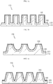
- FIG. 1a to FIG. 1e are schematic views illustrating various embodiments of the lithium electrode according to the present disclosure.
- the lithium electrode 100, 200, 300, 400, 500 includes: a current collector 110, 210, 310, 410, 510 having a surface irregularity structure provided with a top surface; a lithium metal layer 120, 220, 320, 420, 520 disposed outside of the portion except the top surface of the surface irregularity structure in the current collector; an electron-insulating protective layer 130, 230, 330, 430, 530 disposed outside of the lithium metal layer; and a lithium ion-isolating layer 140, 240, 340, 440, 540 disposed on the top surface of the surface irregularity structure of the current collector, in the upper side of the lithium metal layer and in the upper side of the electron-insulating protective layer.
- the lithium ion-isolating layer may be formed merely on the top surface of the surface irregularity structure of the current collector.
- the electron-insulating layer includes a non-porous layer 31 capable of transporting lithium ions but inhibiting growth of dendritic lithium by virtue of the absence of pores, and a polymer porous layer 32 capable of adjusting the direction of dendritic lithium growth toward the inside even if dendritic lithium is grown.
- the term 'outside' refers to the external region of the corresponding portion and covers the portion that is in contact with the surface of the corresponding portion and the portion spaced apart from the surface of the corresponding portion. In the latter case, another layer may be interposed between the corresponding layer and the portion spaced apart therefrom.
- the term 'upper side' means the portion disposed at the uppermost position in the height direction of the corresponding portion.
- non-porous layer means a layer free from pores, and will be further defined by the method described hereinafter.
- the current collector used for the lithium electrode has a surface irregularity structure provided with a top surface.
- the surface irregularity structure is provided with protrusions formed upwardly from the current collector, and grooves formed in the lateral side of the protrusions.
- the vertical sections of the protrusions have at least one shape selected from tetragonal, trapezoidal, cross and polygonal shapes
- the vertical shapes of the grooves have at least one shape selected from semi-circular, sector-like, triangular, tetragonal, dumbbell-like and polygonal shapes.
- the current collector patterned with various shapes of surface irregularity structures may provide three-dimensional electrodes by forming an electrode layer and the other functional layers thereon in the directions toward the outside and upper side. It is possible to control the direction of dendritic lithium growth through the patterns. Since a space is formed in the gap among the surface irregularity structures forming the patterns, it is possible to alleviate volumetric swelling of the electrode layer occurring in charge/discharge processes, and thus to prevent the structural collapse of the electrode. It is also possible to impart flexibility during the manufacture of a battery by virtue of the use of the patterned current collector.
- the surface irregularity structure may be formed by the conventional known patterning processes.
- the current collector is coated with a patterned film, the coated current collector is dipped in an etching solution suitable for the material forming the current collector to carry out etching, and then the patterned film is removed to form a pattern on the current collector.
- various patterning methods may be used.
- the surface irregularity structure has an average width of about 5-5,000 ⁇ m and an average height of about 1-5,000 ⁇ m to form a micropattern, but is not limited thereto.
- the current collector may be made of from stainless steel, aluminum, nickel, titanium, baked carbon, copper; stainless steel surface-treated with carbon, nickel, titanium, silver, gold or platinum; aluminum-cadmium alloy; a non-conductive polymer surface-treated with a conductive material; a non-conductive polymer surface-treated with a metal; or a conductive polymer.
- a current collector made of copper it is preferred to use.
- the lithium metal layer 120, 220, 320, 420, 520 is formed on the current collector.
- the lithium metal layer may be formed through vapor deposition, electroplating or lamination of a lithium-based active material capable of realizing high capacity in the portion except the top surface of the surface irregularity structure.
- the vapor deposition, electroplating and lamination may be formed by various methods known to those skilled in the art.
- the lithium metal layer may have a thickness of 1-2,000 ⁇ m. As the thickness is increased, the reversible capacity of a negative electrode is increased.
- the lithium-based active material that may be used herein includes lithium, lithium oxide, lithium alloy and lithium alloy oxide, particularly lithium.
- the electron-insulating protective layer is formed on the surface of the lithium metal layer.
- the electron-insulating protective layer has a dual layer structure including a non-porous layer 31 transporting lithium ions and having no pores, and a polymer porous layer 32.
- Both the non-porous layer 31 and the polymer porous layer 32 include a material which cannot conduct electrons, and thus have electron insulating property.
- the non-porous layer 31 and the polymer porous layer 32 having electron insulating property can prevent reaction of Li ions intercalated/deintercalated into/from the lithium metal layer with electrons and deposition of Li, i.e., growth of dendritic lithium.
- the non-porous layer 31 is a layer capable of transporting lithium ions while not conducting electrons.
- the term 'non-porous layer' means a layer having a true density value of 1.8-2.1 g/cm 3 when the true density is determined by the method as described hereinafter.
- the true density can be determined as follows.
- the mass (m1) of a side tube-attached specific gravity bottle having an inner volume of about 40 mL is measured precisely.
- a sample is introduced to the bottom of the specific gravity bottle evenly to a thickness of about 10 mm, and then the mass (m2) is measured precisely.
- 1-butanol is added mildly thereto to a depth of about 20 mm from the bottom.
- light vibration is applied to the specific gravity bottle and disappearance of large air bubbling is checked.
- the specific gravity bottle is introduced to a desiccator and evacuated gradually to 2.0-2.7 kPa.
- the specific gravity bottle is maintained at the same pressure for 20 minutes and removed from the desiccator after generation of air bubbles is stopped, and then 1-butanol is added thereto again.
- the specific gravity bottle is closed with a stopper and immersed in a thermostat water tank (controlled to a temperature of 30 ⁇ 0.03°C) for 15 minutes or more, and then the liquid surface of 1-butanol is adjusted to the tag line. Then, the specific gravity bottle is removed and the external part thereof is wiped well. After that, the specific gravity bottle is cooled to room temperature and the weight (m4) is measured precisely. Then, the same specific gravity bottle is filled with 1-butanol alone and immersed in a thermostat water tank in the same manner as described above. After adjusting to the tag line, the weight (m3) of the specific gravity bottle is measured.
- distilled water from which dissolved gases are removed by boiling right before its use, is received in a specific gravity bottle, and the specific gravity bottle is immersed in a thermostat water tank in the same manner as described above.
- the weight (m5) of the specific gravity bottle is measured in the same manner as described above.
- the non-porous layer may include an inorganic solid electrolyte and an electrolyte-swelling polymer.
- the non-porous layer 31 may be formed on the outside of the lithium metal layer through thin film coating processes, such as vapor deposition, coating, lamination, or the like.
- the non-porous layer is free from pores. More particularly, the non-porous layer has a true density value of 1.8-2.1 g/cm 3 and may be formed by the CIP process as described hereinafter.
- the non-porous layer may have a thickness of 1-500 nm.
- the non-porous layer is a thin film coating layer having a small thickness, it is possible to transport lithium ions even in the absence of pores.
- the non-porous layer may have a modulus of 0.1-1 GPa, preferably 0.8-1 GPa. In this case, the non-porous layer ensures a predetermined strength, and thus can inhibit growth of dendritic lithium physically.
- the non-porous layer since the non-porous layer has electron insulating property, it does not conduct electrons (e - ). Thus, it is possible to inhibit growth of dendritic lithium more efficiently on the surface of the corresponding layer.
- the organic/inorganic composite non-porous layer has electroconductivity, Li + is reduced when it meets an electron (e - ). In this case, a large amount of Li + participates in the irreversible reaction in order to stabilize the reduced interface.
- dendritic lithium is grown, non-uniform dendrite formation occurs due to the localization of electrons (e - ) to cause generation of a large amount of dead Li. Such a phenomenon causes degradation of the life characteristics of a battery.
- the inorganic solid electrolyte and the electrolyte-swelling polymer may be used at a ratio of 70:30 to 98:2, 75:25 to 95:5, or 80:20 to 90:10. Within the above-defined range, the non-porous layer shows an excellent effect of transporting lithium ions while not conducting electrons.
- the inorganic solid electrolyte functions as a medium through which lithium ions are transported, and may include an oxide-based, phosphate-based, nitride-based or a sulfide-based electrolyte, or a combination of two or more of them.
- the oxide-based inorganic solid electrolyte may be any one selected from the group consisting of lithium lanthanum titanates (LLTO), lithium lanthanum zirconium oxides (LLZO), lithium super ionic conductors (LISICON) and a combination thereof.
- the phosphate-based inorganic solid electrolyte may be any one selected from the group consisting of lithium-aluminum-titanium-phosphates (LATP), lithium-aluminum-germanium-phosphates (LAGP) and a combination thereof.
- LATP lithium-aluminum-titanium-phosphates
- LAGP lithium-aluminum-germanium-phosphates
- the nitride-based inorganic solid electrolyte may be lithium phosphorus oxynitride (LiPON), and the sulfide-based inorganic solid electrolyte may include any one selected from the group consisting of Li 10 GeP 2 S 12 , Li 2 S-P 2 S 5 , Li 2 S-P 2 S 5 -LiI, Li 2 S-P 2 S 5 -Li 2 O, Li 2 S-P 2 S 5 -Li 2 O-LiI, Li 2 S-SiS 2 , Li 2 S-SiS 2 -LiI, Li 2 S-SiS 2 -LiBr, Li 2 S-SiS 2 -LiCl, Li 2 S-SiS 2 -B 2 S 3 -LiI, Li 2 S-SiS 2 -P 2 S 5 -LiI, Li 2 S-B 2 S 3 , Li 2 S-P 2 S 5 -ZmSn (wherein each of m
- the electrolyte-swelling polymer undergoes a swelling phenomenon by which its volume is increased after it absorbs an electrolyte.
- a swelling phenomenon by which its volume is increased after it absorbs an electrolyte.
- Such an electrolyte-swelling polymer may include a polymer capable of transporting lithium ions after being swelled with an electrolyte while not conducting electrons, and particular examples of the polymer include a polyolefin-based, polyester-based, polyacryl-based, polyamide-based, polyurethane-based, cellulose-based, hydrocarbon-based or a polyol-based polymer, or a combination of two or more of them.
- examples of the polymer swelled with an electrolyte include, but are not limited to: polyvinylidene fluoride-co-hexafluoropropylene, polyvinylidene fluoride-co-trichloroethylene, polymethyl methacrylate, polybutyl acrylate, polyacrylonitrile, polyvinyl pyrrolidone, polyvinyl acetate, polyethylene-co-vinyl acetate, polyethylene oxide, polyarylate, cellulose acetate, cellulose acetate butyrate, cellulose acetate propionate, cyanoethylpullulan, cyanoethyl polyvinyl alcohol, cyanoethyl cellulose, cyanoethyl sucrose, pullulan, carboxymethyl cellulose, or the like.
- non-porous layer may further include a non-dielectric inorganic material in order to ensure the mechanical rigidity and ion conductivity of the protective layer.
- the non-dielectric inorganic material may include Al 2 O 3 , SnO 2 , Cu 3 N 2 , CeO 2 , MgO, NiO, CaO, ZnO, ZrO 2 , Y 2 O 3 , TiO 2 , SiC, Li 3 N or a combination of two or more of them.
- the polymer porous layer serves as an electrolyte carrier in order to supply a sufficient amount of electrolyte to the electrode surface.
- the polymer porous layer may be formed by stacking a polymer film capable of being swelled with an electrolyte and having a porous structure on the outside of the non-porous layer, simultaneously with the non-porous layer or sequentially.
- the polymer porous layer may have a thickness of 1-1,000 ⁇ m.
- the polymer porous layer may be formed to a larger thickness as compared to the non-porous layer and has flexibility.
- the polymer contained in the polymer porous layer is not particularly limited, as long as it can be swelled with an electrolyte and can provide a porous structure through polymer phase separation.
- Typical examples of the polymer include polyurethane having a sponge type structure.
- the polymer porous layer includes a polymer which can be swelled with an electrolyte and has a porous structure, it is possible to inhibit non-uniform supply of lithium ions while providing a sufficient amount of electrolyte to the surface of the lithium metal layer by virtue of its swelling phenomenon.
- the polymer porous layer can induce the direction of dendritic lithium growth through the porous structure toward the inner part of the surface of the polymer porous layer, not the counter electrode.
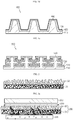
- the electron insulating protective layer 230 formed on the lithium metal layer 220 includes both the non-porous layer 31 and the polymer porous layer 32 ( FIG. 3a ), it is possible to prevent dendritic lithium grown from the lithium metal layer 220 through the non-porous layer 31 from being in contact with the counter electrode 260 through the separator 250 by inducing the growth of dendritic lithium toward the inner part of the polymer porous layer 32 along the surface thereof.
- the polymer porous layer 32 has an asymmetric structure in which it has a relatively large pore size at the interface with the non-porous layer 31 and the pore size is decreased toward the upper part or vice versa, it is possible to induce the growth of dendritic lithium toward the inner part of the polymer porous layer 32.
- Such a change in the battery may be monitored with ease through the internal resistance of the battery. Therefore, it is possible to improve the safety against explosion during the use of the battery.
- dendritic lithium rapidly passes through the non-porous layer 31 from the lithium metal layer 220 and rapidly grows in a 'free-standing' form. Then, the dendritic lithium passes through the separator 250 and is in contact with the counter electrode 260 to cause an electrical short-circuit. In addition, growth of dead lithium is increased at the interface between the lithium metal layer and the non-porous layer 31, resulting in rapid degradation of the battery.
- the electron insulating protective layer may have a total thickness of 1-1,000 ⁇ m.
- the lithium ion-isolating layer 140, 240, 340, 440, 550 may be disposed on the top surface of the surface irregularity structure of the current collector, in the upper side of the lithium metal layer and in the upper side of the electron-insulating protective layer, or merely on the top surface of the surface irregularity structure of the current collector.
- the lithium ion-isolating layer may include a polymer which has electron insulating property and cannot transport lithium ions.
- the lithium ion-isolating polymer may include a polyolefin-based, polyester-based, polyamide-based or a polyurethane-based polymer, or a combination of two or more of them.
- the lithium ion-insulating polymer may be formed by using such polymers in a film-like shape through coating, vapor deposition, or the like.
- the lithium ion-isolating layer has electron insulating property so that electrons cannot arrive at the lithium ion-isolating layer, it is possible to inhibit reactions of lithium ions and to prevent dendritic lithium from growing upwardly.
- the lithium ion-isolating layer according to the present disclosure serves to prevent not only transport of electrons but also transport of lithium ions.
- the lithium ion-isolating layer may be disposed on the top surface of the surface irregularity structure of the current collector, in the upper side of the lithium metal layer and in the upper side of the electron-insulating protective layer, or merely on the top surface of the surface irregularity structure of the current collector.
- dendritic lithium even when dendritic lithium is grown, it is possible to induce the growth of dendritic lithium toward a direction between the lithium metal layer and the non-porous layer, or toward a direction substantially in parallel with the polymer porous layer inside of the polymer porous layer, by virtue of the above-mentioned electron insulating protective layer. As a result, it is possible to delay a short-circuit in the battery and to improve life characteristics of the battery.
- the lithium ion-isolating layer may be disposed 1) on the top surface of the surface irregularity structure of the current collector which is not coated with any one of the lithium metal layer and the electron insulating layer but exposed to the outside, 2) in the upper side of the lithium metal layer not coated with the electron insulating layer and disposed in the same direction as the top surface of the surface irregularity structure of the current collector, and 3) in the upper side of the electron insulating protective layer disposed in the same direction as the top surface of the surface irregularity structure of the current collector.
- the thickness of the lithium ion-isolating layer is not particularly limited, as long as it can control diffusion of lithium ions.
- the lithium ion-isolating layer may have a larger thickness as compared to the organic/inorganic composite non-porous layer.
- the lithium metal electrode according to the present disclosure may be obtained by the following method, but is not limited thereto.
- a current collector having a surface irregularity structure provided with a top surface is prepared.
- the surface irregularity structure may be formed by using a conventional patterning process.
- a lithium metal layer is formed on the external surface of the current collector except the top surface of the surface irregularity structure of the current collector.
- the lithium metal layer may be formed through vapor deposition, plating or lamination of a lithium active material.
- slurry for forming a non-porous layer is coated and dried on the outside of the lithium metal layer to form a precursor of non-porous layer.
- the slurry for forming a non-porous layer is prepared by introducing the above-described inorganic solid electrolyte and electrolyte-swelling polymer, followed by agitation, and is coated and dried according to a conventional method.
- slurry for forming a polymer porous layer is coated and dried on the outside of the precursor of non-porous layer.
- the slurry for forming a polymer porous layer is prepared by introducing the above-mentioned polymer into a solvent.
- the polymer can be swelled with an electrolyte and has a porous structure.
- slurry for forming a lithium ion-isolating layer is coated and dried on the top surface of the surface irregularity structure of the current collector, in the upper side of the lithium metal layer and in the upper side of the electron insulating protective layer, or on the top surface of the surface irregularity structure of the current collector.
- the coating and drying may be carried out by using the conventional processes.
- the slurry for forming a lithium ion-isolating layer may be prepared by using a polymer which has electron insulating property and is not capable of transporting lithium ions, and particular examples of the polymer include polyolefin-, polyester-, polyamide- and polyurethane-based polymers.
- the precursor of lithium metal electrode to which the lithium ion-insulating layer is introduced is subjected to cold isostatic pressing (CIP) to form a non-porous layer.
- CIP cold isostatic pressing
- 'cold isostatic pressing' refers to a process of sealing the precursor of lithium metal electrode in a sealed rubber-made container and applying isostatic pressure to the container having the precursor of lithium metal electrode by using a vacuum pump capable of applying pressure uniformly.
- the isostatic pressure may range from ambient pressure to 300 MPa.
- the above-described lithium electrode according to the present disclosure includes a current collector patterned with a surface irregularity structure, a lithium metal layer, an electron insulating layer including a non-porous layer and a polymer porous layer, and a lithium ion-isolating layer.
- a current collector patterned with a surface irregularity structure
- a lithium metal layer patterned with a surface irregularity structure
- an electron insulating layer including a non-porous layer and a polymer porous layer
- a lithium ion-isolating layer a lithium ion-isolating layer.
- a lithium secondary battery including the above-described lithium electrode.
- the lithium secondary battery may be obtained by injecting a lithium salt-containing electrolyte to an electrode assembly including a cathode, an anode and a separator interposed between the cathode and the anode, wherein the anode may be the lithium electrode according to the present disclosure.
- the lithium secondary battery may have a cylindrical, prismatic, pouch-like, flexible or coin-like shape.
- the separator may be eliminated when forming the electrode assembly.
- a flexible secondary battery including the lithium electrode.
- the lithium electrode may be used as an internal electrode for a cable-type secondary battery. Reference can be made to following description of the flexible secondary battery for the constitutional elements other than the lithium electrode.
- cathode active material may include any type of active material particles selected from the group consisting of LiCoO 2 , LiNiO 2 , LiMn 2 O 4 , LiCoPO 4 , LiFePO 4 , LiNiMnCoO 2 and LiNi 1-x-y-z Co x M1 y M2 z O 2 (wherein each of M1 and M2 independently represents any one selected from the group consisting of Al, Ni, Co, Fe, Mn, V, Cr, Ti, W, Ta, Mg and Mo, each of x, y and z independently represents an atomic proportion of an element forming the oxides, and 0 ⁇ x ⁇ 0.5, 0 ⁇ y ⁇ 0.5, 0 ⁇ z ⁇ 0.5, 0 ⁇ x + y + z ⁇ 1), or a mixture of two or more of them.
- active material particles selected from the group consisting of LiCoO 2 , LiNiO 2 , LiMn 2 O 4 , LiCo
- the cathode may be obtained by dispersing an active material, binder, conductive material, or the like, to a solvent, such as N-methyl pyrrolidone, acetone or water to form slurry, coating the slurry onto a current collector and removing the solvent through drying.
- a solvent such as N-methyl pyrrolidone, acetone or water
- any coating process used conventionally in the art such as a slot die coating process, Mayer bar coating process, gravure coating process, dip coating process or a spray coating process, may be used.
- the separator may be a porous polymer film used conventionally as a separator for a lithium secondary battery.
- a porous polymer film obtained by using a polyolefin-based polymer such as ethylene homopolymer, propylene homopolymer, ethylene/butane copolymer, ethylene/hexane copolymer or ethylene/methacrylate copolymer may be used alone, or a stack of such polymers may be used.
- an insulating thin film having high ion permeability and mechanical strength may be used.
- the separator may include a safety reinforced separator (SRS) provided with an organic/inorganic porous coating layer including inorganic particles interconnected and fixed by means of a binder polymer and coated on the surface of a separator substrate, such as a porous polymer film to a small thickness.
- SRS safety reinforced separator
- a conventional porous nonwoven web such as a nonwoven web made of glass fibers having a high melting point or polyethylene terephthalate fibers may be used.
- the electrolyte includes a lithium salt and an organic solvent for dissolving the lithium salt.
- any lithium salt used conventionally for an electrolyte for a secondary battery may be used with no particular limitation.
- the anion of the lithium salt may be any one selected from the group consisting of F - , Cl - , Br - , I - , NO 3 - , N(CN) 2 - , BF 4 - , ClO 4 - , PF 6 - , (CF 3 ) 2 PF 4 - , (CF 3 ) 3 PF 3 - , (CF 3 ) 4 PF 2 - , (CF 3 ) 5 PF - , (CF 3 ) 6 P - , CF 3 SO 3 - , CF 3 CF 2 SO 3 - , (CF 3 SO 2 ) 2 N - , (FSO 2 ) 2 N - , CF 3 CF 2 (CF 3 ) 2 CO - , (CF 3 SO 2 ) 2 CH - , (SF 5 ) 3 C - , (CF 3 SO
- the organic solvent contained in the electrolyte may be a conventional solvent with no particular limitation.
- Typical examples of the organic solvent may be at least one selected from the group consisting of propylene carbonate, ethylene carbonate, diethyl carbonate, dimethyl carbonate, ethylmethyl carbonate, methylpropyl carbonate, dipropyl carbonate, dimethyl sulfoxide, acetonitrile, dimethoxyethane, diethoxyethane, vinylene carbonate, sulforane, gamma-butyrolactone, propylene sulfite and tetrahydrofuran.
- ethylene carbonate and propylene carbonate which are cyclic carbonates are preferred, since they are high-viscosity organic solvents and have a high dielectric constant, and thus dissociate the lithium salt in the electrolyte well.
- cyclic carbonates in combination with low-viscosity low-dielectric constant linear carbonates, such as dimethyl carbonate and diethyl carbonate, at an adequate ratio, it is possible to prepare an electrolyte having high electroconductivity more preferably.
- the electrolyte used according to the present disclosure may further include additives, such as an overcharge-preventing agent, contained in the conventional electrolytes.
- the lithium secondary battery according to the present disclosure may be obtained by interposing a separator between a positive electrode and a negative electrode to form an electrode assembly, introducing the electrode assembly into a battery casing, such as a pouch-like, cylindrical or prismatic battery casing, and injecting an electrolyte thereto.
- a battery casing such as a pouch-like, cylindrical or prismatic battery casing
- the stacked electrode assemblies may be immersed in an electrolyte, and the resultant structure may be introduced to and sealed in a battery casing to finish a lithium secondary battery.
- the lithium secondary battery may be a stacked, wound, stacked and folded or cable-type lithium secondary battery.
- the lithium secondary battery according to the present disclosure may be applied not only to a battery cell used as a power source for compact devices but also to a medium-to large-size battery module including a plurality of battery cells as a unit cell.
- Preferred examples of such medium- to large-size devices include electric vehicles, hybrid electric vehicles, plug-in hybrid electric vehicles, power storage systems, or the like.
- the lithium secondary battery according to the present disclosure may be useful for hybrid electric vehicles, new and renewable energy storage batteries, or the like, requiring high output.
- FIG. 4 is a schematic view illustrating the flexible secondary battery according to an embodiment of the present disclosure
- FIG. 5 is a sectional view of FIG. 4 .
- the flexible secondary battery 600 includes: an internal electrode provided with an internal current collector 610 and a lithium-containing internal electrode layer 620 surrounding the outside of the internal current collector 610; an electron-insulating protective layer 630 surrounding the outside of the internal electrode; an electron-insulating support 640 surrounding the outside of the electron-insulating protective layer; a separator layer 650 surrounding the outside of the electron-insulating support; and an external electrode provided with an external electrode layer 660 surrounding the outside of the separator layer and an external current collector 670 surrounding the outside of the external electrode layer.
- the flexible secondary battery 600 according to an embodiment of the present disclosure may further include a protective coating 680 outside of the external current collector 670.
- the flexible secondary battery according to an embodiment of the present disclosure has a predetermined shape of horizontal section and may have a linear structure elongated in the longitudinal direction to the horizontal direction.
- the flexible secondary battery may have flexibility and can be deformed freely.
- the term 'predetermined shape' refers to a shape not limited to a particular shape. Any shape may be used as long as it does not adversely affect the present disclosure.
- the term 'spiral' or 'helical' refers to a shape twisted and wound in a predetermined range and generally covers a shape similar to the shape of a general spring.
- the term 'outside' means the external region of the corresponding portion and covers both the portion that is in contact with the surface of the corresponding portion and the portion spaced apart from the corresponding portion. In the latter case, another layer may be interposed between the corresponding portion and the portion spaced apart therefrom.
- the internal electrode may be an anode which includes an internal current collector 610 and a lithium-containing internal electrode layer 620 surrounding the outside thereof.
- the internal current collector may be a linear wire-type current collector or an open structured current collector having an inner space.
- the term 'open structure' refers to a structure which has the open structure as a boundary surface and allows free mass transfer from the inside to the outside through the boundary surface. As a result, injection of an electrolyte may be facilitated through the internal current collector.
- the open structured current collector may be a spirally wound wire-type current collector, spirally wound sheet-type current collector, or two or more wire type current collectors wound spirally so that they may cross each other.
- the open structured internal current collector may be made of stainless steel, aluminum, nickel, titanium, baked carbon, copper; stainless steel surface-treated with carbon, nickel, titanium or silver; aluminum-cadmium alloy; a non-conductive polymer surface-treated with a conductive material; or a conductive polymer, copper being preferred.
- the current collector functions to collect the electrons generated by the electrochemical reaction of an electrode active material or to supply the electrons required for electrochemical reaction.
- a current collector uses a metal, such as copper or aluminum.
- a polymer current collector may be used instead of a metal current collector to accomplish weight lightening of a battery.
- the conductive material may be any one selected from the group consisting of polyacetylene, polyaniline, polypyrrole, polythiophene, polysulfur nitride, indium tin oxide (ITO), silver, palladium and nickel, and the conductive polymer may include polyacetylene, polyaniline, polypyrrole, polythiophene, polysulfur nitride, or the like.
- the conductive polymer may include polyacetylene, polyaniline, polypyrrole, polythiophene, polysulfur nitride, or the like.
- the type of non-conductive polymer used for the current collector there is no particular limitation in the type of non-conductive polymer used for the current collector.
- an internal electrode current collector core portion may be provided.
- the internal electrode current collector core portion may be made of carbon nanotubes, stainless steel, aluminum, nickel, titanium, baked carbon, copper; stainless steel surface-treated with carbon, nickel, titanium or silver; aluminum-cadmium alloy; a non-conductive polymer surface-treated with a conductive material; or a conductive polymer.
- a lithium ion-supplying core portion containing an electrolyte may be provided in the space formed inside of the open structured current collector.
- the electrolyte of the lithium ion-supplying core portion may pass through the internal current collector and arrive at the internal electrode active material layer and the external electrode active material layer. Therefore, there is no need for increasing the thickness of an electrolyte layer excessively. Rather, the electrolyte layer is not an essential constitutional element, and thus only a separator may be used selectively.
- the flexible secondary battery according to an embodiment of the present disclosure may be provided with a lithium ion-supplying core portion containing an electrolyte, and thus facilitates infiltration of the electrolyte into the electrode active material. Thus, it is possible to facilitate supply and exchange of lithium ions in an electrode, and thus to provide a battery with excellent capacity characteristics and cycle characteristics.
- the lithium ion-supplying core portion includes an electrolyte.
- an electrolyte there is no particular limitation in the electrolyte, it is preferred to use a non-aqueous electrolyte using ethylene carbonate (EC), propylene carbonate (PC), butylene carbonate (BC), vinylene carbonate (VC), diethyl carbonate (DEC), dimethyl carbonate (DMC), ethyl methyl carbonate (EMC), methyl formate (MF), ⁇ -butryolactone ( ⁇ -BL), sulfolane, methyl acetate (MA) or methyl propionate (MP); a gel polymer electrolyte using PEO, PVdF, PVdF-HFP, PMMA, PAN or PVAC; a solid electrolyte using PEO, polypropylene oxide (PPO), polyethylene imine (PEI), polyethylene sulfide (PES) or polyvinyl acetate (PVAC); or the like.
- EC ethylene carbon
- the electrolyte may further include a lithium salt, such as LiCl, LiBr, LiI, LiClO 4 , LiBF 4 , LiB 10 Cl 10 , LiPF 6 , LiCF 3 SO 3 , LiCF 3 CO 2 , LiAsF 6 , LiSbF 6 , LiAlCl 4 , CH 3 SO 3 Li, (CF 3 SO 2 ) 2 NLi, lithium chloroborate, lithium lower aliphatic carboxylate or lithium tetraphenylborate.
- the lithium ion-supplying core portion may include an electrolyte alone. In the case of a liquid electrolyte, a porous carrier may be used.
- a filler core portion may be formed.
- the filler core portion may include materials for improving various properties of the flexible secondary battery, other than the above-described materials forming the internal electrode current collector core portion and lithium ion-supplying core portion.
- the filler core portion may include polymer resins, rubber, inorganic materials, or the like, in various shapes, such as wire, fiber, powder, mesh, foam, or the like.
- the lithium-containing internal electrode layer 620 surrounds the outside of the internal current collector and may be formed by coating a lithium-based active material to realize high capacity. Any conventional coating processes may be used and particular examples thereof include electroplating or lamination processes.
- the lithium-containing internal electrode layer may have a thickness of 1-500 ⁇ m.
- lithium-based active material may include lithium, lithium oxides, lithium alloys and lithium alloy oxides, particularly lithium.
- the electron insulating protective layer 630 may be formed to surround the outside of the lithium-containing internal electrode layer 620.
- the electron insulating protective layer 630 has a dual layer structure including a non-porous layer 31 and a polymer porous layer 32, as described hereinabove with reference to the lithium metal electrode.
- the electron insulating support 640 may be provided in a wire-like, i.e. spring-like shape wound spirally on the outside of the electron insulating protective layer 630, as shown in FIG. 4 .
- the electron insulating support functions as a flexible framework of a battery provided between the internal electrode and the external electrode.
- the electron insulating support 640 may be provided in a mesh-like shape of hollow shape.
- the electron insulating support 640 may be made of a polymer or polymer-coated metal.
- the polymer may be a polyolefin-, polyester-, polyacryl-, polyamide- or a polyurethane-based polymer
- the metal may be a metal forming the internal current collector or external current collector, wherein the metal surface is coated with a non-conductive polymer.
- the pitch i.e. winding interval
- the pitch may be constant or may be decreased or increased gradually.
- the term 'pitch' means the interval between one coil and another coil in a general coil spring shape, and refers to the winding interval in a wound wire-type support.
- FIG. 8 illustrates that the thickness of the wire-type electron insulating support as shown in FIG. 7 can be controlled.
- the thickness of the wire-type support may be controlled within a range of 100 ⁇ m- 3 mm. Therefore, it is possible to control the size of the space between the pitches, and thus to delay degradation of the life of a battery caused by growth of dendritic lithium.
- the separator layer 650 may be an electrolyte layer or a separator.
- the separator layer may be formed by extrusion coating in terms of the characteristics of a linear flexible secondary battery.
- the separator layer may be formed by winding the separator around the electron insulating support.
- the electrolyte layer functions as an ion channel, and may be made of a gel polymer electrolyte using PEO, PVdF, PVdF-HFP, PMMA, PAN or PVAC; or a solid electrolyte using PEO, polypropylene oxide (PPO), polyethylene imine (PEI), polyethylene sulfide (PES) or polyvinyl acetate (PVAC).
- PEO polypropylene oxide
- PEI polyethylene imine
- PES polyethylene sulfide
- PVAC polyvinyl acetate
- the electrolyte layer may further include a lithium salt in order to improve ion conductivity and reaction rate.
- the lithium salt may be selected from LiCl, LiBr, LiI, LiClO 4 , LiBF 4 , LiB 10 Cl 10 , LiPF 6 , LiCF 3 SO 3 , LiCF 3 CO 2 , LiAsF 6 , LiSbF 6 , LiAlCl 4 , CH 3 SO 3 Li, (CF 3 SO 2 ) 2 NLi, lithium chloroborate, lithium lower aliphatic carboxylate, lithium tetraphenylborate and a combination thereof.
- the separator may be a porous polymer substrate made of a polyolefin polymer selected from the group consisting of an ethylene homopolymer, propylene homopolymer, ethylene-butene copolymer, ethylene-hexene copolymer and ethylene-methacrylate copolymer; a porous polymer substrate made of a polymer selected from the group consisting of polyester, polyacetal, polyamide, polycarbonate, polyimide, polyetherether ketone, polyether sulfone, polyphenylene oxide, polyphenylene sulfide and polyethylene naphthalate; a porous substrate formed of a mixture of inorganic particles and a binder polymer; or a separator provided with a porous coating layer formed of a mixture of inorganic particles and a binder polymer on at least one surface of the porous polymer substrate.
- a porous polymer substrate made of a polyolefin polymer selected from the group consisting of an ethylene homo
- the external electrode may be a cathode which includes an external electrode layer 660 and an external current collector 670 surrounding the outside thereof.
- the external electrode layer 660 may be formed by coating and drying slurry containing an active material, a conductive material and a binder.
- the coating may be carried out by dip coating, or by using a comma coater or slot die coater.
- the active material may be any one selected from the group consisting of LiCoO 2 , LiNiO 2 , LiMn 2 O 4 , LiCoPO 4 , LiFePO 4 , LiNiMnCoO 2 and LiNi 1-x-y-z Co x M1 y M2 z O 2 (wherein each of M1 and M2 independently represents any one selected from the group consisting of Al, Ni, Co, Fe, Mn, V, Cr, Ti, W, Ta, Mg and Mo, each of x, y and z independently represents an atomic proportion of an element forming the oxides, and 0 ⁇ x ⁇ 0.5, 0 ⁇ y ⁇ 0.5, 0 ⁇ z ⁇ 0.5, 0 ⁇ x + y + z ⁇ 1).
- the conductive material that may be used herein includes carbon black, acetylene black, ketjen black, carbon fibers, or the like.
- the binder that may be used herein includes polyvinylidene fluoride-co-hexafluoropropylene, polyvinylidene fluoride, polyacrylonitrile, polymethyl methacrylate, polyvinyl alcohol, carboxymethyl cellulose (CMC), starch, hydroxypropyl cellulose, regenerated cellulose, polyvinyl pyrroldone, tetrafluoroethylene, polyethylene, polypropylene, polyacrylate, styrene-butyrene rubber (SBR), or the like.
- CMC carboxymethyl cellulose
- SBR styrene-butyrene rubber
- the external current collector 670 may be a pipe-type, wound wire-type, wound sheet-type or mesh-type current collector, and may be made of stainless steel, aluminum, nickel, titanium, baked carbon or copper; stainless steel surface-treated with carbon, nickel, titanium or silver; aluminum-cadmium alloy; a non-conductive polymer surface-treated with a conductive material; a conductive polymer; metal paste including metal powder which is Ni, Al, Au, Pd/Ag, Cr, Ta, Cu, Ba or ITO; or carbon paste containing carbon powder which is graphite, carbon black or a carbon nanotube.
- At least one additional separator layer and internal electrode may be incorporated successively between the separator layer and the external electrode.
- the flexible secondary battery according to the present disclosure may be further provided with a protective coating 680.
- the protective coating is an insulating body and is formed on the outer surface of the external electrode in order to protect the electrode from the moisture in the air and external impacts.
- the protective coating may include a conventional polymer resin including a waterproof layer.
- the polymer resin may include PET, PVC, HDPE or epoxy resin
- the waterproof layer may include aluminum or a liquid crystal polymer having excellent waterproof property.
- the flexible secondary battery according to the present disclosure may include two or more internal electrodes. Therefore, as shown in FIG. 9a to FIG. 9c , the flexible secondary battery 700, 800, 900 according to another embodiment of the present disclosure includes: two or more internal electrodes each provided with an internal current collector 710, 810, 910 and a lithium-containing internal electrode layer 720, 820, 920 surrounding the outside of the internal current collector; an electron-insulating protective layer 730, 830, 930 surrounding the outside of the two or more internal electrodes; an electron-insulating support 740, 840, 940 surrounding the outside of the electron-insulating protective layer; a separator layer 750, 850, 950 surrounding the outside of the electron-insulating support; and an external electrode provided with an external electrode layer 760, 860, 960 surrounding the outside of the separator layer and an external current collector 770, 870, 970 surrounding the outside of the external electrode layer.
- the flexible secondary battery 700, 800, 900 may further include a protective coating 780, 880, 980.
- Each electron insulating protective layer 730, 830, 930 may include an organic/inorganic composite non-porous layer and a polymer porous layer surrounding the outer surface thereof. Particular description of the electron insulating protective layer is the same as described above.
- the two or more internal electrodes may be disposed in parallel with each other ( FIG. 9a to FIG. 9c ), or may be disposed in a spirally twisted form while crossing each other ( FIG. 10 ).
- the flexible secondary battery 700, 800, 900 is provided with an internal electrode having a plurality of electrodes, it is possible to control the loading amount of an electrode layer and battery capacity by adjusting the number of internal electrodes.
- sine the flexible secondary battery is provided with a plurality of electrodes, it is possible to prevent disconnection.
- the flexible secondary battery as described above uses a lithium-containing electrode layer as an internal electrode to realize high capacity, and is provided with an electron insulating protective layer and electron insulating support outside of the lithium-containing electrode layer to inhibit non-uniform growth of dendritic lithium and to ensure a channel through which an electrolyte moves smoothly.
- the flexible secondary battery has improved safety and excellent life characteristics.
- the flexible battery according to the present disclosure may be used not only for a battery cell used as a power source for a compact device but also as a unit cell of a medium- to large-size battery module including a plurality of battery cells.
- the flexible lithium secondary battery according to the present disclosure may be used advantageously as a power source in various wearable environments.
Landscapes
- Chemical & Material Sciences (AREA)
- Chemical Kinetics & Catalysis (AREA)
- Electrochemistry (AREA)
- General Chemical & Material Sciences (AREA)
- Engineering & Computer Science (AREA)
- Manufacturing & Machinery (AREA)
- Materials Engineering (AREA)
- Composite Materials (AREA)
- Inorganic Chemistry (AREA)
- Secondary Cells (AREA)
- Battery Electrode And Active Subsutance (AREA)
- Cell Electrode Carriers And Collectors (AREA)
Abstract
Description
- The present disclosure relates to a lithium electrode, more particularly a three-dimensional lithium electrode having improved safety and excellent life characteristics and rate characteristics, and a lithium secondary battery and flexible secondary battery including the same.
- The present application claims priority to Korean Patent Application No.
10-2017-0114598 filed on September 7, 2017 10-2017-0114599 filed September 7, 2017 - As technological development and a need for mobile instruments have increased, researchable secondary batteries which can be downsized and provided with high capacity have been increasingly in demand. In addition, among such secondary batteries, lithium secondary batteries having high energy density and voltage have been commercialized and used widely.
- A lithium secondary battery has a structure in which an electrode assembly including a cathode, an anode and a separator interposed between the cathode and the anode is stacked or wound, and is formed by introducing the electrode assembly into a battery casing and injecting a non-aqueous electrolyte thereto. The lithium secondary battery generates electric energy by oxidation/reduction upon the intercalation/deintercalation of lithium ions into/from the cathode and the anode.
- In general, when using lithium metal as an active material for an electrode, it is advantageous in that high capacity can be realized. However, while a battery repeats charge/discharge cycles, lithium metal is dissolved or deposited by its ionization and is grown in the form of dendritic lithium. This results in a short-circuit in the battery and dead lithium. Thus, there are problems in that the battery has poor stability and short life.
- Therefore, various attempts have been made in order to inhibit growth of dendritic lithium. However, the above-mentioned problems are not solved completely to date.
- The present disclosure is designed to solve the problems of the related art, and therefore the present disclosure is directed to providing a three-dimensional lithium electrode which inhibits non-uniform growth of dendritic lithium to improve the safety of a battery and to provide a battery with excellent life characteristics and rate characteristics.
- The present disclosure is also designed to provide a lithium secondary battery and flexible battery including the lithium electrode.
- In one aspect of the present disclosure, there is provided a lithium metal electrode according to any one of the following embodiments.
- According to the first embodiment, there is provided a lithium metal electrode including:
- a current collector having a surface irregularity structure provided with a top surface;
- a lithium metal layer disposed outside of the portion except the top surface of the surface irregularity structure in the current collector;
- an electron-insulating protective layer disposed outside of the lithium metal layer; and
- a lithium ion-isolating layer disposed on the top surface of the surface irregularity structure of the current collector, or on the top surface of the surface irregularity structure of the current collector, in the upper side of the lithium metal layer and in the upper side of the electron-insulating protective layer,
- wherein the electron-insulating layer includes a non-porous layer transporting lithium ions and having no pores, and a polymer porous layer disposed outside thereof.
- According to the second embodiment, there is provided the lithium metal electrode as defined in the first embodiment, wherein the surface irregularity structure is provided with protrusions formed upwardly from the current collector, and grooves formed in the lateral side of the protrusions.
- According to the third embodiment, there is provided the lithium metal electrode as defined in the second embodiment, wherein the vertical sections of the protrusions have at least one shape selected from tetragonal, trapezoidal and cross shapes, and the vertical shapes of the grooves have at least one shape selected from semi-circular, sector-like, triangular, tetragonal and dumbbell-like shapes.
- According to the fourth embodiment, there is provided the lithium metal electrode as defined in any one of the first to the third embodiments, wherein the non-porous layer includes an inorganic solid electrolyte and an electrolyte-swelling polymer.
- According to the fifth embodiment, there is provided the lithium metal electrode as defined in the fourth embodiment, wherein the inorganic solid electrolyte and the electrolyte-swelling polymer are used at a weight ratio of 70:30 to 98:2.
- According to the sixth embodiment, there is provided the lithium metal electrode as defined in the fourth or the fifth embodiment, wherein the inorganic solid electrolyte includes an oxide-based, phosphate-based, nitride-based or a sulfide-based electrolyte, or a combination of two or more of them.
- According to the seventh embodiment, there is provided the lithium metal electrode as defined in any one of the fourth to the sixth embodiments, wherein the electrolyte-swelling polymer includes a polyolefin-based, polyester-based, polyacryl-based, polyamide-based, polyurethane-based, cellulose-based, hydrocarbon-based or a polyol-based polymer, or a combination of two or more of them.
- According to the eighth embodiment, there is provided the lithium metal electrode as defined in any one of the fourth to the seventh embodiments, wherein the non-porous layer further includes a non-dielectric inorganic material including Al2O3, SnO2, Cu3N2, CeO2, MgO, NiO, CaO, ZnO, ZrO2, Y2O3, TiO2, SiC or Li3N, or a combination of two or more of them.
- According to the ninth embodiment, there is provided the lithium metal electrode as defined in any one of the first to the eighth embodiments, wherein the polymer porous layer includes a polymer film having a porous structure capable of being swelled with an electrolyte.
- According to the tenth embodiment, there is provided the lithium metal electrode as defined in the ninth embodiment, wherein the polymer film having a porous structure capable of being swelled with an electrolyte includes sponge type polyurethane.
- According to the eleventh embodiment, there is provided the lithium metal electrode as defined in any one of the first to the tenth embodiments, wherein the electron-insulating protective layer has a thickness of 1-1,000 µm.
- According to the twelfth embodiment, there is provided the lithium metal electrode as defined in any one of the first to the eleventh embodiments, wherein the non-porous layer in the electron-insulating protective layer has a thickness of 1-500 nm.
- According to the thirteenth embodiment, there is provided the lithium metal electrode as defined in any one of the first to the twelfth embodiments, wherein the lithium ion-isolating layer includes a polyolefin-based, polyester-based, polyamide-based or a polyurethane-based polymer, or a combination of two or more of them.
- In another aspect of the present disclosure, there is also provided a lithium secondary battery according to any one of the following embodiments.
- According to the fourteenth embodiment, there is provided a lithium secondary battery including a cathode, an anode, a separator interposed between the cathode and the anode, and an electrolyte, wherein the anode is the lithium metal electrode as defined in any one of the first to the thirteenth embodiments.
- According to the fifteenth embodiment, there is provided the lithium secondary battery as defined in the fourteenth embodiment, which is a cylindrical, prismatic, pouch-type, flexible type or a coin-type lithium secondary battery.
- In still another aspect of the present disclosure, there is provided a flexible secondary battery according to any one of the following embodiments.
- According to the sixteenth embodiment, there is provided a flexible secondary battery including:
- an internal electrode provided with an internal current collector and a lithium-containing internal electrode layer surrounding the outside of the internal current collector;
- an electron-insulating protective layer surrounding the outside of the internal electrode, and provided with a non-porous layer including an inorganic solid electrolyte and an electrolyte-swelling polymer and a polymer porous layer surrounding the external surface of the non-porous layer;
- an electron-insulating support surrounding the outside of the electron-insulating protective layer;
- a separator layer surrounding the outside of the electron-insulating support; and
- an external electrode provided with an external electrode layer surrounding the outside of the separator layer and an external current collector surrounding the outside of the external electrode layer.
- According to the seventeenth embodiment, there is provided the flexible secondary battery as defined in the sixteenth embodiment, wherein the inorganic solid electrolyte includes an oxide-based, phosphate-based, nitride-based or a sulfide-based electrolyte, or a combination of two or more of them.
- According to the eighteenth embodiment, there is provided the flexible secondary battery as defined in the sixteenth or the seventeenth embodiments, wherein the electrolyte-swelling polymer includes a polyolefin-based, polyester-based, polyacryl-based, polyamide-based, polyurethane-based, cellulose-based, hydrocarbon-based or a polyol-based polymer, or a combination of two or more of them.
- According to the nineteenth embodiment, there is provided the flexible secondary battery as defined in any one of the sixteenth to the eighteenth embodiments, wherein the electron-insulating support is a wound wire-type support surrounding the outside of the electron-insulating protective layer, the wound wire-type support has a thickness of 100 µm-3 mm, and the wound wire-type support has a pitch (i.e. winding interval) of 1 µm-1 cm.
- In yet another aspect of the present disclosure, there is provided a flexible secondary battery according to the following embodiment.
- According to the twentieth embodiment, there is provided a flexible secondary battery including:
- two or more internal electrodes each provided with an internal current collector and a lithium-containing internal electrode layer surrounding the outside of the internal current collector;
- an electron-insulating protective layer provided with a non-porous layer surrounding the outside of each of the two or more internal electrodes and a polymer porous layer surrounding the external surface of the non-porous layer;
- an electron-insulating support surrounding the outside of the electron-insulating protective layer;
- a separator layer surrounding the outside of the electron-insulating support; and
- an external electrode provided with an external electrode layer surrounding the outside of the separator layer and an external current collector surrounding the outside of the external electrode layer.
- The lithium electrode according to the present disclosure is provided with a current collector patterned with a surface irregularity structure, and thus shows flexibility and prevents a collapse of the electrode structure caused by volumetric swelling of lithium metal. In addition, the lithium electrode is provided with an electron-insulating protective layer including a non-porous layer and a polymer porous layer, and thus inhibits non-uniform growth of dendritic lithium, improves safety and provides excellent life characteristics and rate characteristics.
-
-
FIG. 1a to FIG. 1e are schematic views illustrating various embodiments of the lithium electrode according to the present disclosure. -
FIG. 2 is a schematic view illustrating the structure of the electron-insulating protective layer used in the lithium electrode according to an embodiment of the present disclosure. -
FIG. 3a illustrates a direction of dendritic lithium growth when the electron-insulating protective layer of the lithium electrode includes a polymer porous layer according to the present disclosure. -
FIG. 3b illustrates a direction of dendritic lithium growth when no polymer porous layer is present in the electron-insulating protective layer. -
FIG. 4 is a schematic view illustrating the structure of the flexible secondary battery according to an embodiment of the present disclosure. -
FIG. 5 is a sectional view illustrating the flexible secondary battery according to an embodiment of the present disclosure. -
FIG. 6 illustrates the definition of the term 'pitch' used in the present disclosure. -
FIG. 7 illustrates a controllable pitch in the wire-type electron-insulating support provided in the flexible secondary battery according to an embodiment of the present disclosure. -
FIG. 8 illustrates a controllable thickness of the wire-type electron-insulating support as shown inFIG. 7 . -
FIG. 9a to FIG. 9c are sectional views illustrating the flexible secondary battery including two or more internal electrodes according to another embodiment of the present disclosure. -
FIG. 10 is a schematic view illustrating three wire-type internal electrodes twisted spirally while crossing each other in the flexible secondary battery according to still another embodiment of the present disclosure. - Hereinafter, preferred embodiments of the present disclosure will be described in detail with reference to the accompanying drawings. It should be understood that the terms used in the specification and the appended claims should not be construed as limited to general and dictionary meanings, but interpreted based on the meanings and concepts corresponding to technical aspects of the present disclosure on the basis of the principle that the inventor is allowed to define terms appropriately for the best explanation.
- In addition, the description proposed herein is just a preferable example for the purpose of illustrations only, not intended to limit the scope of the disclosure, so it should be understood that other equivalents and modifications could be made thereto without departing from the scope of the disclosure.
-
FIG. 1a to FIG. 1e are schematic views illustrating various embodiments of the lithium electrode according to the present disclosure. - Referring to
FIG. 1a to FIG. 1e , thelithium electrode current collector lithium metal layer protective layer layer FIG. 2 , the electron-insulating layer includes anon-porous layer 31 capable of transporting lithium ions but inhibiting growth of dendritic lithium by virtue of the absence of pores, and a polymerporous layer 32 capable of adjusting the direction of dendritic lithium growth toward the inside even if dendritic lithium is grown. - As used herein, the term 'outside' refers to the external region of the corresponding portion and covers the portion that is in contact with the surface of the corresponding portion and the portion spaced apart from the surface of the corresponding portion. In the latter case, another layer may be interposed between the corresponding layer and the portion spaced apart therefrom.
- As used herein, the term 'upper side' means the portion disposed at the uppermost position in the height direction of the corresponding portion.
- As used herein, the term 'non-porous layer' means a layer free from pores, and will be further defined by the method described hereinafter.
- According to the present disclosure, the current collector used for the lithium electrode has a surface irregularity structure provided with a top surface. The surface irregularity structure is provided with protrusions formed upwardly from the current collector, and grooves formed in the lateral side of the protrusions. In addition, the vertical sections of the protrusions have at least one shape selected from tetragonal, trapezoidal, cross and polygonal shapes, and the vertical shapes of the grooves have at least one shape selected from semi-circular, sector-like, triangular, tetragonal, dumbbell-like and polygonal shapes.
- Thus, the current collector patterned with various shapes of surface irregularity structures may provide three-dimensional electrodes by forming an electrode layer and the other functional layers thereon in the directions toward the outside and upper side. It is possible to control the direction of dendritic lithium growth through the patterns. Since a space is formed in the gap among the surface irregularity structures forming the patterns, it is possible to alleviate volumetric swelling of the electrode layer occurring in charge/discharge processes, and thus to prevent the structural collapse of the electrode. It is also possible to impart flexibility during the manufacture of a battery by virtue of the use of the patterned current collector.
- The surface irregularity structure may be formed by the conventional known patterning processes. For example, the current collector is coated with a patterned film, the coated current collector is dipped in an etching solution suitable for the material forming the current collector to carry out etching, and then the patterned film is removed to form a pattern on the current collector. In addition to this, various patterning methods may be used.
- The surface irregularity structure has an average width of about 5-5,000 µm and an average height of about 1-5,000 µm to form a micropattern, but is not limited thereto.
- The current collector may be made of from stainless steel, aluminum, nickel, titanium, baked carbon, copper; stainless steel surface-treated with carbon, nickel, titanium, silver, gold or platinum; aluminum-cadmium alloy; a non-conductive polymer surface-treated with a conductive material; a non-conductive polymer surface-treated with a metal; or a conductive polymer. When lithium metal is used as a negative electrode, it is preferred to use a current collector made of copper.
- According to the present disclosure, the
lithium metal layer - The lithium metal layer may have a thickness of 1-2,000 µm. As the thickness is increased, the reversible capacity of a negative electrode is increased.
- The lithium-based active material that may be used herein includes lithium, lithium oxide, lithium alloy and lithium alloy oxide, particularly lithium.
- According to the present disclosure, the electron-insulating protective layer is formed on the surface of the lithium metal layer. Referring to
FIG. 2 , the electron-insulating protective layer has a dual layer structure including anon-porous layer 31 transporting lithium ions and having no pores, and a polymerporous layer 32. - Both the
non-porous layer 31 and the polymerporous layer 32 include a material which cannot conduct electrons, and thus have electron insulating property. - According to the present disclosure, the
non-porous layer 31 and the polymerporous layer 32 having electron insulating property can prevent reaction of Li ions intercalated/deintercalated into/from the lithium metal layer with electrons and deposition of Li, i.e., growth of dendritic lithium. - According to the present disclosure, the
non-porous layer 31 is a layer capable of transporting lithium ions while not conducting electrons. - As used herein, the term 'non-porous layer' means a layer having a true density value of 1.8-2.1 g/cm3 when the true density is determined by the method as described hereinafter.
- The true density can be determined as follows.
- Based on the method as defined in JIS R7212, the true density is determined by using butanol. The method will be described hereinafter in brief.
- The mass (m1) of a side tube-attached specific gravity bottle having an inner volume of about 40 mL is measured precisely. Next, a sample is introduced to the bottom of the specific gravity bottle evenly to a thickness of about 10 mm, and then the mass (m2) is measured precisely. Then, 1-butanol is added mildly thereto to a depth of about 20 mm from the bottom. After that, light vibration is applied to the specific gravity bottle and disappearance of large air bubbling is checked. Then, the specific gravity bottle is introduced to a desiccator and evacuated gradually to 2.0-2.7 kPa. The specific gravity bottle is maintained at the same pressure for 20 minutes and removed from the desiccator after generation of air bubbles is stopped, and then 1-butanol is added thereto again. After that, the specific gravity bottle is closed with a stopper and immersed in a thermostat water tank (controlled to a temperature of 30 ± 0.03°C) for 15 minutes or more, and then the liquid surface of 1-butanol is adjusted to the tag line. Then, the specific gravity bottle is removed and the external part thereof is wiped well. After that, the specific gravity bottle is cooled to room temperature and the weight (m4) is measured precisely. Then, the same specific gravity bottle is filled with 1-butanol alone and immersed in a thermostat water tank in the same manner as described above. After adjusting to the tag line, the weight (m3) of the specific gravity bottle is measured. In addition, distilled water, from which dissolved gases are removed by boiling right before its use, is received in a specific gravity bottle, and the specific gravity bottle is immersed in a thermostat water tank in the same manner as described above. After adjusting to the tag line, the weight (m5) of the specific gravity bottle is measured in the same manner as described above. The true density(p Bt) is calculated by the following Mathematical Formula 1:

- Particularly, the non-porous layer may include an inorganic solid electrolyte and an electrolyte-swelling polymer.
- According to the present disclosure, the
non-porous layer 31 may be formed on the outside of the lithium metal layer through thin film coating processes, such as vapor deposition, coating, lamination, or the like. - According to the present disclosure, the non-porous layer is free from pores. More particularly, the non-porous layer has a true density value of 1.8-2.1 g/cm3 and may be formed by the CIP process as described hereinafter.
- The non-porous layer may have a thickness of 1-500 nm. Thus, since the non-porous layer is a thin film coating layer having a small thickness, it is possible to transport lithium ions even in the absence of pores.
- In addition, the non-porous layer may have a modulus of 0.1-1 GPa, preferably 0.8-1 GPa. In this case, the non-porous layer ensures a predetermined strength, and thus can inhibit growth of dendritic lithium physically.
- Moreover, since the non-porous layer has electron insulating property, it does not conduct electrons (e-). Thus, it is possible to inhibit growth of dendritic lithium more efficiently on the surface of the corresponding layer. When the organic/inorganic composite non-porous layer has electroconductivity, Li+ is reduced when it meets an electron (e-). In this case, a large amount of Li+ participates in the irreversible reaction in order to stabilize the reduced interface. When dendritic lithium is grown, non-uniform dendrite formation occurs due to the localization of electrons (e-) to cause generation of a large amount of dead Li. Such a phenomenon causes degradation of the life characteristics of a battery.
- In the non-porous layer, the inorganic solid electrolyte and the electrolyte-swelling polymer may be used at a ratio of 70:30 to 98:2, 75:25 to 95:5, or 80:20 to 90:10. Within the above-defined range, the non-porous layer shows an excellent effect of transporting lithium ions while not conducting electrons.
- The inorganic solid electrolyte functions as a medium through which lithium ions are transported, and may include an oxide-based, phosphate-based, nitride-based or a sulfide-based electrolyte, or a combination of two or more of them. For example, the oxide-based inorganic solid electrolyte may be any one selected from the group consisting of lithium lanthanum titanates (LLTO), lithium lanthanum zirconium oxides (LLZO), lithium super ionic conductors (LISICON) and a combination thereof. The phosphate-based inorganic solid electrolyte may be any one selected from the group consisting of lithium-aluminum-titanium-phosphates (LATP), lithium-aluminum-germanium-phosphates (LAGP) and a combination thereof. The nitride-based inorganic solid electrolyte may be lithium phosphorus oxynitride (LiPON), and the sulfide-based inorganic solid electrolyte may include any one selected from the group consisting of Li10GeP2S12, Li2S-P2S5, Li2S-P2S5-LiI, Li2S-P2S5-Li2O, Li2S-P2S5-Li2O-LiI, Li2S-SiS2, Li2S-SiS2-LiI, Li2S-SiS2-LiBr, Li2S-SiS2-LiCl, Li2S-SiS2-B2S3-LiI, Li2S-SiS2-P2S5-LiI, Li2S-B2S3, Li2S-P2S5-ZmSn (wherein each of m and n is a positive number, and Z is any one of Ge, Zn and Ga), Li2S-GeS2, Li2S-SiS2-Li3PO4, Li2S-SiS2-LixMOy (wherein each of x and y is a positive number, and M is any one of P, Si, Ge, B, Al, Ga and In) and a combination thereof.
- The electrolyte-swelling polymer undergoes a swelling phenomenon by which its volume is increased after it absorbs an electrolyte. Thus, it is possible to transport lithium ions, to inhibit formation of dendritic lithium generated at the interface with the lithium metal layer efficiently, and thus to minimize side reactions on the lithium metal surface.
- Such an electrolyte-swelling polymer may include a polymer capable of transporting lithium ions after being swelled with an electrolyte while not conducting electrons, and particular examples of the polymer include a polyolefin-based, polyester-based, polyacryl-based, polyamide-based, polyurethane-based, cellulose-based, hydrocarbon-based or a polyol-based polymer, or a combination of two or more of them. Particularly, examples of the polymer swelled with an electrolyte include, but are not limited to: polyvinylidene fluoride-co-hexafluoropropylene, polyvinylidene fluoride-co-trichloroethylene, polymethyl methacrylate, polybutyl acrylate, polyacrylonitrile, polyvinyl pyrrolidone, polyvinyl acetate, polyethylene-co-vinyl acetate, polyethylene oxide, polyarylate, cellulose acetate, cellulose acetate butyrate, cellulose acetate propionate, cyanoethylpullulan, cyanoethyl polyvinyl alcohol, cyanoethyl cellulose, cyanoethyl sucrose, pullulan, carboxymethyl cellulose, or the like.
- In addition, the non-porous layer may further include a non-dielectric inorganic material in order to ensure the mechanical rigidity and ion conductivity of the protective layer.
- The non-dielectric inorganic material may include Al2O3, SnO2, Cu3N2, CeO2, MgO, NiO, CaO, ZnO, ZrO2, Y2O3, TiO2, SiC, Li3N or a combination of two or more of them.
- Meanwhile, the polymer porous layer serves as an electrolyte carrier in order to supply a sufficient amount of electrolyte to the electrode surface. The polymer porous layer may be formed by stacking a polymer film capable of being swelled with an electrolyte and having a porous structure on the outside of the non-porous layer, simultaneously with the non-porous layer or sequentially.
- The polymer porous layer may have a thickness of 1-1,000 µm. In other words, the polymer porous layer may be formed to a larger thickness as compared to the non-porous layer and has flexibility. Thus, even when shrinking occurs in the height direction under the application of pressure within the above-defined range of thickness, it is possible to minimize the effect of shrinking.
- The polymer contained in the polymer porous layer is not particularly limited, as long as it can be swelled with an electrolyte and can provide a porous structure through polymer phase separation. Typical examples of the polymer include polyurethane having a sponge type structure.
- Since the polymer porous layer includes a polymer which can be swelled with an electrolyte and has a porous structure, it is possible to inhibit non-uniform supply of lithium ions while providing a sufficient amount of electrolyte to the surface of the lithium metal layer by virtue of its swelling phenomenon. In addition, when no internal cracks are generated in the non-porous layer, or dendritic lithium passing through the non-porous layer is grown due to insufficient modulus and stress concentration, the polymer porous layer can induce the direction of dendritic lithium growth through the porous structure toward the inner part of the surface of the polymer porous layer, not the counter electrode.
- For example, referring to
FIG. 3a andFIG. 3b , when the electron insulatingprotective layer 230 formed on thelithium metal layer 220 includes both thenon-porous layer 31 and the polymer porous layer 32 (FIG. 3a ), it is possible to prevent dendritic lithium grown from thelithium metal layer 220 through thenon-porous layer 31 from being in contact with thecounter electrode 260 through theseparator 250 by inducing the growth of dendritic lithium toward the inner part of the polymerporous layer 32 along the surface thereof. Particularly, since the polymerporous layer 32 has an asymmetric structure in which it has a relatively large pore size at the interface with thenon-porous layer 31 and the pore size is decreased toward the upper part or vice versa, it is possible to induce the growth of dendritic lithium toward the inner part of the polymerporous layer 32. Thus, it is possible to delay a short-circuit in the battery and to detect a change in the battery before a short-circuit is generated as a result of rapid degradation of the battery performance. Such a change in the battery may be monitored with ease through the internal resistance of the battery. Therefore, it is possible to improve the safety against explosion during the use of the battery. - On the contrary, when the polymer porous layer is not present in the electron insulating protective layer (
FIG. 3b ), dendritic lithium rapidly passes through thenon-porous layer 31 from thelithium metal layer 220 and rapidly grows in a 'free-standing' form. Then, the dendritic lithium passes through theseparator 250 and is in contact with thecounter electrode 260 to cause an electrical short-circuit. In addition, growth of dead lithium is increased at the interface between the lithium metal layer and thenon-porous layer 31, resulting in rapid degradation of the battery. - Preferably, the electron insulating protective layer may have a total thickness of 1-1,000 µm.
- According to the present disclosure, the lithium ion-isolating
layer - The lithium ion-isolating layer may include a polymer which has electron insulating property and cannot transport lithium ions. For example, the lithium ion-isolating polymer may include a polyolefin-based, polyester-based, polyamide-based or a polyurethane-based polymer, or a combination of two or more of them. The lithium ion-insulating polymer may be formed by using such polymers in a film-like shape through coating, vapor deposition, or the like.
- Since the lithium ion-isolating layer has electron insulating property so that electrons cannot arrive at the lithium ion-isolating layer, it is possible to inhibit reactions of lithium ions and to prevent dendritic lithium from growing upwardly.
- In other words, the lithium ion-isolating layer according to the present disclosure serves to prevent not only transport of electrons but also transport of lithium ions.
- The lithium ion-isolating layer may be disposed on the top surface of the surface irregularity structure of the current collector, in the upper side of the lithium metal layer and in the upper side of the electron-insulating protective layer, or merely on the top surface of the surface irregularity structure of the current collector. Thus, it is possible to inhibit dendritic lithium from growing vertically from the section of the current collector effectively. In other words, according to an embodiment of the present disclosure, it is possible to inhibit vertical growth of dendritic lithium by virtue of the lithium ion-isolating layer. In addition, even when dendritic lithium is grown, it is possible to induce the growth of dendritic lithium toward a direction between the lithium metal layer and the non-porous layer, or toward a direction substantially in parallel with the polymer porous layer inside of the polymer porous layer, by virtue of the above-mentioned electron insulating protective layer. As a result, it is possible to delay a short-circuit in the battery and to improve life characteristics of the battery.
- Particularly, the lithium ion-isolating layer may be disposed 1) on the top surface of the surface irregularity structure of the current collector which is not coated with any one of the lithium metal layer and the electron insulating layer but exposed to the outside, 2) in the upper side of the lithium metal layer not coated with the electron insulating layer and disposed in the same direction as the top surface of the surface irregularity structure of the current collector, and 3) in the upper side of the electron insulating protective layer disposed in the same direction as the top surface of the surface irregularity structure of the current collector.
- In addition, the thickness of the lithium ion-isolating layer is not particularly limited, as long as it can control diffusion of lithium ions. For example, the lithium ion-isolating layer may have a larger thickness as compared to the organic/inorganic composite non-porous layer.
- The lithium metal electrode according to the present disclosure may be obtained by the following method, but is not limited thereto.
- First, a current collector having a surface irregularity structure provided with a top surface is prepared. The surface irregularity structure may be formed by using a conventional patterning process.
- Next, a lithium metal layer is formed on the external surface of the current collector except the top surface of the surface irregularity structure of the current collector. The lithium metal layer may be formed through vapor deposition, plating or lamination of a lithium active material.
- Then, slurry for forming a non-porous layer is coated and dried on the outside of the lithium metal layer to form a precursor of non-porous layer. The slurry for forming a non-porous layer is prepared by introducing the above-described inorganic solid electrolyte and electrolyte-swelling polymer, followed by agitation, and is coated and dried according to a conventional method.
- After that, slurry for forming a polymer porous layer is coated and dried on the outside of the precursor of non-porous layer. The slurry for forming a polymer porous layer is prepared by introducing the above-mentioned polymer into a solvent. The polymer can be swelled with an electrolyte and has a porous structure.
- Then, slurry for forming a lithium ion-isolating layer is coated and dried on the top surface of the surface irregularity structure of the current collector, in the upper side of the lithium metal layer and in the upper side of the electron insulating protective layer, or on the top surface of the surface irregularity structure of the current collector. The coating and drying may be carried out by using the conventional processes. The slurry for forming a lithium ion-isolating layer may be prepared by using a polymer which has electron insulating property and is not capable of transporting lithium ions, and particular examples of the polymer include polyolefin-, polyester-, polyamide- and polyurethane-based polymers.
- Finally, the precursor of lithium metal electrode to which the lithium ion-insulating layer is introduced is subjected to cold isostatic pressing (CIP) to form a non-porous layer.
- As used herein, 'cold isostatic pressing' refers to a process of sealing the precursor of lithium metal electrode in a sealed rubber-made container and applying isostatic pressure to the container having the precursor of lithium metal electrode by using a vacuum pump capable of applying pressure uniformly.
- The isostatic pressure may range from ambient pressure to 300 MPa.
- In this manner, it is possible to form a non-porous layer having a true density of 1.8-2.1 g/cm3.
- The above-described lithium electrode according to the present disclosure includes a current collector patterned with a surface irregularity structure, a lithium metal layer, an electron insulating layer including a non-porous layer and a polymer porous layer, and a lithium ion-isolating layer. Thus, it is possible to inhibit growth of dendritic lithium. Even when dendritic lithium is grown, it is possible to control the direction of growth and to inhibit non-uniform growth, and thus to improve the safety and to provide improved life characteristics and rate characteristics. In addition, since the lithium electrode according to the present disclosure uses a patterned current collector, it has a three-dimensional structure and is provided with flexibility. In addition, in the lithium electrode, the gaps in the pattern show a cushioning effect during the volumetric swelling of the lithium electrode. Therefore, it is possible to prevent a collapse of the electrode structure.
- In another aspect, there is provided a lithium secondary battery including the above-described lithium electrode. Particularly, the lithium secondary battery may be obtained by injecting a lithium salt-containing electrolyte to an electrode assembly including a cathode, an anode and a separator interposed between the cathode and the anode, wherein the anode may be the lithium electrode according to the present disclosure.
- Herein, the lithium secondary battery may have a cylindrical, prismatic, pouch-like, flexible or coin-like shape.
- In addition, since the lithium electrode according to the present disclosure is provided with an electron insulating protective layer, the separator may be eliminated when forming the electrode assembly.
- In still another aspect of the present disclosure, there is provided a flexible secondary battery including the lithium electrode. Particularly, the lithium electrode may be used as an internal electrode for a cable-type secondary battery. Reference can be made to following description of the flexible secondary battery for the constitutional elements other than the lithium electrode.
- Any material used conventionally for a cathode for a lithium secondary battery may be used for the cathode. Particularly, examples of the cathode active material may include any type of active material particles selected from the group consisting of LiCoO2, LiNiO2, LiMn2O4, LiCoPO4, LiFePO4, LiNiMnCoO2 and LiNi1-x-y-zCoxM1yM2zO2 (wherein each of M1 and M2 independently represents any one selected from the group consisting of Al, Ni, Co, Fe, Mn, V, Cr, Ti, W, Ta, Mg and Mo, each of x, y and z independently represents an atomic proportion of an element forming the oxides, and 0 ≤ x < 0.5, 0 ≤ y < 0.5, 0 ≤ z < 0.5, 0 < x + y + z ≤ 1), or a mixture of two or more of them. In addition, foil prepared by using aluminum, nickel or a combination thereof may be used as a cathode current collector. Further, the conductive material and binder described above with reference to the lithium electrode may be incorporated.
- The cathode may be obtained by dispersing an active material, binder, conductive material, or the like, to a solvent, such as N-methyl pyrrolidone, acetone or water to form slurry, coating the slurry onto a current collector and removing the solvent through drying. Herein, any coating process used conventionally in the art, such as a slot die coating process, Mayer bar coating process, gravure coating process, dip coating process or a spray coating process, may be used.
- The separator may be a porous polymer film used conventionally as a separator for a lithium secondary battery. For example, a porous polymer film obtained by using a polyolefin-based polymer such as ethylene homopolymer, propylene homopolymer, ethylene/butane copolymer, ethylene/hexane copolymer or ethylene/methacrylate copolymer may be used alone, or a stack of such polymers may be used. In addition, an insulating thin film having high ion permeability and mechanical strength may be used. The separator may include a safety reinforced separator (SRS) provided with an organic/inorganic porous coating layer including inorganic particles interconnected and fixed by means of a binder polymer and coated on the surface of a separator substrate, such as a porous polymer film to a small thickness.
- In addition to the above examples, a conventional porous nonwoven web, such as a nonwoven web made of glass fibers having a high melting point or polyethylene terephthalate fibers may be used.
- The electrolyte includes a lithium salt and an organic solvent for dissolving the lithium salt.
- Any lithium salt used conventionally for an electrolyte for a secondary battery may be used with no particular limitation. For example, the anion of the lithium salt may be any one selected from the group consisting of F-, Cl-, Br-, I-, NO3 -, N(CN)2 -, BF4 -, ClO4 -, PF6 -, (CF3)2PF4 -, (CF3)3PF3 -, (CF3)4PF2 -, (CF3)5PF-, (CF3)6P-, CF3SO3 -, CF3CF2SO3 -, (CF3SO2)2N-, (FSO2)2N-, CF3CF2(CF3)2CO-, (CF3SO2)2CH-, (SF5)3C-, (CF3SO2)3C-, CF3(CF2)7SO3 -, CF3CO2 -, CH3CO2 -, SCN- and (CF3CF2SO2)2N-.
- The organic solvent contained in the electrolyte may be a conventional solvent with no particular limitation. Typical examples of the organic solvent may be at least one selected from the group consisting of propylene carbonate, ethylene carbonate, diethyl carbonate, dimethyl carbonate, ethylmethyl carbonate, methylpropyl carbonate, dipropyl carbonate, dimethyl sulfoxide, acetonitrile, dimethoxyethane, diethoxyethane, vinylene carbonate, sulforane, gamma-butyrolactone, propylene sulfite and tetrahydrofuran.
- Particularly, among the carbonate-based organic solvents, ethylene carbonate and propylene carbonate which are cyclic carbonates are preferred, since they are high-viscosity organic solvents and have a high dielectric constant, and thus dissociate the lithium salt in the electrolyte well. When using such cyclic carbonates in combination with low-viscosity low-dielectric constant linear carbonates, such as dimethyl carbonate and diethyl carbonate, at an adequate ratio, it is possible to prepare an electrolyte having high electroconductivity more preferably.
- Optionally, the electrolyte used according to the present disclosure may further include additives, such as an overcharge-preventing agent, contained in the conventional electrolytes.
- The lithium secondary battery according to the present disclosure may be obtained by interposing a separator between a positive electrode and a negative electrode to form an electrode assembly, introducing the electrode assembly into a battery casing, such as a pouch-like, cylindrical or prismatic battery casing, and injecting an electrolyte thereto. In a variant, after stacking the electrode assemblies, the stacked electrode assemblies may be immersed in an electrolyte, and the resultant structure may be introduced to and sealed in a battery casing to finish a lithium secondary battery.
- According to another embodiment of the present disclosure, the lithium secondary battery may be a stacked, wound, stacked and folded or cable-type lithium secondary battery.
- The lithium secondary battery according to the present disclosure may be applied not only to a battery cell used as a power source for compact devices but also to a medium-to large-size battery module including a plurality of battery cells as a unit cell. Preferred examples of such medium- to large-size devices include electric vehicles, hybrid electric vehicles, plug-in hybrid electric vehicles, power storage systems, or the like. Particularly, the lithium secondary battery according to the present disclosure may be useful for hybrid electric vehicles, new and renewable energy storage batteries, or the like, requiring high output.
- In yet another aspect of the present disclosure, there is provided a flexible secondary battery.
-
FIG. 4 is a schematic view illustrating the flexible secondary battery according to an embodiment of the present disclosure, andFIG. 5 is a sectional view ofFIG. 4 . - Referring to
FIG. 4 andFIG. 5 , the flexiblesecondary battery 600 according to an embodiment of the present disclosure includes: an internal electrode provided with an internalcurrent collector 610 and a lithium-containinginternal electrode layer 620 surrounding the outside of the internalcurrent collector 610; an electron-insulatingprotective layer 630 surrounding the outside of the internal electrode; an electron-insulatingsupport 640 surrounding the outside of the electron-insulating protective layer; aseparator layer 650 surrounding the outside of the electron-insulating support; and an external electrode provided with anexternal electrode layer 660 surrounding the outside of the separator layer and an externalcurrent collector 670 surrounding the outside of the external electrode layer. The flexiblesecondary battery 600 according to an embodiment of the present disclosure may further include aprotective coating 680 outside of the externalcurrent collector 670. - The flexible secondary battery according to an embodiment of the present disclosure has a predetermined shape of horizontal section and may have a linear structure elongated in the longitudinal direction to the horizontal direction. In addition, the flexible secondary battery may have flexibility and can be deformed freely.
- As used herein, the term 'predetermined shape' refers to a shape not limited to a particular shape. Any shape may be used as long as it does not adversely affect the present disclosure.
- As used herein, the term 'spiral' or 'helical' refers to a shape twisted and wound in a predetermined range and generally covers a shape similar to the shape of a general spring.
- As used herein, the term 'outside' means the external region of the corresponding portion and covers both the portion that is in contact with the surface of the corresponding portion and the portion spaced apart from the corresponding portion. In the latter case, another layer may be interposed between the corresponding portion and the portion spaced apart therefrom.
- According to the present disclosure, the internal electrode may be an anode which includes an internal
current collector 610 and a lithium-containinginternal electrode layer 620 surrounding the outside thereof. - The internal current collector may be a linear wire-type current collector or an open structured current collector having an inner space.
- The term 'open structure' refers to a structure which has the open structure as a boundary surface and allows free mass transfer from the inside to the outside through the boundary surface. As a result, injection of an electrolyte may be facilitated through the internal current collector.
- The open structured current collector may be a spirally wound wire-type current collector, spirally wound sheet-type current collector, or two or more wire type current collectors wound spirally so that they may cross each other.
- The open structured internal current collector may be made of stainless steel, aluminum, nickel, titanium, baked carbon, copper; stainless steel surface-treated with carbon, nickel, titanium or silver; aluminum-cadmium alloy; a non-conductive polymer surface-treated with a conductive material; or a conductive polymer, copper being preferred.
- The current collector functions to collect the electrons generated by the electrochemical reaction of an electrode active material or to supply the electrons required for electrochemical reaction. In general, such a current collector uses a metal, such as copper or aluminum. Particularly, when using a polymer conductor including a non-conductive polymer surface-treated with a conductive material or a conductive polymer, it is possible to provide relatively higher flexibility as compared to the current collector using a metal, such as copper or aluminum. In addition, a polymer current collector may be used instead of a metal current collector to accomplish weight lightening of a battery.
- The conductive material may be any one selected from the group consisting of polyacetylene, polyaniline, polypyrrole, polythiophene, polysulfur nitride, indium tin oxide (ITO), silver, palladium and nickel, and the conductive polymer may include polyacetylene, polyaniline, polypyrrole, polythiophene, polysulfur nitride, or the like. However, there is no particular limitation in the type of non-conductive polymer used for the current collector.
- In the space formed inside of the open structured current collector, an internal electrode current collector core portion may be provided.
- The internal electrode current collector core portion may be made of carbon nanotubes, stainless steel, aluminum, nickel, titanium, baked carbon, copper; stainless steel surface-treated with carbon, nickel, titanium or silver; aluminum-cadmium alloy; a non-conductive polymer surface-treated with a conductive material; or a conductive polymer.
- In addition, in the space formed inside of the open structured current collector, a lithium ion-supplying core portion containing an electrolyte may be provided.
- Since the internal current collector according to the present disclosure has an open structure, the electrolyte of the lithium ion-supplying core portion may pass through the internal current collector and arrive at the internal electrode active material layer and the external electrode active material layer. Therefore, there is no need for increasing the thickness of an electrolyte layer excessively. Rather, the electrolyte layer is not an essential constitutional element, and thus only a separator may be used selectively. In other words, the flexible secondary battery according to an embodiment of the present disclosure may be provided with a lithium ion-supplying core portion containing an electrolyte, and thus facilitates infiltration of the electrolyte into the electrode active material. Thus, it is possible to facilitate supply and exchange of lithium ions in an electrode, and thus to provide a battery with excellent capacity characteristics and cycle characteristics.
- The lithium ion-supplying core portion includes an electrolyte. Although there is no particular limitation in the electrolyte, it is preferred to use a non-aqueous electrolyte using ethylene carbonate (EC), propylene carbonate (PC), butylene carbonate (BC), vinylene carbonate (VC), diethyl carbonate (DEC), dimethyl carbonate (DMC), ethyl methyl carbonate (EMC), methyl formate (MF), γ-butryolactone (γ-BL), sulfolane, methyl acetate (MA) or methyl propionate (MP); a gel polymer electrolyte using PEO, PVdF, PVdF-HFP, PMMA, PAN or PVAC; a solid electrolyte using PEO, polypropylene oxide (PPO), polyethylene imine (PEI), polyethylene sulfide (PES) or polyvinyl acetate (PVAC); or the like. In addition, the electrolyte may further include a lithium salt, such as LiCl, LiBr, LiI, LiClO4, LiBF4, LiB10Cl10, LiPF6, LiCF3SO3, LiCF3CO2, LiAsF6, LiSbF6, LiAlCl4, CH3SO3Li, (CF3SO2)2NLi, lithium chloroborate, lithium lower aliphatic carboxylate or lithium tetraphenylborate. In addition, the lithium ion-supplying core portion may include an electrolyte alone. In the case of a liquid electrolyte, a porous carrier may be used.
- Further, in the space formed inside of the open structured current collector, a filler core portion may be formed.
- The filler core portion may include materials for improving various properties of the flexible secondary battery, other than the above-described materials forming the internal electrode current collector core portion and lithium ion-supplying core portion. Particularly, the filler core portion may include polymer resins, rubber, inorganic materials, or the like, in various shapes, such as wire, fiber, powder, mesh, foam, or the like.
- According to the present disclosure, the lithium-containing
internal electrode layer 620 surrounds the outside of the internal current collector and may be formed by coating a lithium-based active material to realize high capacity. Any conventional coating processes may be used and particular examples thereof include electroplating or lamination processes. - The lithium-containing internal electrode layer may have a thickness of 1-500 µm.
- Particular examples of the lithium-based active material may include lithium, lithium oxides, lithium alloys and lithium alloy oxides, particularly lithium.
- According to the present disclosure, the electron insulating
protective layer 630 may be formed to surround the outside of the lithium-containinginternal electrode layer 620. Referring toFIG. 2 , the electron insulatingprotective layer 630 has a dual layer structure including anon-porous layer 31 and a polymerporous layer 32, as described hereinabove with reference to the lithium metal electrode. - According to the present disclosure, the
electron insulating support 640 may be provided in a wire-like, i.e. spring-like shape wound spirally on the outside of the electron insulatingprotective layer 630, as shown inFIG. 4 . The electron insulating support functions as a flexible framework of a battery provided between the internal electrode and the external electrode. - In addition, the
electron insulating support 640 may be provided in a mesh-like shape of hollow shape. - The
electron insulating support 640 may be made of a polymer or polymer-coated metal. - The polymer may be a polyolefin-, polyester-, polyacryl-, polyamide- or a polyurethane-based polymer, and the metal may be a metal forming the internal current collector or external current collector, wherein the metal surface is coated with a non-conductive polymer.
- Particularly, when the
electron insulating support 640 is a wire-type support, the pitch (i.e. winding interval) may be constant or may be decreased or increased gradually. - As shown in
FIG. 6 , the term 'pitch' means the interval between one coil and another coil in a general coil spring shape, and refers to the winding interval in a wound wire-type support. - As shown in
FIG. 7 , it is possible to ensure a channel through which the electrolyte moves smoothly by controlling the pitch interval D within a range of 1 µm-1 cm in the wire-typeelectron insulating support 640. It is also possible to alleviate the volumetric swelling of the lithium-containing internal electrode layer through the space between the pitches, even when dendritic lithium is grown in the lithium-containing internal electrode layer. By virtue of the electron insulating property, it is possible to minimize deposition of lithium on the surface of the support and thus to inhibit generation of a short-circuit caused by dendritic lithium. -
FIG. 8 illustrates that the thickness of the wire-type electron insulating support as shown inFIG. 7 can be controlled. The thickness of the wire-type support may be controlled within a range of 100 µm- 3 mm. Therefore, it is possible to control the size of the space between the pitches, and thus to delay degradation of the life of a battery caused by growth of dendritic lithium. - According to an embodiment of the present disclosure, the
separator layer 650 may be an electrolyte layer or a separator. The separator layer may be formed by extrusion coating in terms of the characteristics of a linear flexible secondary battery. When a separator is used as a separator layer, the separator layer may be formed by winding the separator around the electron insulating support. - The electrolyte layer functions as an ion channel, and may be made of a gel polymer electrolyte using PEO, PVdF, PVdF-HFP, PMMA, PAN or PVAC; or a solid electrolyte using PEO, polypropylene oxide (PPO), polyethylene imine (PEI), polyethylene sulfide (PES) or polyvinyl acetate (PVAC).
- The electrolyte layer may further include a lithium salt in order to improve ion conductivity and reaction rate. The lithium salt may be selected from LiCl, LiBr, LiI, LiClO4, LiBF4, LiB10Cl10, LiPF6, LiCF3SO3, LiCF3CO2, LiAsF6, LiSbF6, LiAlCl4, CH3SO3Li, (CF3SO2)2NLi, lithium chloroborate, lithium lower aliphatic carboxylate, lithium tetraphenylborate and a combination thereof.
- Although there is no particular limitation, the separator may be a porous polymer substrate made of a polyolefin polymer selected from the group consisting of an ethylene homopolymer, propylene homopolymer, ethylene-butene copolymer, ethylene-hexene copolymer and ethylene-methacrylate copolymer; a porous polymer substrate made of a polymer selected from the group consisting of polyester, polyacetal, polyamide, polycarbonate, polyimide, polyetherether ketone, polyether sulfone, polyphenylene oxide, polyphenylene sulfide and polyethylene naphthalate; a porous substrate formed of a mixture of inorganic particles and a binder polymer; or a separator provided with a porous coating layer formed of a mixture of inorganic particles and a binder polymer on at least one surface of the porous polymer substrate.
- According to an embodiment of the present disclosure, the external electrode may be a cathode which includes an
external electrode layer 660 and an externalcurrent collector 670 surrounding the outside thereof. - The
external electrode layer 660 may be formed by coating and drying slurry containing an active material, a conductive material and a binder. The coating may be carried out by dip coating, or by using a comma coater or slot die coater. - The active material may be any one selected from the group consisting of LiCoO2, LiNiO2, LiMn2O4, LiCoPO4, LiFePO4, LiNiMnCoO2 and LiNi1-x-y-zCoxM1yM2zO2 (wherein each of M1 and M2 independently represents any one selected from the group consisting of Al, Ni, Co, Fe, Mn, V, Cr, Ti, W, Ta, Mg and Mo, each of x, y and z independently represents an atomic proportion of an element forming the oxides, and 0 ≤ x < 0.5, 0 ≤ y < 0.5, 0 ≤ z < 0.5, 0 < x + y + z ≤ 1).
- The conductive material that may be used herein includes carbon black, acetylene black, ketjen black, carbon fibers, or the like.
- The binder that may be used herein includes polyvinylidene fluoride-co-hexafluoropropylene, polyvinylidene fluoride, polyacrylonitrile, polymethyl methacrylate, polyvinyl alcohol, carboxymethyl cellulose (CMC), starch, hydroxypropyl cellulose, regenerated cellulose, polyvinyl pyrroldone, tetrafluoroethylene, polyethylene, polypropylene, polyacrylate, styrene-butyrene rubber (SBR), or the like.
- The external
current collector 670 may be a pipe-type, wound wire-type, wound sheet-type or mesh-type current collector, and may be made of stainless steel, aluminum, nickel, titanium, baked carbon or copper; stainless steel surface-treated with carbon, nickel, titanium or silver; aluminum-cadmium alloy; a non-conductive polymer surface-treated with a conductive material; a conductive polymer; metal paste including metal powder which is Ni, Al, Au, Pd/Ag, Cr, Ta, Cu, Ba or ITO; or carbon paste containing carbon powder which is graphite, carbon black or a carbon nanotube. - In addition, at least one additional separator layer and internal electrode may be incorporated successively between the separator layer and the external electrode.
- The flexible secondary battery according to the present disclosure may be further provided with a
protective coating 680. The protective coating is an insulating body and is formed on the outer surface of the external electrode in order to protect the electrode from the moisture in the air and external impacts. The protective coating may include a conventional polymer resin including a waterproof layer. For example, the polymer resin may include PET, PVC, HDPE or epoxy resin, and the waterproof layer may include aluminum or a liquid crystal polymer having excellent waterproof property. - Further, the flexible secondary battery according to the present disclosure may include two or more internal electrodes. Therefore, as shown in
FIG. 9a to FIG. 9c , the flexiblesecondary battery current collector internal electrode layer protective layer support separator layer external electrode layer current collector secondary battery protective coating - Each electron insulating
protective layer - The two or more internal electrodes may be disposed in parallel with each other (
FIG. 9a to FIG. 9c ), or may be disposed in a spirally twisted form while crossing each other (FIG. 10 ). - Since the flexible
secondary battery - The flexible secondary battery as described above uses a lithium-containing electrode layer as an internal electrode to realize high capacity, and is provided with an electron insulating protective layer and electron insulating support outside of the lithium-containing electrode layer to inhibit non-uniform growth of dendritic lithium and to ensure a channel through which an electrolyte moves smoothly. Thus, the flexible secondary battery has improved safety and excellent life characteristics.
- The flexible battery according to the present disclosure may be used not only for a battery cell used as a power source for a compact device but also as a unit cell of a medium- to large-size battery module including a plurality of battery cells. Particularly, the flexible lithium secondary battery according to the present disclosure may be used advantageously as a power source in various wearable environments.
Claims (20)
- A lithium metal electrode comprising:a current collector having a surface irregularity structure provided with a top surface;a lithium metal layer disposed outside of the portion except the top surface of the surface irregularity structure in the current collector;an electron-insulating protective layer disposed outside of the lithium metal layer; anda lithium ion-isolating layer disposed on the top surface of the surface irregularity structure of the current collector, or on the top surface of the surface irregularity structure of the current collector, in the upper side of the lithium metal layer and in the upper side of the electron-insulating protective layer,wherein the electron-insulating layer comprises a non-porous layer transporting lithium ions and having no pores, and a polymer porous layer disposed outside thereof.
- The lithium metal electrode according to claim 1, wherein the surface irregularity structure is provided with protrusions formed upwardly from the current collector, and grooves formed in the lateral side of the protrusions.
- The lithium metal electrode according to claim 2, wherein the vertical sections of the protrusions have at least one shape selected from tetragonal, trapezoidal and cross shapes, and the vertical shapes of the grooves have at least one shape selected from semi-circular, sector-like, triangular, tetragonal and dumbbell-like shapes.
- The lithium metal electrode according to claim 1, wherein the non-porous layer comprises an inorganic solid electrolyte and an electrolyte-swelling polymer.
- The lithium metal electrode according to claim 4, wherein the inorganic solid electrolyte and the electrolyte-swelling polymer are used at a weight ratio of 70:30 to 98:2.
- The lithium metal electrode according to claim 4, wherein the inorganic solid electrolyte comprises an oxide-based, phosphate-based, nitride-based or a sulfide-based electrolyte, or a combination of two or more of them.
- The lithium metal electrode according to claim 4, wherein the electrolyte-swelling polymer comprises a polyolefin-based, polyester-based, polyacryl-based, polyamide-based, polyurethane-based, cellulose-based, hydrocarbon-based or a polyol-based polymer, or a combination of two or more of them.
- The lithium metal electrode according to claim 4, wherein the non-porous layer further comprises a non-dielectric inorganic material comprising Al2O3, SnO2, Cu3N2, CeO2, MgO, NiO, CaO, ZnO, ZrO2, Y2O3, TiO2, SiC or Li3N, or a combination of two or more of them.
- The lithium metal electrode according to claim 1, wherein the polymer porous layer comprises a polymer film having a porous structure capable of being swelled with an electrolyte.
- The lithium metal electrode according to claim 9, wherein the polymer film having a porous structure capable of being swelled with an electrolyte comprises sponge type polyurethane.
- The lithium metal electrode according to claim 1, wherein the electron-insulating protective layer has a thickness of 1-1,000 µm.
- The lithium metal electrode according to claim 1, wherein the non-porous layer in the electron-insulating protective layer has a thickness of 1-500 nm.
- The lithium metal electrode according to claim 1, wherein the lithium ion-isolating layer comprises a polyolefin-based, polyester-based, polyamide-based or a polyurethane-based polymer, or a combination of two or more of them.
- A lithium secondary battery comprising a cathode, an anode, a separator interposed between the cathode and the anode, and an electrolyte, wherein the anode is the lithium metal electrode as defined in any one of claims 1 to 13.
- The lithium secondary battery according to claim 14, which is a cylindrical, prismatic, pouch-type, flexible type or a coin-type lithium secondary battery.
- A flexible secondary battery comprising:an internal electrode provided with an internal current collector and a lithium-containing internal electrode layer surrounding the outside of the internal current collector;an electron-insulating protective layer surrounding the outside of the internal electrode, and provided with a non-porous layer comprising an inorganic solid electrolyte and an electrolyte-swelling polymer and a polymer porous layer surrounding the external surface of the non-porous layer;an electron-insulating support surrounding the outside of the electron-insulating protective layer;a separator layer surrounding the outside of the electron-insulating support; andan external electrode provided with an external electrode layer surrounding the outside of the separator layer and an external current collector surrounding the outside of the external electrode layer.
- The flexible secondary battery according to claim 16, wherein the inorganic solid electrolyte comprises an oxide-based, phosphate-based, nitride-based or a sulfide-based electrolyte, or a combination of two or more of them.
- The flexible secondary battery according to claim 16, wherein the electrolyte-swelling polymer comprises a polyolefin-based, polyester-based, polyacryl-based, polyamide-based, polyurethane-based, cellulose-based, hydrocarbon-based or a polyol-based polymer, or a combination of two or more of them.
- The flexible secondary battery according to claim 16, wherein the electron-insulating support is a wound wire-type support surrounding the outside of the electron-insulating protective layer, the wound wire-type support has a thickness of 100 µm-3 mm, and the wound wire-type support has a pitch (i.e. winding interval) of 1 µm-1 cm.
- A flexible secondary battery comprising:two or more internal electrodes each provided with an internal current collector and a lithium-containing internal electrode layer surrounding the outside of the internal current collector;an electron-insulating protective layer provided with a non-porous layer surrounding the outside of each of the two or more internal electrodes and a polymer porous layer surrounding the external surface of the non-porous layer;an electron-insulating support surrounding the outside of the electron-insulating protective layer;a separator layer surrounding the outside of the electron-insulating support; andan external electrode provided with an external electrode layer surrounding the outside of the separator layer and an external current collector surrounding the outside of the external electrode layer.
Applications Claiming Priority (3)
| Application Number | Priority Date | Filing Date | Title |
|---|---|---|---|
| KR20170114599 | 2017-09-07 | ||
| KR20170114598 | 2017-09-07 | ||
| PCT/KR2018/010521 WO2019050346A1 (en) | 2017-09-07 | 2018-09-07 | Lithium electrode and lithium secondary battery comprising same, and flexible secondary battery |
Publications (3)
| Publication Number | Publication Date |
|---|---|
| EP3567667A1 true EP3567667A1 (en) | 2019-11-13 |
| EP3567667A4 EP3567667A4 (en) | 2020-08-19 |
| EP3567667B1 EP3567667B1 (en) | 2024-01-24 |
Family
ID=65634334
Family Applications (1)
| Application Number | Title | Priority Date | Filing Date |
|---|---|---|---|
| EP18853062.0A Active EP3567667B1 (en) | 2017-09-07 | 2018-09-07 | Flexible secondary battery |
Country Status (9)
| Country | Link |
|---|---|
| US (1) | US11264618B2 (en) |
| EP (1) | EP3567667B1 (en) |
| JP (2) | JP7048841B2 (en) |
| KR (1) | KR102197880B1 (en) |
| CN (1) | CN110168794B (en) |
| ES (1) | ES2973987T3 (en) |
| HU (1) | HUE065297T2 (en) |
| PL (1) | PL3567667T3 (en) |
| WO (1) | WO2019050346A1 (en) |
Cited By (2)
| Publication number | Priority date | Publication date | Assignee | Title |
|---|---|---|---|---|
| CN111029588A (en) * | 2019-12-11 | 2020-04-17 | 合肥国轩高科动力能源有限公司 | A current collector provided with micro insurance and a lithium ion battery pole piece containing the current collector |
| EP3893310A4 (en) * | 2019-04-18 | 2022-02-16 | Lg Energy Solution, Ltd. | ELECTROLYTIC MEMBRANE FOR ALL-SOLID BATTERY AND ALL-SOLID BATTERY INCLUDING IT |
Families Citing this family (19)
| Publication number | Priority date | Publication date | Assignee | Title |
|---|---|---|---|---|
| KR102827262B1 (en) * | 2019-04-19 | 2025-06-27 | 주식회사 엘지에너지솔루션 | A electrolyte membrane for all solid-state battery and an all solid-state battery comprising the same |
| CN112216818B (en) * | 2019-07-11 | 2022-02-08 | 比亚迪股份有限公司 | Lithium ion battery cathode, preparation method thereof, lithium ion battery and battery module |
| KR102384659B1 (en) | 2019-09-19 | 2022-04-11 | 한국전자기술연구원 | Flexible electrode, lithium secondary battery using the same and manufacturing method thereof |
| EP4055646A1 (en) * | 2019-11-07 | 2022-09-14 | Sion Power Corporation | Electrode cutting instrument |
| CN111129505B (en) * | 2020-01-21 | 2022-03-11 | 合肥国轩高科动力能源有限公司 | A lithium battery using a lightweight current collector |
| TWI741559B (en) * | 2020-04-13 | 2021-10-01 | 輝能科技股份有限公司 | Composite separating layer |
| CN111564635B (en) * | 2020-04-22 | 2021-10-22 | 北京科技大学 | A kind of flexible and stretchable zinc polymer battery and preparation method thereof |
| CN113611872A (en) * | 2020-11-14 | 2021-11-05 | 宁德时代新能源科技股份有限公司 | Electrode plate, secondary battery containing electrode plate, battery module, battery pack and electric device |
| EP4089781A4 (en) * | 2021-03-31 | 2023-05-31 | Ningde Amperex Technology Ltd. | ELECTROCHEMICAL DEVICE AND ELECTRONIC DEVICE |
| EP4539209A3 (en) | 2021-09-27 | 2025-07-30 | QuantumScape Battery, Inc. | Electrochemical stack and method of assembly thereof |
| CN114204102B (en) * | 2021-10-29 | 2023-11-14 | 同济大学 | Waterproof, air-insulating and dendrite-inhibiting all-solid-state lithium metal protection film and construction strategy thereof |
| US12567656B1 (en) | 2022-02-11 | 2026-03-03 | Greatbatch Ltd. | Method for making a miniature electrochemical cell having lithium swaged onto the innter surface of a casing |
| US20230268518A1 (en) * | 2022-02-24 | 2023-08-24 | Nissan North America, Inc. | High surface area electrode for solid-state battery |
| NL2031071B1 (en) * | 2022-02-24 | 2023-09-06 | Lionvolt B V | Pre-loaded protected anode, battery and manufacturing method |
| CN117276559B (en) * | 2022-06-14 | 2025-01-17 | 广东小天才科技有限公司 | Template, manufacturing method and application thereof, intermediate structure and lithium secondary battery electrode |
| CN117154021B (en) * | 2023-09-25 | 2025-09-05 | 中国长江三峡集团有限公司 | A three-dimensional lithium metal negative electrode and preparation method thereof, and lithium ion battery |
| KR102928152B1 (en) | 2023-11-16 | 2026-02-20 | 연세대학교 산학협력단 | Current collector with coating layer and anode-free lithium battery comprising the current collector and manufacturing method thereof |
| KR20250167981A (en) * | 2024-05-23 | 2025-12-02 | 삼성에스디아이 주식회사 | All-solid rechargeable battery |
| CN118738531B (en) * | 2024-07-02 | 2025-04-11 | 辽宁开放大学(辽宁装备制造职业技术学院) | Solid-state battery clusters and battery modules |
Family Cites Families (35)
| Publication number | Priority date | Publication date | Assignee | Title |
|---|---|---|---|---|
| KR100366345B1 (en) | 2001-01-03 | 2002-12-31 | 삼성에스디아이 주식회사 | Negative electrode for lithium-sulfur battery |
| KR100582557B1 (en) | 2004-11-25 | 2006-05-22 | 한국전자통신연구원 | A negative electrode for a lithium metal polymer secondary battery comprising a surface-patterned negative electrode current collector and a manufacturing method thereof |
| KR100635759B1 (en) | 2005-01-28 | 2006-10-17 | 삼성에스디아이 주식회사 | Pouch Type Lithium Secondary Battery |
| JP5515308B2 (en) | 2009-02-03 | 2014-06-11 | ソニー株式会社 | Thin-film solid lithium ion secondary battery and manufacturing method thereof |
| JP5458172B2 (en) * | 2010-02-01 | 2014-04-02 | エルジー・ケム・リミテッド | Cable type secondary battery |
| KR101279409B1 (en) * | 2010-02-01 | 2013-06-27 | 주식회사 엘지화학 | Cable-Type Secondary Battery |
| KR101351899B1 (en) * | 2010-10-21 | 2014-01-20 | 주식회사 엘지화학 | Cable-Type Secondary Battery And Preparation Method thereof |
| KR101156225B1 (en) | 2010-11-17 | 2012-06-18 | 고려대학교 산학협력단 | Lithium deposited anode for Lithium Second Battery and Method for Preparation thereof |
| US20140102523A1 (en) * | 2011-04-07 | 2014-04-17 | Newsouth Innovations Pty Limited | Hybrid solar cell contact |
| KR20120122674A (en) | 2011-04-29 | 2012-11-07 | 삼성전자주식회사 | Negative electrode for lithium secondary battery, method of preparing the same, and lithium secondary battery employing the same |
| CN103875115B (en) * | 2011-10-13 | 2016-04-13 | 株式会社Lg化学 | Cable type secondary battery |
| EP2768057B1 (en) | 2011-10-13 | 2016-08-31 | LG Chem, Ltd. | Cable-type secondary battery |
| JP6059941B2 (en) * | 2011-12-07 | 2017-01-11 | 株式会社半導体エネルギー研究所 | Negative electrode for lithium secondary battery and lithium secondary battery |
| KR20130136150A (en) * | 2012-06-04 | 2013-12-12 | 현대자동차주식회사 | Solid high-ionic conductor for lithium battery and lithium battery using the same |
| KR101654680B1 (en) | 2012-12-12 | 2016-09-06 | 주식회사 엘지화학 | Electrode for a secondary battery and cable-type secondary battery including the same |
| US12261284B2 (en) * | 2013-03-15 | 2025-03-25 | Sion Power Corporation | Protective structures for electrodes |
| CN105190969B (en) | 2013-03-15 | 2019-01-18 | 赛昂能源有限公司 | Protective structure for electrodes |
| WO2014182064A1 (en) | 2013-05-07 | 2014-11-13 | 주식회사 엘지화학 | Electrode for secondary battery, method for manufacturing same, and secondary battery and cable-type secondary battery including same |
| JP5938524B2 (en) * | 2013-05-07 | 2016-06-22 | エルジー・ケム・リミテッド | Secondary battery electrode, manufacturing method thereof, secondary battery including the same, and cable-type secondary battery |
| CN204375843U (en) * | 2013-05-07 | 2015-06-03 | 株式会社Lg化学 | Electrode for secondary battery, secondary battery and cable-type secondary battery including same |
| CN105794018B (en) * | 2013-09-02 | 2020-07-17 | 日本戈尔有限公司 | Protective film, spacer using the same, and rechargeable battery |
| US9711800B2 (en) | 2013-11-27 | 2017-07-18 | Lg Chem, Ltd. | Cable-type secondary battery |
| EP3157079B1 (en) | 2014-06-13 | 2018-10-17 | LG Chem, Ltd. | Lithium electrode and lithium battery including same |
| TWI563716B (en) | 2014-07-16 | 2016-12-21 | Prologium Technology Co Ltd | Anode electrode |
| TWI528619B (en) * | 2014-07-16 | 2016-04-01 | 輝能科技股份有限公司 | Lithium metal electrode |
| KR101771320B1 (en) | 2014-10-29 | 2017-08-24 | 주식회사 엘지화학 | Lithium electrode and lithium battery compring the same |
| KR101752373B1 (en) * | 2014-10-31 | 2017-06-29 | 주식회사 엘지화학 | Electrode composite, secondary battery and cable type secondary battery including the same |
| WO2016068683A1 (en) * | 2014-10-31 | 2016-05-06 | 주식회사 엘지화학 | Multilayer cable-type secondary battery |
| EP3278383A4 (en) * | 2015-03-30 | 2018-09-05 | Solidenergy Systems | Composite coating systems and methods for lithium metal anodes in battery applications |
| KR102307909B1 (en) | 2015-05-08 | 2021-10-01 | 삼성에스디아이 주식회사 | lithium battery |
| KR101990609B1 (en) | 2015-09-24 | 2019-06-18 | 주식회사 엘지화학 | Lithium electrode and lithium secondary battery employing thereof |
| KR20170094016A (en) | 2016-02-05 | 2017-08-17 | 한양대학교 산학협력단 | Method of manufacturing anode for lithium ion battery using tin sulfide and lithium ion battery |
| KR20170114599A (en) | 2016-04-05 | 2017-10-16 | 주식회사 만도 | Smart cruise control system and method for controlling thereof |
| KR20170114598A (en) | 2016-04-05 | 2017-10-16 | 인하대학교 산학협력단 | Video coding and decoding methods using adaptive cross component prediction and apparatus |
| ES2776806T3 (en) * | 2016-10-12 | 2020-08-03 | Prologium Tech Co Ltd | Lithium metal electrode and its related lithium metal battery |
-
2018
- 2018-09-07 EP EP18853062.0A patent/EP3567667B1/en active Active
- 2018-09-07 KR KR1020180107375A patent/KR102197880B1/en active Active
- 2018-09-07 WO PCT/KR2018/010521 patent/WO2019050346A1/en not_active Ceased
- 2018-09-07 PL PL18853062.0T patent/PL3567667T3/en unknown
- 2018-09-07 HU HUE18853062A patent/HUE065297T2/en unknown
- 2018-09-07 JP JP2019545795A patent/JP7048841B2/en active Active
- 2018-09-07 ES ES18853062T patent/ES2973987T3/en active Active
- 2018-09-07 CN CN201880006152.9A patent/CN110168794B/en active Active
-
2019
- 2019-09-12 US US16/568,947 patent/US11264618B2/en active Active
-
2021
- 2021-07-05 JP JP2021111435A patent/JP7208307B2/en active Active
Cited By (3)
| Publication number | Priority date | Publication date | Assignee | Title |
|---|---|---|---|---|
| EP3893310A4 (en) * | 2019-04-18 | 2022-02-16 | Lg Energy Solution, Ltd. | ELECTROLYTIC MEMBRANE FOR ALL-SOLID BATTERY AND ALL-SOLID BATTERY INCLUDING IT |
| CN111029588A (en) * | 2019-12-11 | 2020-04-17 | 合肥国轩高科动力能源有限公司 | A current collector provided with micro insurance and a lithium ion battery pole piece containing the current collector |
| CN111029588B (en) * | 2019-12-11 | 2022-04-12 | 合肥国轩高科动力能源有限公司 | Be provided with mass flow body of little insurance and contain lithium ion battery pole piece of this mass flow body |
Also Published As
| Publication number | Publication date |
|---|---|
| KR102197880B1 (en) | 2021-01-04 |
| US20200006779A1 (en) | 2020-01-02 |
| ES2973987T3 (en) | 2024-06-25 |
| KR20190027767A (en) | 2019-03-15 |
| US11264618B2 (en) | 2022-03-01 |
| CN110168794B (en) | 2022-07-29 |
| JP7208307B2 (en) | 2023-01-18 |
| WO2019050346A1 (en) | 2019-03-14 |
| JP2021166193A (en) | 2021-10-14 |
| JP2020508550A (en) | 2020-03-19 |
| PL3567667T3 (en) | 2024-04-22 |
| HUE065297T2 (en) | 2024-05-28 |
| EP3567667A4 (en) | 2020-08-19 |
| EP3567667B1 (en) | 2024-01-24 |
| CN110168794A (en) | 2019-08-23 |
| JP7048841B2 (en) | 2022-04-06 |
Similar Documents
| Publication | Publication Date | Title |
|---|---|---|
| US11264618B2 (en) | Electrode including current collector with surface irregularity, lithium metal layer, insulating protective layer, lithium ion-isolating layer, and secondary battery having the same | |
| KR101506689B1 (en) | Cable-Type Secondary Battery | |
| KR101465166B1 (en) | Cable-type secondary battery and preparation method thereof | |
| EP2991150B1 (en) | Cable-type secondary battery | |
| KR101465167B1 (en) | Cable-Type Secondary Battery | |
| CN103891012A (en) | Negative electrode for secondary battery and secondary battery having same | |
| KR20130040160A (en) | Cable-type secondary battery | |
| KR20130040161A (en) | Cable-type secondary battery | |
| CN108140898B (en) | Cable Type Secondary Battery | |
| KR20130040159A (en) | Cable-type secondary battery | |
| KR101752373B1 (en) | Electrode composite, secondary battery and cable type secondary battery including the same | |
| EP3349291B1 (en) | Cable-type secondary battery | |
| KR101829856B1 (en) | A cable-type secondary battery and a pouch-type secondary battery including a electrode assembly extending in longitudinal direction | |
| KR20240055840A (en) | High-voltage lithium-containing electrochemical cells and related methods | |
| JP2024500924A (en) | Coated three-dimensional electronically conductive network for use as an electrode |
Legal Events
| Date | Code | Title | Description |
|---|---|---|---|
| STAA | Information on the status of an ep patent application or granted ep patent |
Free format text: STATUS: THE INTERNATIONAL PUBLICATION HAS BEEN MADE |
|
| PUAI | Public reference made under article 153(3) epc to a published international application that has entered the european phase |
Free format text: ORIGINAL CODE: 0009012 |
|
| STAA | Information on the status of an ep patent application or granted ep patent |
Free format text: STATUS: REQUEST FOR EXAMINATION WAS MADE |
|
| 17P | Request for examination filed |
Effective date: 20190807 |
|
| AK | Designated contracting states |
Kind code of ref document: A1 Designated state(s): AL AT BE BG CH CY CZ DE DK EE ES FI FR GB GR HR HU IE IS IT LI LT LU LV MC MK MT NL NO PL PT RO RS SE SI SK SM TR |
|
| AX | Request for extension of the european patent |
Extension state: BA ME |
|
| RIC1 | Information provided on ipc code assigned before grant |
Ipc: H01M 4/62 20060101ALI20200408BHEP Ipc: H01M 4/78 20060101ALI20200408BHEP Ipc: H01M 4/36 20060101ALI20200408BHEP Ipc: H01M 4/70 20060101AFI20200408BHEP Ipc: H01M 4/02 20060101ALN20200408BHEP Ipc: H01M 4/75 20060101ALI20200408BHEP Ipc: H01M 4/134 20100101ALI20200408BHEP Ipc: H01M 2/16 20060101ALN20200408BHEP Ipc: H01M 4/74 20060101ALI20200408BHEP Ipc: H01M 4/38 20060101ALI20200408BHEP Ipc: H01M 4/76 20060101ALI20200408BHEP Ipc: H01M 10/052 20100101ALI20200408BHEP |
|
| A4 | Supplementary search report drawn up and despatched |
Effective date: 20200721 |
|
| RIC1 | Information provided on ipc code assigned before grant |
Ipc: H01M 4/36 20060101ALI20200715BHEP Ipc: H01M 4/38 20060101ALI20200715BHEP Ipc: H01M 4/78 20060101ALI20200715BHEP Ipc: H01M 4/134 20100101ALI20200715BHEP Ipc: H01M 4/74 20060101ALI20200715BHEP Ipc: H01M 2/16 20060101ALN20200715BHEP Ipc: H01M 10/052 20100101ALI20200715BHEP Ipc: H01M 4/76 20060101ALI20200715BHEP Ipc: H01M 4/62 20060101ALI20200715BHEP Ipc: H01M 4/75 20060101ALI20200715BHEP Ipc: H01M 4/70 20060101AFI20200715BHEP Ipc: H01M 4/02 20060101ALN20200715BHEP |
|
| DAV | Request for validation of the european patent (deleted) | ||
| DAX | Request for extension of the european patent (deleted) | ||
| RAP1 | Party data changed (applicant data changed or rights of an application transferred) |
Owner name: LG ENERGY SOLUTION LTD. |
|
| RAP3 | Party data changed (applicant data changed or rights of an application transferred) |
Owner name: LG ENERGY SOLUTION, LTD. |
|
| STAA | Information on the status of an ep patent application or granted ep patent |
Free format text: STATUS: EXAMINATION IS IN PROGRESS |
|
| 17Q | First examination report despatched |
Effective date: 20221110 |
|
| REG | Reference to a national code |
Ref country code: DE Ipc: H01M0004700000 Ref country code: DE Ref legal event code: R079 Ref document number: 602018064612 Country of ref document: DE Free format text: PREVIOUS MAIN CLASS: H01M0010040000 Ipc: H01M0004700000 |
|
| GRAP | Despatch of communication of intention to grant a patent |
Free format text: ORIGINAL CODE: EPIDOSNIGR1 |
|
| STAA | Information on the status of an ep patent application or granted ep patent |
Free format text: STATUS: GRANT OF PATENT IS INTENDED |
|
| RIC1 | Information provided on ipc code assigned before grant |
Ipc: H01M 50/46 20210101ALN20230906BHEP Ipc: H01M 4/02 20060101ALN20230906BHEP Ipc: H01M 4/62 20060101ALI20230906BHEP Ipc: H01M 4/38 20060101ALI20230906BHEP Ipc: H01M 4/36 20060101ALI20230906BHEP Ipc: H01M 4/134 20100101ALI20230906BHEP Ipc: H01M 10/052 20100101ALI20230906BHEP Ipc: H01M 4/75 20060101ALI20230906BHEP Ipc: H01M 4/76 20060101ALI20230906BHEP Ipc: H01M 4/74 20060101ALI20230906BHEP Ipc: H01M 4/78 20060101ALI20230906BHEP Ipc: H01M 4/70 20060101AFI20230906BHEP |
|
| INTG | Intention to grant announced |
Effective date: 20230920 |
|
| GRAS | Grant fee paid |
Free format text: ORIGINAL CODE: EPIDOSNIGR3 |
|
| GRAA | (expected) grant |
Free format text: ORIGINAL CODE: 0009210 |
|
| STAA | Information on the status of an ep patent application or granted ep patent |
Free format text: STATUS: THE PATENT HAS BEEN GRANTED |
|
| P01 | Opt-out of the competence of the unified patent court (upc) registered |
Effective date: 20231116 |
|
| AK | Designated contracting states |
Kind code of ref document: B1 Designated state(s): AL AT BE BG CH CY CZ DE DK EE ES FI FR GB GR HR HU IE IS IT LI LT LU LV MC MK MT NL NO PL PT RO RS SE SI SK SM TR |
|
| REG | Reference to a national code |
Ref country code: GB Ref legal event code: FG4D |
|
| REG | Reference to a national code |
Ref country code: CH Ref legal event code: EP |
|
| REG | Reference to a national code |
Ref country code: DE Ref legal event code: R096 Ref document number: 602018064612 Country of ref document: DE |
|
| REG | Reference to a national code |
Ref country code: IE Ref legal event code: FG4D |
|
| REG | Reference to a national code |
Ref country code: NL Ref legal event code: FP |
|
| REG | Reference to a national code |
Ref country code: SE Ref legal event code: TRGR |
|
| REG | Reference to a national code |
Ref country code: LT Ref legal event code: MG9D |
|
| REG | Reference to a national code |
Ref country code: HU Ref legal event code: AG4A Ref document number: E065297 Country of ref document: HU |
|
| REG | Reference to a national code |
Ref country code: ES Ref legal event code: FG2A Ref document number: 2973987 Country of ref document: ES Kind code of ref document: T3 Effective date: 20240625 |
|
| PG25 | Lapsed in a contracting state [announced via postgrant information from national office to epo] |
Ref country code: IS Free format text: LAPSE BECAUSE OF FAILURE TO SUBMIT A TRANSLATION OF THE DESCRIPTION OR TO PAY THE FEE WITHIN THE PRESCRIBED TIME-LIMIT Effective date: 20240524 |
|
| PG25 | Lapsed in a contracting state [announced via postgrant information from national office to epo] |
Ref country code: LT Free format text: LAPSE BECAUSE OF FAILURE TO SUBMIT A TRANSLATION OF THE DESCRIPTION OR TO PAY THE FEE WITHIN THE PRESCRIBED TIME-LIMIT Effective date: 20240124 |
|
| PG25 | Lapsed in a contracting state [announced via postgrant information from national office to epo] |
Ref country code: GR Free format text: LAPSE BECAUSE OF FAILURE TO SUBMIT A TRANSLATION OF THE DESCRIPTION OR TO PAY THE FEE WITHIN THE PRESCRIBED TIME-LIMIT Effective date: 20240425 |
|
| REG | Reference to a national code |
Ref country code: AT Ref legal event code: MK05 Ref document number: 1652887 Country of ref document: AT Kind code of ref document: T Effective date: 20240124 |
|
| PG25 | Lapsed in a contracting state [announced via postgrant information from national office to epo] |
Ref country code: RS Free format text: LAPSE BECAUSE OF FAILURE TO SUBMIT A TRANSLATION OF THE DESCRIPTION OR TO PAY THE FEE WITHIN THE PRESCRIBED TIME-LIMIT Effective date: 20240424 Ref country code: HR Free format text: LAPSE BECAUSE OF FAILURE TO SUBMIT A TRANSLATION OF THE DESCRIPTION OR TO PAY THE FEE WITHIN THE PRESCRIBED TIME-LIMIT Effective date: 20240124 |
|
| PG25 | Lapsed in a contracting state [announced via postgrant information from national office to epo] |
Ref country code: AT Free format text: LAPSE BECAUSE OF FAILURE TO SUBMIT A TRANSLATION OF THE DESCRIPTION OR TO PAY THE FEE WITHIN THE PRESCRIBED TIME-LIMIT Effective date: 20240124 |
|
| PG25 | Lapsed in a contracting state [announced via postgrant information from national office to epo] |
Ref country code: RS Free format text: LAPSE BECAUSE OF FAILURE TO SUBMIT A TRANSLATION OF THE DESCRIPTION OR TO PAY THE FEE WITHIN THE PRESCRIBED TIME-LIMIT Effective date: 20240424 Ref country code: NO Free format text: LAPSE BECAUSE OF FAILURE TO SUBMIT A TRANSLATION OF THE DESCRIPTION OR TO PAY THE FEE WITHIN THE PRESCRIBED TIME-LIMIT Effective date: 20240424 Ref country code: LT Free format text: LAPSE BECAUSE OF FAILURE TO SUBMIT A TRANSLATION OF THE DESCRIPTION OR TO PAY THE FEE WITHIN THE PRESCRIBED TIME-LIMIT Effective date: 20240124 Ref country code: IS Free format text: LAPSE BECAUSE OF FAILURE TO SUBMIT A TRANSLATION OF THE DESCRIPTION OR TO PAY THE FEE WITHIN THE PRESCRIBED TIME-LIMIT Effective date: 20240524 Ref country code: HR Free format text: LAPSE BECAUSE OF FAILURE TO SUBMIT A TRANSLATION OF THE DESCRIPTION OR TO PAY THE FEE WITHIN THE PRESCRIBED TIME-LIMIT Effective date: 20240124 Ref country code: GR Free format text: LAPSE BECAUSE OF FAILURE TO SUBMIT A TRANSLATION OF THE DESCRIPTION OR TO PAY THE FEE WITHIN THE PRESCRIBED TIME-LIMIT Effective date: 20240425 Ref country code: FI Free format text: LAPSE BECAUSE OF FAILURE TO SUBMIT A TRANSLATION OF THE DESCRIPTION OR TO PAY THE FEE WITHIN THE PRESCRIBED TIME-LIMIT Effective date: 20240124 Ref country code: BG Free format text: LAPSE BECAUSE OF FAILURE TO SUBMIT A TRANSLATION OF THE DESCRIPTION OR TO PAY THE FEE WITHIN THE PRESCRIBED TIME-LIMIT Effective date: 20240124 Ref country code: AT Free format text: LAPSE BECAUSE OF FAILURE TO SUBMIT A TRANSLATION OF THE DESCRIPTION OR TO PAY THE FEE WITHIN THE PRESCRIBED TIME-LIMIT Effective date: 20240124 |
|
| PG25 | Lapsed in a contracting state [announced via postgrant information from national office to epo] |
Ref country code: PT Free format text: LAPSE BECAUSE OF FAILURE TO SUBMIT A TRANSLATION OF THE DESCRIPTION OR TO PAY THE FEE WITHIN THE PRESCRIBED TIME-LIMIT Effective date: 20240524 |
|
| PG25 | Lapsed in a contracting state [announced via postgrant information from national office to epo] |
Ref country code: PT Free format text: LAPSE BECAUSE OF FAILURE TO SUBMIT A TRANSLATION OF THE DESCRIPTION OR TO PAY THE FEE WITHIN THE PRESCRIBED TIME-LIMIT Effective date: 20240524 Ref country code: LV Free format text: LAPSE BECAUSE OF FAILURE TO SUBMIT A TRANSLATION OF THE DESCRIPTION OR TO PAY THE FEE WITHIN THE PRESCRIBED TIME-LIMIT Effective date: 20240124 |
|
| PG25 | Lapsed in a contracting state [announced via postgrant information from national office to epo] |
Ref country code: DK Free format text: LAPSE BECAUSE OF FAILURE TO SUBMIT A TRANSLATION OF THE DESCRIPTION OR TO PAY THE FEE WITHIN THE PRESCRIBED TIME-LIMIT Effective date: 20240124 |
|
| PG25 | Lapsed in a contracting state [announced via postgrant information from national office to epo] |
Ref country code: SM Free format text: LAPSE BECAUSE OF FAILURE TO SUBMIT A TRANSLATION OF THE DESCRIPTION OR TO PAY THE FEE WITHIN THE PRESCRIBED TIME-LIMIT Effective date: 20240124 |
|
| PG25 | Lapsed in a contracting state [announced via postgrant information from national office to epo] |
Ref country code: EE Free format text: LAPSE BECAUSE OF FAILURE TO SUBMIT A TRANSLATION OF THE DESCRIPTION OR TO PAY THE FEE WITHIN THE PRESCRIBED TIME-LIMIT Effective date: 20240124 Ref country code: CZ Free format text: LAPSE BECAUSE OF FAILURE TO SUBMIT A TRANSLATION OF THE DESCRIPTION OR TO PAY THE FEE WITHIN THE PRESCRIBED TIME-LIMIT Effective date: 20240124 |
|
| REG | Reference to a national code |
Ref country code: DE Ref legal event code: R097 Ref document number: 602018064612 Country of ref document: DE |
|
| PG25 | Lapsed in a contracting state [announced via postgrant information from national office to epo] |
Ref country code: SK Free format text: LAPSE BECAUSE OF FAILURE TO SUBMIT A TRANSLATION OF THE DESCRIPTION OR TO PAY THE FEE WITHIN THE PRESCRIBED TIME-LIMIT Effective date: 20240124 |
|
| PG25 | Lapsed in a contracting state [announced via postgrant information from national office to epo] |
Ref country code: SM Free format text: LAPSE BECAUSE OF FAILURE TO SUBMIT A TRANSLATION OF THE DESCRIPTION OR TO PAY THE FEE WITHIN THE PRESCRIBED TIME-LIMIT Effective date: 20240124 Ref country code: SK Free format text: LAPSE BECAUSE OF FAILURE TO SUBMIT A TRANSLATION OF THE DESCRIPTION OR TO PAY THE FEE WITHIN THE PRESCRIBED TIME-LIMIT Effective date: 20240124 Ref country code: RO Free format text: LAPSE BECAUSE OF FAILURE TO SUBMIT A TRANSLATION OF THE DESCRIPTION OR TO PAY THE FEE WITHIN THE PRESCRIBED TIME-LIMIT Effective date: 20240124 Ref country code: EE Free format text: LAPSE BECAUSE OF FAILURE TO SUBMIT A TRANSLATION OF THE DESCRIPTION OR TO PAY THE FEE WITHIN THE PRESCRIBED TIME-LIMIT Effective date: 20240124 Ref country code: DK Free format text: LAPSE BECAUSE OF FAILURE TO SUBMIT A TRANSLATION OF THE DESCRIPTION OR TO PAY THE FEE WITHIN THE PRESCRIBED TIME-LIMIT Effective date: 20240124 Ref country code: CZ Free format text: LAPSE BECAUSE OF FAILURE TO SUBMIT A TRANSLATION OF THE DESCRIPTION OR TO PAY THE FEE WITHIN THE PRESCRIBED TIME-LIMIT Effective date: 20240124 |
|
| PLBE | No opposition filed within time limit |
Free format text: ORIGINAL CODE: 0009261 |
|
| STAA | Information on the status of an ep patent application or granted ep patent |
Free format text: STATUS: NO OPPOSITION FILED WITHIN TIME LIMIT |
|
| 26N | No opposition filed |
Effective date: 20241025 |
|
| PG25 | Lapsed in a contracting state [announced via postgrant information from national office to epo] |
Ref country code: SI Free format text: LAPSE BECAUSE OF FAILURE TO SUBMIT A TRANSLATION OF THE DESCRIPTION OR TO PAY THE FEE WITHIN THE PRESCRIBED TIME-LIMIT Effective date: 20240124 Ref country code: MC Free format text: LAPSE BECAUSE OF FAILURE TO SUBMIT A TRANSLATION OF THE DESCRIPTION OR TO PAY THE FEE WITHIN THE PRESCRIBED TIME-LIMIT Effective date: 20240124 |
|
| REG | Reference to a national code |
Ref country code: CH Ref legal event code: PL |
|
| PG25 | Lapsed in a contracting state [announced via postgrant information from national office to epo] |
Ref country code: LU Free format text: LAPSE BECAUSE OF NON-PAYMENT OF DUE FEES Effective date: 20240907 |
|
| PG25 | Lapsed in a contracting state [announced via postgrant information from national office to epo] |
Ref country code: CH Free format text: LAPSE BECAUSE OF NON-PAYMENT OF DUE FEES Effective date: 20240930 |
|
| PG25 | Lapsed in a contracting state [announced via postgrant information from national office to epo] |
Ref country code: IE Free format text: LAPSE BECAUSE OF NON-PAYMENT OF DUE FEES Effective date: 20240907 |
|
| PGFP | Annual fee paid to national office [announced via postgrant information from national office to epo] |
Ref country code: NL Payment date: 20250821 Year of fee payment: 8 |
|
| PGFP | Annual fee paid to national office [announced via postgrant information from national office to epo] |
Ref country code: DE Payment date: 20250820 Year of fee payment: 8 |
|
| PGFP | Annual fee paid to national office [announced via postgrant information from national office to epo] |
Ref country code: TR Payment date: 20250822 Year of fee payment: 8 Ref country code: PL Payment date: 20250822 Year of fee payment: 8 Ref country code: IT Payment date: 20250822 Year of fee payment: 8 |
|
| PGFP | Annual fee paid to national office [announced via postgrant information from national office to epo] |
Ref country code: BE Payment date: 20250820 Year of fee payment: 8 Ref country code: HU Payment date: 20250929 Year of fee payment: 8 Ref country code: GB Payment date: 20250820 Year of fee payment: 8 |
|
| PGFP | Annual fee paid to national office [announced via postgrant information from national office to epo] |
Ref country code: FR Payment date: 20250821 Year of fee payment: 8 |
|
| PGFP | Annual fee paid to national office [announced via postgrant information from national office to epo] |
Ref country code: SE Payment date: 20250821 Year of fee payment: 8 |
|
| PG25 | Lapsed in a contracting state [announced via postgrant information from national office to epo] |
Ref country code: CY Free format text: LAPSE BECAUSE OF FAILURE TO SUBMIT A TRANSLATION OF THE DESCRIPTION OR TO PAY THE FEE WITHIN THE PRESCRIBED TIME-LIMIT; INVALID AB INITIO Effective date: 20180907 |
|
| PGFP | Annual fee paid to national office [announced via postgrant information from national office to epo] |
Ref country code: ES Payment date: 20251007 Year of fee payment: 8 |