EP3567349B1 - Impedance limit switches with adaptation of excitation - Google Patents
Impedance limit switches with adaptation of excitation Download PDFInfo
- Publication number
- EP3567349B1 EP3567349B1 EP18171297.7A EP18171297A EP3567349B1 EP 3567349 B1 EP3567349 B1 EP 3567349B1 EP 18171297 A EP18171297 A EP 18171297A EP 3567349 B1 EP3567349 B1 EP 3567349B1
- Authority
- EP
- European Patent Office
- Prior art keywords
- frequency
- impedance
- predefined
- limit switch
- determining
- Prior art date
- Legal status (The legal status is an assumption and is not a legal conclusion. Google has not performed a legal analysis and makes no representation as to the accuracy of the status listed.)
- Active
Links
- 230000006978 adaptation Effects 0.000 title 1
- 230000005284 excitation Effects 0.000 title 1
- 239000000523 sample Substances 0.000 claims description 59
- 238000005259 measurement Methods 0.000 claims description 40
- 239000000463 material Substances 0.000 claims description 25
- 238000000034 method Methods 0.000 claims description 17
- 230000006870 function Effects 0.000 claims description 7
- 239000013590 bulk material Substances 0.000 claims description 3
- 239000007788 liquid Substances 0.000 claims description 3
- 229920000426 Microplastic Polymers 0.000 claims description 2
- 150000001298 alcohols Chemical class 0.000 claims description 2
- 235000019441 ethanol Nutrition 0.000 claims description 2
- 235000013312 flour Nutrition 0.000 claims description 2
- 235000011389 fruit/vegetable juice Nutrition 0.000 claims description 2
- 235000012907 honey Nutrition 0.000 claims description 2
- 235000008960 ketchup Nutrition 0.000 claims description 2
- 235000013336 milk Nutrition 0.000 claims description 2
- 239000008267 milk Substances 0.000 claims description 2
- 210000004080 milk Anatomy 0.000 claims description 2
- 239000003921 oil Substances 0.000 claims description 2
- 235000019198 oils Nutrition 0.000 claims description 2
- 239000003973 paint Substances 0.000 claims description 2
- 239000000843 powder Substances 0.000 claims description 2
- 239000004576 sand Substances 0.000 claims description 2
- XLYOFNOQVPJJNP-UHFFFAOYSA-N water Substances O XLYOFNOQVPJJNP-UHFFFAOYSA-N 0.000 claims description 2
- 230000002452 interceptive effect Effects 0.000 claims 1
- 238000010586 diagram Methods 0.000 description 4
- 238000004891 communication Methods 0.000 description 3
- 239000003990 capacitor Substances 0.000 description 2
- 238000011156 evaluation Methods 0.000 description 2
- 238000001228 spectrum Methods 0.000 description 2
- 239000004020 conductor Substances 0.000 description 1
- 238000011161 development Methods 0.000 description 1
- 230000018109 developmental process Effects 0.000 description 1
- 238000005265 energy consumption Methods 0.000 description 1
- 238000011990 functional testing Methods 0.000 description 1
- 230000036039 immunity Effects 0.000 description 1
- 230000001939 inductive effect Effects 0.000 description 1
- 238000009434 installation Methods 0.000 description 1
- 239000011344 liquid material Substances 0.000 description 1
- 230000007257 malfunction Effects 0.000 description 1
- 238000012372 quality testing Methods 0.000 description 1
- 238000005070 sampling Methods 0.000 description 1
- 230000035945 sensitivity Effects 0.000 description 1
- 238000012360 testing method Methods 0.000 description 1
Images


Classifications
-
- G—PHYSICS
- G01—MEASURING; TESTING
- G01F—MEASURING VOLUME, VOLUME FLOW, MASS FLOW OR LIQUID LEVEL; METERING BY VOLUME
- G01F23/00—Indicating or measuring liquid level or level of fluent solid material, e.g. indicating in terms of volume or indicating by means of an alarm
- G01F23/22—Indicating or measuring liquid level or level of fluent solid material, e.g. indicating in terms of volume or indicating by means of an alarm by measuring physical variables, other than linear dimensions, pressure or weight, dependent on the level to be measured, e.g. by difference of heat transfer of steam or water
- G01F23/26—Indicating or measuring liquid level or level of fluent solid material, e.g. indicating in terms of volume or indicating by means of an alarm by measuring physical variables, other than linear dimensions, pressure or weight, dependent on the level to be measured, e.g. by difference of heat transfer of steam or water by measuring variations of capacity or inductance of capacitors or inductors arising from the presence of liquid or fluent solid material in the electric or electromagnetic fields
- G01F23/261—Indicating or measuring liquid level or level of fluent solid material, e.g. indicating in terms of volume or indicating by means of an alarm by measuring physical variables, other than linear dimensions, pressure or weight, dependent on the level to be measured, e.g. by difference of heat transfer of steam or water by measuring variations of capacity or inductance of capacitors or inductors arising from the presence of liquid or fluent solid material in the electric or electromagnetic fields for discrete levels
-
- G—PHYSICS
- G01—MEASURING; TESTING
- G01F—MEASURING VOLUME, VOLUME FLOW, MASS FLOW OR LIQUID LEVEL; METERING BY VOLUME
- G01F23/00—Indicating or measuring liquid level or level of fluent solid material, e.g. indicating in terms of volume or indicating by means of an alarm
- G01F23/22—Indicating or measuring liquid level or level of fluent solid material, e.g. indicating in terms of volume or indicating by means of an alarm by measuring physical variables, other than linear dimensions, pressure or weight, dependent on the level to be measured, e.g. by difference of heat transfer of steam or water
- G01F23/26—Indicating or measuring liquid level or level of fluent solid material, e.g. indicating in terms of volume or indicating by means of an alarm by measuring physical variables, other than linear dimensions, pressure or weight, dependent on the level to be measured, e.g. by difference of heat transfer of steam or water by measuring variations of capacity or inductance of capacitors or inductors arising from the presence of liquid or fluent solid material in the electric or electromagnetic fields
- G01F23/263—Indicating or measuring liquid level or level of fluent solid material, e.g. indicating in terms of volume or indicating by means of an alarm by measuring physical variables, other than linear dimensions, pressure or weight, dependent on the level to be measured, e.g. by difference of heat transfer of steam or water by measuring variations of capacity or inductance of capacitors or inductors arising from the presence of liquid or fluent solid material in the electric or electromagnetic fields by measuring variations in capacitance of capacitors
- G01F23/265—Indicating or measuring liquid level or level of fluent solid material, e.g. indicating in terms of volume or indicating by means of an alarm by measuring physical variables, other than linear dimensions, pressure or weight, dependent on the level to be measured, e.g. by difference of heat transfer of steam or water by measuring variations of capacity or inductance of capacitors or inductors arising from the presence of liquid or fluent solid material in the electric or electromagnetic fields by measuring variations in capacitance of capacitors for discrete levels
-
- G—PHYSICS
- G01—MEASURING; TESTING
- G01F—MEASURING VOLUME, VOLUME FLOW, MASS FLOW OR LIQUID LEVEL; METERING BY VOLUME
- G01F23/00—Indicating or measuring liquid level or level of fluent solid material, e.g. indicating in terms of volume or indicating by means of an alarm
- G01F23/22—Indicating or measuring liquid level or level of fluent solid material, e.g. indicating in terms of volume or indicating by means of an alarm by measuring physical variables, other than linear dimensions, pressure or weight, dependent on the level to be measured, e.g. by difference of heat transfer of steam or water
- G01F23/26—Indicating or measuring liquid level or level of fluent solid material, e.g. indicating in terms of volume or indicating by means of an alarm by measuring physical variables, other than linear dimensions, pressure or weight, dependent on the level to be measured, e.g. by difference of heat transfer of steam or water by measuring variations of capacity or inductance of capacitors or inductors arising from the presence of liquid or fluent solid material in the electric or electromagnetic fields
- G01F23/263—Indicating or measuring liquid level or level of fluent solid material, e.g. indicating in terms of volume or indicating by means of an alarm by measuring physical variables, other than linear dimensions, pressure or weight, dependent on the level to be measured, e.g. by difference of heat transfer of steam or water by measuring variations of capacity or inductance of capacitors or inductors arising from the presence of liquid or fluent solid material in the electric or electromagnetic fields by measuring variations in capacitance of capacitors
- G01F23/266—Indicating or measuring liquid level or level of fluent solid material, e.g. indicating in terms of volume or indicating by means of an alarm by measuring physical variables, other than linear dimensions, pressure or weight, dependent on the level to be measured, e.g. by difference of heat transfer of steam or water by measuring variations of capacity or inductance of capacitors or inductors arising from the presence of liquid or fluent solid material in the electric or electromagnetic fields by measuring variations in capacitance of capacitors measuring circuits therefor
Definitions
- the invention relates to devices and methods for level measurement or limit level determination, in particular an impedance limit switch that is based on an electrical resonance circuit, furthermore a method for limit level determination, a use, a program element and a computer-readable medium.
- Various types of sensor systems are used to measure fill levels, for example in a container.
- One family of these sensor systems are so-called point level detectors. These are used in particular to indicate a specific level of a filling material, for example in a container, i.e. whether a predefined upper or lower limit of the fill level in the container has been reached.
- the signals from the level detector are used to control filling devices or emptying devices, such as conveyor belts or pumps. A malfunction of a point level detector can therefore cause significant damage.
- limit level detectors are so-called impedance limit switches. These have an electronic unit and a measuring probe. Between measuring electrode and reference electrode A measuring capacitance is formed, which forms a series resonant circuit with a discrete inductance. If there is a filling material in the area of the measuring probe, especially if the impedance limit switch is covered by the filling material, this influences the total capacity and/or total inductance of the resonant circuit and thus changes the resonant frequency of the resonant circuit.
- the resonant circuit is excited by a signal generator with a variable frequency.
- the impedance of the resonant circuit changes depending on the frequency. This can be illustrated, for example, by a curve in which the magnitude of the impedance (y-axis) is plotted against the frequency (x-axis). This curve is sometimes called the “impedance curve.” The curve shows a minimum at the resonant frequency of the resonant circuit.
- the resonance frequency of the resonant circuit - and thus the minimum of the impedance - is at a different frequency than when it is not covered, a clear distinction can be made with this measuring principle as to whether the impedance limit switch is covered by the filling material or not. i.e. whether the predefined upper or lower limit of the fill level has been reached.
- the DE 10 2009 060 742 A1 discloses a device for detecting a level of media with a measuring probe and a frequency generator with variable frequency.
- the measured frequency spectrum differs depending on the coverage of the probe conductor with the medium.
- the second amplitude minima of the frequency spectra for different degrees of coverage with the medium are stored in an evaluation and control unit. A measured value is compared with these second amplitude minima, taking into account an evaluation window around an amplitude minimum of air.
- jammers can e.g.
- the object of the invention is to at least partially overcome the disadvantages of the prior art to overcome, especially to detect the correct switching state of the impedance limit switch with a high degree of probability despite interference.
- An impedance limit switch for determining the coverage of the impedance limit switch with a filling material has a measuring probe which is at least partially arranged within a container.
- the container can be a vessel of any shape.
- the container can also be a channel, for example a stream or river bed.
- the impedance limit switch can be located anywhere within the container.
- the measuring probe has at least one measuring electrode, a reference electrode and a predefined inductance.
- the resonant circuit is a series resonant circuit in which the inductance is connected in series with a capacitor that has the measuring electrode and the reference electrode. This capacitor is sometimes referred to as the "measuring capacitance".
- This measuring capacitance is arranged within the measuring probe so that it is located near the surface of the measuring probe so that the measuring probe has the highest possible sensitivity to the influence of the capacitive and / or inductive properties of the filling material.
- the filling material can be, for example, a liquid or bulk material.
- the impedance limit switch has a frequency generator with a variable frequency, which is set up to apply a frequency to the measuring probe.
- This is a so-called wobble generator, which is also known as wobbler, wobble transmitter or “sweep generator”.
- a wobble generator varies the generated frequency within a predefined period of time between two adjustable end values, ie between a predefined first frequency and a predefined second frequency.
- the frequency generator is connected to the measuring probe and is set up to apply a frequency generated by the measuring probe to the measuring probe.
- the frequency generator can be a voltage-controlled oscillator circuit, a so-called VCO (Voltage Controlled Oscillator).
- the impedance limit switch also has an analysis unit. This is set up to measure the impedance of the measuring probe at a specific frequency or within the frequency range generated by the frequency generator. A jammer can influence the impedance values measured by the analysis unit, since the frequencies that the jammer generates can superimpose the measured values of the analysis unit.
- the first and second frequencies remain unchanged in many embodiments.
- the first and second frequencies are changed, for example a narrower frequency range around which the resonance frequency can be selected, or even a wider frequency range in order to take the impact of the jammer into greater account through the quality criterion.
- the predefined second time period is longer than the first time period. This can be accompanied by an increase in the number of support points, so that the number of second support points is higher, in particular significantly higher, than the number of first support points.
- the measured values provide a reliable basis for deciding whether the impedance limit switch is covered with the filling material, then the measured global minimum is viewed as the relevant resonance frequency and the coverage is determined on this basis.
- the predefined second time period and the number of second sampling points are functions of the frequency error margin and the frequency safety margin.
- a further step takes place: applying the predefined first frequency to the measuring probe and changing the frequency continuously or stepwise within a predefined third time period, which differs from the first and the second time period , up to the predefined second frequency; and determining one of the impedances of the measuring probe from the measured values of the impedance at the third support points, the number of which differs from the number of the first and second support points.
- the predefined third time period and the number of third support points are functions of the frequency error distance and the frequency safety distance.
- the predefined third time period is shorter than the first time period. This advantageously leads to a further reduction in the energy consumption of the impedance limit switch.
- the coverage provisions described are also possible with a parallel resonant circuit.
- the maximum impedance lies at the resonance frequency. All information that refers to local and global minima in the previous paragraphs must be adjusted when using a parallel resonant circuit, i.e. instead refer to local and global maxima.
- the number of support points is between 100 and 10,000, preferably between 200 and 1000, particularly preferably between 300 and 500.
- the support points can be equidistantly spaced.
- the support points can also be logarithmically equidistant or evaluated with another function.
- the predefined first frequency is the lower frequency and lies in a range between 10 MHz and 500 MHz, for example in a range between 50 MHz and 250 MHz, in particular in a range between 90 MHz and 120 MHz.
- the predefined second frequency is the upper frequency and lies in a range between 20 MHz and 1000 MHz, for example in a range between 100 and 500 MHz, especially in a range between 170 MHz and 250 MHz.
- the measurement takes place from the lower to the upper frequency.
- the predefined first frequency is the upper frequency and the predefined second frequency is the lower frequency.
- the measurement takes place from the upper to the lower frequency.
- the predefined first time period and the predefined second time period are between 1 ms and 1000 ms, preferably between 5 ms and 200 ms.
- the longer periods of time place longer demands on the power supply, which can be a factor in cordless or battery-powered devices. In some embodiments, the longer time periods may result in a more precise determination of the local minima.
- the measuring probe has a measuring electrode and a reference electrode, so that a measuring impedance, or a measuring capacitance and a measuring resistance, is formed between the measuring electrode and the reference electrode, which generates a series resonance with a discrete inductance.
- the measuring capacitance is connected in parallel with the inductance. This means that the magnitude of the impedance reaches a maximum at the resonance frequency. The determination of the coverage of the impedance limit switch uses the local and global maxima, instead of the local and global minima explained above.
- the measuring probe, the frequency generator and the analysis unit are arranged, in particular together with a power supply, in a housing and/or on a circuit board. This arrangement has the advantage that the influence of the jammer is minimized.
- a wired or wireless communication unit is further arranged in the housing and/or on the circuit board. This is particularly suitable for systems that have several decentralized measuring points. Accordingly, fieldbuses or wireless communication protocols, for example, can be used for communication.
- the jammer is an EMC immission. These can be caused in particular by an electric motor or a gasoline engine. These motors can, for example, be parts of conveyor belts, feed pumps or agitators.
- the interference is determined by EMC immission according to at least one of the test principles IEC 61000-6-2, IEC 61000-4-20, IEC 61326-1, IEC 61326-2-3, NE 21 and/or E10. Furthermore, the interference immunity of the impedance limit switch can be tested according to at least one of these standards.
- the impedance limit switch or the method described here is used to determine the level of liquids, in particular water, juice, milk, alcohols, oils, paint, ketchup, honey, preferably with a DK value between 1.5 and 81, or of bulk goods, used in particular for granulated or powdered bulk materials, e.g. flour, sand, coffee powder, plastic granules, preferably with a DK value between 1.5 and 81.
- liquids in particular water, juice, milk, alcohols, oils, paint, ketchup, honey, preferably with a DK value between 1.5 and 81
- bulk goods used in particular for granulated or powdered bulk materials, e.g. flour, sand, coffee powder, plastic granules, preferably with a DK value between 1.5 and 81.
- the impedance limit switch includes a program element which, when executed on the processor unit of an impedance limit switch, instructs the impedance limit switch to carry out the method described herein.
- the analysis unit can be part of the processor unit.
- the impedance limit switch may further include a computer-readable medium on which the program element described herein is stored.
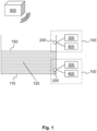
- Fig. 1 shows a schematic overview of an example system or an example system with two impedance limit switches 100.
- the impedance limit switch 100 has a measuring probe 200, a frequency generator 300 with variable frequency and an analysis unit 400.
- the frequency generator 300 and the analysis unit 400 are connected to the measuring probe 200, so that the frequency generator 300 can apply a frequency to the measuring probe 200 and the analysis unit 400 can measure and/or determine the impedance of the measuring probe 200 at a specific frequency.
- Each of the measuring probes 200 is arranged within the container 110.
- the container 110 contains filling material 120, up to a filling level 150. In the example shown, one of the measuring probes 200 is arranged above the filling level 150, the other of the measuring probes 200 below.
- the impedance limit switch 100 is influenced by a jammer 500, so that the impedance measured by the analysis unit 400 is superimposed on the frequency of the jammer 500 and, in particular, may be incorrect.
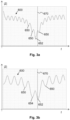
- Fig. 2 an undisturbed impedance curve 600 is shown.
- the frequency f is plotted on the x-axis and the magnitude of the impedance
- the impedance curve 600 was determined, for example, by means of the lower impedance limit switch 100 Fig. 1 measured at numerous support points 640 (not shown).
- the global minimum 652 of the measured impedance can be clearly seen.
- an impedance limit line 670 is indicated, which indicates the limit frequency for covering the measuring probe 200 with the filling material 120. If the global minimum 652 lies to the left of the impedance boundary line 670, the measuring probe 200 is covered with the filling material 120, which is the case here, for example.
- the superposition by the jammer 500 also leads to a high ripple in the impedance curve 600 and at first glance differs only slightly from the measurement of Fig. 3a .
- the random distribution of the local minima 650 results in the measured global minimum 652 being shifted by a significant amount and therefore lying to the right of the impedance boundary line 670.
- the impedance limit switch 100 incorrectly determining the coverage state, namely the incorrect result “measuring probe 200 not covered”.
- the so-called second global minimum 654 of the measured impedance which is used by an embodiment of the impedance limit switch 100 to determine the quality criterion.
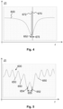
- Fig. 4 shows an example of determining a frequency safety margin 675.
- the frequency safety margin 675 is measured during a functional test of the impedance limit switch 100.
- the limit frequency for the impedance in air 670 and the limit frequency for the impedance in the filling material 672 are measured.
- the distance between these two resonance frequencies or - taking measurement qualities into account - the two limit frequencies is referred to as the frequency safety distance 675,
- Fig. 5 shows an example of determining a frequency error margin 655 during a measurement.
- the global minimum 652 and the second global minimum 654 of the measured impedance are selected from the local minima 650. These have the lowest or second lowest impedance of a measurement.
- the quality criterion for the measurement can be determined in some embodiments. This is for example in Fig. 3b is not met, so this measurement cannot be used to determine coverage. In such a case, the impedance limit switch 100 initiates a further measurement.
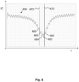
- the result can be an impedance curve 600, as shown in Fig. 6 is shown. It can be seen that the global minima 650 are closer together. This can be caused by several factors, in particular by an increased number of second support points 642.
- the frequency safety margin 675 is greater than 0.5 times the frequency error margin 655, so that this measurement can be used. This shows that the global minimum 652 lies to the left of the cutoff frequency 670 and therefore correctly indicates coverage with the filling material.
- the invention also includes a method for determining the coverage of an impedance limit switch with a filling material, by means of the impedance limit switch, under the influence of a jammer, as described in Fig. 7 is shown.
- the procedure has the following steps: In step 701, the measuring probe is subjected to a predefined first frequency and the frequency is changed continuously or stepwise, within a predefined first time period, up to a predefined second frequency.
- step 702 a measurement of the impedance of the measurement probe is determined, at each first reference point of the continuously or stepwise changed frequency.
- step 703 a large number of local minima of the impedance of the measuring probe are determined from the measured values of the impedance at the first support points.
- a quality criterion is determined from a plurality of measured values. If the quality criterion for the measurement is not met, then, in step 705, the measuring probe is subjected to the predefined first frequency and the frequency is changed continuously or stepwise, within a predefined second time period that differs from the first time period. The frequency is up to the predefined second frequency. A measured value of the impedance of the measuring probe is determined at every second support point of the continuously or stepwise changed frequency, the number of the second support points differing from the number of the first support points. If the quality criterion for the measurement is met, it is determined, in step 706, whether a global minimum, from the plurality of local minima, is above or below the cutoff frequency for the impedance in air. The coverage can be determined from this.
Description
Die Erfindung betrifft Vorrichtungen und Verfahren zur Füllstandmessung oder Grenzstandbestimmung, insbesondere einen Impedanzgrenzschalter, der auf einem elektrischen Resonanzkreis basiert, weiterhin ein Verfahren zur Grenzstandbestimmung, eine Verwendung, ein Programmelement und ein computerlesbares Medium.The invention relates to devices and methods for level measurement or limit level determination, in particular an impedance limit switch that is based on an electrical resonance circuit, furthermore a method for limit level determination, a use, a program element and a computer-readable medium.
Zur Füllstandmessung, beispielsweise in einem Behälter, werden verschiedene Arten von Sensorsystemen eingesetzt. Eine Familie dieser Sensorsysteme sind sog. Grenzstandmelder. Diese werden insbesondere eingesetzt, um einen bestimmten Pegel eines Füllguts, z.B. in einem Behälter, anzuzeigen, d.h. ob etwa eine vordefinierte obere oder untere Grenze des Füllstands in dem Behälter erreicht wurde. Mit den Signalen von dem Grenzstandmelder werden beispielsweise Befülleinrichtungen oder Entleereinrichtungen, wie z.B. Förderbänder oder Pumpen, gesteuert. Eine Fehlfunktion eines Grenzstandmelders kann daher erheblichen Schaden verursachen.Various types of sensor systems are used to measure fill levels, for example in a container. One family of these sensor systems are so-called point level detectors. These are used in particular to indicate a specific level of a filling material, for example in a container, i.e. whether a predefined upper or lower limit of the fill level in the container has been reached. The signals from the level detector are used to control filling devices or emptying devices, such as conveyor belts or pumps. A malfunction of a point level detector can therefore cause significant damage.
Ein Typus von Grenzstandmeldem sind sog. Impedanzgrenzschalter. Diese weisen eine Elektronikeinheit und eine Messsonde auf. Zwischen Messelektrode und Bezugselektrode bildet sich eine Messkapazität aus, welche mit einer diskreten Induktivität einen Serienschwingkreis bildet. Befindet sich ein Füllgut im Bereich der Messsonde, insbesondere wenn der Impedanzgrenzschalter von dem Füllgut bedeckt wird, so beeinflusst dies die Gesamtkapazität und/oder Gesamtinduktivität des Schwingkreises und ändert damit die Resonanzfrequenz des Schwingkreises.One type of limit level detectors are so-called impedance limit switches. These have an electronic unit and a measuring probe. Between measuring electrode and reference electrode A measuring capacitance is formed, which forms a series resonant circuit with a discrete inductance. If there is a filling material in the area of the measuring probe, especially if the impedance limit switch is covered by the filling material, this influences the total capacity and/or total inductance of the resonant circuit and thus changes the resonant frequency of the resonant circuit.
Zur Messung der Resonanzfrequenz wird der Schwingkreis durch einen Signalgenerator mit veränderlicher Frequenz angeregt. Die Impedanz des Schwingkreises ändert sich dabei über die Frequenz. Dies kann beispielsweise durch eine Kurve veranschaulicht werden, bei welcher der Betrag der Impedanz (y-Achse) über der Frequenz (x-Achse) angetragen ist. Diese Kurve wird gelegentlich "Impedanzkurve" genannt. Die Kurve zeigt ein Minimum bei der Resonanzfrequenz des Schwingkreises. Weil bei Bedeckung des Impedanzgrenzschalters mit dem Füllgut die Resonanzfrequenz des Schwingkreises - und damit das Minimum der Impedanz - bei einer anderen Frequenz liegt als ohne Bedeckung, kann mit diesem Messprinzip eine klare Unterscheidung vorgenommen werden, ob der Impedanzgrenzschalter von dem Füllgut bedeckt ist oder nicht, d.h. ob die vordefinierte obere oder untere Grenze des Füllstands erreicht wurde.To measure the resonance frequency, the resonant circuit is excited by a signal generator with a variable frequency. The impedance of the resonant circuit changes depending on the frequency. This can be illustrated, for example, by a curve in which the magnitude of the impedance (y-axis) is plotted against the frequency (x-axis). This curve is sometimes called the “impedance curve.” The curve shows a minimum at the resonant frequency of the resonant circuit. Because when the impedance limit switch is covered with the filling material, the resonance frequency of the resonant circuit - and thus the minimum of the impedance - is at a different frequency than when it is not covered, a clear distinction can be made with this measuring principle as to whether the impedance limit switch is covered by the filling material or not. i.e. whether the predefined upper or lower limit of the fill level has been reached.
Die
Beim Betrieb einer Anlage mit einem Impedanzgrenzschalter können aber Störeinstrahlungen auftreten, die von einem Störsender verursacht werden. Derartige Störsender können z.B.However, when operating a system with an impedance limit switch, interference caused by a jammer can occur. Such jammers can e.g
Förderbänder oder Pumpen sein, die von dem Impedanzgrenzschalter gesteuert werden und die in vielen Fällen in der Nähe des Impedanzgrenzschalters angeordnet sind. Durch diese Störeinstrahlungen wird die Resonanzkurve des Schwingkreises durch das Störsignal überlagert. Dadurch kann, abhängig von Intensität und Frequenz des Störsignals, das gemessene Minimum der Impedanz verschoben werden und, als Folge dieser Verschiebung, fälschlicherweise ein Schaltzustand "Bedeckung" oder ein Schaltzustand "Nicht-Bedeckung" bestimmt werden.Be conveyor belts or pumps that are controlled by the impedance limit switch and which are in many cases arranged near the impedance limit switch. Due to this interference, the resonance curve of the resonant circuit is superimposed by the interference signal. As a result, depending on the intensity and frequency of the interference signal, the measured minimum impedance can be shifted and, as a result of this shift, a “coverage” switching state or a “non-coverage” switching state can be incorrectly determined.
Die Aufgabe der Erfindung ist es, die Nachteile des Standes der Technik wenigstens teilweise zu überwinden, insbesondere trotz Störeinstrahlungen den korrekten Schaltzustand des Impedanzgrenzschalters mit hoher Wahrscheinlichkeit zu erkennen.The object of the invention is to at least partially overcome the disadvantages of the prior art to overcome, especially to detect the correct switching state of the impedance limit switch with a high degree of probability despite interference.
Diese Aufgabe wird durch den Gegenstand der unabhängigen Patentansprüche gelöst. Weiterbildungen der Erfindung ergeben sich aus den Unteransprüchen und der folgenden Beschreibung.This task is solved by the subject matter of the independent patent claims. Further developments of the invention result from the subclaims and the following description.
Ein Impedanzgrenzschalter zur Bestimmung der Bedeckung des Impedanzgrenzschalters mit einem Füllgut weist dabei eine Messsonde auf, welche zumindest teilweise innerhalb eines Behälters angeordnet ist. Der Behälter kann ein Gefäß von beliebiger Form sein. Der Behälter kann auch ein Gerinne, beispielsweise ein Bach- oder Flussbett sein. Der Impedanzgrenzschalter kann an einer beliebigen Stelle innerhalb des Behälters angeordnet sein.An impedance limit switch for determining the coverage of the impedance limit switch with a filling material has a measuring probe which is at least partially arranged within a container. The container can be a vessel of any shape. The container can also be a channel, for example a stream or river bed. The impedance limit switch can be located anywhere within the container.
Die Messsonde weist dabei mindestens eine Messelektrode, eine Bezugselektrode und eine vordefinierte Induktivität auf. Der Schwingkreis ist ein Serienschwingkreis, bei dem die Induktivität in Reihe geschalten ist mit einem Kondensator, der die Messelektrode und die Bezugselektrode aufweist. Dieser Kondensator wird gelegentlich als "Messkapazität" bezeichnet. Diese Messkapazität ist innerhalb der Messsonde so angeordnet, dass diese sich in der Nähe der Oberfläche der Messsonde befindet, damit die Messsonde eine möglichst hohe Empfindlichkeit für die Beeinflussung durch die kapazitiven und/oder induktiven Eigenschaften des Füllguts aufweist. Das Füllgut kann z.B. eine Flüssigkeit oder Schüttgut sein.The measuring probe has at least one measuring electrode, a reference electrode and a predefined inductance. The resonant circuit is a series resonant circuit in which the inductance is connected in series with a capacitor that has the measuring electrode and the reference electrode. This capacitor is sometimes referred to as the "measuring capacitance". This measuring capacitance is arranged within the measuring probe so that it is located near the surface of the measuring probe so that the measuring probe has the highest possible sensitivity to the influence of the capacitive and / or inductive properties of the filling material. The filling material can be, for example, a liquid or bulk material.
Ferner weist der Impedanzgrenzschalter einen Frequenzgenerator mit variabler Frequenz auf, welcher dazu eingerichtet ist, die Messsonde mit einer Frequenz zu beaufschlagen. Es handelt sich dabei um einen sog. Wobbelgenerator, der auch unter den Bezeichnungen Wobbler, Wobbelsender oder "sweep generator" bekannt ist. Ein Wobbelgenerator variiert die erzeugte Frequenz innerhalb einer vordefinierten Zeitspanne zwischen zwei einstellbaren Endwerten, d.h. zwischen einer vordefinierten ersten Frequenz und einer vordefinierten zweiten Frequenz.Furthermore, the impedance limit switch has a frequency generator with a variable frequency, which is set up to apply a frequency to the measuring probe. This is a so-called wobble generator, which is also known as wobbler, wobble transmitter or “sweep generator”. A wobble generator varies the generated frequency within a predefined period of time between two adjustable end values, ie between a predefined first frequency and a predefined second frequency.
Der Frequenzgenerator ist mit der Messsonde verbunden und dazu eingerichtet, die Messsonde mit einer von diesem erzeugten Frequenz zu beaufschlagen. In einer Ausführungsform der Erfindung kann der Frequenzgenerator eine spannungsgesteuerte Oszillatorschaltung sein, ein sog. VCO (Voltage Controlled Oscillator).The frequency generator is connected to the measuring probe and is set up to apply a frequency generated by the measuring probe to the measuring probe. In one embodiment of the invention, the frequency generator can be a voltage-controlled oscillator circuit, a so-called VCO (Voltage Controlled Oscillator).
Weiterhin weist der Impedanzgrenzschalter eine Analyseeinheit auf. Diese ist dazu eingerichtet, die Impedanz der Messsonde bei einer bestimmten Frequenz, bzw. innerhalb des vom Frequenzgenerator erzeugen Frequenzbereichs, zu messen. Dabei kann ein Störsender die durch die Analyseeinheit gemessenen Impedanzwerte beeinflussen, da die Frequenzen, die der Störsender erzeugt, die Messwerte der Analyseeinheit überlagern können.The impedance limit switch also has an analysis unit. This is set up to measure the impedance of the measuring probe at a specific frequency or within the frequency range generated by the frequency generator. A jammer can influence the impedance values measured by the analysis unit, since the frequencies that the jammer generates can superimpose the measured values of the analysis unit.
Der Impedanzgrenzschalter ist eingerichtet, zur Messung der Bedeckung die folgenden Schritte durchzuführen:
- Beaufschlagen der Messsonde mit einer vordefinierten ersten Frequenz, gewissermaßen mit der Startfrequenz des Wobbelgenerators und kontinuierliches oder schrittweises Verändern der Frequenz, innerhalb einer vordefinierten Zeitspanne, bis zu einer vordefinierten zweiten Frequenz. Dabei hängt es von der Art des Wobbelgenerators ab, ob die Frequenz kontinuierlich oder schrittweise verändert wird. Es ist bei vielen Wobbelgeneratoren einstellbar, ob der vordefinierte Frequenzbereich von einer niedrigeren Frequenz bis zu einer höheren Frequenz durchlaufen wird oder umgekehrt. Beides ist im Sinne dieser Erfindung.
- Bestimmung eines Messwerts der Impedanz der Messsonde an jeder ersten Stützstelle der kontinuierlich oder schrittweise veränderten Frequenz.
- Bestimmung einer Vielzahl von lokalen Minima der gemessenen Impedanz der Messsonde, aus den Messwerten der Impedanz an den ersten Stützstellen. Die gemessene Impedanz entspricht nur bei einer störungsfreien Messung der tatsächlichen Impedanz der Messsonde. Wenn hingegen ein Störsender die Messwerte beeinflusst, dann können diese Messwerte von der tatsächlichen Impedanz der Messsonde - sogar erheblich - abweichen. Weil in der Regel nicht bekannt ist, bei welchen Frequenzen der Störsender wie stark sendet, kann durch die Überlagerung mit den Frequenzen der Störsender ein falsches globales Minimum der Impedanz gemessen werden, beispielsweise ein globales Minimum, das an einer anderen Frequenz liegt als das tatsächliche globale Minimum. Dies ist insbesondere deshalb kritisch, weil das globale Minimum der Impedanz ein Indikator für die Bestimmung der Bedeckung des Impedanzgrenzschalters mit dem Füllgut ist.
- Bestimmung eines Qualitätskriteriums aus einer Mehrzahl von Messwerten. Dieses Qualitätskriterium kann auf Basis von Messwerten aus dem letzten Messvorgang bestimmt werden, aus einem der vorangegangenen Messvorgänge, oder auch auf Basis einer oder mehrerer Messwerte, die beispielsweise bei der Kalibrierung des Systems gemessen wurden. Das Qualitätskriterium wird als ein Indiz dafür genommen, ob die gemessenen Werte, und insbesondere die Vielzahl von lokalen Minima, überhaupt eine belastbare Basis bieten für die Entscheidung, ob der Impedanzgrenzschalter mit dem Füllgut bedeckt ist oder nicht. Das Qualitätskriterium liefert also mindestens eine diesbezügliche Ja/Nein-Entscheidung; es kann darüberhinaus aber auch ein Maß für die Qualität der Messung liefern.
- Wenn das Qualitätskriterium für die Messung nicht erfüllt ist, dann veranlasst der Impedanzgrenzschalter das Beaufschlagen der Messsonde mit der vordefinierten ersten Frequenz und kontinuierliches oder schrittweises Verändern der Frequenz, innerhalb einer vordefinierten zweiten Zeitspanne, die sich von der ersten Zeitspanne unterscheidet, bis zu der vordefinierten zweiten Frequenz, und Bestimmung eines Messwerts der Impedanz der Messsonde an jeder zweiten Stützstelle der kontinuierlich oder schrittweise veränderten Frequenz, wobei die Anzahl der zweiten Stützstellen sich von der Anzahl der ersten Stützstellen unterscheidet. Es wird also eine "Nachmessung" veranlasst, mit geänderten Werten für die Zeitspanne und die Anzahl der Stützstellen.
- Applying a predefined first frequency to the measuring probe, in a sense the starting frequency of the wobble generator, and continuously or stepwise changing the frequency, within a predefined period of time, up to a predefined second frequency. It depends on the type of wobble generator whether the frequency is changed continuously or gradually. With many wobble generators it is possible to set whether the predefined frequency range is run through from a lower frequency to a higher frequency or vice versa. Both are within the meaning of this invention.
- Determination of a measured value of the impedance of the measuring probe at each first reference point of the continuously or stepwise changed frequency.
- Determination of a large number of local minima of the measured impedance of the measuring probe, from the measured values of the impedance at the first support points. The measured impedance only corresponds to the actual impedance of the measuring probe if the measurement is interference-free. However, if a jammer influences the measured values, then these measured values can deviate from the actual impedance of the measuring probe - even significantly. Because it is generally not known at which frequencies the jammer transmits and how strongly, a false global minimum of the impedance can be measured by superimposing the frequencies of the jammers, for example a global minimum that is at a different frequency than the actual global one Minimum. This is particularly critical because the global minimum impedance is an indicator for determining the coverage of the impedance limit switch with the filling material.
- Determination of a quality criterion from a plurality of measured values. This quality criterion can be determined on the basis of measured values from the last measuring process, from one of the previous measuring processes, or on the basis of one or more measured values that were measured, for example, during the calibration of the system. The quality criterion is taken as an indication of whether the measured values, and in particular the large number of local minima, provide a reliable basis for deciding whether the impedance limit switch is covered with the filling material or not. The quality criterion therefore provides at least a yes/no decision in this regard; However, it can also provide a measure of the quality of the measurement.
- If the quality criterion for the measurement is not met, then the impedance limit switch causes the measuring probe to be subjected to the predefined first frequency and the frequency to be changed continuously or step by step within a predefined second period of time, which is different from the first period of time distinguishes, up to the predefined second frequency, and determining a measured value of the impedance of the measuring probe at every second support point of the continuously or stepwise changed frequency, the number of second support points differing from the number of first support points. A “re-measurement” is therefore initiated, with changed values for the time period and the number of support points.
Die erste und zweite Frequenz bleibt dabei in vielen Ausführungsformen unverändert. In anderen Ausführungsformen werden die erste und zweite Frequenz verändert, beispielsweise kann ein engerer Frequenzbereich um die die Resonanzfrequenz ausgewählt werden, oder auch ein breiterer Frequenzbereich, um die Auswirkung des Störsenders stärker durch das Qualitätskriterium zu berücksichtigen.The first and second frequencies remain unchanged in many embodiments. In other embodiments, the first and second frequencies are changed, for example a narrower frequency range around which the resonance frequency can be selected, or even a wider frequency range in order to take the impact of the jammer into greater account through the quality criterion.
In einigen Ausführungsformen ist die vordefinierte zweite Zeitspanne länger als die erste Zeitspanne. Dies kann einhergehen mit einer Erhöhung der Anzahl der Stützstellen, so dass die Anzahl der zweiten Stützstellen höher, insbesondere deutlich höher, ist als die Anzahl der ersten Stützstellen.In some embodiments, the predefined second time period is longer than the first time period. This can be accompanied by an increase in the number of support points, so that the number of second support points is higher, in particular significantly higher, than the number of first support points.
Dieses Vorgehen kann dazu führen, dass mehrere Nachmessungen stattfinden und/oder die vordefinierte zweite Zeitspanne und/oder die Anzahl der zweiten Stützstellen mehrfach variiert werden müssen, um das Qualitätskriterium zu erfüllen. In einer Ausführungsform kann die vordefinierte zweite Zeitspanne und/oder die Anzahl der zweiten Stützstellen, die zu einem positiven Qualitätskriterium führten, in einem Speicher vermerkt sein, so dass die Nachmessungen bevorzugt mit diesen Werten durchgeführt werden.
- Wenn das Qualitätskriterium für die Messung erfüllt ist, dann veranlasst der Impedanzgrenzschalter die Bestimmung, ob ein globales Minimum, aus der Vielzahl von lokalen Minima, über oder unter der Grenzfrequenz für die Impedanz in Luft liegt, woraus sich die Bedeckung bestimmen lässt.
- If the quality criterion for the measurement is met, then the impedance limit switch determines whether a global minimum, from the multitude of local minima, is above or below the limit frequency for the impedance in air, from which the coverage can be determined.
Wenn also die gemessenen Werte eine belastbare Basis bieten für die Entscheidung, ob der Impedanzgrenzschalter mit dem Füllgut bedeckt ist, dann wird das gemessene globale Minimum als relevante Resonanzfrequenz angesehen und auf dieser Basis die Bedeckung bestimmt.If the measured values provide a reliable basis for deciding whether the impedance limit switch is covered with the filling material, then the measured global minimum is viewed as the relevant resonance frequency and the coverage is determined on this basis.
Erfindungsgemäß beinhaltet das Qualitätskriterium für die Messung:
- Die Bestimmung eines Frequenzsicherheitsabstandes aus der Differenz der Grenzfrequenz für die Impedanz in Luft von der Grenzfrequenz für die Impedanz in dem Füllgut. Diese Bestimmung kann beispielsweise bei der Kalibrierung oder dem Qualitätstest des Impedanzgrenzschalters durchgeführt werden. In einer Ausführungsform werden die Grenzfrequenzen für die Impedanz in Luft und für die Impedanz von verschiedenen Arten von Füllgut in einem Speicher hinterlegt, wahlweise für jeden einzelnen Impedanzgrenzschalter oder für eine bestimmte Serie.
- Bestimmung eines Frequenzfehlerabstandes aus der Differenz des globalen Minimums und eines zweit-globalen Minimums der Impedanz. Dabei ist das zweit-globale Minimum diejenige Frequenz, d.h. dasjenige gemessene lokale Minimum, das - neben dem globalen Minimum - den zweitniedrigsten Wert für die Impedanz hat.
- Bestimmung, ob der Frequenzsicherheitsabstand größer ist als der k-fache Frequenzfehlerabstand, wobei der Faktor k einen Wert zwischen 0,5 und 0,7, insbesondere den Wert 0,5, hat.
- The determination of a frequency safety margin from the difference of the cutoff frequency for the impedance in air from the cutoff frequency for the impedance in the filling material. This determination can be made, for example, during calibration or quality testing of the impedance limit switch. In one embodiment, the limit frequencies for the impedance in air and for the impedance of different types of filling material are stored in a memory, either for each individual impedance limit switch or for a specific series.
- Determination of a frequency error distance from the difference of the global minimum and a second global minimum of the impedance. The second global minimum is the frequency, ie the measured local minimum, which - next to the global minimum - has the second lowest value for the impedance.
- Determination of whether the frequency safety margin is greater than k times the frequency error margin, whereby the factor k has a value between 0.5 and 0.7, in particular the value 0.5.
In einigen Ausführungsformen sind die vordefinierte zweite Zeitspanne und die Anzahl der zweiten Stützstellen Funktionen des Frequenzfehlerabstandes und des Frequenzsicherheitsabstandes.In some embodiments, the predefined second time period and the number of second sampling points are functions of the frequency error margin and the frequency safety margin.
In einigen Ausführungsformen erfolgt, wenn das Qualitätskriterium für die Messung erfüllt ist, als weiterer Schritt: Beaufschlagen der Messsonde mit der vordefinierten ersten Frequenz und kontinuierliches oder schrittweises Verändern der Frequenz, innerhalb einer vordefinierten dritten Zeitspanne, die sich von der ersten und der zweiten Zeitspanne unterscheidet, bis zu der vordefinierten zweiten Frequenz; und Bestimmung einer der Impedanz der Messsonde, aus den Messwerten der Impedanz an den dritten Stützstellen, deren Anzahl sich von der Anzahl der ersten und der zweiten Stützstellen unterscheidet. Dabei sind die vordefinierte dritte Zeitspanne und die Anzahl der dritten Stützstellen Funktionen des Frequenzfehlerabstandes und des Frequenzsicherheitsabstandes. In einigen Ausführungsformen ist die vordefinierte dritte Zeitspanne kürzer als die erste Zeitspanne. Dies führt vorteilhafterweise zu einer weiteren Reduzierung des Energieverbrauchs des Impedanzgrenzschalters.In some embodiments, if the quality criterion for the measurement is met, a further step takes place: applying the predefined first frequency to the measuring probe and changing the frequency continuously or stepwise within a predefined third time period, which differs from the first and the second time period , up to the predefined second frequency; and determining one of the impedances of the measuring probe from the measured values of the impedance at the third support points, the number of which differs from the number of the first and second support points. The predefined third time period and the number of third support points are functions of the frequency error distance and the frequency safety distance. In some embodiments, the predefined third time period is shorter than the first time period. This advantageously leads to a further reduction in the energy consumption of the impedance limit switch.
Die beschriebenen Bestimmungen der Bedeckung sind auch mit einem Parallelschwingkreis möglich. Dabei liegt bei der Resonanzfrequenz das Maximum der Impedanz. Sämtliche Angaben, die sich in den vorangegangenen Absätzen auf lokale und globale Minima beziehen, müssen bei Verwendung eines Parallelschwingkreises angepasst, d.h. statt dessen auf lokale und globale Maxima bezogen werden.The coverage provisions described are also possible with a parallel resonant circuit. The maximum impedance lies at the resonance frequency. All information that refers to local and global minima in the previous paragraphs must be adjusted when using a parallel resonant circuit, i.e. instead refer to local and global maxima.
In einer Ausführungsform der Erfindung beträgt die Anzahl der Stützstellen zwischen 100 und 10000, bevorzugt zwischen 200 und 1000, besonders bevorzugt zwischen 300 und 500. Die Stützstellen können äquidistant beabstandet sein. Die Stützstellen können aber auch logarithmisch äquidistant oder mit einer anderen Funktion bewertet äquidistant sein.In one embodiment of the invention, the number of support points is between 100 and 10,000, preferably between 200 and 1000, particularly preferably between 300 and 500. The support points can be equidistantly spaced. The support points can also be logarithmically equidistant or evaluated with another function.
In einer Ausführungsform der Erfindung ist die vordefinierte erste Frequenz die untere Frequenz und liegt in einem Bereich zwischen 10 MHz und 500 MHz, beispielsweise in einem Bereich zwischen 50 MHz und 250 MHz, insbesondere in einem Bereich zwischen 90 MHz und 120 MHz. Die vordefinierte zweite Frequenz ist dabei die obere Frequenz und liegt in einem Bereich zwischen 20 MHz und 1000 MHz, beispielsweise in einem Bereich zwischen 100 und 500 MHz, insbesondere in einem Bereich zwischen 170 MHz und 250 MHz. Dabei findet die Messung von der unteren zur oberen Frequenz statt. Diese gewählten Frequenzbereiche weisen den Vorteil auf, dass damit die Messsonde relativ klein gehalten werden kann.In one embodiment of the invention, the predefined first frequency is the lower frequency and lies in a range between 10 MHz and 500 MHz, for example in a range between 50 MHz and 250 MHz, in particular in a range between 90 MHz and 120 MHz. The predefined second frequency is the upper frequency and lies in a range between 20 MHz and 1000 MHz, for example in a range between 100 and 500 MHz, especially in a range between 170 MHz and 250 MHz. The measurement takes place from the lower to the upper frequency. These selected frequency ranges have the advantage that the measuring probe can be kept relatively small.
In einer Ausführungsform der Erfindung ist die vordefinierte erste Frequenz die obere Frequenz und die vordefinierte zweite Frequenz ist die untere Frequenz. Dabei findet die Messung von der oberen zur unteren Frequenz statt.In one embodiment of the invention, the predefined first frequency is the upper frequency and the predefined second frequency is the lower frequency. The measurement takes place from the upper to the lower frequency.
In einer Ausführungsform beträgt die vordefinierte erste Zeitspanne und die vordefinierte zweite Zeitspanne zwischen 1 ms und 1000 ms, bevorzugt zwischen 5 ms und 200 ms. Die längeren Zeitspannen beanspruchen die Stromversorgung länger, was bei akku- oder batteriebetriebenen Geräten eine Rolle spielen kann. In manchen Ausführungsformen können die längeren Zeitspannen zu einer präziseren Bestimmung der lokalen Minima führen.In one embodiment, the predefined first time period and the predefined second time period are between 1 ms and 1000 ms, preferably between 5 ms and 200 ms. The longer periods of time place longer demands on the power supply, which can be a factor in cordless or battery-powered devices. In some embodiments, the longer time periods may result in a more precise determination of the local minima.
In einer Ausführungsform weist die Messsonde eine Messelektrode und eine Bezugselektrode auf, so dass sich zwischen der Messelektrode und der Bezugselektrode eine Messimpedanz, oder eine Messkapazität und einen Messwiderstand, ausbildet, welche mit einer diskreten Induktivität eine Serienresonanz erzeugt. In einer anderen Ausführungsform ist die Messkapazität mit der Induktivität parallel geschaltet. Damit erreicht der Betrag der Impedanz bei der Resonanzfrequenz ein Maximum. Die Bestimmung der Bedeckung des Impedanzgrenzschalters verwendet dabei die lokalen und globalen Maxima, statt der oben erläuterten lokalen und globalen Minima.In one embodiment, the measuring probe has a measuring electrode and a reference electrode, so that a measuring impedance, or a measuring capacitance and a measuring resistance, is formed between the measuring electrode and the reference electrode, which generates a series resonance with a discrete inductance. In another embodiment, the measuring capacitance is connected in parallel with the inductance. This means that the magnitude of the impedance reaches a maximum at the resonance frequency. The determination of the coverage of the impedance limit switch uses the local and global maxima, instead of the local and global minima explained above.
In einer Ausführungsform sind die Messsonde, der Frequenzgenerator und die Analyseeinheit, insbesondere zusammen mit einer Stromversorgung, in einem Gehäuse und/oder auf einer Platine angeordnet. Diese Anordnung hat den Vorteil, dass damit die Beeinflussung durch den Störsender minimiert wird.In one embodiment, the measuring probe, the frequency generator and the analysis unit are arranged, in particular together with a power supply, in a housing and/or on a circuit board. This arrangement has the advantage that the influence of the jammer is minimized.
In einer Ausführungsform sind in dem Gehäuse und/oder auf der Platine weiterhin eine drahtgebundene oder eine drahtlose Kommunikationseinheit angeordnet. Dies eignet sich insbesondere für Anlagen, die mehrere dezentrale Messpunkte aufweisen. Dementsprechend können für die Kommunikation z.B. Feldbusse oder drahtlose Kommunikationsprotokolle verwendet werden.In one embodiment, a wired or wireless communication unit is further arranged in the housing and/or on the circuit board. This is particularly suitable for systems that have several decentralized measuring points. Accordingly, fieldbuses or wireless communication protocols, for example, can be used for communication.
In einigen Ausführungsformen ist der Störsender eine EMV-Immission. Diese können insbesondere von einem Elektromotor oder einem Ottomotor verursacht werden. Diese Motoren können beispielsweise Teile von Förderbändern, von Förderpumpen oder von Rührwerken sein. In manchen Ausführungsformen wird die Störung durch eine EMV-Immission nach mindestens einer der Prüfgrundlagen IEC 61000-6-2, IEC 61000-4-20, IEC 61326-1, IEC 61326-2-3, NE 21 und/oder E10 bestimmt. Weiterhin kann die Störfestigkeit des Impedanzgrenzschalters nach mindestens einer von diesen Normen geprüft werden.In some embodiments, the jammer is an EMC immission. These can be caused in particular by an electric motor or a gasoline engine. These motors can, for example, be parts of conveyor belts, feed pumps or agitators. In some embodiments, the interference is determined by EMC immission according to at least one of the test principles IEC 61000-6-2, IEC 61000-4-20, IEC 61326-1, IEC 61326-2-3, NE 21 and/or E10. Furthermore, the interference immunity of the impedance limit switch can be tested according to at least one of these standards.
Der Impedanzgrenzschalter oder das hier beschriebene Verfahren wird zur Bestimmung des Füllstandes von Flüssigkeiten, insbesondere von Wasser, Saft, Milch, Alkohole, Öle, Farbe, Ketchup, Honig, bevorzugt mit einem DK-Wert zwischen 1,5 und 81, oder von Schüttgut, insbesondere von granulierten oder pulverförmigen Schüttgütern, z.B. Mehl, Sand, Kaffeepulver, Kunststoffgranulat, bevorzugt mit einem DK-Wert zwischen 1,5 und 81, verwendet.The impedance limit switch or the method described here is used to determine the level of liquids, in particular water, juice, milk, alcohols, oils, paint, ketchup, honey, preferably with a DK value between 1.5 and 81, or of bulk goods, used in particular for granulated or powdered bulk materials, e.g. flour, sand, coffee powder, plastic granules, preferably with a DK value between 1.5 and 81.
Gemäß einer Ausführungsform beinhaltet der Impedanzgrenzschalter ein Programmelement, welches, wenn es auf der Prozessoreinheit eines Impedanzgrenzschalters ausgeführt wird, den Impedanzgrenzschalter anweist, das hier beschriebene Verfahren durchzuführen. Die Analyseeinheit kann Teil der Prozessoreinheit sein.According to one embodiment, the impedance limit switch includes a program element which, when executed on the processor unit of an impedance limit switch, instructs the impedance limit switch to carry out the method described herein. The analysis unit can be part of the processor unit.
Der Impedanzgrenzschalter kann weiterhin ein computerlesbares Medium beinhalten, auf dem das hier beschriebene Programmelement gespeichert ist.The impedance limit switch may further include a computer-readable medium on which the program element described herein is stored.
-
Fig. 1 zeigt eine schematische Übersicht über ein System oder eine Anlage mit zwei Impedanzgrenzschaltern;Fig. 1 shows a schematic overview of a system or installation with two impedance limit switches; -
Fig. 2 zeigt eine Darstellung einer ungestörten Impedanzkurve, die mittels eines Impedanzgrenzschalters gemessen wurde;Fig. 2 shows a representation of an undisturbed impedance curve that was measured using an impedance limit switch; -
Fig. 3a zeigt eine gestörte Impedanzkurve, bei der das gemessene globale Minimum um einen geringen Betrag verschoben wurde;Fig. 3a shows a perturbed impedance curve where the measured global minimum has been shifted by a small amount; -
Fig. 3b zeigt eine gestörte Impedanzkurve, bei der das gemessene globale Minimum um einen erheblichen Betrag verschoben wurde;Fig. 3b shows a perturbed impedance curve where the measured global minimum has been shifted by a significant amount; -
Fig. 4 zeigt ein Beispiel für einen Frequenzsicherheitsabstand am Beispiel einer ungestörten Impedanzkurve;Fig. 4 shows an example of a frequency safety margin using an undisturbed impedance curve as an example; -
Fig. 5 zeigt ein Beispiel für einen Frequenzfehlerabstand am Beispiel einer gestörten Impedanzkurve;Fig. 5 shows an example of a frequency error distance using the example of a disturbed impedance curve; -
Fig. 6 zeigt ein Beispiel für eine gestörte Impedanzkurve, bei der die Anzahl der Stützstellen erhöht wurde;Fig. 6 shows an example of a disturbed impedance curve in which the number of support points has been increased; -
Fig. 7 zeigt ein Verfahren zur Bestimmung der Bedeckung eines Impedanzgrenzschalters mit einem Füllgut.Fig. 7 shows a method for determining the coverage of an impedance limit switch with a filling material.
Die Darstellungen in den Figuren sind schematisch und nicht maßstäblich.The representations in the figures are schematic and not to scale.
Werden in der folgenden Figurenbeschreibung in verschiedenen Figuren die gleichen Bezugszeichen verwendet, so bezeichnen diese gleiche oder ähnliche Elemente.If the same reference numbers are used in different figures in the following description of the figures, they indicate the same or similar elements.
In
Bei realen Messungen kann aber eine Überlagerung mit den Frequenzen des Störsenders 500 stattfinden. Beispiele für daraus resultierende Diagramme sind in
Bei einer Messung, wie sie in
Bei einer Messung, wie sie in
Nach der Messung des Frequenzsicherheitsabstands 675 (siehe
Die Erfindung umfasst auch ein Verfahren zur Bestimmung der Bedeckung eines Impedanzgrenzschalters mit einem Füllgut, mittels des Impedanzgrenzschalters, unter Einwirkung eines Störsenders, wie es in
In Schritt 701 erfolgt das Beaufschlagen der Messsonde mit einer vordefinierten ersten Frequenz und kontinuierliches oder schrittweises Verändern der Frequenz, innerhalb einer vordefinierten ersten Zeitspanne, bis zu einer vordefinierten zweiten Frequenz.The invention also includes a method for determining the coverage of an impedance limit switch with a filling material, by means of the impedance limit switch, under the influence of a jammer, as described in
In
In Schritt 702 wird ein Messwert der Impedanz der Messsonde bestimmt, und zwar an jeder ersten Stützstelle der kontinuierlich oder schrittweise veränderten Frequenz.In
In Schritt 703 erfolgt die Bestimmung einer Vielzahl von lokalen Minima der Impedanz der Messsonde, aus den Messwerten der Impedanz an den ersten Stützstellen.In
In Schritt 704 erfolgt die Bestimmung eines Qualitätskriteriums aus einer Mehrzahl von Messwerten. Ist das Qualitätskriterium für die Messung nicht erfüllt, dann wird, in Schritt 705, die Messsonde mit der vordefinierten ersten Frequenz beaufschlagt und die Frequenz wird kontinuierlich oder schrittweise verändert, und zwar innerhalb einer vordefinierten zweiten Zeitspanne, die sich von der ersten Zeitspanne unterscheidet. Die Frequenz wird bis zu der vordefinierten zweiten Frequenz. Dabei erfolgt die Bestimmung eines Messwerts der Impedanz der Messsonde an jeder zweiten Stützstelle der kontinuierlich oder schrittweise veränderten Frequenz, wobei die Anzahl der zweiten Stützstellen sich von der Anzahl der ersten Stützstellen unterscheidet. Wenn das Qualitätskriterium für die Messung erfüllt ist, wird, in Schritt 706, bestimmt, ob ein globales Minimum, aus der Vielzahl von lokalen Minima, über oder unter der Grenzfrequenz für die Impedanz in Luft liegt. Daraus lässt sich die Bedeckung bestimmen.In
Ergänzend sei darauf hingewiesen, dass "umfassend" und "aufweisend" keine anderen Elemente oder Schritte ausschließt und die unbestimmten Artikel "eine" oder "ein" keine Vielzahl ausschließen. Ferner sei darauf hingewiesen, dass Merkmale oder Schritte, die mit Verweis auf eines der obigen Ausführungsbeispiele beschrieben worden sind, auch in Kombination mit anderen Merkmalen oder Schritten anderer oben beschriebener Ausführungsbeispiele verwendet werden können. Bezugszeichen in den Ansprüchen sind nicht als Einschränkungen anzusehen.In addition, it should be noted that "comprising" and "having" do not exclude other elements or steps and the indefinite articles "a" or "an" do not exclude a plurality. Furthermore, it should be noted that features or steps that have been described with reference to one of the above-described exemplary embodiments can also be used in combination with other features or steps of other above-described embodiments. Reference symbols in the claims are not to be regarded as limitations.
- 100100
- ImpedanzgrenzschalterImpedance limit switch
- 110110
- Behältercontainer
- 120120
- Füllgutfilling material
- 150150
- Füllstandlevel
- 200200
- Messsondemeasuring probe
- 300300
- FrequenzgeneratorFrequency generator
- 400400
- AnalyseeinheitUnit of analysis
- 450450
- ProzessoreinheitProcessor unit
- 500500
- Störsenderjammer
- 600600
- ImpedanzkurveImpedance curve
- 610610
- vordefinierte erste Frequenzpredefined first frequency
- 620620
- vordefinierte zweite Frequenzpredefined second frequency
- 631631
- vordefinierte erste Zeitspannepredefined first time period
- 632632
- vordefinierte zweite Zeitspannepredefined second time period
- 633633
- vordefinierte dritte Zeitspannepredefined third time period
- 641641
- erste Stützstellefirst support point
- 642642
- zweite Stützstellesecond support point
- 643643
- dritte Stützstellethird support point
- 650650
- lokales Minimum der gemessenen Impedanzlocal minimum of the measured impedance
- 652652
- globales Minimum der gemessenen Impedanzglobal minimum of the measured impedance
- 654654
- zweit-globales Minimum der gemessenen Impedanzsecond global minimum of the measured impedance
- 655655
- FrequenzfehlerabstandFrequency error distance
- 670670
- Grenzfrequenz für die Impedanz in LuftLimit frequency for the impedance in air
- 672672
- Grenzfrequenz für die Impedanz in dem FüllgutLimit frequency for the impedance in the filling material
- 675675
- Frequenzsicherheitsabstand Luft und FlüssigkeitFrequency safety distance air and liquid
- 701 bis 706701 to 706
- Schritte des VerfahrensSteps of the procedure
Claims (15)
- An impedance limit switch (100) for determining a coverage of the impedance limit switch (100) with a filling material (120), comprising:a measuring probe (200),a variable frequency generator (300) configured to apply a frequency to the measuring probe (200), andan analysis unit (400) configured to determine the impedance of the measuring probe (200) at a certain frequency,wherein the impedance measured by the analysis unit (400) can be influenced by a jamming transmitter (500),wherein the impedance limit switch (100) is arranged to perform the following steps:- applying a predefined first frequency (610) to the measuring probe (200) and continuously or stepwise changing the frequency, within a predefined first time period (631), up to a predefined second frequency (620);- determining a measured value of the impedance of the measuring probe (200) at each first supporting point (641) of the continuously or stepwise changed frequency;- determining a plurality of local minima (650) of the impedance of the measuring probe (200), from the measured values of the impedance at the first support points (641);- determining a quality criterion from a plurality of measured values, wherein the quality criterion for the measurement includes:- determining a frequency safety margin (675) from the difference of the cut-off frequency for the impedance in air (670) from the cut-off frequency for the impedance in the medium (672);- determining a frequency error margin (655) from the difference of the global minimum (652) and a second-global minimum (654) of the impedance;- determining if the frequency safety margin (675) is greater than the k-fold frequency error margin (655), wherein the factor k has a value between 0.5 and 0.7;- if the quality criterion for the measurement is not met, especially because of the interfering transmitter (500),applying the predefined first frequency (610) to the measuring probe (200) and continuously or stepwise changing the frequency, within a predefined second time period (632) different from the first time period (631), up to the predefined second frequency (620), anddetermining a measured value of the impedance of the measuring probe (200) at every second supporting point (642) of the continuously or stepwise changed frequency, wherein the number of second supporting points (642) differs from the number of first supporting points (641);- if the quality criterion for the measurement is met,determining whether a global minimum (652), out of the plurality of local minima (650), is above or below the cutoff frequency for impedance in air (670),from which the coverage can be determined.
- The impedance limit switch (100) according to claim 1,
wherein the factor k has the value 0.5. - The impedance limit switch (100) according to claim 1 or 2,
wherein the predefined second time period (632) and the number of second interpolation points (642) are functions of the frequency error margin (655) and the frequency security margin (675). - The impedance limit switch (100) according to any one of the preceding claims,wherein, if the quality criterion for the measurement is met, as a further step:- applying the predefined first frequency (610) to the measurement probe (200) and continuously or incrementally changing the frequency, within a predefined third time period (632) different from the first (631) and second (632) time periods, up to the predefined second frequency (620); and determining one of the impedance of the measuring probe (200), from the measured values of the impedance at the third supporting points (643), the number of which is different from the number of the first (641) and the second (642) supporting points;wherein the predefined third time period (633) and the number of third interpolation points (643) are functions of the frequency error margin (655) and the frequency security margin (675).
- The impedance limit switch (100) according to any one of the preceding claims,
wherein the number of supporting points (641, 642) is between 100 and 10 000, in particular between 200 and 1000, for example between 300 and 500. - The impedance limit switch (100) according to any one of the preceding claims,wherein the predefined first frequency (610) is in a range between 10 MHz and 500 MHz, for example in a range between 50 MHz and 250 MHz, and in particular in a range between 90 MHz and 120 MHz, andthe predefined second frequency (620) is in a range between 20 MHz and 1000 MHz, for example in a range between 100 MHz and 500 MHz, and in particular in a range between 170 and 250 MHz.
- The impedance limit switch (100) according to any one of the preceding claims,wherein the predefined first frequency (610) corresponds to the second frequency of claim 4, andthe predefined second frequency (620) corresponds to the first frequency of claim 4.
- The impedance limit switch (100) according to any one of the preceding claims,
wherein the predefined first time period (631) and the predefined second time period (632) are between 1 ms and 1000 ms, preferably between 5 ms and 200 ms. - Method for determining the coverage of an impedance limit switch (100) with a filling material (120), by means of the impedance limit switch (100), influenced by a jamming transmitter (500), according to any one of the preceding claims, comprising the steps:- applying a predefined first frequency (610) to the measuring probe (200) and continuously or stepwise changing the frequency, within a predefined first time period (631), up to a predefined second frequency (620);- determining a measured value of the impedance of the measuring probe (200) at each first supporting point (641) of the continuously or stepwise changed frequency;- determining a plurality of local minima (650) of the impedance of the measuring probe (200), from the measured values of the impedance at the first support points (641);- determining a quality criterion from a plurality of measured values, wherein the quality criterion for the measurement includes:- determining a frequency safety margin (675) from the difference of the cut-off frequency for the impedance in air (670) from the cut-off frequency for the impedance in the medium (672);- determining a frequency error margin (655) from the difference of the global minimum (652) and a second-global minimum (654) of the impedance;- determining if the frequency error margin (655) is less than k times the frequency safety margin (675), wherein the factor k has a value between 0.3 and 0.7;- if the quality criterion for the measurement is not met,applying the predefined first frequency (610) to the measuring probe (200) and continuously or stepwise changing the frequency, within a predefined second time period (632) different from the first time period (631), up to the predefined second frequency (620), anddetermining a measured value of the impedance of the measuring probe (200) at every second supporting point (642) of the continuously or stepwise changed frequency, wherein the number of second supporting points (642) differs from the number of first supporting points (641);- if the quality criterion for the measurement is met,determining whether a global minimum (652), out of the plurality of local minima (650), is above or below the cutoff frequency for impedance in air (670),from which the coverage can be determined.
- The method of claim 9,
wherein the factor k has the value 0.5. - The method according to claim 9 or 10,
wherein the predefined second time period (632) and the number of second interpolation points (642) are functions of the frequency error margin (655) and the frequency security margin (675). - The method according to claim 9 to 11,wherein, if the quality criterion for the measurement is met, as a further step:- applying the predefined first frequency (610) to the measurement probe (200) and continuously or incrementally changing the frequency, within a predefined third time period (632) different from the first (631) and second (632) time periods, up to the predefined second frequency (620); and- determining one of the impedance of the measuring probe (200), from the measured values of the impedance at the third supporting points (643), the number of which is different from the number of the first (641) and the second (642) supporting points;wherein the predefined third time period (633) and the number of third interpolation points (643) are functions of the frequency error margin (655) and the frequency security margin (675).
- Use of an impedance limit switch (100) according to any one of claims 1 to 8 or a method according to claims 13 to 15 for measuring the coverage of the impedance limit switch (100).with liquids, particularly with a DK value between 1.5 and 81, e.g. water, juice, milk, alcohols, oils, paint, ketchup, honey, orwith bulk material, in particular granulated or powdery bulk material, particularly with a DK value between 1.5 and 81, e.g. flour, sand, coffee powder, plastic granules.
- A program element which, when executed on the processing unit (450) of an impedance limit switch (100), instructs the impedance limit switch (100) to perform the method of claims 9 to 11.
- A computer-readable medium on which is stored a program element according to claim 14.
Priority Applications (1)
| Application Number | Priority Date | Filing Date | Title |
|---|---|---|---|
| EP18171297.7A EP3567349B1 (en) | 2018-05-08 | 2018-05-08 | Impedance limit switches with adaptation of excitation |
Applications Claiming Priority (1)
| Application Number | Priority Date | Filing Date | Title |
|---|---|---|---|
| EP18171297.7A EP3567349B1 (en) | 2018-05-08 | 2018-05-08 | Impedance limit switches with adaptation of excitation |
Publications (2)
| Publication Number | Publication Date |
|---|---|
| EP3567349A1 EP3567349A1 (en) | 2019-11-13 |
| EP3567349B1 true EP3567349B1 (en) | 2023-10-18 |
Family
ID=62143025
Family Applications (1)
| Application Number | Title | Priority Date | Filing Date |
|---|---|---|---|
| EP18171297.7A Active EP3567349B1 (en) | 2018-05-08 | 2018-05-08 | Impedance limit switches with adaptation of excitation |
Country Status (1)
| Country | Link |
|---|---|
| EP (1) | EP3567349B1 (en) |
Family Cites Families (3)
| Publication number | Priority date | Publication date | Assignee | Title |
|---|---|---|---|---|
| DE102009060742A1 (en) * | 2009-12-30 | 2011-07-07 | NEGELE Messtechnik GmbH, 87743 | Device for detecting a water level |
| EP3153829B1 (en) * | 2015-10-07 | 2020-12-02 | VEGA Grieshaber KG | Method and device for limit state determination |
| EP3312571B1 (en) * | 2016-10-20 | 2021-10-13 | VEGA Grieshaber KG | Impedance type medium limit switch comprising an additional shield electrode |
-
2018
- 2018-05-08 EP EP18171297.7A patent/EP3567349B1/en active Active
Also Published As
| Publication number | Publication date |
|---|---|
| EP3567349A1 (en) | 2019-11-13 |
Similar Documents
| Publication | Publication Date | Title |
|---|---|---|
| EP2668474B1 (en) | Device and method for capacitively measuring a fill level | |
| EP2360486B1 (en) | Method for calibrating a partial discharge measurement device | |
| WO2014131639A1 (en) | Method and apparatus for monitoring a predefined filling level of a medium in a container | |
| EP3312571B1 (en) | Impedance type medium limit switch comprising an additional shield electrode | |
| EP2899563A1 (en) | Method and device for detecting a malfunction of an ultrasonic transducer by evaluating an impedance envelope | |
| EP3308110A1 (en) | Method for testing the functionality of a radar-based fill state measuring device | |
| WO2013034293A1 (en) | Method for checking an antenna coil | |
| WO2004051248A1 (en) | Method and device for determining the water content and conductivity in the ground and in bulk materials | |
| EP3153829B1 (en) | Method and device for limit state determination | |
| EP2634921B1 (en) | Proximity sensor and method for determining the approach to electrically conductive body | |
| EP3118591B1 (en) | Fill level measurement device | |
| DE102017100269A1 (en) | Method for detecting a fault condition on an FMCW-based level gauge | |
| EP3652508A1 (en) | Capacitive measuring method, and filling level measuring device | |
| EP3567349B1 (en) | Impedance limit switches with adaptation of excitation | |
| DE10063557B4 (en) | Method and device for measuring water levels | |
| DE102018207171B4 (en) | Impedance limit switch, based on electrical resonance formation, with optimized data analysis to improve immunity to interference | |
| WO2017220293A1 (en) | Capacitive limit level switch | |
| WO2016041726A1 (en) | Device and method for monitoring a process variable of a medium | |
| EP3631381A1 (en) | Method for process monitoring | |
| WO2001061286A2 (en) | Device for determining the level of a medium in a container | |
| EP3605029B1 (en) | Impedance sensor and method for determining the switching state of an impedance sensor | |
| DE102016210982B4 (en) | Capacitive limit switch | |
| EP3746753A1 (en) | Method for detecting potential faulty states on an fmcw-based filling level measuring apparatus | |
| EP3521778B1 (en) | Impedance sensor and method for its operation | |
| EP3605028A1 (en) | Method for determining a switching condition of an impedance sensor and impedance sensor |
Legal Events
| Date | Code | Title | Description |
|---|---|---|---|
| PUAI | Public reference made under article 153(3) epc to a published international application that has entered the european phase |
Free format text: ORIGINAL CODE: 0009012 |
|
| STAA | Information on the status of an ep patent application or granted ep patent |
Free format text: STATUS: REQUEST FOR EXAMINATION WAS MADE |
|
| 17P | Request for examination filed |
Effective date: 20190410 |
|
| AK | Designated contracting states |
Kind code of ref document: A1 Designated state(s): AL AT BE BG CH CY CZ DE DK EE ES FI FR GB GR HR HU IE IS IT LI LT LU LV MC MK MT NL NO PL PT RO RS SE SI SK SM TR |
|
| AX | Request for extension of the european patent |
Extension state: BA ME |
|
| STAA | Information on the status of an ep patent application or granted ep patent |
Free format text: STATUS: EXAMINATION IS IN PROGRESS |
|
| 17Q | First examination report despatched |
Effective date: 20220204 |
|
| GRAP | Despatch of communication of intention to grant a patent |
Free format text: ORIGINAL CODE: EPIDOSNIGR1 |
|
| RIC1 | Information provided on ipc code assigned before grant |
Ipc: G01F 23/263 20220101ALI20230425BHEP Ipc: G01F 23/26 20060101AFI20230425BHEP |
|
| STAA | Information on the status of an ep patent application or granted ep patent |
Free format text: STATUS: GRANT OF PATENT IS INTENDED |
|
| INTG | Intention to grant announced |
Effective date: 20230601 |
|
| P01 | Opt-out of the competence of the unified patent court (upc) registered |
Effective date: 20230719 |
|
| GRAS | Grant fee paid |
Free format text: ORIGINAL CODE: EPIDOSNIGR3 |
|
| GRAA | (expected) grant |
Free format text: ORIGINAL CODE: 0009210 |
|
| STAA | Information on the status of an ep patent application or granted ep patent |
Free format text: STATUS: THE PATENT HAS BEEN GRANTED |
|
| AK | Designated contracting states |
Kind code of ref document: B1 Designated state(s): AL AT BE BG CH CY CZ DE DK EE ES FI FR GB GR HR HU IE IS IT LI LT LU LV MC MK MT NL NO PL PT RO RS SE SI SK SM TR |
|
| RAP3 | Party data changed (applicant data changed or rights of an application transferred) |
Owner name: VEGA GRIESHABER KG |
|
| REG | Reference to a national code |
Ref country code: GB Ref legal event code: FG4D Free format text: NOT ENGLISH |
|
| REG | Reference to a national code |
Ref country code: CH Ref legal event code: EP |
|
| REG | Reference to a national code |
Ref country code: IE Ref legal event code: FG4D Free format text: LANGUAGE OF EP DOCUMENT: GERMAN |
|
| REG | Reference to a national code |
Ref country code: DE Ref legal event code: R096 Ref document number: 502018013464 Country of ref document: DE |
|
| REG | Reference to a national code |
Ref country code: LT Ref legal event code: MG9D |
|
| REG | Reference to a national code |
Ref country code: NL Ref legal event code: MP Effective date: 20231018 |
|
| PG25 | Lapsed in a contracting state [announced via postgrant information from national office to epo] |
Ref country code: NL Free format text: LAPSE BECAUSE OF FAILURE TO SUBMIT A TRANSLATION OF THE DESCRIPTION OR TO PAY THE FEE WITHIN THE PRESCRIBED TIME-LIMIT Effective date: 20231018 |
|
| PG25 | Lapsed in a contracting state [announced via postgrant information from national office to epo] |
Ref country code: GR Free format text: LAPSE BECAUSE OF FAILURE TO SUBMIT A TRANSLATION OF THE DESCRIPTION OR TO PAY THE FEE WITHIN THE PRESCRIBED TIME-LIMIT Effective date: 20240119 |
|
| PG25 | Lapsed in a contracting state [announced via postgrant information from national office to epo] |
Ref country code: IS Free format text: LAPSE BECAUSE OF FAILURE TO SUBMIT A TRANSLATION OF THE DESCRIPTION OR TO PAY THE FEE WITHIN THE PRESCRIBED TIME-LIMIT Effective date: 20240218 |
|
| PG25 | Lapsed in a contracting state [announced via postgrant information from national office to epo] |
Ref country code: LT Free format text: LAPSE BECAUSE OF FAILURE TO SUBMIT A TRANSLATION OF THE DESCRIPTION OR TO PAY THE FEE WITHIN THE PRESCRIBED TIME-LIMIT Effective date: 20231018 |