EP3567332A1 - Swirling feed tube for heat exchanger - Google Patents
Swirling feed tube for heat exchanger Download PDFInfo
- Publication number
- EP3567332A1 EP3567332A1 EP19173305.4A EP19173305A EP3567332A1 EP 3567332 A1 EP3567332 A1 EP 3567332A1 EP 19173305 A EP19173305 A EP 19173305A EP 3567332 A1 EP3567332 A1 EP 3567332A1
- Authority
- EP
- European Patent Office
- Prior art keywords
- inlet
- walls
- heat exchanger
- flow
- recited
- Prior art date
- Legal status (The legal status is an assumption and is not a legal conclusion. Google has not performed a legal analysis and makes no representation as to the accuracy of the status listed.)
- Granted
Links
Images




Classifications
-
- F—MECHANICAL ENGINEERING; LIGHTING; HEATING; WEAPONS; BLASTING
- F28—HEAT EXCHANGE IN GENERAL
- F28F—DETAILS OF HEAT-EXCHANGE AND HEAT-TRANSFER APPARATUS, OF GENERAL APPLICATION
- F28F9/00—Casings; Header boxes; Auxiliary supports for elements; Auxiliary members within casings
- F28F9/02—Header boxes; End plates
- F28F9/026—Header boxes; End plates with static flow control means, e.g. with means for uniformly distributing heat exchange media into conduits
- F28F9/0265—Header boxes; End plates with static flow control means, e.g. with means for uniformly distributing heat exchange media into conduits by using guiding means or impingement means inside the header box
- F28F9/0268—Header boxes; End plates with static flow control means, e.g. with means for uniformly distributing heat exchange media into conduits by using guiding means or impingement means inside the header box in the form of multiple deflectors for channeling the heat exchange medium
-
- F—MECHANICAL ENGINEERING; LIGHTING; HEATING; WEAPONS; BLASTING
- F28—HEAT EXCHANGE IN GENERAL
- F28F—DETAILS OF HEAT-EXCHANGE AND HEAT-TRANSFER APPARATUS, OF GENERAL APPLICATION
- F28F9/00—Casings; Header boxes; Auxiliary supports for elements; Auxiliary members within casings
- F28F9/02—Header boxes; End plates
- F28F9/026—Header boxes; End plates with static flow control means, e.g. with means for uniformly distributing heat exchange media into conduits
- F28F9/0265—Header boxes; End plates with static flow control means, e.g. with means for uniformly distributing heat exchange media into conduits by using guiding means or impingement means inside the header box
-
- F—MECHANICAL ENGINEERING; LIGHTING; HEATING; WEAPONS; BLASTING
- F28—HEAT EXCHANGE IN GENERAL
- F28F—DETAILS OF HEAT-EXCHANGE AND HEAT-TRANSFER APPARATUS, OF GENERAL APPLICATION
- F28F13/00—Arrangements for modifying heat-transfer, e.g. increasing, decreasing
- F28F13/06—Arrangements for modifying heat-transfer, e.g. increasing, decreasing by affecting the pattern of flow of the heat-exchange media
-
- F—MECHANICAL ENGINEERING; LIGHTING; HEATING; WEAPONS; BLASTING
- F28—HEAT EXCHANGE IN GENERAL
- F28F—DETAILS OF HEAT-EXCHANGE AND HEAT-TRANSFER APPARATUS, OF GENERAL APPLICATION
- F28F13/00—Arrangements for modifying heat-transfer, e.g. increasing, decreasing
- F28F13/06—Arrangements for modifying heat-transfer, e.g. increasing, decreasing by affecting the pattern of flow of the heat-exchange media
- F28F13/12—Arrangements for modifying heat-transfer, e.g. increasing, decreasing by affecting the pattern of flow of the heat-exchange media by creating turbulence, e.g. by stirring, by increasing the force of circulation
-
- F—MECHANICAL ENGINEERING; LIGHTING; HEATING; WEAPONS; BLASTING
- F28—HEAT EXCHANGE IN GENERAL
- F28F—DETAILS OF HEAT-EXCHANGE AND HEAT-TRANSFER APPARATUS, OF GENERAL APPLICATION
- F28F9/00—Casings; Header boxes; Auxiliary supports for elements; Auxiliary members within casings
- F28F9/02—Header boxes; End plates
- F28F9/026—Header boxes; End plates with static flow control means, e.g. with means for uniformly distributing heat exchange media into conduits
- F28F9/0263—Header boxes; End plates with static flow control means, e.g. with means for uniformly distributing heat exchange media into conduits by varying the geometry or cross-section of header box
-
- F—MECHANICAL ENGINEERING; LIGHTING; HEATING; WEAPONS; BLASTING
- F28—HEAT EXCHANGE IN GENERAL
- F28F—DETAILS OF HEAT-EXCHANGE AND HEAT-TRANSFER APPARATUS, OF GENERAL APPLICATION
- F28F9/00—Casings; Header boxes; Auxiliary supports for elements; Auxiliary members within casings
- F28F9/02—Header boxes; End plates
- F28F9/026—Header boxes; End plates with static flow control means, e.g. with means for uniformly distributing heat exchange media into conduits
- F28F9/027—Header boxes; End plates with static flow control means, e.g. with means for uniformly distributing heat exchange media into conduits in the form of distribution pipes
- F28F9/0273—Header boxes; End plates with static flow control means, e.g. with means for uniformly distributing heat exchange media into conduits in the form of distribution pipes with multiple holes
-
- F—MECHANICAL ENGINEERING; LIGHTING; HEATING; WEAPONS; BLASTING
- F28—HEAT EXCHANGE IN GENERAL
- F28F—DETAILS OF HEAT-EXCHANGE AND HEAT-TRANSFER APPARATUS, OF GENERAL APPLICATION
- F28F9/00—Casings; Header boxes; Auxiliary supports for elements; Auxiliary members within casings
- F28F9/02—Header boxes; End plates
- F28F2009/0285—Other particular headers or end plates
- F28F2009/029—Other particular headers or end plates with increasing or decreasing cross-section, e.g. having conical shape
Definitions
- a heat exchanger includes adjacent flow paths that transfer heat from a hot flow to a cooling flow.
- the flow paths are defined by a combination of plates and fins that are arranged to transfer heat from one flow to another flow.
- Thermal gradients present in the sheet material create stresses that can be very high in certain locations. Increasing temperatures and pressures can result in stresses on the structure that can exceed material and assembly capabilities.
- Turbine engine manufactures utilize heat exchangers throughout the engine to cool and condition airflow for cooling and other operational needs. Improvements to turbine engines have enabled increases in operational temperatures and pressures. The increases in temperatures and pressures improve engine efficiency but also increase demands on all engine components including heat exchangers.
- Turbine engine manufacturers continue to seek further improvements to engine performance including improvements to thermal, transfer and propulsive efficiencies.
- a heat exchanger assembly in a featured embodiment, includes an inlet manifold defining an expanding area in a direction of flow; and an inlet in flow communication with the inlet manifold, the inlet including a wall for inducing a rotational inertia to flow entering the inlet manifold.
- the inlet comprises a constant cross-sectional area over an inlet length prior to the inlet manifold.
- the inlet comprises a pipe and the wall comprises a plurality of walls spirally arranged within the inlet length.
- the pipe is round and includes an inner surface and the plurality of walls are disposed transverse to the inner surface.
- the plurality of walls include a height and the height is less than a width of the pipe.
- the plurality of walls extend across a width of the pipe and define separate channels.
- the plurality of walls are continuous for the entire inlet length.
- the plurality of walls are intermittently arranged for at least a portion of the inlet length.
- a density of walls is uniform for the entire inlet length.
- a density of walls varies within the inlet length.
- a distance between the plurality of walls in a direction parallel to a longitudinal axis and an angle of the walls relative to the longitudinal axis and a swirl induced into the inlet flow is determined by a combination of the distance between the plurality of walls and the angle.
- At least one of the distance between the plurality of walls and angle of the plurality of walls varies over a length of the inlet.
- a heat exchanger assembly including an inlet manifold defining an increasing flow area.
- a plate fin heat exchanger plate includes a first end in flow communication with the inlet manifold and including a plurality of inlet openings arranged across an inlet width.
- An inlet communicating flow to the inlet manifold includes a means for inducing a spiral flow for spreading flow through the inlet manifold across the inlet width.
- the inlet includes a uniform cross-sectional flow area over an inlet length.
- inlet comprises a pipe and the means for introducing a spiral inertial comprises a plurality of walls spirally arranged and extending from an interior surface of the pipe within the inlet length.
- the plurality of walls include a height from the inner surface and the height that is less than a width of the pipe.
- the plurality of walls extend define separate channels within the inlet.
- a method of assembling a heat exchanger assembly includes forming an inlet manifold to include an expanding flow area, attaching the inlet manifold to a plate fin heat exchanger that includes a plurality of openings disposed across an inlet width. Forming an inlet to include a constant flow area and a spiral flow inducing means; and attaching the inlet to the inlet manifold for spreading flow entering the inlet manifold across inlet width.
- the spiral flow inducing means comprises a plurality walls extending inward from an inner surface that are arranged in a spiral along an inlet length.
- At least one of a distance between the plurality of walls in a direction common with a longitudinal axis of the inlet and an angle of the plurality of walls relative to the longitudinal axis is defined to induce a defined swirl component into the flow entering the inlet manifold.
- an example heat exchanger 10 includes an inlet manifold 12 that feeds hot airflow 18 to a plate fin heat exchanger 14.
- the plate fin heat exchanger 14 includes an inlet end 32 attached to the inlet manifold 12 and an outlet end 34 attached to the outlet manifold 16.
- the hot flow 18 is communicated through an opening 30 of an inlet pipe 22 to the inlet manifold 12 and thereby to the plate fin heat exchanger 14.
- a cooling airflow 20 flows over the plate fin heat exchanger 14 and accepts heat from the hot flow 18.
- Outgoing hot flow 18 through the exhaust outlet manifold 16 is of a cooler temperature than the hot flow 18 into the inlet manifold 12.
- the plate fin heat exchanger 14 includes a plurality of internal passages schematically shown at 26 and an outer surface including a plurality of fins 24. Each of the passages 26 is in communication with the inlet end 32 that includes a plurality of openings 36. The openings 36 are disposed across an inlet width 28 that is in communication with the inlet manifold 12.
- a typical inlet manifold 112 receives flow from an inlet pipe 122.
- the flow projects into the manifold 112 and does not expand uniformly toward outer areas schematically indicated at 125. Instead, the flow concentrates within a center region 116 of the manifold and the corresponding center passages 126 within a heat exchanger 114.
- the non-uniform distribution of flow in to the heat exchanger 114 reduces heat transfer efficiency.
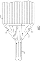
- the disclosed example inlet manifold 12 includes a first area 40 near the inlet pipe 22 and a second area 42 near the inlet end 32.
- the first area 40 is much smaller than the second area 42.
- the inlet manifold 12 includes an expanding cross-sectional flow area in a direction towards the plate fin heat exchanger 14 inlet end 32.
- the rapidly increasing flow area within the inlet manifold 12 can cause distribution problems of flow entering from the inlet pipe 22. Flow entering from the inlet pipe 22 will proceed towards the center most passages of the plate fin heat exchanger 14 potentially leaving gaps of lower flow to areas indicated schematically at 25 near the inlet end 32.
- the example inlet pipe 22 includes a means for distributing flow entering the inlet manifold 12 across the entire width 28 of the inlet end 32.
- the means for distributing flow includes a plurality of walls 38 on the inner surface of the inlet pipe 22 to induce a spiral flow to the incoming flow to uniformly distribute flow along the inlet width 28.
- the example inlet pipe 22 includes an inlet length 44 with a substantially constant flow area.
- the walls 38 are provided within the inlet length 44, but may also extend throughout the entire inlet pipe 22.
- the walls 38 may also be provided only within the inlet length 44.
- the inlet length 44 is a length that is predetermined to provide sufficient turns to induce the desired spiral component to incoming hot flow 18.
- the walls 38 are twisted within the inlet pipe 22 to induce a spiral flow component inlet manifold 12.
- the induced spiral flow components drive flow towards the extremes of the inlet width 28 schematically indicated at 25.
- the mixing and distributions provided by the swirling flows provide a more uniform distribution of the hot flow 18 into the plate fin heat exchanger 14.
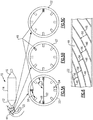
- sections of the inlet pipe 22 are illustrated for the inlet length 44 and show the twist of one wall section 46 at different positions about the circumference of the inlet pipe 22.
- the wall section 46 spirally winds along the inner surface of the inlet pipe 22.
- Each of the walls 46 extends a height 54 from the internal surface 48.
- the height 54 is much less than a width 52 of the inlet pipe 22.
- the width 52 in the disclosed example inlet 22 is a diameter of the inlet 22.
- the example inlet 22 is a circular pipe including a circular inner surface 48.
- Each of the walls 46 extend the height 54 towards the center portion of the inlet 22.
- each of the walls 46 are disposed transversally at an angle 50 normal to the inner surface 48. It should be appreciated that the walls 46 may be disposed at an angle other than normal to provide a desired flow component into the inlet manifold 12.
- circumferential spacing between the walls 46 define channels 56 for the flow 18.
- the spiral round channels 56 induce a spiral swirling component into the flow that carries forward through the inlet manifold 12.
- the spiral component to the inlet hot flow 18 drives portions of the flow toward the sides of the inlet end 32 to more uniformly distribute flow into the heat exchanger plate 14.
- an example inlet 22' includes the example walls 46 are spaced apart to define channels 58.
- the walls 46 are spaced the distance 58 to provide a defined density along the inlet length 44.
- the density of walls 46 within the inlet length 44 is provided to define a desired amount of swirl into the inlet flow.
- FIG. 8 another example inlet 60 is disclosed includes spacing 64 that is greater than the spacing 58 described in the previous embodiment.
- the increased spacing 64 illustrates a different density of walls 62 within the inlet 22 to enable tuning specific flow parameters designed to spread incoming flow across the passages 36.
- FIG. 9 another example inlet 68 is disclosed and includes a plurality of walls 70 that are intermittent and includes spaces 72 therebetween.
- the spaces 72 demonstrate that walls 70 need not be uniform or constant throughout the entire inlet length 44.
- the inlet pipe 68 includes intermittent walls 70 that provide the desired inducement of swirl into the incoming flow.
- density is also be changed by varying an angle 90 of the walls 92.
- the angle 90 defines the length that an individual wall 92 needs to rotate 360 degrees about the interior wall of the inlet pipe.
- the space 88 between the walls 92 is a function of the angle 90 and the number of walls 92 within a length 95 of the inlet cross section.
- the changing angle 90 enables tailoring a swirl rate of airflow through the inlet.
- the swirl rate is modified as function of the angle 90 and the number of walls 92 within the length 95 of the inlet. The steeper the angle 90, the more turns for the same length 95.
- increasing or reducing the number of walls 92 also can be tailored to provide a desired swirl in the incoming flow.
- An inlet 82 shown in Figure 10a includes walls 92 that are a distance 88a apart and disposed at an angle 90a relative to a longitudinal axis A.
- the angle 90a and number of walls 92 for the length 95 defines a density that is tailored to induce a predefined swirl into the flow exiting the inlet 82.
- the example angle in one disclosed embodiment, is less than 90 degrees and more than 45 degrees.
- the distance 88a is a function of the angle 90a of the walls 92 in the defined length 95.
- FIG. 10b Another inlet 84 shown in Figure 10b includes walls 92 that disposed at an angle 90b combined with a number of walls 92 that provides a spacing 88b that is less than the spacing 88a shown in Figure 10a .
- the angle 90a remains the same, but increasing the number of walls 92 decrease in the spacing 88b to provide increased swirl for the same length 95.
- a further inlet 86 shown in Figure 10c includes an angle 90b that is not as steep as the previous angle 90a.
- the number of walls 92 is reduced and therefore the distance 88c is greater than either that shown in Figures 10a and 10b .
- the different angle 90b with a reduced number of walls 92 provides a larger spacing 88c to induce the desired defined swirl in the inlet flow.
- the swirl provided by the walls 92 of the inlet 86 can have any number of variation of the walls 92 and angles 90 to provide different spacings 88 to induce different swirl in flows exiting the inlet tube.
- FIG. 11a, 11b, and 11c another example inlet 76 is disclosed and includes a plurality walls 78 defining a corresponding plurality of closed passages 80 that spirally wind along the inlet length 44.
- the plurality of separate passages 80 induce swirl components into the incoming airflow to uniformly spread and distribute airflow along the inlet end 32 of the plate fin heat exchanger 14.
- the disclosed inlet pipe induces flow characteristics that aid in more uniformly distributing the hot airflow throughout the passages of the heat exchanger.
Landscapes
- Engineering & Computer Science (AREA)
- Physics & Mathematics (AREA)
- Thermal Sciences (AREA)
- Mechanical Engineering (AREA)
- General Engineering & Computer Science (AREA)
- Geometry (AREA)
- Heat-Exchange Devices With Radiators And Conduit Assemblies (AREA)
Abstract
Description
- A heat exchanger includes adjacent flow paths that transfer heat from a hot flow to a cooling flow. The flow paths are defined by a combination of plates and fins that are arranged to transfer heat from one flow to another flow. Thermal gradients present in the sheet material create stresses that can be very high in certain locations. Increasing temperatures and pressures can result in stresses on the structure that can exceed material and assembly capabilities.
- Turbine engine manufactures utilize heat exchangers throughout the engine to cool and condition airflow for cooling and other operational needs. Improvements to turbine engines have enabled increases in operational temperatures and pressures. The increases in temperatures and pressures improve engine efficiency but also increase demands on all engine components including heat exchangers.
- Turbine engine manufacturers continue to seek further improvements to engine performance including improvements to thermal, transfer and propulsive efficiencies.
- In a featured embodiment, a heat exchanger assembly includes an inlet manifold defining an expanding area in a direction of flow; and an inlet in flow communication with the inlet manifold, the inlet including a wall for inducing a rotational inertia to flow entering the inlet manifold.
- In another embodiment according to the previous embodiment, the inlet comprises a constant cross-sectional area over an inlet length prior to the inlet manifold.
- In another embodiment according to any of the previous embodiments, the inlet comprises a pipe and the wall comprises a plurality of walls spirally arranged within the inlet length.
- In another embodiment according to any of the previous embodiments, the pipe is round and includes an inner surface and the plurality of walls are disposed transverse to the inner surface.
- In another embodiment according to any of the previous embodiments, the plurality of walls include a height and the height is less than a width of the pipe.
- In another embodiment according to any of the previous embodiments, the plurality of walls extend across a width of the pipe and define separate channels.
- In another embodiment according to any of the previous embodiments, the plurality of walls are continuous for the entire inlet length.
- In another embodiment according to any of the previous embodiments, the plurality of walls are intermittently arranged for at least a portion of the inlet length.
- In another embodiment according to any of the previous embodiments, a density of walls is uniform for the entire inlet length.
- In another embodiment according to any of the previous embodiments, a density of walls varies within the inlet length.
- In another embodiment according to any of the previous embodiments, a distance between the plurality of walls in a direction parallel to a longitudinal axis and an angle of the walls relative to the longitudinal axis and a swirl induced into the inlet flow is determined by a combination of the distance between the plurality of walls and the angle.
- In another embodiment according to any of the previous embodiments, at least one of the distance between the plurality of walls and angle of the plurality of walls varies over a length of the inlet.
- In another featured embodiment, a heat exchanger assembly including an inlet manifold defining an increasing flow area. A plate fin heat exchanger plate includes a first end in flow communication with the inlet manifold and including a plurality of inlet openings arranged across an inlet width. An inlet communicating flow to the inlet manifold includes a means for inducing a spiral flow for spreading flow through the inlet manifold across the inlet width.
- In another embodiment according to the previous embodiment, the inlet includes a uniform cross-sectional flow area over an inlet length.
- In another embodiment according to any of the previous embodiments, inlet comprises a pipe and the means for introducing a spiral inertial comprises a plurality of walls spirally arranged and extending from an interior surface of the pipe within the inlet length.
- In another embodiment according to any of the previous embodiments, the plurality of walls include a height from the inner surface and the height that is less than a width of the pipe.
- In another embodiment according to any of the previous embodiments, the plurality of walls extend define separate channels within the inlet.
- In another featured embodiment, a method of assembling a heat exchanger assembly includes forming an inlet manifold to include an expanding flow area, attaching the inlet manifold to a plate fin heat exchanger that includes a plurality of openings disposed across an inlet width. Forming an inlet to include a constant flow area and a spiral flow inducing means; and attaching the inlet to the inlet manifold for spreading flow entering the inlet manifold across inlet width.
- In another embodiment according to the previous embodiment, the spiral flow inducing means comprises a plurality walls extending inward from an inner surface that are arranged in a spiral along an inlet length.
- In another embodiment according to any of the previous embodiments, at least one of a distance between the plurality of walls in a direction common with a longitudinal axis of the inlet and an angle of the plurality of walls relative to the longitudinal axis is defined to induce a defined swirl component into the flow entering the inlet manifold.
- Although the different examples have the specific components shown in the illustrations, embodiments of this disclosure are not limited to those particular combinations. It is possible to use some of the components or features from one of the examples in combination with features or components from another one of the examples.
- These and other features disclosed herein can be best understood from the following specification and drawings, the following of which is a brief description.
-
-
Figure 1 is a schematic view of an example heat exchanger. -
Figure 2 is a front view of an example plate fin heat exchanger. -
Figure 3 is a schematic view of prior art heat exchanger inlet manifold. -
Figure 4 is schematic view of an example inlet manifold embodiment. -
Figure 5a is a cross-section of a portion of an example inlet pipe. -
Figure 5b is a cross-section of another portion of the example inlet pipe. -
Figure 5c is a cross-section of another portion of the example inlet pipe. -
Figure 6 is a side view of an interior of the example inlet pipe. -
Figure 7 is a schematic view of another example inlet pipe embodiment. -
Figure 8 is a schematic view of yet another inlet pipe embodiment. -
Figure 9 is a schematic view of still another example inlet pipe embodiment. -
Figure 10a is a schematic view of another example inlet pipe embodiment. -
Figure 10b is a schematic view of another example inlet pipe embodiment. -
Figure 10c is a schematic view of another example inlet pipe embodiment. -
Figure 11a is a cross-section through a portion of another example inlet pipe embodiment. -
Figure 11b is a cross-section through another portion of the example inlet pipe embodiment. -
Figure 11c is a cross-sectional of another portion of an example inlet pipe embodiment. - Referring to
Figures 1 and 2 , anexample heat exchanger 10 includes aninlet manifold 12 that feedshot airflow 18 to a platefin heat exchanger 14. The platefin heat exchanger 14 includes aninlet end 32 attached to theinlet manifold 12 and anoutlet end 34 attached to theoutlet manifold 16. Thehot flow 18 is communicated through an opening 30 of aninlet pipe 22 to theinlet manifold 12 and thereby to the platefin heat exchanger 14. Acooling airflow 20 flows over the platefin heat exchanger 14 and accepts heat from thehot flow 18. Outgoinghot flow 18 through theexhaust outlet manifold 16 is of a cooler temperature than thehot flow 18 into theinlet manifold 12. - The plate
fin heat exchanger 14 includes a plurality of internal passages schematically shown at 26 and an outer surface including a plurality offins 24. Each of thepassages 26 is in communication with theinlet end 32 that includes a plurality ofopenings 36. Theopenings 36 are disposed across aninlet width 28 that is in communication with theinlet manifold 12. - Referring to
Figure 3 , a typical inlet manifold 112 receives flow from aninlet pipe 122. The flow projects into the manifold 112 and does not expand uniformly toward outer areas schematically indicated at 125. Instead, the flow concentrates within acenter region 116 of the manifold and the corresponding center passages 126 within aheat exchanger 114. The non-uniform distribution of flow in to theheat exchanger 114 reduces heat transfer efficiency. - Referring to
Figure 4 , with continued reference toFigures 1 and 2 , the disclosedexample inlet manifold 12 includes afirst area 40 near theinlet pipe 22 and asecond area 42 near theinlet end 32. Thefirst area 40 is much smaller than thesecond area 42. Accordingly, theinlet manifold 12 includes an expanding cross-sectional flow area in a direction towards the platefin heat exchanger 14inlet end 32. The rapidly increasing flow area within theinlet manifold 12 can cause distribution problems of flow entering from theinlet pipe 22. Flow entering from theinlet pipe 22 will proceed towards the center most passages of the platefin heat exchanger 14 potentially leaving gaps of lower flow to areas indicated schematically at 25 near theinlet end 32. - The
example inlet pipe 22 includes a means for distributing flow entering theinlet manifold 12 across theentire width 28 of theinlet end 32. In one disclosed example illustrated inFigure 4 , the means for distributing flow includes a plurality ofwalls 38 on the inner surface of theinlet pipe 22 to induce a spiral flow to the incoming flow to uniformly distribute flow along theinlet width 28. - The
example inlet pipe 22 includes aninlet length 44 with a substantially constant flow area. A plurality ofwalls 38 that definespiral channels 56 along the inner surface within theinlet pipe 22 at least for theinlet length 44. Thewalls 38 are provided within theinlet length 44, but may also extend throughout theentire inlet pipe 22. Thewalls 38 may also be provided only within theinlet length 44. Theinlet length 44 is a length that is predetermined to provide sufficient turns to induce the desired spiral component to incominghot flow 18. Thewalls 38 are twisted within theinlet pipe 22 to induce a spiral flowcomponent inlet manifold 12. The induced spiral flow components drive flow towards the extremes of theinlet width 28 schematically indicated at 25. The mixing and distributions provided by the swirling flows provide a more uniform distribution of thehot flow 18 into the platefin heat exchanger 14. - Referring to
Figures 5a, 5b and 5c , sections of theinlet pipe 22 are illustrated for theinlet length 44 and show the twist of onewall section 46 at different positions about the circumference of theinlet pipe 22. Thewall section 46 spirally winds along the inner surface of theinlet pipe 22. - Each of the
walls 46 extends aheight 54 from theinternal surface 48. In this example theheight 54 is much less than awidth 52 of theinlet pipe 22. Thewidth 52 in the disclosedexample inlet 22 is a diameter of theinlet 22. Theexample inlet 22 is a circular pipe including a circularinner surface 48. Each of thewalls 46 extend theheight 54 towards the center portion of theinlet 22. In this example each of thewalls 46 are disposed transversally at anangle 50 normal to theinner surface 48. It should be appreciated that thewalls 46 may be disposed at an angle other than normal to provide a desired flow component into theinlet manifold 12. - Referring to
Figure 6 with continued reference toFigures 5a, 5b, and 5c , circumferential spacing between thewalls 46 definechannels 56 for theflow 18. Thespiral round channels 56 induce a spiral swirling component into the flow that carries forward through theinlet manifold 12. The spiral component to the inlethot flow 18 drives portions of the flow toward the sides of theinlet end 32 to more uniformly distribute flow into theheat exchanger plate 14. - Referring to
Figure 7 , an example inlet 22' includes theexample walls 46 are spaced apart to definechannels 58. In this example thewalls 46 are spaced thedistance 58 to provide a defined density along theinlet length 44. The density ofwalls 46 within theinlet length 44 is provided to define a desired amount of swirl into the inlet flow. - Referring to
Figure 8 anotherexample inlet 60 is disclosed includes spacing 64 that is greater than the spacing 58 described in the previous embodiment. The increasedspacing 64 illustrates a different density ofwalls 62 within theinlet 22 to enable tuning specific flow parameters designed to spread incoming flow across thepassages 36. - Referring to
Figure 9 anotherexample inlet 68 is disclosed and includes a plurality ofwalls 70 that are intermittent and includesspaces 72 therebetween. Thespaces 72 demonstrate thatwalls 70 need not be uniform or constant throughout theentire inlet length 44. Theinlet pipe 68 includesintermittent walls 70 that provide the desired inducement of swirl into the incoming flow. - Referring to
Figures 10a, 10b and 10c , density is also be changed by varying an angle 90 of thewalls 92. The angle 90 defines the length that anindividual wall 92 needs to rotate 360 degrees about the interior wall of the inlet pipe. The space 88 between thewalls 92 is a function of the angle 90 and the number ofwalls 92 within alength 95 of the inlet cross section. The changing angle 90 enables tailoring a swirl rate of airflow through the inlet. In the disclosed examples shown inFigures 10a-c , the swirl rate is modified as function of the angle 90 and the number ofwalls 92 within thelength 95 of the inlet. The steeper the angle 90, the more turns for thesame length 95. Additionally, increasing or reducing the number ofwalls 92 also can be tailored to provide a desired swirl in the incoming flow. - An
inlet 82 shown inFigure 10a includeswalls 92 that are adistance 88a apart and disposed at anangle 90a relative to a longitudinal axis A. Theangle 90a and number ofwalls 92 for thelength 95 defines a density that is tailored to induce a predefined swirl into the flow exiting theinlet 82. The example angle, in one disclosed embodiment, is less than 90 degrees and more than 45 degrees. Thedistance 88a is a function of theangle 90a of thewalls 92 in the definedlength 95. - Another
inlet 84 shown inFigure 10b includeswalls 92 that disposed at anangle 90b combined with a number ofwalls 92 that provides aspacing 88b that is less than thespacing 88a shown inFigure 10a . Theangle 90a remains the same, but increasing the number ofwalls 92 decrease in thespacing 88b to provide increased swirl for thesame length 95. - A
further inlet 86 shown inFigure 10c includes anangle 90b that is not as steep as theprevious angle 90a. The number ofwalls 92 is reduced and therefore thedistance 88c is greater than either that shown inFigures 10a and 10b . Thedifferent angle 90b with a reduced number ofwalls 92 provides alarger spacing 88c to induce the desired defined swirl in the inlet flow. The swirl provided by thewalls 92 of theinlet 86 can have any number of variation of thewalls 92 and angles 90 to provide different spacings 88 to induce different swirl in flows exiting the inlet tube. - Referring to
Figures 11a, 11b, and 11c , anotherexample inlet 76 is disclosed and includes aplurality walls 78 defining a corresponding plurality ofclosed passages 80 that spirally wind along theinlet length 44. The plurality ofseparate passages 80 induce swirl components into the incoming airflow to uniformly spread and distribute airflow along theinlet end 32 of the platefin heat exchanger 14. - Accordingly, the disclosed inlet pipe induces flow characteristics that aid in more uniformly distributing the hot airflow throughout the passages of the heat exchanger.
- Although an example embodiment has been disclosed, a worker of ordinary skill in this art would recognize that certain modifications would come within the scope of this disclosure. For that reason, the following claims should be studied to determine the scope and content of this disclosure.
Claims (16)
Applications Claiming Priority (1)
| Application Number | Priority Date | Filing Date | Title |
|---|---|---|---|
| US15/973,709 US20190346216A1 (en) | 2018-05-08 | 2018-05-08 | Swirling feed tube for heat exchanger |
Publications (3)
| Publication Number | Publication Date |
|---|---|
| EP3567332A1 true EP3567332A1 (en) | 2019-11-13 |
| EP3567332B1 EP3567332B1 (en) | 2021-01-06 |
| EP3567332B8 EP3567332B8 (en) | 2021-03-31 |
Family
ID=66448474
Family Applications (1)
| Application Number | Title | Priority Date | Filing Date |
|---|---|---|---|
| EP19173305.4A Active EP3567332B8 (en) | 2018-05-08 | 2019-05-08 | Swirling feed tube for heat exchanger |
Country Status (2)
| Country | Link |
|---|---|
| US (1) | US20190346216A1 (en) |
| EP (1) | EP3567332B8 (en) |
Families Citing this family (1)
| Publication number | Priority date | Publication date | Assignee | Title |
|---|---|---|---|---|
| EP4517247A1 (en) * | 2023-08-31 | 2025-03-05 | Carrier Corporation | Fluid distributor for microchannel heat exchanger |
Citations (2)
| Publication number | Priority date | Publication date | Assignee | Title |
|---|---|---|---|---|
| DE102005042315A1 (en) * | 2005-09-06 | 2007-03-08 | Behr Gmbh & Co. Kg | Coolant cooler, in particular for a motor vehicle |
| EP2998684A1 (en) * | 2014-09-22 | 2016-03-23 | MAHLE International GmbH | Device for feeding a coolant to a heat exchanger, preferably for an exhaust gas cooler of a combustion engine of a motor vehicle |
Family Cites Families (12)
| Publication number | Priority date | Publication date | Assignee | Title |
|---|---|---|---|---|
| US2768814A (en) * | 1950-10-27 | 1956-10-30 | Frey | Plate warmer exchanger |
| US3394736A (en) * | 1966-02-21 | 1968-07-30 | Acme Ind Inc | Internal finned tube |
| US4174750A (en) * | 1978-04-18 | 1979-11-20 | Nichols Billy M | Tube cleaner having anchored rotatable spiral member |
| US4305460A (en) * | 1979-02-27 | 1981-12-15 | General Atomic Company | Heat transfer tube |
| US5110560A (en) * | 1987-11-23 | 1992-05-05 | United Technologies Corporation | Convoluted diffuser |
| EP0586747A1 (en) * | 1992-09-10 | 1994-03-16 | The Procter & Gamble Company | Heat exchanger system with turbulator for particle-in-liquid dispersion |
| WO2001018476A1 (en) * | 1999-09-10 | 2001-03-15 | Kasprzyk Martin R | Insert for a radiant tube |
| US6382313B2 (en) * | 2000-02-25 | 2002-05-07 | Nippon Shokubai Co., Ltd. | Heat exchanger for easily polymerizing substance-containing gas provided with gas distributing plate |
| CN100342199C (en) * | 2002-11-15 | 2007-10-10 | 株式会社久保田 | Cracking tube with spiral fin |
| EP1793164A1 (en) * | 2005-12-05 | 2007-06-06 | Siemens Aktiengesellschaft | Steam generator tube, method of manufacturing the same and once-through steam generator |
| JP2017125633A (en) * | 2016-01-12 | 2017-07-20 | 住友精密工業株式会社 | Heat exchanger |
| EP3309494B1 (en) * | 2016-10-13 | 2021-04-28 | HS Marston Aerospace Limited | Heat exchanger |
-
2018
- 2018-05-08 US US15/973,709 patent/US20190346216A1/en not_active Abandoned
-
2019
- 2019-05-08 EP EP19173305.4A patent/EP3567332B8/en active Active
Patent Citations (2)
| Publication number | Priority date | Publication date | Assignee | Title |
|---|---|---|---|---|
| DE102005042315A1 (en) * | 2005-09-06 | 2007-03-08 | Behr Gmbh & Co. Kg | Coolant cooler, in particular for a motor vehicle |
| EP2998684A1 (en) * | 2014-09-22 | 2016-03-23 | MAHLE International GmbH | Device for feeding a coolant to a heat exchanger, preferably for an exhaust gas cooler of a combustion engine of a motor vehicle |
Also Published As
| Publication number | Publication date |
|---|---|
| US20190346216A1 (en) | 2019-11-14 |
| EP3567332B1 (en) | 2021-01-06 |
| EP3567332B8 (en) | 2021-03-31 |
Similar Documents
| Publication | Publication Date | Title |
|---|---|---|
| US11215405B2 (en) | Heat exchanger with non-orthogonal perforations | |
| KR101983358B1 (en) | Heat Exchange Cell and Method | |
| US10845126B2 (en) | Counterflow helical heat exchanger | |
| JP7612742B2 (en) | Continuous spiral baffle heat exchanger | |
| EP3199761B1 (en) | A cooled wall of a turbine component and a method for cooling this wall | |
| EP2481983B1 (en) | Turbulated Aft-End liner assembly and cooling method for gas turbine combustor | |
| EP3521742B1 (en) | Heat exchanger | |
| EP3553446B1 (en) | Shaped leading edge of cast plate fin heat exchanger | |
| US20050056408A1 (en) | Radial flow heat exchanger | |
| US20020121362A1 (en) | Radial flow heat exchanger | |
| CN109798800A (en) | Wave wall heat exchanger | |
| JP2016014521A (en) | Tubular radial duct heat exchanger method and system | |
| US20190204012A1 (en) | Curved heat exchanger | |
| JP2007078194A (en) | Heat transfer tube for heat exchanger | |
| US20210247103A1 (en) | Heat exchanger unit and condensing boiler using the same | |
| US20170292795A1 (en) | Panel for heat exchange and improved noise reduction for a turbomachine | |
| US12320550B2 (en) | Heat-exchange pipe, heat-exchanger unit using same, and condensing boiler using same | |
| US20250277602A1 (en) | Heat exchanger unit | |
| EP3492858B1 (en) | Heat exchanger low pressure loss manifold | |
| US8522557B2 (en) | Cooling channel for cooling a hot gas guiding component | |
| EP3567332A1 (en) | Swirling feed tube for heat exchanger | |
| JPH08284688A (en) | Gas turbine and gas turbine combustion device | |
| EP3485213B1 (en) | Entrainment heat exchanger | |
| US20170114710A1 (en) | Variable air fin geometry in a charge air cooler | |
| US7640751B2 (en) | Fuel heating system for turbine engines |
Legal Events
| Date | Code | Title | Description |
|---|---|---|---|
| PUAI | Public reference made under article 153(3) epc to a published international application that has entered the european phase |
Free format text: ORIGINAL CODE: 0009012 |
|
| STAA | Information on the status of an ep patent application or granted ep patent |
Free format text: STATUS: THE APPLICATION HAS BEEN PUBLISHED |
|
| AK | Designated contracting states |
Kind code of ref document: A1 Designated state(s): AL AT BE BG CH CY CZ DE DK EE ES FI FR GB GR HR HU IE IS IT LI LT LU LV MC MK MT NL NO PL PT RO RS SE SI SK SM TR |
|
| AX | Request for extension of the european patent |
Extension state: BA ME |
|
| STAA | Information on the status of an ep patent application or granted ep patent |
Free format text: STATUS: REQUEST FOR EXAMINATION WAS MADE |
|
| 17P | Request for examination filed |
Effective date: 20200513 |
|
| RBV | Designated contracting states (corrected) |
Designated state(s): AL AT BE BG CH CY CZ DE DK EE ES FI FR GB GR HR HU IE IS IT LI LT LU LV MC MK MT NL NO PL PT RO RS SE SI SK SM TR |
|
| GRAP | Despatch of communication of intention to grant a patent |
Free format text: ORIGINAL CODE: EPIDOSNIGR1 |
|
| STAA | Information on the status of an ep patent application or granted ep patent |
Free format text: STATUS: GRANT OF PATENT IS INTENDED |
|
| INTG | Intention to grant announced |
Effective date: 20200814 |
|
| GRAS | Grant fee paid |
Free format text: ORIGINAL CODE: EPIDOSNIGR3 |
|
| GRAA | (expected) grant |
Free format text: ORIGINAL CODE: 0009210 |
|
| STAA | Information on the status of an ep patent application or granted ep patent |
Free format text: STATUS: THE PATENT HAS BEEN GRANTED |
|
| AK | Designated contracting states |
Kind code of ref document: B1 Designated state(s): AL AT BE BG CH CY CZ DE DK EE ES FI FR GB GR HR HU IE IS IT LI LT LU LV MC MK MT NL NO PL PT RO RS SE SI SK SM TR |
|
| REG | Reference to a national code |
Ref country code: GB Ref legal event code: FG4D |
|
| REG | Reference to a national code |
Ref country code: AT Ref legal event code: REF Ref document number: 1352820 Country of ref document: AT Kind code of ref document: T Effective date: 20210115 Ref country code: CH Ref legal event code: EP |
|
| REG | Reference to a national code |
Ref country code: DE Ref legal event code: R096 Ref document number: 602019002051 Country of ref document: DE |
|
| REG | Reference to a national code |
Ref country code: IE Ref legal event code: FG4D |
|
| REG | Reference to a national code |
Ref country code: CH Ref legal event code: PK Free format text: BERICHTIGUNG B8 |
|
| RAP2 | Party data changed (patent owner data changed or rights of a patent transferred) |
Owner name: RAYTHEON TECHNOLOGIES CORPORATION |
|
| REG | Reference to a national code |
Ref country code: NL Ref legal event code: MP Effective date: 20210106 |
|
| REG | Reference to a national code |
Ref country code: AT Ref legal event code: MK05 Ref document number: 1352820 Country of ref document: AT Kind code of ref document: T Effective date: 20210106 |
|
| REG | Reference to a national code |
Ref country code: LT Ref legal event code: MG9D |
|
| PG25 | Lapsed in a contracting state [announced via postgrant information from national office to epo] |
Ref country code: LT Free format text: LAPSE BECAUSE OF FAILURE TO SUBMIT A TRANSLATION OF THE DESCRIPTION OR TO PAY THE FEE WITHIN THE PRESCRIBED TIME-LIMIT Effective date: 20210106 Ref country code: PT Free format text: LAPSE BECAUSE OF FAILURE TO SUBMIT A TRANSLATION OF THE DESCRIPTION OR TO PAY THE FEE WITHIN THE PRESCRIBED TIME-LIMIT Effective date: 20210506 Ref country code: NO Free format text: LAPSE BECAUSE OF FAILURE TO SUBMIT A TRANSLATION OF THE DESCRIPTION OR TO PAY THE FEE WITHIN THE PRESCRIBED TIME-LIMIT Effective date: 20210406 Ref country code: BG Free format text: LAPSE BECAUSE OF FAILURE TO SUBMIT A TRANSLATION OF THE DESCRIPTION OR TO PAY THE FEE WITHIN THE PRESCRIBED TIME-LIMIT Effective date: 20210406 Ref country code: GR Free format text: LAPSE BECAUSE OF FAILURE TO SUBMIT A TRANSLATION OF THE DESCRIPTION OR TO PAY THE FEE WITHIN THE PRESCRIBED TIME-LIMIT Effective date: 20210407 Ref country code: HR Free format text: LAPSE BECAUSE OF FAILURE TO SUBMIT A TRANSLATION OF THE DESCRIPTION OR TO PAY THE FEE WITHIN THE PRESCRIBED TIME-LIMIT Effective date: 20210106 Ref country code: FI Free format text: LAPSE BECAUSE OF FAILURE TO SUBMIT A TRANSLATION OF THE DESCRIPTION OR TO PAY THE FEE WITHIN THE PRESCRIBED TIME-LIMIT Effective date: 20210106 |
|
| PG25 | Lapsed in a contracting state [announced via postgrant information from national office to epo] |
Ref country code: AT Free format text: LAPSE BECAUSE OF FAILURE TO SUBMIT A TRANSLATION OF THE DESCRIPTION OR TO PAY THE FEE WITHIN THE PRESCRIBED TIME-LIMIT Effective date: 20210106 Ref country code: LV Free format text: LAPSE BECAUSE OF FAILURE TO SUBMIT A TRANSLATION OF THE DESCRIPTION OR TO PAY THE FEE WITHIN THE PRESCRIBED TIME-LIMIT Effective date: 20210106 Ref country code: PL Free format text: LAPSE BECAUSE OF FAILURE TO SUBMIT A TRANSLATION OF THE DESCRIPTION OR TO PAY THE FEE WITHIN THE PRESCRIBED TIME-LIMIT Effective date: 20210106 Ref country code: RS Free format text: LAPSE BECAUSE OF FAILURE TO SUBMIT A TRANSLATION OF THE DESCRIPTION OR TO PAY THE FEE WITHIN THE PRESCRIBED TIME-LIMIT Effective date: 20210106 Ref country code: SE Free format text: LAPSE BECAUSE OF FAILURE TO SUBMIT A TRANSLATION OF THE DESCRIPTION OR TO PAY THE FEE WITHIN THE PRESCRIBED TIME-LIMIT Effective date: 20210106 |
|
| PG25 | Lapsed in a contracting state [announced via postgrant information from national office to epo] |
Ref country code: IS Free format text: LAPSE BECAUSE OF FAILURE TO SUBMIT A TRANSLATION OF THE DESCRIPTION OR TO PAY THE FEE WITHIN THE PRESCRIBED TIME-LIMIT Effective date: 20210506 |
|
| REG | Reference to a national code |
Ref country code: DE Ref legal event code: R097 Ref document number: 602019002051 Country of ref document: DE |
|
| PG25 | Lapsed in a contracting state [announced via postgrant information from national office to epo] |
Ref country code: SM Free format text: LAPSE BECAUSE OF FAILURE TO SUBMIT A TRANSLATION OF THE DESCRIPTION OR TO PAY THE FEE WITHIN THE PRESCRIBED TIME-LIMIT Effective date: 20210106 Ref country code: CZ Free format text: LAPSE BECAUSE OF FAILURE TO SUBMIT A TRANSLATION OF THE DESCRIPTION OR TO PAY THE FEE WITHIN THE PRESCRIBED TIME-LIMIT Effective date: 20210106 Ref country code: EE Free format text: LAPSE BECAUSE OF FAILURE TO SUBMIT A TRANSLATION OF THE DESCRIPTION OR TO PAY THE FEE WITHIN THE PRESCRIBED TIME-LIMIT Effective date: 20210106 |
|
| PLBE | No opposition filed within time limit |
Free format text: ORIGINAL CODE: 0009261 |
|
| STAA | Information on the status of an ep patent application or granted ep patent |
Free format text: STATUS: NO OPPOSITION FILED WITHIN TIME LIMIT |
|
| PG25 | Lapsed in a contracting state [announced via postgrant information from national office to epo] |
Ref country code: DK Free format text: LAPSE BECAUSE OF FAILURE TO SUBMIT A TRANSLATION OF THE DESCRIPTION OR TO PAY THE FEE WITHIN THE PRESCRIBED TIME-LIMIT Effective date: 20210106 Ref country code: RO Free format text: LAPSE BECAUSE OF FAILURE TO SUBMIT A TRANSLATION OF THE DESCRIPTION OR TO PAY THE FEE WITHIN THE PRESCRIBED TIME-LIMIT Effective date: 20210106 Ref country code: SK Free format text: LAPSE BECAUSE OF FAILURE TO SUBMIT A TRANSLATION OF THE DESCRIPTION OR TO PAY THE FEE WITHIN THE PRESCRIBED TIME-LIMIT Effective date: 20210106 |
|
| 26N | No opposition filed |
Effective date: 20211007 |
|
| PG25 | Lapsed in a contracting state [announced via postgrant information from national office to epo] |
Ref country code: ES Free format text: LAPSE BECAUSE OF FAILURE TO SUBMIT A TRANSLATION OF THE DESCRIPTION OR TO PAY THE FEE WITHIN THE PRESCRIBED TIME-LIMIT Effective date: 20210106 Ref country code: AL Free format text: LAPSE BECAUSE OF FAILURE TO SUBMIT A TRANSLATION OF THE DESCRIPTION OR TO PAY THE FEE WITHIN THE PRESCRIBED TIME-LIMIT Effective date: 20210106 Ref country code: LU Free format text: LAPSE BECAUSE OF NON-PAYMENT OF DUE FEES Effective date: 20210508 Ref country code: MC Free format text: LAPSE BECAUSE OF FAILURE TO SUBMIT A TRANSLATION OF THE DESCRIPTION OR TO PAY THE FEE WITHIN THE PRESCRIBED TIME-LIMIT Effective date: 20210106 |
|
| REG | Reference to a national code |
Ref country code: BE Ref legal event code: MM Effective date: 20210531 |
|
| PG25 | Lapsed in a contracting state [announced via postgrant information from national office to epo] |
Ref country code: SI Free format text: LAPSE BECAUSE OF FAILURE TO SUBMIT A TRANSLATION OF THE DESCRIPTION OR TO PAY THE FEE WITHIN THE PRESCRIBED TIME-LIMIT Effective date: 20210106 |
|
| PG25 | Lapsed in a contracting state [announced via postgrant information from national office to epo] |
Ref country code: IT Free format text: LAPSE BECAUSE OF FAILURE TO SUBMIT A TRANSLATION OF THE DESCRIPTION OR TO PAY THE FEE WITHIN THE PRESCRIBED TIME-LIMIT Effective date: 20210106 Ref country code: IE Free format text: LAPSE BECAUSE OF NON-PAYMENT OF DUE FEES Effective date: 20210508 |
|
| PG25 | Lapsed in a contracting state [announced via postgrant information from national office to epo] |
Ref country code: IS Free format text: LAPSE BECAUSE OF FAILURE TO SUBMIT A TRANSLATION OF THE DESCRIPTION OR TO PAY THE FEE WITHIN THE PRESCRIBED TIME-LIMIT Effective date: 20210506 |
|
| PG25 | Lapsed in a contracting state [announced via postgrant information from national office to epo] |
Ref country code: BE Free format text: LAPSE BECAUSE OF NON-PAYMENT OF DUE FEES Effective date: 20210531 |
|
| REG | Reference to a national code |
Ref country code: CH Ref legal event code: PL |
|
| PG25 | Lapsed in a contracting state [announced via postgrant information from national office to epo] |
Ref country code: LI Free format text: LAPSE BECAUSE OF NON-PAYMENT OF DUE FEES Effective date: 20220531 Ref country code: CH Free format text: LAPSE BECAUSE OF NON-PAYMENT OF DUE FEES Effective date: 20220531 |
|
| P01 | Opt-out of the competence of the unified patent court (upc) registered |
Effective date: 20230521 |
|
| PG25 | Lapsed in a contracting state [announced via postgrant information from national office to epo] |
Ref country code: NL Free format text: LAPSE BECAUSE OF NON-PAYMENT OF DUE FEES Effective date: 20210206 Ref country code: CY Free format text: LAPSE BECAUSE OF FAILURE TO SUBMIT A TRANSLATION OF THE DESCRIPTION OR TO PAY THE FEE WITHIN THE PRESCRIBED TIME-LIMIT Effective date: 20210106 |
|
| PG25 | Lapsed in a contracting state [announced via postgrant information from national office to epo] |
Ref country code: HU Free format text: LAPSE BECAUSE OF FAILURE TO SUBMIT A TRANSLATION OF THE DESCRIPTION OR TO PAY THE FEE WITHIN THE PRESCRIBED TIME-LIMIT; INVALID AB INITIO Effective date: 20190508 |
|
| PG25 | Lapsed in a contracting state [announced via postgrant information from national office to epo] |
Ref country code: MK Free format text: LAPSE BECAUSE OF FAILURE TO SUBMIT A TRANSLATION OF THE DESCRIPTION OR TO PAY THE FEE WITHIN THE PRESCRIBED TIME-LIMIT Effective date: 20210106 |
|
| PG25 | Lapsed in a contracting state [announced via postgrant information from national office to epo] |
Ref country code: MT Free format text: LAPSE BECAUSE OF FAILURE TO SUBMIT A TRANSLATION OF THE DESCRIPTION OR TO PAY THE FEE WITHIN THE PRESCRIBED TIME-LIMIT Effective date: 20210106 |
|
| PGFP | Annual fee paid to national office [announced via postgrant information from national office to epo] |
Ref country code: DE Payment date: 20250423 Year of fee payment: 7 |
|
| PGFP | Annual fee paid to national office [announced via postgrant information from national office to epo] |
Ref country code: GB Payment date: 20250423 Year of fee payment: 7 |
|
| PGFP | Annual fee paid to national office [announced via postgrant information from national office to epo] |
Ref country code: FR Payment date: 20250423 Year of fee payment: 7 |
|
| REG | Reference to a national code |
Ref country code: DE Ref legal event code: R081 Ref document number: 602019002051 Country of ref document: DE Owner name: RTX CORPORATION (N.D.GES.D. STAATES DELAWARE),, US Free format text: FORMER OWNER: UNITED TECHNOLOGIES CORPORATION, FARMINGTON, CONN., US |
|
| PG25 | Lapsed in a contracting state [announced via postgrant information from national office to epo] |
Ref country code: TR Free format text: LAPSE BECAUSE OF FAILURE TO SUBMIT A TRANSLATION OF THE DESCRIPTION OR TO PAY THE FEE WITHIN THE PRESCRIBED TIME-LIMIT Effective date: 20210106 |