EP3567235B1 - Kernkammerbelüftungsvorrichtungen für gondeln von gasturbinenmotoren zum kühlen einer kernkammer eines gasturbinenmotors - Google Patents
Kernkammerbelüftungsvorrichtungen für gondeln von gasturbinenmotoren zum kühlen einer kernkammer eines gasturbinenmotors Download PDFInfo
- Publication number
- EP3567235B1 EP3567235B1 EP19182832.6A EP19182832A EP3567235B1 EP 3567235 B1 EP3567235 B1 EP 3567235B1 EP 19182832 A EP19182832 A EP 19182832A EP 3567235 B1 EP3567235 B1 EP 3567235B1
- Authority
- EP
- European Patent Office
- Prior art keywords
- core compartment
- gas turbine
- turbine engine
- ventilation device
- core
- Prior art date
- Legal status (The legal status is an assumption and is not a legal conclusion. Google has not performed a legal analysis and makes no representation as to the accuracy of the status listed.)
- Active
Links
Images


Classifications
-
- F—MECHANICAL ENGINEERING; LIGHTING; HEATING; WEAPONS; BLASTING
- F02—COMBUSTION ENGINES; HOT-GAS OR COMBUSTION-PRODUCT ENGINE PLANTS
- F02C—GAS-TURBINE PLANTS; AIR INTAKES FOR JET-PROPULSION PLANTS; CONTROLLING FUEL SUPPLY IN AIR-BREATHING JET-PROPULSION PLANTS
- F02C7/00—Features, components parts, details or accessories, not provided for in, or of interest apart form groups F02C1/00 - F02C6/00; Air intakes for jet-propulsion plants
- F02C7/24—Heat or noise insulation
- F02C7/25—Fire protection or prevention
-
- F—MECHANICAL ENGINEERING; LIGHTING; HEATING; WEAPONS; BLASTING
- F02—COMBUSTION ENGINES; HOT-GAS OR COMBUSTION-PRODUCT ENGINE PLANTS
- F02C—GAS-TURBINE PLANTS; AIR INTAKES FOR JET-PROPULSION PLANTS; CONTROLLING FUEL SUPPLY IN AIR-BREATHING JET-PROPULSION PLANTS
- F02C7/00—Features, components parts, details or accessories, not provided for in, or of interest apart form groups F02C1/00 - F02C6/00; Air intakes for jet-propulsion plants
- F02C7/12—Cooling of plants
-
- B—PERFORMING OPERATIONS; TRANSPORTING
- B64—AIRCRAFT; AVIATION; COSMONAUTICS
- B64D—EQUIPMENT FOR FITTING IN OR TO AIRCRAFT; FLIGHT SUITS; PARACHUTES; ARRANGEMENT OR MOUNTING OF POWER PLANTS OR PROPULSION TRANSMISSIONS IN AIRCRAFT
- B64D29/00—Power-plant nacelles, fairings or cowlings
-
- F—MECHANICAL ENGINEERING; LIGHTING; HEATING; WEAPONS; BLASTING
- F01—MACHINES OR ENGINES IN GENERAL; ENGINE PLANTS IN GENERAL; STEAM ENGINES
- F01D—NON-POSITIVE DISPLACEMENT MACHINES OR ENGINES, e.g. STEAM TURBINES
- F01D25/00—Component parts, details, or accessories, not provided for in, or of interest apart from, other groups
- F01D25/08—Cooling; Heating; Heat-insulation
- F01D25/14—Casings modified therefor
- F01D25/145—Thermally insulated casings
-
- F—MECHANICAL ENGINEERING; LIGHTING; HEATING; WEAPONS; BLASTING
- F02—COMBUSTION ENGINES; HOT-GAS OR COMBUSTION-PRODUCT ENGINE PLANTS
- F02C—GAS-TURBINE PLANTS; AIR INTAKES FOR JET-PROPULSION PLANTS; CONTROLLING FUEL SUPPLY IN AIR-BREATHING JET-PROPULSION PLANTS
- F02C3/00—Gas-turbine plants characterised by the use of combustion products as the working fluid
- F02C3/04—Gas-turbine plants characterised by the use of combustion products as the working fluid having a turbine driving a compressor
-
- F—MECHANICAL ENGINEERING; LIGHTING; HEATING; WEAPONS; BLASTING
- F02—COMBUSTION ENGINES; HOT-GAS OR COMBUSTION-PRODUCT ENGINE PLANTS
- F02C—GAS-TURBINE PLANTS; AIR INTAKES FOR JET-PROPULSION PLANTS; CONTROLLING FUEL SUPPLY IN AIR-BREATHING JET-PROPULSION PLANTS
- F02C7/00—Features, components parts, details or accessories, not provided for in, or of interest apart form groups F02C1/00 - F02C6/00; Air intakes for jet-propulsion plants
- F02C7/28—Arrangement of seals
-
- F—MECHANICAL ENGINEERING; LIGHTING; HEATING; WEAPONS; BLASTING
- F02—COMBUSTION ENGINES; HOT-GAS OR COMBUSTION-PRODUCT ENGINE PLANTS
- F02K—JET-PROPULSION PLANTS
- F02K3/00—Plants including a gas turbine driving a compressor or a ducted fan
- F02K3/02—Plants including a gas turbine driving a compressor or a ducted fan in which part of the working fluid by-passes the turbine and combustion chamber
- F02K3/04—Plants including a gas turbine driving a compressor or a ducted fan in which part of the working fluid by-passes the turbine and combustion chamber the plant including ducted fans, i.e. fans with high volume, low pressure outputs, for augmenting the jet thrust, e.g. of double-flow type
- F02K3/06—Plants including a gas turbine driving a compressor or a ducted fan in which part of the working fluid by-passes the turbine and combustion chamber the plant including ducted fans, i.e. fans with high volume, low pressure outputs, for augmenting the jet thrust, e.g. of double-flow type with front fan
-
- F—MECHANICAL ENGINEERING; LIGHTING; HEATING; WEAPONS; BLASTING
- F05—INDEXING SCHEMES RELATING TO ENGINES OR PUMPS IN VARIOUS SUBCLASSES OF CLASSES F01-F04
- F05D—INDEXING SCHEME FOR ASPECTS RELATING TO NON-POSITIVE-DISPLACEMENT MACHINES OR ENGINES, GAS-TURBINES OR JET-PROPULSION PLANTS
- F05D2220/00—Application
- F05D2220/30—Application in turbines
- F05D2220/32—Application in turbines in gas turbines
- F05D2220/323—Application in turbines in gas turbines for aircraft propulsion, e.g. jet engines
-
- F—MECHANICAL ENGINEERING; LIGHTING; HEATING; WEAPONS; BLASTING
- F05—INDEXING SCHEMES RELATING TO ENGINES OR PUMPS IN VARIOUS SUBCLASSES OF CLASSES F01-F04
- F05D—INDEXING SCHEME FOR ASPECTS RELATING TO NON-POSITIVE-DISPLACEMENT MACHINES OR ENGINES, GAS-TURBINES OR JET-PROPULSION PLANTS
- F05D2240/00—Components
- F05D2240/10—Stators
- F05D2240/15—Heat shield
-
- F—MECHANICAL ENGINEERING; LIGHTING; HEATING; WEAPONS; BLASTING
- F05—INDEXING SCHEMES RELATING TO ENGINES OR PUMPS IN VARIOUS SUBCLASSES OF CLASSES F01-F04
- F05D—INDEXING SCHEME FOR ASPECTS RELATING TO NON-POSITIVE-DISPLACEMENT MACHINES OR ENGINES, GAS-TURBINES OR JET-PROPULSION PLANTS
- F05D2240/00—Components
- F05D2240/90—Mounting on supporting structures or systems
- F05D2240/91—Mounting on supporting structures or systems on a stationary structure
-
- F—MECHANICAL ENGINEERING; LIGHTING; HEATING; WEAPONS; BLASTING
- F05—INDEXING SCHEMES RELATING TO ENGINES OR PUMPS IN VARIOUS SUBCLASSES OF CLASSES F01-F04
- F05D—INDEXING SCHEME FOR ASPECTS RELATING TO NON-POSITIVE-DISPLACEMENT MACHINES OR ENGINES, GAS-TURBINES OR JET-PROPULSION PLANTS
- F05D2260/00—Function
- F05D2260/60—Fluid transfer
- F05D2260/605—Venting into the ambient atmosphere or the like
-
- F—MECHANICAL ENGINEERING; LIGHTING; HEATING; WEAPONS; BLASTING
- F05—INDEXING SCHEMES RELATING TO ENGINES OR PUMPS IN VARIOUS SUBCLASSES OF CLASSES F01-F04
- F05D—INDEXING SCHEME FOR ASPECTS RELATING TO NON-POSITIVE-DISPLACEMENT MACHINES OR ENGINES, GAS-TURBINES OR JET-PROPULSION PLANTS
- F05D2260/00—Function
- F05D2260/60—Fluid transfer
- F05D2260/608—Aeration, ventilation, dehumidification or moisture removal of closed spaces
-
- Y—GENERAL TAGGING OF NEW TECHNOLOGICAL DEVELOPMENTS; GENERAL TAGGING OF CROSS-SECTIONAL TECHNOLOGIES SPANNING OVER SEVERAL SECTIONS OF THE IPC; TECHNICAL SUBJECTS COVERED BY FORMER USPC CROSS-REFERENCE ART COLLECTIONS [XRACs] AND DIGESTS
- Y02—TECHNOLOGIES OR APPLICATIONS FOR MITIGATION OR ADAPTATION AGAINST CLIMATE CHANGE
- Y02T—CLIMATE CHANGE MITIGATION TECHNOLOGIES RELATED TO TRANSPORTATION
- Y02T50/00—Aeronautics or air transport
- Y02T50/60—Efficient propulsion technologies, e.g. for aircraft
Definitions
- the present disclosure relates to gas turbine engines, and more specifically, to core compartment ventilation devices for nacelles of gas turbine engines for cooling a core compartment of the gas turbine engine.
- Gas turbine engines conventionally include a nacelle surrounding an engine core within a core compartment.
- the core compartment includes the gas turbine engine power and accessory sections such as the compressor, combustor, and turbine sections of the gas turbine engine.
- the core compartment is classified as a "Designated Fire Zone" as it contains ignition sources and the potential for flammable fluid leakage.
- An elastomeric seal in the core compartment may be used as a fire barrier, but unfortunately also traps hot air in the core compartment with limited ventilation after engine shutdown.
- the trapped hot air may negatively affect the nacelle and the gas turbine engine components, lessening their durability.
- the temperature of the core compartment after engine shutdown could potentially exceed the auto ignition temperatures of the ignition sources that may be present in the core compartment.
- the core compartment needs better ventilation to vent the hot air outside of the core compartment and quickly reduce the core compartment temperature after shutdown, while remaining sealed for fire hazard mitigation.
- a prior art core compartment ventilation device having the features of the preamble of claim 1, is provided in EP 0835805 A2 .
- a core compartment ventilation device is provided, as set forth in claim 1.
- a gas turbine engine is also provided, as set forth in claim 5.
- any reference to attached, fixed, connected or the like may include permanent, removable, temporary, partial, full and/or any other possible attachment option. Additionally, any reference to without contact (or similar phrases) may also include reduced contact or minimal contact. Furthermore, any reference to singular includes plural embodiments, and any reference to more than one component or step may include a singular embodiment or step.
- Various embodiments are directed to core compartment ventilation devices for nacelles of gas turbine engines for cooling a core compartment of the gas turbine engine.
- a "soakback ventilation temperature" is the temperature of the core compartment after engine shutdown, when the normal gas turbine engine ventilation systems are no longer operating.
- Various embodiments permit ventilation of the hot air from the core compartment of a nacelle in a gas turbine engine while maintaining the fire barrier integrity of the core compartment and bringing in cool ambient air to further cool the core compartment.
- Various embodiments also provide a passive system and passive assembly permitting such ventilation while maintaining the fire barrier integrity, without failure modes that could compromise the fire barrier, unlike active systems (e.g., mechanically opening doors or valves) with inherent failure modes.
- aft refers to the direction associated with the tail of the aircraft, or generally, to the direction of exhaust of the gas turbine engine.
- forward or front refers to the direction associated with the nose of the aircraft, or generally, to the direction of flight.
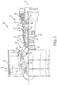
- FIG. 1 schematically illustrates a gas turbine engine 20.
- the gas turbine engine 20 is disclosed herein as a two-spool turbofan that generally incorporates a fan section 22, a compressor section 24, a combustor section 26 and a turbine section 28.
- the fan section 22, the compressor section 24, and the combustor section 26 are collectively known as a core engine 62.
- Alternative engines might include an augmentor section (not shown) among other systems or features.
- the fan section 22 drives air along a bypass flow path B in a bypass duct defined within a fan case 88 inside a nacelle 34 (shown in FIG. 2 ), while the compressor section 24 drives air along a core flow path C for compression and communication into the combustor section 26 then expansion through the turbine section 28.
- the exemplary gas turbine engine 20 generally includes a low speed spool 30 and a high speed spool 32 mounted for rotation about an engine central longitudinal axis A relative to an engine static structure 36 via several bearing systems 38. It should be understood that various bearing systems 38 at various locations may alternatively or additionally be provided, and the location of bearing systems 38 may be varied as appropriate to the application.
- the low speed spool 30 generally includes an inner shaft 40 that interconnects a fan 42, a low pressure compressor 44 and a low pressure turbine 46.
- the inner shaft 40 is connected to the fan 42 through a speed change mechanism, which in exemplary gas turbine engine 20 is illustrated as a geared architecture 48 to drive the fan 42 at a lower speed than the low speed spool 30.
- the high speed spool 32 includes an outer shaft 50 that interconnects a high pressure compressor 52 and a high pressure turbine 54.
- a combustor 56 is arranged in exemplary gas turbine 20 between the high pressure compressor 52 and the high pressure turbine 54.
- a mid-turbine frame 58 of the engine static structure 36 is arranged generally between the high pressure turbine 54 and the low pressure turbine 46.
- the mid-turbine frame 58 further supports bearing systems 38 in the turbine section 28.
- the inner shaft 40 and the outer shaft 50 are concentric and rotate via bearing systems 38 about the engine central longitudinal axis A which is collinear with their longitudinal axes.
- the core airflow is compressed by the low pressure compressor 44 then the high pressure compressor 52, mixed and burned with fuel in the combustor 56, then expanded over the high pressure turbine 54 and low pressure turbine 46.
- the mid-turbine frame 58 includes airfoils 60 which are in the core airflow path C.
- the high pressure turbine 54 and the low pressure turbine 46 rotationally drive the respective low speed spool 30 and high speed spool 32 in response to the expansion.
- each of the positions of the fan section 22, compressor section 24, combustor section 26, turbine section 28, and the geared architecture 48 may be varied.
- geared architecture 48 may be located aft of combustor section 26 or even aft of turbine section 28, and fan section 22 may be positioned forward or aft of the location of geared architecture 48.
- the gas turbine engine 20 in one example is a high-bypass geared aircraft engine.
- the gas turbine engine bypass ratio is greater than about six (6:1), with an example embodiment being greater than about ten (10:1)
- the geared architecture 48 is an epicyclic gear train, such as a planetary gear system or other gear system, with a gear reduction ratio of greater than about 2.3
- the low pressure turbine 46 has a pressure ratio that is greater than about five.
- the gas turbine engine bypass ratio is greater than about ten (10:1)
- the fan diameter is significantly larger than that of the low pressure compressor 44
- the low pressure turbine 46 has a pressure ratio that is greater than about five (5:1).
- Low pressure turbine 46 pressure ratio is pressure measured prior to inlet of low pressure turbine 46 as related to the pressure at the outlet of the low pressure turbine 46 prior to an exhaust nozzle.
- the geared architecture 48 may be an epicycle gear train, such as a planetary gear system or other gear system, with a gear reduction ratio of greater than about 2.3:1. It should be understood, however, that the above parameters are only exemplary of one embodiment of a geared architecture engine and that the present invention is applicable to other gas turbine engines including direct drive turbofans.
- a significant amount of thrust is provided by a bypass flowpath B due to the high bypass ratio.
- a fan duct inner (fixed) structure 64 surrounds the core engine 62
- the bypass flowpath B is provided by an inner flow surface 76 and an outer flow surface 78.
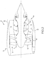
- the nacelle 34 encloses the fan case 88, core engine 62, fan duct inner (fixed structure) 64, upper and lower bifurcations 70 and 72, and a fan duct 84.
- a portion of the nacelle 34 that is aft of fan exit guide vanes 82 includes the fan duct inner structure 64, the upper bifurcation 70, and the lower bifurcation 72, which together define the fan duct 84.
- the upper bifurcation 70 and the lower bifurcation 72 may extend radially in the bypass flowpath B in locations opposite one another to accommodate wires, fluid conduits, engine mountings, or other components.
- the fan duct 84 in the nacelle 34 may be provided with thermal protection as this defines the boundary of the core compartment (i.e., more particularly, the area between the engine case and the nacelle, bounded by the fan duct inner structure 64 and portions of the upper and lower bifurcations 70 and 72 may be a "Designated Fire Zone” (DFZ)).
- the thickness of the thermal protection is often determined by the temperature of the core compartment after engine shutdown (i.e., "soakback conditions"). As the core compartment conventionally overheats after engine shutdown as previously described, the thickness of the thermal protection may be greater than 0.5 inches (1.27 cm) thick to provide an extra layer of fire protection for the core compartment should there be any fire in the core compartment/Designated Fire Zone.
- Nacelle 34 includes doors 85A and 85B, each with an outer diameter cowl 86.
- the nacelle 34 is split along the fan duct inner fixed structure 64, upper and lower bifurcations 70 and 72, and outer diameter cowl 86 into the doors 85A and 85B.
- the doors 85A and 85B (and the fan duct 84) open and close by pivoting on fan duct hinge lines 89 ( FIG. 2 ). When open, the core compartment of the gas turbine engine is exposed for maintenance or engine removal and replacement.
- One or more latching mechanisms e.g., 27 in FIG. 3 ) may secure the doors in a closed position.
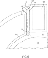
- An elastomeric pylon seal 118 is compressed between the fan duct inner structure 64 and a seal land of a pylon structure 102 ( FIG. 5 ) to provide sealing of the core compartment 66, a Designated Fire Zone.
- the seal may be used as a fire barrier, but unfortunately also traps hot air in the core compartment after engine shutdown.
- the doors 85A and 85B are fastened or otherwise connected to a pylon structure 102 that connects the gas turbine engine 20 to an aircraft.
- the terms upper and lower refer to a plane of reference relative to the pylon structure and would equally apply in other engine mount configurations.
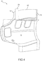
- a core compartment ventilation device 200 is depicted schematically as at least partially disposed in a gap 104 between adjacent external surfaces of the fan duct inner structure 64 and the pylon structure 102.
- the core compartment ventilation device 200 comprises a fireproof sealing member 202 in communication with a chimney 204.
- the fireproof sealing member 202 and the chimney 204 comprising the core compartment ventilation device comprise a passive assembly for providing a fire barrier and ventilation.
- the core compartment ventilation device 200 conducts hot air (indicated as arrow HA in FIGS. 4 and 5 ) away from the core compartment 66 and discharges the hot air into the external atmosphere.
- the fireproof sealing member 202 seals the core compartment 66.
- the fireproof sealing member 202 while providing a fire barrier, is not airtight and permits passage of the hot air therethrough, from the core compartment.
- the fireproof sealing member 202 may take the form of the labyrinth seal as shown schematically in FIG. 5 and should also be made of a fire resistant material.
- the core compartment ventilation device permits vertical passage of hot air from the core compartment 66. While a labyrinth seal is depicted, it is to be understood that other fireproof seals made from fireproof materials may be used as long as the fireproof seal allows for passage of the hot air from the core compartment through the seal. For example, a "turkey feather" seal or other types of seals may be used.
- the core compartment ventilation device serves a dual function as a fire barrier and to permit the passage of hot air from the core compartment to the chimney and thereafter, for discharge out into the external atmosphere (i.e., the atmosphere external to the nacelle).
- the fireproof sealing member and the chimney may be one-piece or multiple pieces coupled together.
- the core compartment ventilation device is rotatable about the fan duct hinge line 89.
- the chimney 204 comprises an elongated channel/chimney flue that conducts the hot air received from the fireproof sealing member to the external atmosphere.
- the chimney 204 comprises an inner portion that is adjacent an exit of the fireproof sealing member and an outer portion that extends exteriorly of the nacelle to be able to discharge the hot air into the atmosphere.
- the outer portion may be angled in a manner to discharge the hot air in the opposite direction of the pylon structure 102 as illustrated in FIG. 4 .
- the hot air discharged through the fireproof sealing member and the chimney generates an upward air current by the chimney effect, drawing cool air in through the lower bifurcation 72 to additionally cool the core compartment after engine shutdown.
- the core compartment ventilation device has been described as at least partially disposed between adjacent surfaces of the pylon structure and the fan duct inner structure of the nacelle, it is to be understood that the core compartment ventilation device may be disposed in other locations to provide fluid communication from the core compartment to the external atmosphere and provide the chimney effect.
- the core compartment ventilation device may be disposed primarily on the pylon structure 102 or through the pylon structure 102 as shown in FIG. 6 .
- Various embodiments thus permit hot air from the core compartment to be discharged into the atmosphere thereby cooling the core compartment after engine shutdown while, at the same time, preserving the fire barrier integrity of the core compartment.
- the core compartment ventilation device serves the dual function of removing the hot air from the core compartment while, at the same time, bringing cool air into the core compartment through the lower bifurcation via the chimney effect.
- the core compartment ventilation device also enables the thermal protection conventionally used on the fan duct inner structure 64 to be more lightweight, because of the lower temperatures of the core compartment that are provided by various embodiments. As a result, use of various embodiments may result in a reduced nacelle weight.
- Various embodiments also provide a passive system and assembly without failure modes that could compromise the fire barrier.
- references to "one embodiment”, “an embodiment”, “various embodiments”, etc. indicate that the embodiment described may include a particular feature, structure, or characteristic, but every embodiment may not necessarily include the particular feature, structure, or characteristic. Moreover, such phrases are not necessarily referring to the same embodiment. Further, when a particular feature, structure, or characteristic is described in connection with an embodiment, it is submitted that it is within the knowledge of one skilled in the art to affect such feature, structure, or characteristic in connection with other embodiments whether or not explicitly described. After reading the description, it will be apparent to one skilled in the relevant art(s) how to implement the disclosure in alternative embodiments.
Landscapes
- Engineering & Computer Science (AREA)
- Chemical & Material Sciences (AREA)
- Combustion & Propulsion (AREA)
- Mechanical Engineering (AREA)
- General Engineering & Computer Science (AREA)
- Aviation & Aerospace Engineering (AREA)
- Structures Of Non-Positive Displacement Pumps (AREA)
- Wind Motors (AREA)
Claims (12)
- Kernkammerbelüftungsvorrichtung für einen Gasturbinenmotor, umfassend:eine Kernkammer (66);ein feuerfestes Dichtungselement (202) zum wesentlichen Abdichten der Kernkammer (66) in einer Gondel (34) für den Gasturbinenmotor (20); undeinen Schornstein (204), der dazu konfiguriert ist, mit dem feuerfesten Dichtungselement (202) in Fluidverbindung zu stehen, um heiße Luft aus der Kernkammer (66) über das feuerfeste Dichtungselement (202) in die Außenatmosphäre zu leiten; wobeider Schornstein (204) einen länglichen Kanal umfasst und dazu konfiguriert ist, einen vertikalen Durchgang von heißer Luft aus der Kernkammer (66) zu ermöglichen.
- Kernkammerbelüftungsvorrichtung nach Anspruch 1, wobei das feuerfeste Dichtungselement (202) dazu konfiguriert ist, heiße Luft aus der Kernkammer (66) aufzunehmen und die heiße Luft in den Schornstein (204) leitet.
- Kernkammerbelüftungsvorrichtung nach Anspruch 1 oder 2, wobei das feuerfeste Dichtungselement (202) als Labyrinthdichtung konfiguriert ist.
- Kernkammerbelüftungsvorrichtung nach Anspruch 1, 2 oder 3, wobei das feuerfeste Dichtungselement (202) und der Schornstein (204), der die Kernkammerbelüftungsvorrichtung umfasst, eine passive Anordnung zum Bereitstellen einer Feuerbarriere und Belüftung umfassen.
- Gasturbinenmotor (20), umfassend:einen Lüfterkanal (84), der eine innere Struktur (64) des Lüfterkanals beinhaltet, die einen Kernmotor umgibt und die Kernkammer (66) einschließt und sich zwischen einer oberen Gabelung (70) und einer unteren Gabelung (72) erstreckt;ein Lüftergehäuse (88), das einen Lüfter (42) umgibt; unddie Kernkammerbelüftungsvorrichtung nach einem der vorhergehenden Ansprüche zum Abdichten der Kernkammer (66) gegen Feuer und zum Entlüften heißer Luft aus der Kernkammer (66) in die Außenatmosphäre.
- Gasturbinenmotor nach Anspruch 5, ferner umfassend eine Pylonstruktur (120) zum Verbinden des Gasturbinenmotors (20) mit einem Flugzeug.
- Gasturbinenmotor nach Anspruch 6, wobei die Pylonstruktur (102) mindestens einen Abschnitt der Kernkammerbelüftungsvorrichtung beinhaltet, der an mindestens einer Stelle von daran und darin angeordnet ist.
- Gasturbinenmotor nach Anspruch 6 oder 7, wobei die heiße Luft aus dem Schornstein (204) in einer Richtung entgegengesetzt zur Pylonstruktur (102) abgegeben wird.
- Gasturbinenmotor nach einem der Ansprüche 5 bis 8, wobei das feuerfeste Dichtungselement (202) eine Labyrinthdichtung aus einem feuerfesten Material umfasst.
- Gasturbinenmotor nach einem der Ansprüche 5 bis 9, wobei die Kernkammerbelüftungsvorrichtung einen Schornsteineffekt bewirkt, um Kühlluft durch die untere Gabelung (72) in die Kernkammer (66) zu ziehen.
- Gasturbinenmotor nach einem der Ansprüche 5 bis 10, wobei die Kernkammerbelüftungsvorrichtung um eine Lüfterkanal-Gelenklinie (89) drehbar ist.
- Gasturbinenmotor nach einem der Ansprüche 5 bis 11, wobei die Kernkammerbelüftungsvorrichtung nach dem Abstellen des Motors arbeitet.
Applications Claiming Priority (2)
| Application Number | Priority Date | Filing Date | Title |
|---|---|---|---|
| US14/981,229 US9976484B2 (en) | 2015-12-28 | 2015-12-28 | Core compartment ventilation devices for nacelles of gas turbine engines for cooling a core compartment of a gas turbine engine |
| EP16205550.3A EP3187718B1 (de) | 2015-12-28 | 2016-12-20 | Kernfachbelüftungsvorrichtungen für gondeln von gasturbinenmotoren zum kühlen eines kernfachs eines gasturbinenmotors |
Related Parent Applications (2)
| Application Number | Title | Priority Date | Filing Date |
|---|---|---|---|
| EP16205550.3A Division EP3187718B1 (de) | 2015-12-28 | 2016-12-20 | Kernfachbelüftungsvorrichtungen für gondeln von gasturbinenmotoren zum kühlen eines kernfachs eines gasturbinenmotors |
| EP16205550.3A Division-Into EP3187718B1 (de) | 2015-12-28 | 2016-12-20 | Kernfachbelüftungsvorrichtungen für gondeln von gasturbinenmotoren zum kühlen eines kernfachs eines gasturbinenmotors |
Publications (2)
| Publication Number | Publication Date |
|---|---|
| EP3567235A1 EP3567235A1 (de) | 2019-11-13 |
| EP3567235B1 true EP3567235B1 (de) | 2021-04-28 |
Family
ID=57681342
Family Applications (2)
| Application Number | Title | Priority Date | Filing Date |
|---|---|---|---|
| EP16205550.3A Active EP3187718B1 (de) | 2015-12-28 | 2016-12-20 | Kernfachbelüftungsvorrichtungen für gondeln von gasturbinenmotoren zum kühlen eines kernfachs eines gasturbinenmotors |
| EP19182832.6A Active EP3567235B1 (de) | 2015-12-28 | 2016-12-20 | Kernkammerbelüftungsvorrichtungen für gondeln von gasturbinenmotoren zum kühlen einer kernkammer eines gasturbinenmotors |
Family Applications Before (1)
| Application Number | Title | Priority Date | Filing Date |
|---|---|---|---|
| EP16205550.3A Active EP3187718B1 (de) | 2015-12-28 | 2016-12-20 | Kernfachbelüftungsvorrichtungen für gondeln von gasturbinenmotoren zum kühlen eines kernfachs eines gasturbinenmotors |
Country Status (2)
| Country | Link |
|---|---|
| US (1) | US9976484B2 (de) |
| EP (2) | EP3187718B1 (de) |
Cited By (1)
| Publication number | Priority date | Publication date | Assignee | Title |
|---|---|---|---|---|
| EP4464882A1 (de) * | 2023-05-16 | 2024-11-20 | Pratt & Whitney Canada Corp. | Flugzeugmotorabgasrückflussverhinderung |
Families Citing this family (13)
| Publication number | Priority date | Publication date | Assignee | Title |
|---|---|---|---|---|
| US10563671B2 (en) * | 2016-08-18 | 2020-02-18 | United Technologies Corporation | Method and apparatus for cooling thrust reverser seal |
| US10759541B2 (en) * | 2016-10-14 | 2020-09-01 | Rohr, Inc. | Nacelle bifurcation with leading edge structure |
| US20180149086A1 (en) * | 2016-11-29 | 2018-05-31 | General Electric Company | Turbine engine and method of cooling thereof |
| US10794327B2 (en) | 2018-03-21 | 2020-10-06 | Honeywell International Inc. | Systems and methods for thrust reverser with temperature and fluid management |
| US11002222B2 (en) | 2018-03-21 | 2021-05-11 | Honeywell International Inc. | Systems and methods for thrust reverser with temperature and fluid management |
| US11230975B2 (en) | 2019-03-20 | 2022-01-25 | Raytheon Technologies Corporation | Modulated fire extinguishing vent for a gas turbine engine |
| US11719113B2 (en) | 2020-02-05 | 2023-08-08 | Raytheon Technologies Corporation | Cooling system for power cables in a gas turbine engine |
| US11047306B1 (en) | 2020-02-25 | 2021-06-29 | General Electric Company | Gas turbine engine reverse bleed for coking abatement |
| US11585291B2 (en) | 2020-09-11 | 2023-02-21 | Raytheon Technologies Corporation | Tail cone ejector for power cable cooling system in a gas turbine engine |
| US11578657B2 (en) | 2020-10-27 | 2023-02-14 | Raytheon Technologies Corporation | Power cable cooling system in a gas turbine engine |
| US12031484B2 (en) | 2021-01-28 | 2024-07-09 | General Electric Company | Gas turbine engine cooling system control |
| US12180911B2 (en) * | 2023-04-21 | 2024-12-31 | Rtx Corporation | Ducted firewall with upper bifi bleed for modulated core ventilation |
| FR3151299B1 (fr) | 2023-07-20 | 2025-08-01 | Airbus Operations Sas | Ensemble propulsif pour aéronef |
Family Cites Families (9)
| Publication number | Priority date | Publication date | Assignee | Title |
|---|---|---|---|---|
| DE3605619A1 (de) * | 1986-02-21 | 1987-08-27 | Mtu Muenchen Gmbh | Stroemungsmaschine mit versorgungseinrichtung fuer schmiermittel |
| US5251435A (en) * | 1991-10-30 | 1993-10-12 | General Electric Company | Reverser inner cowl with integral bifurcation walls and core cowl |
| US5910094A (en) | 1996-09-10 | 1999-06-08 | The Boeing Company | Aircraft labyrinth fire seal |
| FR2905358B1 (fr) * | 2006-09-06 | 2008-10-17 | Eurocopter France | Cloison pare-feu d'aeronef. |
| US9835090B2 (en) * | 2012-09-18 | 2017-12-05 | United Technologies Corporation | Fire seal for a gas turbine engine |
| US10280838B2 (en) * | 2014-03-28 | 2019-05-07 | Brent Lee | Engine, biomass powder energy conversion and/or generation system, hybrid engines including the same, and methods of making and using the same |
| DE102014220296A1 (de) * | 2014-10-07 | 2016-04-07 | Dürr Systems GmbH | (Mikro-)Gasturbinenanordnung |
| US9650149B2 (en) * | 2014-12-08 | 2017-05-16 | Honeywell International Inc. | Fire containment apparatuses for aircraft duct assemblies |
| US10203114B2 (en) * | 2016-03-04 | 2019-02-12 | General Electric Company | Sleeve assemblies and methods of fabricating same |
-
2015
- 2015-12-28 US US14/981,229 patent/US9976484B2/en active Active
-
2016
- 2016-12-20 EP EP16205550.3A patent/EP3187718B1/de active Active
- 2016-12-20 EP EP19182832.6A patent/EP3567235B1/de active Active
Non-Patent Citations (1)
| Title |
|---|
| None * |
Cited By (1)
| Publication number | Priority date | Publication date | Assignee | Title |
|---|---|---|---|---|
| EP4464882A1 (de) * | 2023-05-16 | 2024-11-20 | Pratt & Whitney Canada Corp. | Flugzeugmotorabgasrückflussverhinderung |
Also Published As
| Publication number | Publication date |
|---|---|
| EP3567235A1 (de) | 2019-11-13 |
| US9976484B2 (en) | 2018-05-22 |
| US20170184025A1 (en) | 2017-06-29 |
| EP3187718B1 (de) | 2019-08-07 |
| EP3187718A1 (de) | 2017-07-05 |
Similar Documents
| Publication | Publication Date | Title |
|---|---|---|
| EP3567235B1 (de) | Kernkammerbelüftungsvorrichtungen für gondeln von gasturbinenmotoren zum kühlen einer kernkammer eines gasturbinenmotors | |
| EP3115588B1 (de) | Gekühltes kühlluftsystem für ein turbofan-triebwerk | |
| EP3106646B1 (de) | Gebläsetriebwerk mit einem kühlluftsystem sowie ein dazugehöriges verfahren | |
| US9879599B2 (en) | Nacelle anti-ice valve utilized as compressor stability bleed valve during starting | |
| EP3483411B1 (de) | Gekühltes kühlluftsystem mit absperrventil und antrieb | |
| US9835090B2 (en) | Fire seal for a gas turbine engine | |
| US10633998B2 (en) | Active clearance control for gas turbine engine | |
| EP3126640B1 (de) | Aktive spielraumsteuerung für einen gasturbinenmotor | |
| US10815884B2 (en) | Gas turbine engine de-icing system | |
| EP2971680A2 (de) | Kronenverriegelungsmechanismus für einen gasturbinenmotor | |
| US9938842B2 (en) | Leakage air systems for turbomachines | |
| US10107131B2 (en) | Fan drive thrust balance | |
| EP3045708B1 (de) | Gasturbinenmotor mit einem oberen rahmen und verfahren um luftverlust zu verhindern | |
| US10330019B2 (en) | Self-actuating and dual pivot flapper valve | |
| US20140116752A1 (en) | Lower firewall plate grommet | |
| US9482157B2 (en) | Bifurcation fire purge system for a gas turbine engine | |
| EP3284914B1 (de) | Verfahren und vorrichtung zum kühlen einer nebenstromkanaldichtung | |
| US9957815B2 (en) | Gas powered turbine component including serpentine cooling |
Legal Events
| Date | Code | Title | Description |
|---|---|---|---|
| PUAI | Public reference made under article 153(3) epc to a published international application that has entered the european phase |
Free format text: ORIGINAL CODE: 0009012 |
|
| STAA | Information on the status of an ep patent application or granted ep patent |
Free format text: STATUS: THE APPLICATION HAS BEEN PUBLISHED |
|
| AC | Divisional application: reference to earlier application |
Ref document number: 3187718 Country of ref document: EP Kind code of ref document: P |
|
| AK | Designated contracting states |
Kind code of ref document: A1 Designated state(s): AL AT BE BG CH CY CZ DE DK EE ES FI FR GB GR HR HU IE IS IT LI LT LU LV MC MK MT NL NO PL PT RO RS SE SI SK SM TR |
|
| STAA | Information on the status of an ep patent application or granted ep patent |
Free format text: STATUS: REQUEST FOR EXAMINATION WAS MADE |
|
| 17P | Request for examination filed |
Effective date: 20200513 |
|
| RBV | Designated contracting states (corrected) |
Designated state(s): AL AT BE BG CH CY CZ DE DK EE ES FI FR GB GR HR HU IE IS IT LI LT LU LV MC MK MT NL NO PL PT RO RS SE SI SK SM TR |
|
| GRAP | Despatch of communication of intention to grant a patent |
Free format text: ORIGINAL CODE: EPIDOSNIGR1 |
|
| STAA | Information on the status of an ep patent application or granted ep patent |
Free format text: STATUS: GRANT OF PATENT IS INTENDED |
|
| INTG | Intention to grant announced |
Effective date: 20201123 |
|
| GRAS | Grant fee paid |
Free format text: ORIGINAL CODE: EPIDOSNIGR3 |
|
| RAP1 | Party data changed (applicant data changed or rights of an application transferred) |
Owner name: RAYTHEON TECHNOLOGIES CORPORATION |
|
| GRAA | (expected) grant |
Free format text: ORIGINAL CODE: 0009210 |
|
| STAA | Information on the status of an ep patent application or granted ep patent |
Free format text: STATUS: THE PATENT HAS BEEN GRANTED |
|
| AC | Divisional application: reference to earlier application |
Ref document number: 3187718 Country of ref document: EP Kind code of ref document: P |
|
| AK | Designated contracting states |
Kind code of ref document: B1 Designated state(s): AL AT BE BG CH CY CZ DE DK EE ES FI FR GB GR HR HU IE IS IT LI LT LU LV MC MK MT NL NO PL PT RO RS SE SI SK SM TR |
|
| REG | Reference to a national code |
Ref country code: GB Ref legal event code: FG4D |
|
| REG | Reference to a national code |
Ref country code: CH Ref legal event code: EP |
|
| REG | Reference to a national code |
Ref country code: DE Ref legal event code: R096 Ref document number: 602016057204 Country of ref document: DE |
|
| REG | Reference to a national code |
Ref country code: AT Ref legal event code: REF Ref document number: 1387308 Country of ref document: AT Kind code of ref document: T Effective date: 20210515 |
|
| REG | Reference to a national code |
Ref country code: IE Ref legal event code: FG4D |
|
| REG | Reference to a national code |
Ref country code: LT Ref legal event code: MG9D |
|
| REG | Reference to a national code |
Ref country code: AT Ref legal event code: MK05 Ref document number: 1387308 Country of ref document: AT Kind code of ref document: T Effective date: 20210428 |
|
| PG25 | Lapsed in a contracting state [announced via postgrant information from national office to epo] |
Ref country code: FI Free format text: LAPSE BECAUSE OF FAILURE TO SUBMIT A TRANSLATION OF THE DESCRIPTION OR TO PAY THE FEE WITHIN THE PRESCRIBED TIME-LIMIT Effective date: 20210428 Ref country code: HR Free format text: LAPSE BECAUSE OF FAILURE TO SUBMIT A TRANSLATION OF THE DESCRIPTION OR TO PAY THE FEE WITHIN THE PRESCRIBED TIME-LIMIT Effective date: 20210428 Ref country code: LT Free format text: LAPSE BECAUSE OF FAILURE TO SUBMIT A TRANSLATION OF THE DESCRIPTION OR TO PAY THE FEE WITHIN THE PRESCRIBED TIME-LIMIT Effective date: 20210428 Ref country code: NL Free format text: LAPSE BECAUSE OF FAILURE TO SUBMIT A TRANSLATION OF THE DESCRIPTION OR TO PAY THE FEE WITHIN THE PRESCRIBED TIME-LIMIT Effective date: 20210428 Ref country code: BG Free format text: LAPSE BECAUSE OF FAILURE TO SUBMIT A TRANSLATION OF THE DESCRIPTION OR TO PAY THE FEE WITHIN THE PRESCRIBED TIME-LIMIT Effective date: 20210728 Ref country code: AT Free format text: LAPSE BECAUSE OF FAILURE TO SUBMIT A TRANSLATION OF THE DESCRIPTION OR TO PAY THE FEE WITHIN THE PRESCRIBED TIME-LIMIT Effective date: 20210428 |
|
| PG25 | Lapsed in a contracting state [announced via postgrant information from national office to epo] |
Ref country code: IS Free format text: LAPSE BECAUSE OF FAILURE TO SUBMIT A TRANSLATION OF THE DESCRIPTION OR TO PAY THE FEE WITHIN THE PRESCRIBED TIME-LIMIT Effective date: 20210828 Ref country code: GR Free format text: LAPSE BECAUSE OF FAILURE TO SUBMIT A TRANSLATION OF THE DESCRIPTION OR TO PAY THE FEE WITHIN THE PRESCRIBED TIME-LIMIT Effective date: 20210729 Ref country code: PL Free format text: LAPSE BECAUSE OF FAILURE TO SUBMIT A TRANSLATION OF THE DESCRIPTION OR TO PAY THE FEE WITHIN THE PRESCRIBED TIME-LIMIT Effective date: 20210428 Ref country code: NO Free format text: LAPSE BECAUSE OF FAILURE TO SUBMIT A TRANSLATION OF THE DESCRIPTION OR TO PAY THE FEE WITHIN THE PRESCRIBED TIME-LIMIT Effective date: 20210728 Ref country code: LV Free format text: LAPSE BECAUSE OF FAILURE TO SUBMIT A TRANSLATION OF THE DESCRIPTION OR TO PAY THE FEE WITHIN THE PRESCRIBED TIME-LIMIT Effective date: 20210428 Ref country code: PT Free format text: LAPSE BECAUSE OF FAILURE TO SUBMIT A TRANSLATION OF THE DESCRIPTION OR TO PAY THE FEE WITHIN THE PRESCRIBED TIME-LIMIT Effective date: 20210830 Ref country code: SE Free format text: LAPSE BECAUSE OF FAILURE TO SUBMIT A TRANSLATION OF THE DESCRIPTION OR TO PAY THE FEE WITHIN THE PRESCRIBED TIME-LIMIT Effective date: 20210428 Ref country code: RS Free format text: LAPSE BECAUSE OF FAILURE TO SUBMIT A TRANSLATION OF THE DESCRIPTION OR TO PAY THE FEE WITHIN THE PRESCRIBED TIME-LIMIT Effective date: 20210428 |
|
| REG | Reference to a national code |
Ref country code: NL Ref legal event code: MP Effective date: 20210428 |
|
| PG25 | Lapsed in a contracting state [announced via postgrant information from national office to epo] |
Ref country code: SK Free format text: LAPSE BECAUSE OF FAILURE TO SUBMIT A TRANSLATION OF THE DESCRIPTION OR TO PAY THE FEE WITHIN THE PRESCRIBED TIME-LIMIT Effective date: 20210428 Ref country code: EE Free format text: LAPSE BECAUSE OF FAILURE TO SUBMIT A TRANSLATION OF THE DESCRIPTION OR TO PAY THE FEE WITHIN THE PRESCRIBED TIME-LIMIT Effective date: 20210428 Ref country code: ES Free format text: LAPSE BECAUSE OF FAILURE TO SUBMIT A TRANSLATION OF THE DESCRIPTION OR TO PAY THE FEE WITHIN THE PRESCRIBED TIME-LIMIT Effective date: 20210428 Ref country code: CZ Free format text: LAPSE BECAUSE OF FAILURE TO SUBMIT A TRANSLATION OF THE DESCRIPTION OR TO PAY THE FEE WITHIN THE PRESCRIBED TIME-LIMIT Effective date: 20210428 Ref country code: DK Free format text: LAPSE BECAUSE OF FAILURE TO SUBMIT A TRANSLATION OF THE DESCRIPTION OR TO PAY THE FEE WITHIN THE PRESCRIBED TIME-LIMIT Effective date: 20210428 Ref country code: SM Free format text: LAPSE BECAUSE OF FAILURE TO SUBMIT A TRANSLATION OF THE DESCRIPTION OR TO PAY THE FEE WITHIN THE PRESCRIBED TIME-LIMIT Effective date: 20210428 Ref country code: RO Free format text: LAPSE BECAUSE OF FAILURE TO SUBMIT A TRANSLATION OF THE DESCRIPTION OR TO PAY THE FEE WITHIN THE PRESCRIBED TIME-LIMIT Effective date: 20210428 |
|
| REG | Reference to a national code |
Ref country code: DE Ref legal event code: R097 Ref document number: 602016057204 Country of ref document: DE |
|
| PLBE | No opposition filed within time limit |
Free format text: ORIGINAL CODE: 0009261 |
|
| STAA | Information on the status of an ep patent application or granted ep patent |
Free format text: STATUS: NO OPPOSITION FILED WITHIN TIME LIMIT |
|
| 26N | No opposition filed |
Effective date: 20220131 |
|
| PG25 | Lapsed in a contracting state [announced via postgrant information from national office to epo] |
Ref country code: IS Free format text: LAPSE BECAUSE OF FAILURE TO SUBMIT A TRANSLATION OF THE DESCRIPTION OR TO PAY THE FEE WITHIN THE PRESCRIBED TIME-LIMIT Effective date: 20210828 Ref country code: AL Free format text: LAPSE BECAUSE OF FAILURE TO SUBMIT A TRANSLATION OF THE DESCRIPTION OR TO PAY THE FEE WITHIN THE PRESCRIBED TIME-LIMIT Effective date: 20210428 |
|
| PG25 | Lapsed in a contracting state [announced via postgrant information from national office to epo] |
Ref country code: MC Free format text: LAPSE BECAUSE OF FAILURE TO SUBMIT A TRANSLATION OF THE DESCRIPTION OR TO PAY THE FEE WITHIN THE PRESCRIBED TIME-LIMIT Effective date: 20210428 Ref country code: IT Free format text: LAPSE BECAUSE OF FAILURE TO SUBMIT A TRANSLATION OF THE DESCRIPTION OR TO PAY THE FEE WITHIN THE PRESCRIBED TIME-LIMIT Effective date: 20210428 |
|
| REG | Reference to a national code |
Ref country code: CH Ref legal event code: PL |
|
| REG | Reference to a national code |
Ref country code: BE Ref legal event code: MM Effective date: 20211231 |
|
| PG25 | Lapsed in a contracting state [announced via postgrant information from national office to epo] |
Ref country code: LU Free format text: LAPSE BECAUSE OF NON-PAYMENT OF DUE FEES Effective date: 20211220 Ref country code: IE Free format text: LAPSE BECAUSE OF NON-PAYMENT OF DUE FEES Effective date: 20211220 |
|
| PG25 | Lapsed in a contracting state [announced via postgrant information from national office to epo] |
Ref country code: BE Free format text: LAPSE BECAUSE OF NON-PAYMENT OF DUE FEES Effective date: 20211231 |
|
| PG25 | Lapsed in a contracting state [announced via postgrant information from national office to epo] |
Ref country code: LI Free format text: LAPSE BECAUSE OF NON-PAYMENT OF DUE FEES Effective date: 20211231 Ref country code: CH Free format text: LAPSE BECAUSE OF NON-PAYMENT OF DUE FEES Effective date: 20211231 |
|
| P01 | Opt-out of the competence of the unified patent court (upc) registered |
Effective date: 20230521 |
|
| PG25 | Lapsed in a contracting state [announced via postgrant information from national office to epo] |
Ref country code: CY Free format text: LAPSE BECAUSE OF FAILURE TO SUBMIT A TRANSLATION OF THE DESCRIPTION OR TO PAY THE FEE WITHIN THE PRESCRIBED TIME-LIMIT Effective date: 20210428 |
|
| PG25 | Lapsed in a contracting state [announced via postgrant information from national office to epo] |
Ref country code: HU Free format text: LAPSE BECAUSE OF FAILURE TO SUBMIT A TRANSLATION OF THE DESCRIPTION OR TO PAY THE FEE WITHIN THE PRESCRIBED TIME-LIMIT; INVALID AB INITIO Effective date: 20161220 |
|
| PG25 | Lapsed in a contracting state [announced via postgrant information from national office to epo] |
Ref country code: MK Free format text: LAPSE BECAUSE OF FAILURE TO SUBMIT A TRANSLATION OF THE DESCRIPTION OR TO PAY THE FEE WITHIN THE PRESCRIBED TIME-LIMIT Effective date: 20210428 |
|
| PG25 | Lapsed in a contracting state [announced via postgrant information from national office to epo] |
Ref country code: TR Free format text: LAPSE BECAUSE OF FAILURE TO SUBMIT A TRANSLATION OF THE DESCRIPTION OR TO PAY THE FEE WITHIN THE PRESCRIBED TIME-LIMIT Effective date: 20210428 |
|
| PG25 | Lapsed in a contracting state [announced via postgrant information from national office to epo] |
Ref country code: MT Free format text: LAPSE BECAUSE OF FAILURE TO SUBMIT A TRANSLATION OF THE DESCRIPTION OR TO PAY THE FEE WITHIN THE PRESCRIBED TIME-LIMIT Effective date: 20210428 |
|
| REG | Reference to a national code |
Ref country code: DE Ref legal event code: R081 Ref document number: 602016057204 Country of ref document: DE Owner name: RTX CORPORATION (N.D.GES.D. STAATES DELAWARE),, US Free format text: FORMER OWNER: RAYTHEON TECHNOLOGIES CORPORATION, FARMINGTON, CT, US |
|
| PGFP | Annual fee paid to national office [announced via postgrant information from national office to epo] |
Ref country code: DE Payment date: 20251126 Year of fee payment: 10 |
|
| PGFP | Annual fee paid to national office [announced via postgrant information from national office to epo] |
Ref country code: GB Payment date: 20251120 Year of fee payment: 10 |
|
| PGFP | Annual fee paid to national office [announced via postgrant information from national office to epo] |
Ref country code: FR Payment date: 20251120 Year of fee payment: 10 |