EP3567180A1 - A kit of parts for flashing a roof element and a method of flashing a roof element using such kit of parts - Google Patents
A kit of parts for flashing a roof element and a method of flashing a roof element using such kit of parts Download PDFInfo
- Publication number
- EP3567180A1 EP3567180A1 EP19173060.5A EP19173060A EP3567180A1 EP 3567180 A1 EP3567180 A1 EP 3567180A1 EP 19173060 A EP19173060 A EP 19173060A EP 3567180 A1 EP3567180 A1 EP 3567180A1
- Authority
- EP
- European Patent Office
- Prior art keywords
- roof
- flashing
- roof element
- locking
- locking strip
- Prior art date
- Legal status (The legal status is an assumption and is not a legal conclusion. Google has not performed a legal analysis and makes no representation as to the accuracy of the status listed.)
- Granted
Links
Images




Classifications
-
- E—FIXED CONSTRUCTIONS
- E04—BUILDING
- E04D—ROOF COVERINGS; SKY-LIGHTS; GUTTERS; ROOF-WORKING TOOLS
- E04D13/00—Special arrangements or devices in connection with roof coverings; Protection against birds; Roof drainage ; Sky-lights
- E04D13/14—Junctions of roof sheathings to chimneys or other parts extending above the roof
- E04D13/147—Junctions of roof sheathings to chimneys or other parts extending above the roof specially adapted for inclined roofs
- E04D13/1473—Junctions of roof sheathings to chimneys or other parts extending above the roof specially adapted for inclined roofs specially adapted to the cross-section of the parts extending above the roof
- E04D13/1475—Junctions of roof sheathings to chimneys or other parts extending above the roof specially adapted for inclined roofs specially adapted to the cross-section of the parts extending above the roof wherein the parts extending above the roof have a generally rectangular cross-section
-
- E—FIXED CONSTRUCTIONS
- E04—BUILDING
- E04D—ROOF COVERINGS; SKY-LIGHTS; GUTTERS; ROOF-WORKING TOOLS
- E04D13/00—Special arrangements or devices in connection with roof coverings; Protection against birds; Roof drainage ; Sky-lights
- E04D13/14—Junctions of roof sheathings to chimneys or other parts extending above the roof
- E04D13/147—Junctions of roof sheathings to chimneys or other parts extending above the roof specially adapted for inclined roofs
Definitions
- the present invention relates to a kit of parts for flashing a roof element, such as a roof window, in a sloping roof with a roof covering comprising flat roofing panels, possibly of sheet metal, said kit of parts comprising an upper flashing member, two side flashing members and a bottom flashing member, said flashing members respectively having a generally L-shaped cross-section with a first leg configured to be arranged against a side of the roof element and a second leg configured to extend parallel to a plane of the roof covering, whereby the second legs of the upper flashing member and the side flashing members are configured to be at least in part positioned beneath the roof covering and the bottom flashing member comprises a second leg, possibly including a flexible skirt, configured to be at least in part positioned above the roof covering to seal between the roof element and the roof covering.
- the invention relates to a method of flashing a roof element, such as a roof window, in a sloping roof with a roof covering comprising flat roofing panels, possibly of sheet metal, using such kit of parts, wherein the method comprises the steps of:
- Sloping roofs with a roof covering comprising flat roofing panels, e.g. of sheet metal or plastics, are known to comprise a carrying structure below the roofing panels, which are provided in the form of longitudinal roofing panels that are mounted to extend in the sloping direction of the roof, i.e. perpendicular to a horizontal direction.
- the roofing panels may come in lengths sufficient for one roofing panel to cover the entire length of a face of the roof in the sloping direction.
- Adjacent roofing panels are joined by seams, usually standing seams extending upwards from a common plane of the roofing panels covering a given surface of the roof.
- the carrying structure may comprise plywood, hard insulating foam, similar hard underroof constructions, etc.
- full roofing panel should herein be understood a roofing panel that is not cut due to regard to the roof element in question.
- a flashing arrangement comprising flashing members is used to provide for sealing between the roof covering, that is in the present case the roofing panels, and the roof element.
- a flashing arrangement comprising flashing members is used to provide for sealing between the roof covering, that is in the present case the roofing panels, and the roof element.
- flashing care should be taken to ensure a sealing connection between the flashing members and the roofing panels.
- the object of the present invention is to provide a kit of parts to facilitate the process of flashing a roof element to adequately seal between the flashing members and the roofing panels such that precipitation is greatly prevented from penetrating the roof around the roof element in bad weather conditions.
- a kit of parts as mentioned by way of introduction that is characterized by a locking strip configured to engage with a folded edge of the roof covering, said locking strip being elongate with two mutually opposite, longitudinal side edges and having a single bend in a single direction between the two longitudinal side edges whereby one of the longitudinal side edges is raised from a mounting surface, such as the surface of the second leg of a flashing member, when the locking strip is positioned with the opposite, longitudinal side edge against said mounting surface, a concave side of the locking strip facing away from said mounting surface.
- the locking strip provides for fastening, in a convenient manner, an edge of a roofing panel to a subjacent surface, e.g.
- the locking strip per se is preferably mounted by means of penetrating fastening means, such as nails or screws to the underlying carrying structure the fastening means thereby penetrating the element comprising the subjacent surface.
- a sealing material which also could have adhesive properties, may be applied between the locking strip and the subjacent surface to seal between the locking strip and the subjacent surface.
- the locking strip may comprise a piece of material with constant thickness such as a piece of metal or plastic with suitable strength.
- the kit of part comprises at least three locking strips. Thereby is provided for fastening the lower edge of a roofing panel above the roof element along an upper side of the roof element and past corners thereof to provide good sealing as well as a neat transition between the upper flashing member and the adjacent roofing panel(s).
- a first locking strip may be pre-mounted on the upper flashing member e.g. by means of an adhesive.
- the mutually opposite, longitudinal side edges of the locking strip are parallel.
- the locking strip may have a V-shaped cross-section. Such shape provides for simple production by bending along a single line a piece of flat material.
- the single bend extends centrally between the mutually opposite, longitudinal side edges of the locking strip.
- a symmetric locking strip is provided facilitating mounting as it may be turned 180° without disturbing the mounting.
- the concave side of the locking strip due to the bend defines an angle of approx. 173°-178°, especially approx. 175°. This provides for the raised side edge to be raised to a suitable degree for engaging with a folded side edge of a roofing panel.
- the object is further obtained by a method as mentioned in the above, second paragraph, which is characterized in that between at least one of steps c) and d) and steps e) and f) at least one locking strip is mounted for engagement with a folded lower edge of the subsequently mounted roofing panel.
- a method as mentioned in the above, second paragraph which is characterized in that between at least one of steps c) and d) and steps e) and f) at least one locking strip is mounted for engagement with a folded lower edge of the subsequently mounted roofing panel.
- a locking strip having a single bend in a single direction between the two longitudinal side edges, whereby one of the longitudinal side edges is raised from a mounting surface provides the benefits that on one hand the raised longitudinal side edge may be raised relatively high from the mounting surface facilitating catching said side edge during mounting of a superjacent element, such as a roofing panel with a folded lower edge, and the single bend, that provides a generally V-shaped cross section, further entails that the folded lower edge of the superjacent roofing panel will be drawn towards the mounting surface when the superjacent roofing panel is moved into full engagement with the locking strip during the fitting and mounting of the superjacent roofing panel.
- three locking strips are mounted at an upper end of the roof element between steps e) and f) whereby a first locking strip is mounted above the roof element in a horizontal position and two second locking strips are mounted at either end of the first locking strip to extend downwards at oblique angles past upper corners of the roof element.
- a first locking strip is mounted above the roof element in a horizontal position and two second locking strips are mounted at either end of the first locking strip to extend downwards at oblique angles past upper corners of the roof element.
- the oblique angles are in some embodiments between 20° and 45° relative to the sloping direction, and in further embodiments the oblique angles are in the range of approx. 30°-35°.
- third locking strips are mounted in extension of the second locking strips at a different angle closer to horizontal than said oblique angles or horizontally to extend towards seams next to the roof element between joined roofing panels.
- additional locking strips are mounted at a lower end of the roof element between steps c) and d), whereby the additional locking strips are mounted to extend from respective ends of a horizontal lower edge of the second leg of the bottom flashing member, said additional locking strips thereby extending in a horizontal direction or an obliquely downward direction towards seams next to the roof element between joined roofing panels.
- the roofing panels mounted on either side of the roof element to extend from lower corners of the roof element across respective ends of the second leg and possibly the flexible skirt of the bottom flashing member to be fastened to the additional locking strips thus holding the second leg and possibly the flexible skirt of the bottom flashing member against the underlying roofing panel below the roof element.
- a locking strip extending to "the vicinity" of a seam includes locking strips extending close, but in a non-sealing manner, to the seam in question.
- said locking strips may extend only to a point at a distance from the seam, said distance being not so big that the effect of fastening an edge of an adjacent roofing panel is negatively affected.
- the kit of parts is intended for flashing a roof element mounted in a sloping roof.
- a roof window 6 is used as an example of such roof element, but the invention is not limited to roof windows.
- roof elements as such comprise e.g. solar panels, etc.
- kit of parts is intended for flashing a roof element mounted in a sloping roof with a roof covering comprising flat material, such as sheet metal or plastic, e.g. provided as longitudinal roofing panels 41.
- a roof covering comprising sheet metal, roofing panels 41 installed in the sloping direction of the roof, i.e. perpendicular to horizontal, whereby adjacent roofing panels 41 are joined by standing seams 42.
- the second legs 12, 22 of the upper flashing member 1 and the side flashing members 2 are configured to be at least in part positioned beneath the roof covering 4, whereby respective outer edges 13, 23, relative to the corner of the L-shape, are folded, in a manner known per se, to prevent water from flowing over said edges 13, 23 below the roof covering 4, see Fig. 2 .
- the second leg 32 of the bottom flashing member 3 includes, in a manner known per se, a flexible skirt 33 configured to be at least in part positioned above the roof covering to seal between the roof element and the roof covering.
- the locking strips 5 comprise flat pieces of material of suitable strength, such as metal or plastic, with mutually opposite, parallel, longitudinal side edges 51a, 51b.
- the locking strips 5 are bend along a line 52, which in the shown embodiment is positioned centrally between the longitudinal side edges 51a, 51b. Thereby the locking strip is symmetric and easy to install. Due to the bend the locking strip 5 has a V-shaped cross-section with a concave side defining an angle of approx. 173°-178°, especially approx. 175°.
- Fig. 2 illustrates the sealing and fastening effect of the locking strips 5.
- Fig. 2 shows the roof window 6 mounted in the sloping roof with the roof covering 4 comprising the roofing panels 41, that are mutually joined by standing seams 42.
- the upper flashing member 1 has its first leg 11 positioned against the side of the window frame 61 and the second leg 12 is extending below the roofing panel 41 positioned next to and above the window 6.
- a first locking strip 105 is mounted on the second leg 12 of the upper flashing member 1 to extend in a horizontal direction parallel to the first leg 11.
- a first, longitudinal side edge 51a is in abutment against the surface of the second leg 12. Due to the mounted position of the first locking strip 105, the first, longitudinal side edge 51a is an upper, longitudinal side edge.
- a correspondingly lower, second, longitudinal side edge 51b is raised from the surface of the second leg 12 due to the V-shape of the locking strip 105. Thereby the second, longitudinal side edge 51b extends at an angle ⁇ of 2°-7°, in the present embodiment 5°, relative to the surface of the second leg 12.
- the locking strip 105 is sealed and adhered, e.g.
- the locking strip 105 provides for fastening, in a convenient manner, the edge 43 of the roofing panel 41 to the subjacent surface, i.e. the upper surface of the second leg 12 of the upper flashing member 1.
- the locking strip might provide or fastening an edge of a roofing panel to an upper surface of e.g. another roofing panel adjacent the roof element.
- the locking strip 105 further provides for sealing against water on the roof that in bad weather conditions might migrate up below the edge of the roofing panel 41.
- Fig. 3 shows the arrangement of locking strips in a first example of flashing a roof window 6.
- standing seams 42 between adjacent roofing panels 41 are positioned close to the roof window 6.
- a full roofing panel 141 is mounted at one side of the roof window 6, in the present example to the left of the roof window 6 as seen in Fig. 3 , that shows the roof window 6 seen from the outside in a direction of view perpendicular to the surface of the roof covering.
- lower roofing panels 241 are adapted in their longitudinal direction having regard to the roof window 6, and the lower roofing panels 241 are mounted.
- the bottom flashing member 3 is mounted. Possibly the ends of the second leg 32 and thus of the skirt 33 are cut to adapt the horizontal length of the bottom flashing member 3 to the distance between the adjacent standing seams 42.
- Side roofing panels 341 (shown transparent) are cut to appropriate size and are mounted on either side of the roof window 6 together with the side flashing members 2.
- the upper flashing member 1 is then mounted.
- the first locking strip 105 is mounted either after the upper flashing member 1 is mounted or at any time before the upper flashing member 1 is mounted.
- Second locking strips 205 are cut to length and oblique to fit the angle of mounting relative the sloping direction of the roof represented by the direction of the standing seams 41 which are vertical as seen i Fig. 3 .
- the second locking strips 205 are, as shown, overlapping the ends of the first locking strip 105 and are extending to the vicinity of the adjacent standing seams 42 to allow any water to pass down between the second locking strips 205 and the adjacent standing seams 42.
- the first and second locking strip 105 and 205 are secured by an adhesive sealing material and screws or nails.
- upper roofing panels 441 (shown transparent) to be mounted above the roof window 6 are cut to appropriate size and their lower edges 43 are folded and engaged with the first and second locking strips 105 and 205 during mounting of the upper roofing panels 441. Thereafter the next full roofing panel 541 is mounted. Alternatively, the next full roofing panel 541 is mounted at an earlier stage, e.g. before the upper flashing member 1 is mounted.
- Fig. 4 shows the arrangement of locking strips in a second example of flashing a roof window 6.
- standing seams 42 between adjacent roofing panels 41 are positioned at a great distance from the roof window 6.
- a full roofing panel 141 is mounted at one side of the roof window 6, in the present example to the left of the roof window 6 as seen in Fig. 4 , that shows the roof window 6 seen from the outside in a direction of view perpendicular to the surface of the roof covering.
- lower roofing panels 241 are adapted in their longitudinal direction having regard to the roof window 6, and the lower roofing panels 241 are mounted.
- the bottom flashing member 3 is mounted.
- bottom locking strips 305 are mounted on the surface of the respective lower roofing panels 241 to extend from lower corners of the skirt 33 of the bottom flashing member 3 in a downwards oblique direction to the vicinity of the adjacent standing seams 42.
- Side roofing panels 341 (shown transparent) are cut to appropriate size and are mounted on either side of the roof window 6 together with the side flashing members 2. Lower edges 343 of the side roofing panels 341 are folded and are engaged with the bottom locking strips 305 during the mounting of the side roofing panels 341. Due to the engagement between the bottom locking strips 305 and the lower edges of the side roofing panels 341, the adjacent ends of the skirt 33 are held in contact with the subjacent lower roofing panels 241 thus assisting keeping the skirt from flapping in windy weather conditions.
- the upper flashing member 1 is then mounted.
- the first locking strip 105 is mounted either after the upper flashing member 1 is mounted or at any time before the upper flashing member 1 is mounted.
- Second locking strips 205 are cut to length and oblique to fit the angle of mounting relative the sloping direction of the roof represented by the direction of the standing seams 41 which are vertical as seen i Fig. 4 .
- the second locking strips 205 are, as shown, overlapping the ends of the first locking strip 105 and the second locking strips 205 are, as the bottom locking strips 305, extending to the vicinity of the adjacent standing seams 41 to allow any water to pass down between the second locking strips 205 and the adjacent standing seams 42.
- the first, second, and bottom locking strip 105, 205 and 305 are, during mounting, secured by an adhesive sealing material and screws or nails.
- upper roofing panels 441 (shown transparent) to be mounted above the roof window 6 are cut to appropriate size and their lower edges 43 are folded and engaged with the first and second locking strips 105 and 205 during mounting of the upper roofing panels 441. Thereafter the next full roofing panel 541 is mounted. Alternatively, the next full roofing panel 541 is mounted at an earlier stage, e.g. before the upper flashing member 1 is mounted.
- Fig. 5 shows the arrangement of locking strips in a third example of flashing a roof window 6.
- standing seams 42 between adjacent roofing panels 41 are, like in the second example, positioned at a great distance from the roof window 6.
- a full roofing panel 141 is mounted at one side of the roof window 6, in the present example to the left of the roof window 6 as seen in Fig. 5 , that shows the roof window 6 seen from the outside in a direction of view perpendicular to the surface of the roof covering.
- lower roofing panels 241 are adapted in their longitudinal direction having regard to the roof window 6, and the lower roofing panels 241 are mounted.
- the bottom flashing member 3 is mounted.
- bottom locking strips 305 are mounted on the surface of the respective lower roofing panels 241 to extend from lower corners of the skirt 33 of the bottom flashing member 3 in a horizontal direction to the vicinity of the adjacent standing seams 42.
- Side roofing panels 341 (shown transparent) are cut to appropriate size and are mounted on either side of the roof window 6 together with the side flashing members 2. Lower edges 343 of the side roofing panels 341 are folded and are engaged with the bottom locking strips 305 during the mounting of the side roofing panels 341. Due to the engagement between the bottom locking strips 305 and the lower edges of the side roofing panels 341, the adjacent ends of the skirt 33 are held in contact with the subjacent lower roofing panels 241 thus assisting keeping the skirt from flapping in windy weather conditions.
- the upper flashing member 1 is then mounted.
- the first locking strip 105 is mounted either after the upper flashing member 1 is mounted or at any time before the upper flashing member 1 is mounted.
- Second locking strips 205 are cut to length to extend to a lower edge of the upper flashing member 1.
- the second locking strips 205 are, as shown, overlapping the ends of the first locking strip 105.
- Third locking strips 405 are cut to length and mounted to extend from the lower ends of the second locking strips 205 and, as the bottom locking strips 305, to the vicinity of the adjacent standing seams 41 to allow any water to pass down between the third locking strips 405 and the adjacent standing seams 42.
- the first, second, bottom and third locking strip 105, 205, 305 and 405 are, during mounting, secured by an adhesive sealing material and screws or nails.
- upper roofing panels 441 (shown transparent) to be mounted above the roof window 6 are cut to appropriate size and their lower edges 43 are folded and engaged with the first, second and third locking strips 105, 205 and 405 during mounting of the upper roofing panels 441. Thereafter the next full roofing panel 541 is mounted. Alternatively, the next full roofing panel 541 is mounted at an earlier stage, e.g. before the upper flashing member 1 is mounted.
- Figs. 6-9 show different stages in the mounting of the second locking strips 205 and the possible third locking strips 405 and the upper roofing panels 441 attached thereto.
- FIG. 6 shows i.a. the roof window 6, the side roofing panels 341, the upper flashing member 1 with the first locking strip 105 attached thereto and an outline of the intended positions of the second locking strips 205 and a third locking strip 405, which in the embodiment shown in Figs. 6-9 is intended only at the right side of the roof window 6 due to the respective distances between the roof window 6 and the adjacent seams 42.
- Fig. 7 the second locking strips 205 and the third locking strip 405 have been cut to their intended sizes and are indicated to be mounted by means of a strip of adhesive sealing material 7 (e.g. butyl) and screws 8.
- a strip of adhesive sealing material 7 e.g. butyl
- Fig. 8 the subsequently marking of upper roofing panels 441, intended for engaging with the first, the second and third locking strips 105, 205, 405, with the positions of said first, second and third locking strips 105, 205, 405 is made, e.g. using a pencil 9, and, as indicated in Fig. 9 the marked upper roofing panels 441 are cut to an oversize and cut at corners to provide for folding, as indicated by arrows in Fig. 9 , to provide the folded lower edges 43. The upper roofing panels 441 are then mounted whereby the folded lower edges 43 engage with the respective first, second and third locking strips 105, 205, 405 as indicated in Fig. 2 and in box 10 in Fig. 8 .
Landscapes
- Engineering & Computer Science (AREA)
- Architecture (AREA)
- Civil Engineering (AREA)
- Structural Engineering (AREA)
- Roof Covering Using Slabs Or Stiff Sheets (AREA)
Abstract
Description
- The present invention relates to a kit of parts for flashing a roof element, such as a roof window, in a sloping roof with a roof covering comprising flat roofing panels, possibly of sheet metal, said kit of parts comprising an upper flashing member, two side flashing members and a bottom flashing member, said flashing members respectively having a generally L-shaped cross-section with a first leg configured to be arranged against a side of the roof element and a second leg configured to extend parallel to a plane of the roof covering, whereby the second legs of the upper flashing member and the side flashing members are configured to be at least in part positioned beneath the roof covering and the bottom flashing member comprises a second leg, possibly including a flexible skirt, configured to be at least in part positioned above the roof covering to seal between the roof element and the roof covering.
- Further the invention relates to a method of flashing a roof element, such as a roof window, in a sloping roof with a roof covering comprising flat roofing panels, possibly of sheet metal, using such kit of parts, wherein the method comprises the steps of:
- a) mounting a full roofing panel at a first side of the roof element,
- b) mounting at least one lower roofing panel below the roof element,
- c) mounting the bottom flashing member,
- d) mounting side roofing panels on either side of the roof element together with the side flashing members,
- e) mounting the upper flashing member, and
- f) mounting at least one upper roofing panel above the roof element.
- Sloping roofs with a roof covering comprising flat roofing panels, e.g. of sheet metal or plastics, are known to comprise a carrying structure below the roofing panels, which are provided in the form of longitudinal roofing panels that are mounted to extend in the sloping direction of the roof, i.e. perpendicular to a horizontal direction. The roofing panels may come in lengths sufficient for one roofing panel to cover the entire length of a face of the roof in the sloping direction. Adjacent roofing panels are joined by seams, usually standing seams extending upwards from a common plane of the roofing panels covering a given surface of the roof. The carrying structure may comprise plywood, hard insulating foam, similar hard underroof constructions, etc.
- By the term "full roofing panel" should herein be understood a roofing panel that is not cut due to regard to the roof element in question.
- When a roof element such as a roof window is mounted in a roof for the roof element to protrude from the plane of the roof covering, a flashing arrangement comprising flashing members is used to provide for sealing between the roof covering, that is in the present case the roofing panels, and the roof element. In the process of flashing care should be taken to ensure a sealing connection between the flashing members and the roofing panels.
- The object of the present invention is to provide a kit of parts to facilitate the process of flashing a roof element to adequately seal between the flashing members and the roofing panels such that precipitation is greatly prevented from penetrating the roof around the roof element in bad weather conditions.
- It is a further object to provide a method of using such kit of parts.
- This is according to the invention obtained by a kit of parts as mentioned by way of introduction that is characterized by a locking strip configured to engage with a folded edge of the roof covering, said locking strip being elongate with two mutually opposite, longitudinal side edges and having a single bend in a single direction between the two longitudinal side edges whereby one of the longitudinal side edges is raised from a mounting surface, such as the surface of the second leg of a flashing member, when the locking strip is positioned with the opposite, longitudinal side edge against said mounting surface, a concave side of the locking strip facing away from said mounting surface. The locking strip provides for fastening, in a convenient manner, an edge of a roofing panel to a subjacent surface, e.g. an upper surface of a second leg of a flashing member or an upper surface of another roofing member adjacent the roof element. The locking strip per se is preferably mounted by means of penetrating fastening means, such as nails or screws to the underlying carrying structure the fastening means thereby penetrating the element comprising the subjacent surface. Further a sealing material, which also could have adhesive properties, may be applied between the locking strip and the subjacent surface to seal between the locking strip and the subjacent surface.
- The locking strip may comprise a piece of material with constant thickness such as a piece of metal or plastic with suitable strength.
- In an embodiment the kit of part comprises at least three locking strips. Thereby is provided for fastening the lower edge of a roofing panel above the roof element along an upper side of the roof element and past corners thereof to provide good sealing as well as a neat transition between the upper flashing member and the adjacent roofing panel(s).
- A first locking strip may be pre-mounted on the upper flashing member e.g. by means of an adhesive.
- In a practical embodiment of the kit of parts, the mutually opposite, longitudinal side edges of the locking strip are parallel.
- Further the locking strip may have a V-shaped cross-section. Such shape provides for simple production by bending along a single line a piece of flat material.
- In an embodiment the single bend extends centrally between the mutually opposite, longitudinal side edges of the locking strip. Hereby a symmetric locking strip is provided facilitating mounting as it may be turned 180° without disturbing the mounting.
- In an embodiment the concave side of the locking strip due to the bend defines an angle of approx. 173°-178°, especially approx. 175°. This provides for the raised side edge to be raised to a suitable degree for engaging with a folded side edge of a roofing panel.
- The object is further obtained by a method as mentioned in the above, second paragraph, which is characterized in that between at least one of steps c) and d) and steps e) and f) at least one locking strip is mounted for engagement with a folded lower edge of the subsequently mounted roofing panel. Hereby is provided for fastening, in a convenient manner, an edge of a roofing panel to a subjacent surface, e.g. an upper surface of a second leg of a flashing member or an upper surface of another roofing member adjacent the roof element.
- Using a locking strip having a single bend in a single direction between the two longitudinal side edges, whereby one of the longitudinal side edges is raised from a mounting surface, provides the benefits that on one hand the raised longitudinal side edge may be raised relatively high from the mounting surface facilitating catching said side edge during mounting of a superjacent element, such as a roofing panel with a folded lower edge, and the single bend, that provides a generally V-shaped cross section, further entails that the folded lower edge of the superjacent roofing panel will be drawn towards the mounting surface when the superjacent roofing panel is moved into full engagement with the locking strip during the fitting and mounting of the superjacent roofing panel.
- Further the single bend of the locking strips entails a simple construction.
- In an embodiment three locking strips are mounted at an upper end of the roof element between steps e) and f) whereby a first locking strip is mounted above the roof element in a horizontal position and two second locking strips are mounted at either end of the first locking strip to extend downwards at oblique angles past upper corners of the roof element. Hereby is provided for fastening the lower edge of a roofing panel above the roof element along an upper side of the roof element and past corners thereof to provide good sealing as well as a neat transition between the upper flashing member and the adjacent roofing panel(s). The oblique angles are in some embodiments between 20° and 45° relative to the sloping direction, and in further embodiments the oblique angles are in the range of approx. 30°-35°.
- In another further embodiment third locking strips are mounted in extension of the second locking strips at a different angle closer to horizontal than said oblique angles or horizontally to extend towards seams next to the roof element between joined roofing panels.
- In an embodiment additional locking strips are mounted at a lower end of the roof element between steps c) and d), whereby the additional locking strips are mounted to extend from respective ends of a horizontal lower edge of the second leg of the bottom flashing member, said additional locking strips thereby extending in a horizontal direction or an obliquely downward direction towards seams next to the roof element between joined roofing panels. Hereby is provided for the roofing panels mounted on either side of the roof element to extend from lower corners of the roof element across respective ends of the second leg and possibly the flexible skirt of the bottom flashing member to be fastened to the additional locking strips thus holding the second leg and possibly the flexible skirt of the bottom flashing member against the underlying roofing panel below the roof element.
- In a further embodiment the locking strips extending towards seams next to the roof element are extending to the vicinity of said seams
- By letting the locking strips extend to the vicinity, but only the vicinity, of the adjacent seams is obtained that the adjacent roofing panel may be effectively fastened to the subjacent surface while on the other hand the locking strip will not block passage of any water that has accidentally found its way beneath the adjacent roofing panel above the locking strip in the sloping direction. Thus a locking strip extending to "the vicinity" of a seam includes locking strips extending close, but in a non-sealing manner, to the seam in question. In other embodiments said locking strips may extend only to a point at a distance from the seam, said distance being not so big that the effect of fastening an edge of an adjacent roofing panel is negatively affected.
- In the following the invention will be explained in further detail by way of example having reference to the accompanying drawings, in which
-
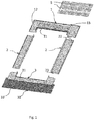
Fig. 1 shows a kit of parts according to the present invention, -
Fig. 2 shows a schematically a vertical section along the sloping direction of a sloping roof and illustrates a sealing and fastening effect obtained by means of a locking strip according to the invention, -
Fig. 3 shows a first example of flashing a roof window using a kit of parts according to the invention, -
Fig. 4 shows a second example of flashing a roof window using a kit of parts according to the invention, -
Fig. 5 shows a third example of flashing a roof window using a kit of parts according to the invention, and -
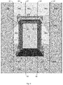
Figs. 6-9 illustrate details of the method of flashing a roof element according to the invention. -
Fig 1 . shows a kit of parts comprising an upper flashingmember 1, twoside flashing members 2, and abottom flashing member 3. The flashing members respectively have a generally L-shaped cross-section with a first leg, 11, 21, 31 configured to be arranged against a side of a roof element 6 (Fig. 2 ) and asecond leg Fig. 2 ). The kit of parts further comprises a number oflocking strips 5 of which four is shown inFig. 1 . - The kit of parts is intended for flashing a roof element mounted in a sloping roof. Inhere a
roof window 6 is used as an example of such roof element, but the invention is not limited to roof windows. Thus, roof elements as such comprise e.g. solar panels, etc. - Further, the kit of parts is intended for flashing a roof element mounted in a sloping roof with a roof covering comprising flat material, such as sheet metal or plastic, e.g. provided as
longitudinal roofing panels 41. Herein, as an example, reference is made to a roof covering comprising sheet metal,roofing panels 41 installed in the sloping direction of the roof, i.e. perpendicular to horizontal, wherebyadjacent roofing panels 41 are joined by standingseams 42. - The
second legs member 1 and theside flashing members 2 are configured to be at least in part positioned beneath the roof covering 4, whereby respectiveouter edges said edges Fig. 2 . - The
second leg 32 of thebottom flashing member 3 includes, in a manner known per se, aflexible skirt 33 configured to be at least in part positioned above the roof covering to seal between the roof element and the roof covering. - In the embodiment shown, the
locking strips 5 comprise flat pieces of material of suitable strength, such as metal or plastic, with mutually opposite, parallel,longitudinal side edges line 52, which in the shown embodiment is positioned centrally between thelongitudinal side edges locking strip 5 has a V-shaped cross-section with a concave side defining an angle of approx. 173°-178°, especially approx. 175°. -
Fig. 2 illustrates the sealing and fastening effect of the locking strips 5. ThusFig. 2 shows theroof window 6 mounted in the sloping roof with the roof covering 4 comprising theroofing panels 41, that are mutually joined by standingseams 42. Theupper flashing member 1 has itsfirst leg 11 positioned against the side of thewindow frame 61 and thesecond leg 12 is extending below theroofing panel 41 positioned next to and above thewindow 6. - A
first locking strip 105 is mounted on thesecond leg 12 of theupper flashing member 1 to extend in a horizontal direction parallel to thefirst leg 11. A first,longitudinal side edge 51a is in abutment against the surface of thesecond leg 12. Due to the mounted position of thefirst locking strip 105, the first,longitudinal side edge 51a is an upper, longitudinal side edge. A correspondingly lower, second,longitudinal side edge 51b is raised from the surface of thesecond leg 12 due to the V-shape of thelocking strip 105. Thereby the second,longitudinal side edge 51b extends at an angle α of 2°-7°, in thepresent embodiment 5°, relative to the surface of thesecond leg 12. Thelocking strip 105 is sealed and adhered, e.g. by means of an adhesive sealing material, such as butyl, to the surface of thesecond leg 12, possibly prior to the mounting of theupper flashing member 1, and is subsequently fastened to the underlying carrying structure of the roof by means of e.g. screws or nails (not shown). Thelower edge 43 of theroofing panel 41 above theroof window 6 is bent to engage with the raised, second,longitudinal side edge 51b of thelocking strip 105. - Thus, the locking
strip 105 provides for fastening, in a convenient manner, theedge 43 of theroofing panel 41 to the subjacent surface, i.e. the upper surface of thesecond leg 12 of theupper flashing member 1. In a corresponding manner the locking strip might provide or fastening an edge of a roofing panel to an upper surface of e.g. another roofing panel adjacent the roof element. - The
locking strip 105 further provides for sealing against water on the roof that in bad weather conditions might migrate up below the edge of theroofing panel 41. -
Fig. 3 shows the arrangement of locking strips in a first example of flashing aroof window 6. In this firstexample standing seams 42 betweenadjacent roofing panels 41 are positioned close to theroof window 6. - In this first example, initially a
full roofing panel 141 is mounted at one side of theroof window 6, in the present example to the left of theroof window 6 as seen inFig. 3 , that shows theroof window 6 seen from the outside in a direction of view perpendicular to the surface of the roof covering. Nextlower roofing panels 241 are adapted in their longitudinal direction having regard to theroof window 6, and thelower roofing panels 241 are mounted. Thebottom flashing member 3 is mounted. Possibly the ends of thesecond leg 32 and thus of theskirt 33 are cut to adapt the horizontal length of thebottom flashing member 3 to the distance between the adjacent standing seams 42. Side roofing panels 341 (shown transparent) are cut to appropriate size and are mounted on either side of theroof window 6 together with theside flashing members 2. - The
upper flashing member 1 is then mounted. Thefirst locking strip 105 is mounted either after theupper flashing member 1 is mounted or at any time before theupper flashing member 1 is mounted. Second locking strips 205 are cut to length and oblique to fit the angle of mounting relative the sloping direction of the roof represented by the direction of the standingseams 41 which are vertical as seen iFig. 3 . The second locking strips 205 are, as shown, overlapping the ends of thefirst locking strip 105 and are extending to the vicinity of theadjacent standing seams 42 to allow any water to pass down between the second locking strips 205 and the adjacent standing seams 42. The first andsecond locking strip - Subsequently, upper roofing panels 441 (shown transparent) to be mounted above the
roof window 6 are cut to appropriate size and theirlower edges 43 are folded and engaged with the first and second locking strips 105 and 205 during mounting of theupper roofing panels 441. Thereafter the nextfull roofing panel 541 is mounted. Alternatively, the nextfull roofing panel 541 is mounted at an earlier stage, e.g. before theupper flashing member 1 is mounted. -
Fig. 4 shows the arrangement of locking strips in a second example of flashing aroof window 6. In this secondexample standing seams 42 betweenadjacent roofing panels 41 are positioned at a great distance from theroof window 6. - In this second example, initially a
full roofing panel 141 is mounted at one side of theroof window 6, in the present example to the left of theroof window 6 as seen inFig. 4 , that shows theroof window 6 seen from the outside in a direction of view perpendicular to the surface of the roof covering. Nextlower roofing panels 241 are adapted in their longitudinal direction having regard to theroof window 6, and thelower roofing panels 241 are mounted. Thebottom flashing member 3 is mounted. Then bottom locking strips 305 are mounted on the surface of the respectivelower roofing panels 241 to extend from lower corners of theskirt 33 of thebottom flashing member 3 in a downwards oblique direction to the vicinity of the adjacent standing seams 42. - Side roofing panels 341 (shown transparent) are cut to appropriate size and are mounted on either side of the
roof window 6 together with theside flashing members 2. Lower edges 343 of theside roofing panels 341 are folded and are engaged with the bottom locking strips 305 during the mounting of theside roofing panels 341. Due to the engagement between the bottom locking strips 305 and the lower edges of theside roofing panels 341, the adjacent ends of theskirt 33 are held in contact with the subjacentlower roofing panels 241 thus assisting keeping the skirt from flapping in windy weather conditions. - The
upper flashing member 1 is then mounted. Thefirst locking strip 105 is mounted either after theupper flashing member 1 is mounted or at any time before theupper flashing member 1 is mounted. Second locking strips 205 are cut to length and oblique to fit the angle of mounting relative the sloping direction of the roof represented by the direction of the standingseams 41 which are vertical as seen iFig. 4 . The second locking strips 205 are, as shown, overlapping the ends of thefirst locking strip 105 and the second locking strips 205 are, as the bottom locking strips 305, extending to the vicinity of theadjacent standing seams 41 to allow any water to pass down between the second locking strips 205 and the adjacent standing seams 42. The first, second, andbottom locking strip - Subsequently, upper roofing panels 441 (shown transparent) to be mounted above the
roof window 6 are cut to appropriate size and theirlower edges 43 are folded and engaged with the first and second locking strips 105 and 205 during mounting of theupper roofing panels 441. Thereafter the nextfull roofing panel 541 is mounted. Alternatively, the nextfull roofing panel 541 is mounted at an earlier stage, e.g. before theupper flashing member 1 is mounted. -
Fig. 5 shows the arrangement of locking strips in a third example of flashing aroof window 6. In this thirdexample standing seams 42 betweenadjacent roofing panels 41 are, like in the second example, positioned at a great distance from theroof window 6. - In this third example, initially a
full roofing panel 141 is mounted at one side of theroof window 6, in the present example to the left of theroof window 6 as seen inFig. 5 , that shows theroof window 6 seen from the outside in a direction of view perpendicular to the surface of the roof covering. Nextlower roofing panels 241 are adapted in their longitudinal direction having regard to theroof window 6, and thelower roofing panels 241 are mounted. Thebottom flashing member 3 is mounted. Then bottom locking strips 305 are mounted on the surface of the respectivelower roofing panels 241 to extend from lower corners of theskirt 33 of thebottom flashing member 3 in a horizontal direction to the vicinity of the adjacent standing seams 42. - Side roofing panels 341 (shown transparent) are cut to appropriate size and are mounted on either side of the
roof window 6 together with theside flashing members 2. Lower edges 343 of theside roofing panels 341 are folded and are engaged with the bottom locking strips 305 during the mounting of theside roofing panels 341. Due to the engagement between the bottom locking strips 305 and the lower edges of theside roofing panels 341, the adjacent ends of theskirt 33 are held in contact with the subjacentlower roofing panels 241 thus assisting keeping the skirt from flapping in windy weather conditions. - The
upper flashing member 1 is then mounted. Thefirst locking strip 105 is mounted either after theupper flashing member 1 is mounted or at any time before theupper flashing member 1 is mounted. Second locking strips 205 are cut to length to extend to a lower edge of theupper flashing member 1. The second locking strips 205 are, as shown, overlapping the ends of thefirst locking strip 105. - Third locking strips 405 are cut to length and mounted to extend from the lower ends of the second locking strips 205 and, as the bottom locking strips 305, to the vicinity of the
adjacent standing seams 41 to allow any water to pass down between the third locking strips 405 and the adjacent standing seams 42. The first, second, bottom andthird locking strip - Subsequently, upper roofing panels 441 (shown transparent) to be mounted above the
roof window 6 are cut to appropriate size and theirlower edges 43 are folded and engaged with the first, second and third locking strips 105, 205 and 405 during mounting of theupper roofing panels 441. Thereafter the nextfull roofing panel 541 is mounted. Alternatively, the nextfull roofing panel 541 is mounted at an earlier stage, e.g. before theupper flashing member 1 is mounted. -
Figs. 6-9 show different stages in the mounting of the second locking strips 205 and the possible third locking strips 405 and theupper roofing panels 441 attached thereto. - Thus
Fig. 6 shows i.a. theroof window 6, theside roofing panels 341, theupper flashing member 1 with thefirst locking strip 105 attached thereto and an outline of the intended positions of the second locking strips 205 and athird locking strip 405, which in the embodiment shown inFigs. 6-9 is intended only at the right side of theroof window 6 due to the respective distances between theroof window 6 and the adjacent seams 42. - In
Fig. 7 the second locking strips 205 and thethird locking strip 405 have been cut to their intended sizes and are indicated to be mounted by means of a strip of adhesive sealing material 7 (e.g. butyl) and screws 8. - In
Fig. 8 the subsequently marking ofupper roofing panels 441, intended for engaging with the first, the second and third locking strips 105, 205, 405, with the positions of said first, second and third locking strips 105, 205, 405 is made, e.g. using apencil 9, and, as indicated inFig. 9 the markedupper roofing panels 441 are cut to an oversize and cut at corners to provide for folding, as indicated by arrows inFig. 9 , to provide the folded lower edges 43. Theupper roofing panels 441 are then mounted whereby the foldedlower edges 43 engage with the respective first, second and third locking strips 105, 205, 405 as indicated inFig. 2 and inbox 10 inFig. 8 .
Claims (11)
- A kit of parts for flashing a roof element (6), such as a roof window, in a sloping roof with a roof covering (4) comprising flat roofing panels (41), possibly of sheet metal, comprising an upper flashing member (1), two side flashing members (2) and a bottom flashing member (3), said flashing members respectively having a generally L-shaped cross-section with a first leg (11, 21, 31) configured to be arranged against a side of the roof element (6) and a second leg (12, 22, 32) configured to extend parallel to a plane of the roof covering (4), whereby the second legs (12, 22) of the upper flashing member (1) and the side flashing members (2) are configured to be at least in part positioned beneath the roof covering (4) and the bottom flashing member (3) comprises a second leg (32), possibly including a flexible skirt (33), configured to be at least in part positioned above the roof covering (4) to seal between the roof element (6) and the roof covering (4), characterized by a locking strip (5, 105, 205, 305, 405) configured to engage with a folded edge (43, 343) of the roof covering (4), said locking strip (5, 105, 205, 305, 405) being elongate with two mutually opposite, longitudinal side edges (51a, 51b) and having a single bend in a single direction between the two longitudinal side edges (51a, 51b) whereby one of the longitudinal side edges (51b) is raised from a mounting surface, such as the surface of the second leg (12) of a flashing member (1) or of a roofing panel (241, 341), when the locking strip (5, 105, 205, 305, 405) is positioned with the opposite, longitudinal side edge (51a) against said mounting surface, a concave side of the locking strip facing away from said mounting surface.
- A kit of part according to claim 1, characterized by comprising at least three locking strips (105, 205).
- A kit of parts according to claim 1 or 2, characterized in that the mutually opposite, longitudinal side edges (51a, 51b) of the locking strip are parallel.
- A kit of parts according to any one of claims 1 to 3, characterized in that the locking strip (5) has a V-shaped cross-section.
- A kit of parts according to any one of claims 1 to 4, characterized in that the single bend extends centrally (52) between the mutually opposite, longitudinal side edges (51a, 51b) of the locking strip.
- A kit of parts according to any one of claims 1 to 5, characterized in that the concave side of the locking strip (5) due to the bend defines an angle of approx. 173°-178°, especially approx. 175°.
- A method of flashing a roof element (6), such as a roof window, in a sloping roof with a roof covering (4) comprising flat roofing panels (41), possibly of sheet metal, using a kit of parts according to any one of claims 1 to 6, wherein the method comprises the steps of:a) mounting a full roofing panel (141) at a first side of the roof element (6),b) mounting at least one lower roofing panel (241) below the roof element (6),c) mounting the bottom flashing member (3),d) mounting side roofing panels (341) on either side of the roof element (6) together with the side flashing members (2),e) mounting the upper flashing member (1), andf) mounting at least one upper roofing panel (441) above the roof element (6),
characterized in that between at least one of steps c) and d) and steps e) and f) at least one locking strip (5) is mounted for engagement with a folded lower edge (43, 343) of the subsequently mounted roofing panel (341, 441). - A method according to claim 7, characterized in that three locking strips (105, 205) are mounted at an upper end of the roof element (6) between steps e) and f) whereby a first locking strip (105) is mounted above the roof element (6) in a horizontal position and two second locking strips (205) are mounted at either end of the first locking strip (105) to extend downwards at oblique angles past upper corners of the roof element (6).
- A method according to claim 8, characterized in that third locking strips (405) are mounted in extension of the second locking strips (205) at a different angle closer to horizontal than said oblique angles or horizontally to extend towards seams (42) next to the roof element between joined roofing panels (141, 441; 441, 541).
- A method according to any one of claims 7 to 9, characterized in that additional locking strips (305) are mounted at a lower end of the roof element (6) between steps c) and d), whereby the additional locking strips (305) are mounted to extend from respective ends of a horizontal lower edge of the second leg (32) of the bottom flashing member (3), said additional locking strips (305) thereby extending in a horizontal direction or an obliquely downward direction towards seams (42) next to the roof element (6) between joined roofing panels (141, 441; 441, 541).
- A method according to claim 8, characterized in that the locking strips (205, 305) extending towards seams next to the roof element are extending to the vicinity of said seams (42).
Priority Applications (1)
| Application Number | Priority Date | Filing Date | Title |
|---|---|---|---|
| PL19173060T PL3567180T3 (en) | 2018-05-07 | 2019-05-07 | A kit of parts for flashing a roof element and a method of flashing a roof element using such kit of parts |
Applications Claiming Priority (1)
| Application Number | Priority Date | Filing Date | Title |
|---|---|---|---|
| DKPA201870279A DK180221B1 (en) | 2018-05-07 | 2018-05-07 | A kit of parts for flashing a roof element and a method of flashing a roof element using such kit of parts |
Publications (2)
| Publication Number | Publication Date |
|---|---|
| EP3567180A1 true EP3567180A1 (en) | 2019-11-13 |
| EP3567180B1 EP3567180B1 (en) | 2021-09-08 |
Family
ID=66448400
Family Applications (1)
| Application Number | Title | Priority Date | Filing Date |
|---|---|---|---|
| EP19173060.5A Active EP3567180B1 (en) | 2018-05-07 | 2019-05-07 | A kit of parts for flashing a roof element and a method of flashing a roof element using such kit of parts |
Country Status (4)
| Country | Link |
|---|---|
| EP (1) | EP3567180B1 (en) |
| DK (1) | DK180221B1 (en) |
| HU (1) | HUE056483T2 (en) |
| PL (2) | PL127399U1 (en) |
Cited By (1)
| Publication number | Priority date | Publication date | Assignee | Title |
|---|---|---|---|---|
| EP4442925A1 (en) * | 2023-04-05 | 2024-10-09 | VKR Holding A/S | A flashing assembly comprising a top flashing arrangement, a roof element system comprising such a flashing assembly, and a method of manufacturing a flashing assembly |
Citations (2)
| Publication number | Priority date | Publication date | Assignee | Title |
|---|---|---|---|---|
| US4951431A (en) * | 1989-08-07 | 1990-08-28 | Sweers Ronald L | Chimney and wall flashing system |
| US20030208964A1 (en) * | 2002-05-07 | 2003-11-13 | Batt Dennis J. | Flashing assembly |
-
2018
- 2018-05-07 DK DKPA201870279A patent/DK180221B1/en not_active IP Right Cessation
- 2018-06-05 PL PL12739918U patent/PL127399U1/en unknown
-
2019
- 2019-05-07 HU HUE19173060A patent/HUE056483T2/en unknown
- 2019-05-07 EP EP19173060.5A patent/EP3567180B1/en active Active
- 2019-05-07 PL PL19173060T patent/PL3567180T3/en unknown
Patent Citations (2)
| Publication number | Priority date | Publication date | Assignee | Title |
|---|---|---|---|---|
| US4951431A (en) * | 1989-08-07 | 1990-08-28 | Sweers Ronald L | Chimney and wall flashing system |
| US20030208964A1 (en) * | 2002-05-07 | 2003-11-13 | Batt Dennis J. | Flashing assembly |
Non-Patent Citations (1)
| Title |
|---|
| VELUX: "EDL Click Roof", VELUX. INSTALLATION INSTRUCTIONS, 2016, XP055595433, Retrieved from the Internet <URL:http://weshare.velux.com/A/We%20Share/83269?encoding=UTF-8> [retrieved on 20190611] * |
Cited By (1)
| Publication number | Priority date | Publication date | Assignee | Title |
|---|---|---|---|---|
| EP4442925A1 (en) * | 2023-04-05 | 2024-10-09 | VKR Holding A/S | A flashing assembly comprising a top flashing arrangement, a roof element system comprising such a flashing assembly, and a method of manufacturing a flashing assembly |
Also Published As
| Publication number | Publication date |
|---|---|
| DK201870279A1 (en) | 2019-12-05 |
| HUE056483T2 (en) | 2022-02-28 |
| PL127399U1 (en) | 2019-11-18 |
| EP3567180B1 (en) | 2021-09-08 |
| PL3567180T3 (en) | 2022-01-17 |
| DK180221B1 (en) | 2020-08-21 |
Similar Documents
| Publication | Publication Date | Title |
|---|---|---|
| US5522189A (en) | Flashing for roof elements | |
| US6966157B1 (en) | Standing seam skylight | |
| US7937900B1 (en) | Metal roof retrofit skylight | |
| US20090031640A1 (en) | Roof Flashing Connections | |
| US20040139669A1 (en) | Flashing component for a roof window assembly | |
| JP4421775B2 (en) | Rain retaining member and rain retaining frame for roof penetrating buildings | |
| HU223750B1 (en) | Adjustable roof flashing and flashing kit | |
| US9334652B2 (en) | Paneling system | |
| ES2951662T3 (en) | Covering device | |
| DK179519B1 (en) | A roof window installed in an inclined roof structure with a flashing assembly and a method for weather proofing a roof window | |
| EP0756659B1 (en) | A flashing for roof elements | |
| CN102561605A (en) | A flashing member having a compensation member, a kit including the flashing menber and a method for mounting a flashing for a roof window | |
| CZ20002279A3 (en) | Insulation frame | |
| CN101578417B (en) | Sliding roof seam construction | |
| PL224719B1 (en) | A set of constructions penetrating the roof with flashing | |
| US3967423A (en) | Skylight system | |
| DK150464B (en) | SEALING PART FOR SEALING A JOINT BETWEEN ONE OF THE ROOF COVERED PLATES AND A ROOF WINDOW | |
| EP3567180B1 (en) | A kit of parts for flashing a roof element and a method of flashing a roof element using such kit of parts | |
| CZ288228B6 (en) | Roof structure, fitting collar for sealingly joining said roof structure and a method for the manufacture of said fitting collar | |
| CN1665997B (en) | Sheet-like flashing member and flashing kit | |
| JPH02304152A (en) | Roof panel fitted with eaves back cradling | |
| JP7667974B2 (en) | Waterproofing materials for window frames | |
| CA1039920A (en) | Roof panel | |
| CN101886433B (en) | Waterproof member and waterproof structure on top of wall opening for steel structure building | |
| JPH053623Y2 (en) |
Legal Events
| Date | Code | Title | Description |
|---|---|---|---|
| PUAI | Public reference made under article 153(3) epc to a published international application that has entered the european phase |
Free format text: ORIGINAL CODE: 0009012 |
|
| STAA | Information on the status of an ep patent application or granted ep patent |
Free format text: STATUS: THE APPLICATION HAS BEEN PUBLISHED |
|
| AK | Designated contracting states |
Kind code of ref document: A1 Designated state(s): AL AT BE BG CH CY CZ DE DK EE ES FI FR GB GR HR HU IE IS IT LI LT LU LV MC MK MT NL NO PL PT RO RS SE SI SK SM TR |
|
| AX | Request for extension of the european patent |
Extension state: BA ME |
|
| STAA | Information on the status of an ep patent application or granted ep patent |
Free format text: STATUS: REQUEST FOR EXAMINATION WAS MADE |
|
| 17P | Request for examination filed |
Effective date: 20200513 |
|
| RBV | Designated contracting states (corrected) |
Designated state(s): AL AT BE BG CH CY CZ DE DK EE ES FI FR GB GR HR HU IE IS IT LI LT LU LV MC MK MT NL NO PL PT RO RS SE SI SK SM TR |
|
| GRAP | Despatch of communication of intention to grant a patent |
Free format text: ORIGINAL CODE: EPIDOSNIGR1 |
|
| STAA | Information on the status of an ep patent application or granted ep patent |
Free format text: STATUS: GRANT OF PATENT IS INTENDED |
|
| INTG | Intention to grant announced |
Effective date: 20210309 |
|
| GRAJ | Information related to disapproval of communication of intention to grant by the applicant or resumption of examination proceedings by the epo deleted |
Free format text: ORIGINAL CODE: EPIDOSDIGR1 |
|
| STAA | Information on the status of an ep patent application or granted ep patent |
Free format text: STATUS: REQUEST FOR EXAMINATION WAS MADE |
|
| GRAP | Despatch of communication of intention to grant a patent |
Free format text: ORIGINAL CODE: EPIDOSNIGR1 |
|
| STAA | Information on the status of an ep patent application or granted ep patent |
Free format text: STATUS: GRANT OF PATENT IS INTENDED |
|
| INTC | Intention to grant announced (deleted) | ||
| INTG | Intention to grant announced |
Effective date: 20210609 |
|
| GRAS | Grant fee paid |
Free format text: ORIGINAL CODE: EPIDOSNIGR3 |
|
| GRAA | (expected) grant |
Free format text: ORIGINAL CODE: 0009210 |
|
| STAA | Information on the status of an ep patent application or granted ep patent |
Free format text: STATUS: THE PATENT HAS BEEN GRANTED |
|
| AK | Designated contracting states |
Kind code of ref document: B1 Designated state(s): AL AT BE BG CH CY CZ DE DK EE ES FI FR GB GR HR HU IE IS IT LI LT LU LV MC MK MT NL NO PL PT RO RS SE SI SK SM TR |
|
| REG | Reference to a national code |
Ref country code: GB Ref legal event code: FG4D |
|
| REG | Reference to a national code |
Ref country code: CH Ref legal event code: EP Ref country code: AT Ref legal event code: REF Ref document number: 1428729 Country of ref document: AT Kind code of ref document: T Effective date: 20210915 |
|
| REG | Reference to a national code |
Ref country code: DE Ref legal event code: R096 Ref document number: 602019007454 Country of ref document: DE |
|
| REG | Reference to a national code |
Ref country code: IE Ref legal event code: FG4D |
|
| REG | Reference to a national code |
Ref country code: LT Ref legal event code: MG9D |
|
| REG | Reference to a national code |
Ref country code: NL Ref legal event code: MP Effective date: 20210908 |
|
| REG | Reference to a national code |
Ref country code: SK Ref legal event code: T3 Ref document number: E 38636 Country of ref document: SK |
|
| PG25 | Lapsed in a contracting state [announced via postgrant information from national office to epo] |
Ref country code: LT Free format text: LAPSE BECAUSE OF FAILURE TO SUBMIT A TRANSLATION OF THE DESCRIPTION OR TO PAY THE FEE WITHIN THE PRESCRIBED TIME-LIMIT Effective date: 20210908 Ref country code: BG Free format text: LAPSE BECAUSE OF FAILURE TO SUBMIT A TRANSLATION OF THE DESCRIPTION OR TO PAY THE FEE WITHIN THE PRESCRIBED TIME-LIMIT Effective date: 20211208 Ref country code: HR Free format text: LAPSE BECAUSE OF FAILURE TO SUBMIT A TRANSLATION OF THE DESCRIPTION OR TO PAY THE FEE WITHIN THE PRESCRIBED TIME-LIMIT Effective date: 20210908 Ref country code: NO Free format text: LAPSE BECAUSE OF FAILURE TO SUBMIT A TRANSLATION OF THE DESCRIPTION OR TO PAY THE FEE WITHIN THE PRESCRIBED TIME-LIMIT Effective date: 20211208 Ref country code: FI Free format text: LAPSE BECAUSE OF FAILURE TO SUBMIT A TRANSLATION OF THE DESCRIPTION OR TO PAY THE FEE WITHIN THE PRESCRIBED TIME-LIMIT Effective date: 20210908 Ref country code: ES Free format text: LAPSE BECAUSE OF FAILURE TO SUBMIT A TRANSLATION OF THE DESCRIPTION OR TO PAY THE FEE WITHIN THE PRESCRIBED TIME-LIMIT Effective date: 20210908 Ref country code: SE Free format text: LAPSE BECAUSE OF FAILURE TO SUBMIT A TRANSLATION OF THE DESCRIPTION OR TO PAY THE FEE WITHIN THE PRESCRIBED TIME-LIMIT Effective date: 20210908 Ref country code: RS Free format text: LAPSE BECAUSE OF FAILURE TO SUBMIT A TRANSLATION OF THE DESCRIPTION OR TO PAY THE FEE WITHIN THE PRESCRIBED TIME-LIMIT Effective date: 20210908 |
|
| PG25 | Lapsed in a contracting state [announced via postgrant information from national office to epo] |
Ref country code: LV Free format text: LAPSE BECAUSE OF FAILURE TO SUBMIT A TRANSLATION OF THE DESCRIPTION OR TO PAY THE FEE WITHIN THE PRESCRIBED TIME-LIMIT Effective date: 20210908 Ref country code: GR Free format text: LAPSE BECAUSE OF FAILURE TO SUBMIT A TRANSLATION OF THE DESCRIPTION OR TO PAY THE FEE WITHIN THE PRESCRIBED TIME-LIMIT Effective date: 20211209 |
|
| REG | Reference to a national code |
Ref country code: HU Ref legal event code: AG4A Ref document number: E056483 Country of ref document: HU |
|
| PG25 | Lapsed in a contracting state [announced via postgrant information from national office to epo] |
Ref country code: IS Free format text: LAPSE BECAUSE OF FAILURE TO SUBMIT A TRANSLATION OF THE DESCRIPTION OR TO PAY THE FEE WITHIN THE PRESCRIBED TIME-LIMIT Effective date: 20220108 Ref country code: SM Free format text: LAPSE BECAUSE OF FAILURE TO SUBMIT A TRANSLATION OF THE DESCRIPTION OR TO PAY THE FEE WITHIN THE PRESCRIBED TIME-LIMIT Effective date: 20210908 Ref country code: PT Free format text: LAPSE BECAUSE OF FAILURE TO SUBMIT A TRANSLATION OF THE DESCRIPTION OR TO PAY THE FEE WITHIN THE PRESCRIBED TIME-LIMIT Effective date: 20220110 Ref country code: NL Free format text: LAPSE BECAUSE OF FAILURE TO SUBMIT A TRANSLATION OF THE DESCRIPTION OR TO PAY THE FEE WITHIN THE PRESCRIBED TIME-LIMIT Effective date: 20210908 Ref country code: EE Free format text: LAPSE BECAUSE OF FAILURE TO SUBMIT A TRANSLATION OF THE DESCRIPTION OR TO PAY THE FEE WITHIN THE PRESCRIBED TIME-LIMIT Effective date: 20210908 Ref country code: AL Free format text: LAPSE BECAUSE OF FAILURE TO SUBMIT A TRANSLATION OF THE DESCRIPTION OR TO PAY THE FEE WITHIN THE PRESCRIBED TIME-LIMIT Effective date: 20210908 |
|
| REG | Reference to a national code |
Ref country code: DE Ref legal event code: R097 Ref document number: 602019007454 Country of ref document: DE |
|
| PLBE | No opposition filed within time limit |
Free format text: ORIGINAL CODE: 0009261 |
|
| STAA | Information on the status of an ep patent application or granted ep patent |
Free format text: STATUS: NO OPPOSITION FILED WITHIN TIME LIMIT |
|
| PG25 | Lapsed in a contracting state [announced via postgrant information from national office to epo] |
Ref country code: DK Free format text: LAPSE BECAUSE OF FAILURE TO SUBMIT A TRANSLATION OF THE DESCRIPTION OR TO PAY THE FEE WITHIN THE PRESCRIBED TIME-LIMIT Effective date: 20210908 |
|
| 26N | No opposition filed |
Effective date: 20220609 |
|
| PG25 | Lapsed in a contracting state [announced via postgrant information from national office to epo] |
Ref country code: SI Free format text: LAPSE BECAUSE OF FAILURE TO SUBMIT A TRANSLATION OF THE DESCRIPTION OR TO PAY THE FEE WITHIN THE PRESCRIBED TIME-LIMIT Effective date: 20210908 |
|
| REG | Reference to a national code |
Ref country code: AT Ref legal event code: UEP Ref document number: 1428729 Country of ref document: AT Kind code of ref document: T Effective date: 20210908 |
|
| REG | Reference to a national code |
Ref country code: CH Ref legal event code: PL |
|
| PG25 | Lapsed in a contracting state [announced via postgrant information from national office to epo] |
Ref country code: MC Free format text: LAPSE BECAUSE OF FAILURE TO SUBMIT A TRANSLATION OF THE DESCRIPTION OR TO PAY THE FEE WITHIN THE PRESCRIBED TIME-LIMIT Effective date: 20210908 Ref country code: LU Free format text: LAPSE BECAUSE OF NON-PAYMENT OF DUE FEES Effective date: 20220507 Ref country code: LI Free format text: LAPSE BECAUSE OF NON-PAYMENT OF DUE FEES Effective date: 20220531 Ref country code: IT Free format text: LAPSE BECAUSE OF FAILURE TO SUBMIT A TRANSLATION OF THE DESCRIPTION OR TO PAY THE FEE WITHIN THE PRESCRIBED TIME-LIMIT Effective date: 20210908 Ref country code: CH Free format text: LAPSE BECAUSE OF NON-PAYMENT OF DUE FEES Effective date: 20220531 |
|
| PG25 | Lapsed in a contracting state [announced via postgrant information from national office to epo] |
Ref country code: IE Free format text: LAPSE BECAUSE OF NON-PAYMENT OF DUE FEES Effective date: 20220507 |
|
| PG25 | Lapsed in a contracting state [announced via postgrant information from national office to epo] |
Ref country code: MK Free format text: LAPSE BECAUSE OF FAILURE TO SUBMIT A TRANSLATION OF THE DESCRIPTION OR TO PAY THE FEE WITHIN THE PRESCRIBED TIME-LIMIT Effective date: 20210908 Ref country code: CY Free format text: LAPSE BECAUSE OF FAILURE TO SUBMIT A TRANSLATION OF THE DESCRIPTION OR TO PAY THE FEE WITHIN THE PRESCRIBED TIME-LIMIT Effective date: 20210908 |
|
| PG25 | Lapsed in a contracting state [announced via postgrant information from national office to epo] |
Ref country code: TR Free format text: LAPSE BECAUSE OF FAILURE TO SUBMIT A TRANSLATION OF THE DESCRIPTION OR TO PAY THE FEE WITHIN THE PRESCRIBED TIME-LIMIT Effective date: 20210908 |
|
| PG25 | Lapsed in a contracting state [announced via postgrant information from national office to epo] |
Ref country code: MT Free format text: LAPSE BECAUSE OF FAILURE TO SUBMIT A TRANSLATION OF THE DESCRIPTION OR TO PAY THE FEE WITHIN THE PRESCRIBED TIME-LIMIT Effective date: 20210908 |
|
| PGFP | Annual fee paid to national office [announced via postgrant information from national office to epo] |
Ref country code: DE Payment date: 20250402 Year of fee payment: 7 Ref country code: PL Payment date: 20250414 Year of fee payment: 7 |
|
| PGFP | Annual fee paid to national office [announced via postgrant information from national office to epo] |
Ref country code: HU Payment date: 20250429 Year of fee payment: 7 |
|
| PGFP | Annual fee paid to national office [announced via postgrant information from national office to epo] |
Ref country code: BE Payment date: 20250410 Year of fee payment: 7 |
|
| PGFP | Annual fee paid to national office [announced via postgrant information from national office to epo] |
Ref country code: FR Payment date: 20250422 Year of fee payment: 7 |
|
| PGFP | Annual fee paid to national office [announced via postgrant information from national office to epo] |
Ref country code: RO Payment date: 20250415 Year of fee payment: 7 Ref country code: AT Payment date: 20250425 Year of fee payment: 7 |
|
| PGFP | Annual fee paid to national office [announced via postgrant information from national office to epo] |
Ref country code: SK Payment date: 20250416 Year of fee payment: 7 |
|
| PGFP | Annual fee paid to national office [announced via postgrant information from national office to epo] |
Ref country code: CZ Payment date: 20250423 Year of fee payment: 7 |
|
| PGFP | Annual fee paid to national office [announced via postgrant information from national office to epo] |
Ref country code: GB Payment date: 20260312 Year of fee payment: 8 |