EP3566946B1 - Seat assembly having a deployable headrest - Google Patents
Seat assembly having a deployable headrest Download PDFInfo
- Publication number
- EP3566946B1 EP3566946B1 EP19173450.8A EP19173450A EP3566946B1 EP 3566946 B1 EP3566946 B1 EP 3566946B1 EP 19173450 A EP19173450 A EP 19173450A EP 3566946 B1 EP3566946 B1 EP 3566946B1
- Authority
- EP
- European Patent Office
- Prior art keywords
- headrest
- backrest
- seat assembly
- stowed position
- support beam
- Prior art date
- Legal status (The legal status is an assumption and is not a legal conclusion. Google has not performed a legal analysis and makes no representation as to the accuracy of the status listed.)
- Active
Links
Images


Classifications
-
- B—PERFORMING OPERATIONS; TRANSPORTING
- B64—AIRCRAFT; AVIATION; COSMONAUTICS
- B64D—EQUIPMENT FOR FITTING IN OR TO AIRCRAFT; FLIGHT SUITS; PARACHUTES; ARRANGEMENT OR MOUNTING OF POWER PLANTS OR PROPULSION TRANSMISSIONS IN AIRCRAFT
- B64D11/00—Passenger or crew accommodation; Flight-deck installations not otherwise provided for
- B64D11/06—Arrangements of seats, or adaptations or details specially adapted for aircraft seats
- B64D11/0638—Arrangements of seats, or adaptations or details specially adapted for aircraft seats with foldable tables, trays or cup holders
-
- B—PERFORMING OPERATIONS; TRANSPORTING
- B64—AIRCRAFT; AVIATION; COSMONAUTICS
- B64D—EQUIPMENT FOR FITTING IN OR TO AIRCRAFT; FLIGHT SUITS; PARACHUTES; ARRANGEMENT OR MOUNTING OF POWER PLANTS OR PROPULSION TRANSMISSIONS IN AIRCRAFT
- B64D11/00—Passenger or crew accommodation; Flight-deck installations not otherwise provided for
- B64D11/06—Arrangements of seats, or adaptations or details specially adapted for aircraft seats
- B64D11/0639—Arrangements of seats, or adaptations or details specially adapted for aircraft seats with features for adjustment or converting of seats
- B64D11/0642—Adjustable headrests
-
- B—PERFORMING OPERATIONS; TRANSPORTING
- B60—VEHICLES IN GENERAL
- B60N—SEATS SPECIALLY ADAPTED FOR VEHICLES; VEHICLE PASSENGER ACCOMMODATION NOT OTHERWISE PROVIDED FOR
- B60N2/00—Seats specially adapted for vehicles; Arrangement or mounting of seats in vehicles
- B60N2/80—Head-rests
- B60N2/806—Head-rests movable or adjustable
- B60N2/874—Head-rests movable or adjustable movable to an inoperative or stowed position
-
- B—PERFORMING OPERATIONS; TRANSPORTING
- B60—VEHICLES IN GENERAL
- B60N—SEATS SPECIALLY ADAPTED FOR VEHICLES; VEHICLE PASSENGER ACCOMMODATION NOT OTHERWISE PROVIDED FOR
- B60N3/00—Arrangements or adaptations of other passenger fittings, not otherwise provided for
- B60N3/001—Arrangements or adaptations of other passenger fittings, not otherwise provided for of tables or trays
- B60N3/002—Arrangements or adaptations of other passenger fittings, not otherwise provided for of tables or trays of trays
- B60N3/004—Arrangements or adaptations of other passenger fittings, not otherwise provided for of tables or trays of trays of foldable trays mounted on the back-rest
Definitions
- Embodiments of the present disclosure generally relate to interior cabins within vehicles, such as commercial aircraft, and, more particularly, to seat assemblies within interior cabins of vehicles.
- a cockpit is generally separated from a passenger cabin, which may include a first class section, a business class section, and a coach section.
- the passenger cabin may also include one or more work areas for flight personnel, such as galleys, which may include food and beverage storage structures.
- One or more aisles pass through the passenger cabin and connect each of the passenger sections to one or more paths and/or one or more doors of the aircraft.
- Passenger seats are positioned within the interior cabin. During a flight, particularly a long haul flight, a passenger seated within a seat may decide to rest. A rear portion of a head of a passenger may be supported on a front of a backrest.
- the passenger may prefer to rest in a different position.
- the passenger may prefer to rest in a forward position, such that the head of the passenger abuts into a rear surface of a backrest of a seat in front of the passenger.
- the passenger may support the head over a deployed tray table.
- US6,619,733 in accordance with its abstract, states a passenger headrest that is platform deployable and stowable from a passenger seat.
- the platform operates as a rear headrest and is pivoted to a forward position to serve as a forward leaning face-headrest.
- the headrest includes a headrest platform that is attached to an adjustable post made of tubular construction and having a plurality of holes.
- the adjustable post is concentrically dimensioned to be slidably received by a tubular bar.
- the tubular bar has a set of holes and is pivotably attached to the passenger seat.
- a first connector secures the adjustable post and tubular bar to each other.
- the headrest is pivotable through a range of motion adjusted by a passenger, wherein the passenger selects an inclination angle.
- the inclination angle used by the passenger is established via a second connector that secures the tubular bar to the seat.
- US2012/181821 according to its abstract states a method and a device for a multi-adjustable body-rest structure suitable for use in a sitting position, including sitting positions in a multi-row seating arrangement such as those encountered on board of airplanes, busses, ferries, and trains, among other similar arrangements.
- the multi-adjustable body-rest structure is generally configured to be used for rest or sleep while leaning forward from the user seat onto the back of the seat in front of the user seat.
- the multi-adjustable body-rest structure is further configured to be folded into the back of the seat in front of the user seat when not in use.
- the multi-adjustable body-rest structure is further configured to be adjusted to a position that comfortably accommodates the head, chest, and arms of users with different body sizes.
- US2017096224 according to its abstract states an airplane seat sleeping device for providing a forwardly inclining head support that is attached or attachable to an adjacently proceeding vehicle seat, which has a seatback.
- the device includes a seatback attachment mechanism configured to be attachable to the seatback of the adjacently proceeding vehicle seat; a pillow support member; an intermediate member connecting the seatback attachment mechanism to the pillow support member; and a pillow support/receiving holding mechanism.
- a seat assembly that includes a seat cushion, a backrest, and a headrest moveably coupled to a back of the backrest.
- the headrest is configured to be moved between a stowed position in which the headrest is retained within a portion of the backrest and a deployed position in which the headrest is configured to support a passenger in a forward resting position.
- the seat assembly is defined in claim 1.
- the headrest in the stowed position may be retained within an envelope of the backrest.
- the headrest in the stowed position may be flush mounted with the back of the backrest.
- the headrest in the stowed position is retained within a reciprocal retaining chamber formed in the back of the backrest.
- the seat assembly may also include a moveable latch that securely retains the headrest in the stowed position.
- An electronic device may be secured within the back of the backrest.
- the headrest in the stowed position may extend around one or more portions of an electronic device.
- the headrest may include a padded insert.
- the padded insert may be removably secured to a retaining bracket.
- An antimacassar may be removably secured to the padded insert.
- the padded insert is configured to be radially shifted relative to a head support beam of the headrest.
- Certain embodiments of the present disclosure provide a method of forming a headrest of a seat assembly, the method is as defined in claim 11.
- Certain embodiments of the present disclosure provide a vehicle that includes an interior cabin, and a seat assembly within the interior cabin, as described herein.
- a seat assembly such as may be used within an interior cabin of a vehicle, which includes a deployable headrest.
- the headrest is moveably secured to a back of a backrest of the seat assembly.
- the headrest is configured to be moved between a stowed position and a deployed position. In the deployed position, the headrest is configured to comfortably support a passenger in a forward resting position.
- the headrest fits within an existing seat envelope.
- the headrest in the stowed position, the headrest may be flush-mounted with the backrest.
- the headrest is compact and light, and allows passengers to lean forward in a comfortable resting position.
- the headrest is deployable from the seat assembly in front of a passenger seated in another seat assembly, thereby allowing for a forward resting position.
- the headrest in the stowed position may be housed within an envelope of the backrest.
- a seat assembly that includes a backrest having an upper portion and a lower portion.
- the upper portion includes electronic device and the lower portion includes a tray table.
- the upper portion includes a deployable headrest that is rearwardly deployable such that a passenger in an adjacent row is able to utilize the deployable headrest.
- the headrest may be rotatably attached to the upper portion.
- the headrest may be semi-circumferentially located relative to the electronic device in a stowed position.
- the headrest is ergonomically adjustable when in a deployed position.
- the electronic device is an in-flight entertainment (IFE) system.
- IFE in-flight entertainment
- the headrest may include a padded portion and an antimacassar.
- the antimacassar is removable and/or replaceable.
- Certain embodiments of the present disclosure provide a method of manufacturing a seat including providing a seat with a backrest having an upper portion and a lower portion, and pivotally coupling a moveable headrest to the upper portion.
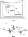
- Figure 1 illustrates a schematic block diagram of a seat assembly 100 within an interior cabin 102 of a vehicle 104, according to an embodiment of the present disclosure.
- the vehicle 104 may be a commercial aircraft, for example.
- the seat assembly 100 includes a seat cushion 106 and a backrest 108.
- a headrest 110 is moveably coupled to a rear or back 112 of the backrest 108.
- the headrest 110 is moveably coupled to an upper portion 114 of the back 112 of the backrest 108.
- the headrest 110 is configured to move in the directions of arc A between a deployed position and a stowed position relative to the backrest 108.
- the headrest 110 is pivotally coupled to the backrest 108.
- the headrest 110 In the deployed position, the headrest 110 rearwardly extends from the back 112 of the backrest 108.
- the headrest 110 In the deployed position, the headrest 110 is configured to support a head of a passenger in a forward resting position.
- the passenger is seated in an adjacent seat assembly behind the seat assembly 100. Thus, the passenger may move the headrest 110 into the deployed position and rest in the forward resting position with the headrest 110 supporting the face of the passenger.
- the headrest 110 In the stowed position, the headrest 110 is retained within the back 112 of the backrest 108. For example, the passenger may pivot the headrest 110 into a retaining chamber of the backrest 108. In the stowed position, the headrest 110 may not protrude outwardly past the back 112 of the backrest 108. Instead, the headrest 110 in the stowed position may be flush-mounted with the back 112 of the backrest 108. As such, the headrest 110 in the stowed position is not susceptible to catching or snagging articles within the interior cabin 102.
- FIG. 2 illustrates a front perspective view of a vehicle, such as an aircraft 104, according to an embodiment of the present disclosure.
- the aircraft 104 includes a propulsion system 116 that may include two turbofan engines 118, for example.
- the propulsion system 116 may include more engines 118 than shown.
- the engines 118 are carried by wings 120 of the aircraft 104.
- the engines 118 may be carried by a fuselage 122 and/or an empennage 124.
- the empennage 124 may also support horizontal stabilizers 126 and a vertical stabilizer 128.
- the fuselage 122 of the aircraft 104 defines an interior cabin, which may include a cockpit, one or more work sections (for example, galleys, personnel carry-on baggage areas, and the like), one or more passenger sections (for example, first class, business class, and coach sections), and an aft section.
- work sections for example, galleys, personnel carry-on baggage areas, and the like
- passenger sections for example, first class, business class, and coach sections
- aft section for example, first class, business class, and coach sections
- embodiments of the present disclosure may be used with various other vehicles, such as automobiles, buses, locomotives and train cars, seacraft, spacecraft, and the like.
- FIG. 3 illustrates a side view of a seat assembly 100, according to an embodiment of the present disclosure.
- the seat assembly 100 may be configured to be secured within a cabin of a vehicle, such as a commercial aircraft.
- the seat assembly 100 includes a base 130, which may include legs 132 that may be secured to tracks 134 within a cabin of a vehicle.
- the legs 132 may include fittings, fasteners, or the like that are configured to securely connect the legs 132 to the tracks 134.
- the base 130 supports a seat cushion 106 and a backrest 108. Arm rests 136 may be pivotally secured to the backrest 108.
- the headrest 110 (shown in Figure 1 ) is moveably secured to a back 112 of the backrest 108, such as through lateral arms that are pivotally secured to the backrest 108. Additionally, a tray table may also be pivotally secured to the back 112 of the backrest 108.
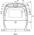
- Figure 4 illustrates a perspective rear view of the seat assembly 100, according to an embodiment of the present disclosure.
- Figure 5 illustrates a rear view of the backrest 108 of the seat assembly 100.
- the headrest 110 is shown in a stowed position.
- the headrest 110 may be flush-mounted with the backrest 108 in the stowed position.
- the headrest 110 may be contained within an envelope 150 of the backrest 108 defined by a height 152, a width 154, and a thickness 156 of the backrest 108.
- no portion of the headrest 110 may protrude outwardly past the height 152, the width 154, or the thickness 156 of the backrest 108.
- at least a portion of the headrest 110 in the stowed position may outwardly extend past at least a portion of the envelope 150 of the backrest 108.
- the headrest 110 includes a head support beam 160 that spans between opposed lateral pivot beams 162.
- the head support beam 160 extends between upper ends 164 of the lateral pivot beams 162. As shown, the head support beam 160 may be generally perpendicular to the lateral pivot beams 162.
- the headrest 110 In the stowed position, the headrest 110 is retained within a reciprocal retaining chamber 166 formed in the back 112 of the backrest 108.
- Lower ends 168 of the lateral pivot beams 162 are pivotally coupled to reciprocal structures within the back 112 of the backrest 108.
- the lower ends 168 may include pivot pins that are pivotally retained within reciprocal bearings and/or openings within the back 112 of the backrest 108, or vice versa.
- a moveable latch 170 securely retains the headrest 110 in the stowed position.
- the latch 170 may be pivoted into a release position, in which the latch 170 disengages from the head support beam 160 to allow the headrest 110 to be downwardly pivoted into a deployed position.
- the headrest 110 is moveably coupled to an upper portion 172 of the back 112 of the backrest 108.
- the headrest 110 in the stowed position may extend around one or more portions of an electronic device 174 secured within the back 112 of the backrest 108.
- the head support beam 160 is positioned over the electronic device 174, while the lateral pivot beams 162 are positioned to sides of the electronic device 174.
- the electronic device 174 may be a monitor, such as a monitor of an in-flight entertainment (IFE) system 175.
- IFE in-flight entertainment
- a tray table 180 is moveably coupled to a lower portion 176 of the back 112 of the backrest 108.
- the tray table 180 may be positioned underneath the electronic device 174. As shown in Figures 4 and 5 , the tray table is in a stowed position.
- the seat assembly 100 may not include the electronic device 174.
- the tray table 180 may extend to the upper portion 172 of the backrest 108.
- the latch 170 may be used to securely latch the headrest 110 and the tray table 180 in stowed positions.
- the headrest 110 is independent of the tray table 180 and the electronic device 174. That is, the headrest 110 is deployable without affecting the use of the tray table 180 and the electronic device 174, and vice versa.
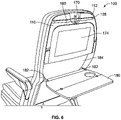
- Figure 6 illustrates a perspective rear view of the seat assembly 100 having the headrest 110 in the stowed position and the tray table 180 in a deployed position, according to an embodiment of the present disclosure.
- the latch 170 engages a rear surface of the head support beam 160 to securely retain the headrest 110 in the stowed position.
- the tray table 180 may outwardly unfold into the deployed position. Lateral pivot arms 182 may pivotally couple the tray table 180 to the lower portion 176 of the back 112 of the backrest 108.
- the tray table 180 may be folded up and pivoted into a reciprocal retaining chamber 184 underneath the electronic device 174.
- Figure 7 illustrates a perspective rear view of the seat assembly 100 having the headrest 110 in a deployed position and the tray table 180 in a deployed position, according to an embodiment of the present disclosure.
- the latch 170 is pivoted into a position such that it no longer engages the head support beam 160.
- An individual grasps a portion of the headrest 110 and pivots the headrest 110 downwardly into the deployed position, such as by the lateral pivot arms 162 downwardly pivoting in relation to the backrest 108.
- the headrest 110 rearwardly extends from the back 112 of the backrest 108.
- the headrest 110 may be held in a desired position.
- the headrest 110 and/or the backrest may include one or more of a clutched or ratcheted locking mechanism, spring-biased pins, removable pins or fasteners, clamps, and/or the like that are configured to securely lock the headrest 110 into a desired deployed position.
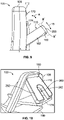
- Figure 8 illustrates a perspective rear view of the backrest 108 of the seat assembly 100 having the headrest 110 in a deployed position, according to an embodiment of the present disclosure. As shown, the headrest 110 pivots around the electronic device 174.
- the head support beam 160 includes a padded insert 200.
- the padded insert 200 may be formed of an open cell foam, and is configured to provide a comfortable, padded surface on which an individual may rest a portion of a face in a forward resting position.
- the padded insert 200 may be retained within a retaining bracket 202.
- the padded insert 200 may be removably coupled to the retaining bracket 202.
- the padded insert 200 may be a disposable unit that is configured to be replaced after one or more uses.
- the padded insert 200 may be permanently fixed to the retaining bracket 202.
- the head support beam 160 may be formed of a padded material, such an open cell foam.
- An antimacassar 204 may be secured over the padded insert 200.
- the antimacassar 204 may be draped over an outer surface of the padded insert 200.
- the antimacassar 204 may be removably secured to the padded insert 200, such as through Velcro or other such fastening agents.
- the antimacassar 204 may be disposable and configured to be removed and replaced after one or more uses. As such, a clean and sterile antimacassar 204 may be used by each passenger.
- the headrest 110 may not include the antimacassar 204.
- Figure 9 illustrates lateral view of the backrest 108 of the seat assembly 100 having the headrest 110 in a deployed position, according to an embodiment of the present disclosure.
- the headrest 110 is pivoted from the stowed position (as shown in Figures 4 and 5 ) into the deployed position.
- the headrest 110 may be positioned in a desired deployed position based on a pivot position of the lateral pivot arms 162 in relation to the backrest 108.
- the range of pivotal motion may extend from an upright position (in which the headrest 110 is stowed in the backrest 108), to a horizontal position that is ninety degrees from the upright position.
- the range of pivotal motion may be greater or lesser than ninety degrees.
- the padded insert 200 may be radially shifted relative to the head support beam 160 in the directions of arc B.
- the padded insert 200 may be upwardly shifted to a position B', or downwardly shifted to a position B".
- the headrest 110 may be adjusted in relation to two degrees of freedom, namely with respect to the pivot arms 162 pivoting in relation to the backrest 108 in the directions of arc A, and with respect to the padded insert 200 shifting in relation to the head support beam 160 in the directions of arc B.
- the padded insert 200 may not be configured to be shifted in relation to the head support beam 160.
- the headrest 110 and the padded insert 200 are adjustable, as described, regardless of the position of the seat assembly 100.
- the backrest 108 may be adjusted to different reclining positions, while the headrest 110 and the padded insert 200 are adjustable as described at the various reclining positions. Deployment of the headrest 110 does not limit adjustability of the backrest 108, or vice versa.
- Figure 10 illustrates a perspective rear view of a seat assembly 100 having a headrest 110 in a deployed position and a tray table 180 in a deployed position, according to an embodiment of the present disclosure.
- the headrest 110 may be configured to pivot about an upper interface between the head support beam 160 and the backrest 108.
- Stabilizing beams 262 connected to the head support beam 160 swing outwardly, and may be supported on a rear surface of the electronic device 174, which has been downwardly folded about a pivot axle coupled to the headrest 110.
- the electronic device 174 may be configured to pivot about a lower interface that is below the upper interface. In the downwardly position, the electronic device 174 may be positioned over a deployed tray table 180. In the stowed position, the headrest 110 may be tucked behind the upwardly positioned electronic device 174
- a space 263 may extend between the stabilizing beams 262, which are supported over the rear of the downwardly folded electronic device 174.
- An individual may position a face within the space 263 between the stabilizing beams 262.
- the seat assembly 100 may not include the electronic device 174.
- the headrest 110 may be configured to be supported on the deployed tray table 180.
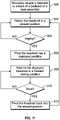
- Figure 11 illustrates a flow chart of a method of forming and/or operating a headrest of a seat assembly, according to an embodiment of the present disclosure.
- the method begins at 300, at which the headrest 110 is moveably coupled to the seat assembly 100.
- the headrest 110 is moveably coupled to the back 112 of the backrest 108 of the seat assembly 100.
- the headrest 110 is retained in the stowed position.
- an individual decides whether to deploy the headrest 110. If the individual does not wish to deploy the headrest 110, the method returns to 302.
- the headrest is pivoted into the deployed position at 306. The individual may then rest on the deployed headrest 110 in a forward resting position.
- the individual decides whether or not to stow the headrest 110. If not, the method may return to 308.
- the headrest 110 is pivoted backed into the stowed position at 312. The method then returns to 302.
- a method of forming a seat assembly includes moveably coupling the headrest to the seat assembly.
- the moveably coupling allows the headrest to be moved between a stowed position in which the headrest is retained within a portion of the backrest and a deployed position in which the headrest is configured to support a passenger in a forward resting position.
- the method may include retaining the headrest in the stowed position within an envelope of the backrest.
- embodiments of the present disclosure provide a seat assembly onboard a vehicle that allows a passenger to comfortably rest in a forward position. Further, embodiments of the present disclosure provide a seat assembly having a comfortable and clean deployable headrest.
- a structure, limitation, or element that is "configured to” perform a task or operation is particularly structurally formed, constructed, or adapted in a manner corresponding to the task or operation.
- an object that is merely capable of being modified to perform the task or operation is not “configured to” perform the task or operation as used herein.
Landscapes
- Engineering & Computer Science (AREA)
- Aviation & Aerospace Engineering (AREA)
- Seats For Vehicles (AREA)
- Chair Legs, Seat Parts, And Backrests (AREA)
Description
- Embodiments of the present disclosure generally relate to interior cabins within vehicles, such as commercial aircraft, and, more particularly, to seat assemblies within interior cabins of vehicles.
- Commercial aircraft typically include an interior cabin that may be divided into numerous sections. A cockpit is generally separated from a passenger cabin, which may include a first class section, a business class section, and a coach section. The passenger cabin may also include one or more work areas for flight personnel, such as galleys, which may include food and beverage storage structures. One or more aisles pass through the passenger cabin and connect each of the passenger sections to one or more paths and/or one or more doors of the aircraft.
- Passenger seats are positioned within the interior cabin. During a flight, particularly a long haul flight, a passenger seated within a seat may decide to rest. A rear portion of a head of a passenger may be supported on a front of a backrest.
- However, the passenger may prefer to rest in a different position. The passenger may prefer to rest in a forward position, such that the head of the passenger abuts into a rear surface of a backrest of a seat in front of the passenger. As another example, the passenger may support the head over a deployed tray table.
- As can be appreciated, however, such positions may not always be ergonomically comfortable, particularly over the entire course of a long haul flight. Moreover, certain passengers may be reluctant to contact a rear of a seat and/or a tray table, due to a lack of comfort and/or perceived levels of cleanliness (or lack thereof).
-
US6,619,733 , in accordance with its abstract, states a passenger headrest that is platform deployable and stowable from a passenger seat. The platform operates as a rear headrest and is pivoted to a forward position to serve as a forward leaning face-headrest. The headrest includes a headrest platform that is attached to an adjustable post made of tubular construction and having a plurality of holes. The adjustable post is concentrically dimensioned to be slidably received by a tubular bar. The tubular bar has a set of holes and is pivotably attached to the passenger seat. A first connector secures the adjustable post and tubular bar to each other. The headrest is pivotable through a range of motion adjusted by a passenger, wherein the passenger selects an inclination angle. The inclination angle used by the passenger is established via a second connector that secures the tubular bar to the seat. -
US2012/181821 according to its abstract states a method and a device for a multi-adjustable body-rest structure suitable for use in a sitting position, including sitting positions in a multi-row seating arrangement such as those encountered on board of airplanes, busses, ferries, and trains, among other similar arrangements. The multi-adjustable body-rest structure is generally configured to be used for rest or sleep while leaning forward from the user seat onto the back of the seat in front of the user seat. The multi-adjustable body-rest structure is further configured to be folded into the back of the seat in front of the user seat when not in use. The multi-adjustable body-rest structure is further configured to be adjusted to a position that comfortably accommodates the head, chest, and arms of users with different body sizes. -
US2017096224 according to its abstract states an airplane seat sleeping device for providing a forwardly inclining head support that is attached or attachable to an adjacently proceeding vehicle seat, which has a seatback. The device includes a seatback attachment mechanism configured to be attachable to the seatback of the adjacently proceeding vehicle seat; a pillow support member; an intermediate member connecting the seatback attachment mechanism to the pillow support member; and a pillow support/receiving holding mechanism. - A need exists for a seat assembly onboard a vehicle that allows a passenger to comfortably rest in a forward resting position. Further, a need exists for a seat assembly having a comfortable and clean deployable headrest.
- With those needs in mind, certain embodiments of the present disclosure provide a seat assembly that includes a seat cushion, a backrest, and a headrest moveably coupled to a back of the backrest. The headrest is configured to be moved between a stowed position in which the headrest is retained within a portion of the backrest and a deployed position in which the headrest is configured to support a passenger in a forward resting position. The seat assembly is defined in claim 1.
- The headrest in the stowed position may be retained within an envelope of the backrest. As an example, the headrest in the stowed position may be flush mounted with the back of the backrest. In at least one embodiment, the headrest in the stowed position is retained within a reciprocal retaining chamber formed in the back of the backrest.
- The seat assembly may also include a moveable latch that securely retains the headrest in the stowed position.
- An electronic device may be secured within the back of the backrest. The headrest in the stowed position may extend around one or more portions of an electronic device.
- The headrest may include a padded insert. The padded insert may be removably secured to a retaining bracket. An antimacassar may be removably secured to the padded insert. In at least one embodiment, the padded insert is configured to be radially shifted relative to a head support beam of the headrest.
- Certain embodiments of the present disclosure provide a method of forming a headrest of a seat assembly, the method is as defined in claim 11.
- Certain embodiments of the present disclosure provide a vehicle that includes an interior cabin, and a seat assembly within the interior cabin, as described herein.
-
-
Figure 1 illustrates a schematic block diagram of a seat assembly within an interior cabin of a vehicle, according to an embodiment of the present disclosure. -
Figure 2 illustrates a front perspective view of an aircraft, according to an embodiment of the present disclosure. -
Figure 3 illustrates a side view of a seat assembly, according to an embodiment of the present disclosure. -
Figure 4 illustrates a perspective rear view of a seat assembly, according to an embodiment of the present disclosure. -
Figure 5 illustrates a rear view of a backrest of a seat assembly, according to an embodiment of the present disclosure. -
Figure 6 illustrates a perspective rear view of a seat assembly having a headrest in a stowed position and a tray table in a deployed position, according to an embodiment of the present disclosure. -
Figure 7 illustrates a perspective rear view of a seat assembly having a headrest in a deployed position and a tray table in a deployed position, according to an embodiment of the present disclosure. -
Figure 8 illustrates a perspective rear view of a backrest of a seat assembly having a headrest in a deployed position, according to an embodiment of the present disclosure. -
Figure 9 illustrates lateral view of a backrest of a seat assembly having a headrest in a deployed position, according to an embodiment of the present disclosure. -
Figure 10 illustrates a perspective rear view of a seat assembly having a headrest in a deployed position and a tray table in a deployed position, according to an embodiment of the present disclosure. -
Figure 11 illustrates a flow chart of a method of forming and/or operating a headrest of a seat assembly, according to an embodiment of the present disclosure. - The foregoing summary, as well as the following detailed description of certain embodiments will be better understood when read in conjunction with the appended drawings. As used herein, an element or step recited in the singular and preceded by the word "a" or "an" should be understood as not necessarily excluding the plural of the elements or steps. Further, references to "one embodiment" are not intended to be interpreted as excluding the existence of additional embodiments that also incorporate the recited features. Moreover, unless explicitly stated to the contrary, embodiments "comprising" or "having" an element or a plurality of elements having a particular property may include additional elements not having that property.
- Certain embodiments of the present disclosure provide a seat assembly, such as may be used within an interior cabin of a vehicle, which includes a deployable headrest. The headrest is moveably secured to a back of a backrest of the seat assembly. The headrest is configured to be moved between a stowed position and a deployed position. In the deployed position, the headrest is configured to comfortably support a passenger in a forward resting position.
- In at least one embodiment, the headrest fits within an existing seat envelope. For example, in the stowed position, the headrest may be flush-mounted with the backrest. The headrest is compact and light, and allows passengers to lean forward in a comfortable resting position.
- The headrest is deployable from the seat assembly in front of a passenger seated in another seat assembly, thereby allowing for a forward resting position. The headrest in the stowed position may be housed within an envelope of the backrest.
- Certain embodiments of the present disclosure provide a seat assembly that includes a backrest having an upper portion and a lower portion. The upper portion includes electronic device and the lower portion includes a tray table. The upper portion includes a deployable headrest that is rearwardly deployable such that a passenger in an adjacent row is able to utilize the deployable headrest. The headrest may be rotatably attached to the upper portion. The headrest may be semi-circumferentially located relative to the electronic device in a stowed position. The headrest is ergonomically adjustable when in a deployed position. In at least one embodiment, the electronic device is an in-flight entertainment (IFE) system.
- The headrest may include a padded portion and an antimacassar. The antimacassar is removable and/or replaceable.
- Certain embodiments of the present disclosure provide a method of manufacturing a seat including providing a seat with a backrest having an upper portion and a lower portion, and pivotally coupling a moveable headrest to the upper portion.
-
Figure 1 illustrates a schematic block diagram of aseat assembly 100 within aninterior cabin 102 of avehicle 104, according to an embodiment of the present disclosure. Thevehicle 104 may be a commercial aircraft, for example. - The
seat assembly 100 includes aseat cushion 106 and abackrest 108. Aheadrest 110 is moveably coupled to a rear or back 112 of thebackrest 108. - The
headrest 110 is moveably coupled to anupper portion 114 of the back 112 of thebackrest 108. - The
headrest 110 is configured to move in the directions of arc A between a deployed position and a stowed position relative to thebackrest 108. Theheadrest 110 is pivotally coupled to thebackrest 108. In the deployed position, theheadrest 110 rearwardly extends from the back 112 of thebackrest 108. In the deployed position, theheadrest 110 is configured to support a head of a passenger in a forward resting position. The passenger is seated in an adjacent seat assembly behind theseat assembly 100. Thus, the passenger may move theheadrest 110 into the deployed position and rest in the forward resting position with theheadrest 110 supporting the face of the passenger. - In the stowed position, the
headrest 110 is retained within the back 112 of thebackrest 108. For example, the passenger may pivot theheadrest 110 into a retaining chamber of thebackrest 108. In the stowed position, theheadrest 110 may not protrude outwardly past the back 112 of thebackrest 108. Instead, theheadrest 110 in the stowed position may be flush-mounted with the back 112 of thebackrest 108. As such, theheadrest 110 in the stowed position is not susceptible to catching or snagging articles within theinterior cabin 102. -
Figure 2 illustrates a front perspective view of a vehicle, such as anaircraft 104, according to an embodiment of the present disclosure. Theaircraft 104 includes apropulsion system 116 that may include twoturbofan engines 118, for example. Optionally, thepropulsion system 116 may includemore engines 118 than shown. Theengines 118 are carried bywings 120 of theaircraft 104. In other embodiments, theengines 118 may be carried by afuselage 122 and/or anempennage 124. Theempennage 124 may also supporthorizontal stabilizers 126 and avertical stabilizer 128. - The
fuselage 122 of theaircraft 104 defines an interior cabin, which may include a cockpit, one or more work sections (for example, galleys, personnel carry-on baggage areas, and the like), one or more passenger sections (for example, first class, business class, and coach sections), and an aft section. Alternatively, instead of an aircraft, embodiments of the present disclosure may be used with various other vehicles, such as automobiles, buses, locomotives and train cars, seacraft, spacecraft, and the like. -
Figure 3 illustrates a side view of aseat assembly 100, according to an embodiment of the present disclosure. Theseat assembly 100 may be configured to be secured within a cabin of a vehicle, such as a commercial aircraft. - The
seat assembly 100 includes abase 130, which may includelegs 132 that may be secured totracks 134 within a cabin of a vehicle. Thelegs 132 may include fittings, fasteners, or the like that are configured to securely connect thelegs 132 to thetracks 134. Thebase 130 supports aseat cushion 106 and abackrest 108. Arm rests 136 may be pivotally secured to thebackrest 108. - As described herein, the headrest 110 (shown in
Figure 1 ) is moveably secured to a back 112 of thebackrest 108, such as through lateral arms that are pivotally secured to thebackrest 108. Additionally, a tray table may also be pivotally secured to the back 112 of thebackrest 108. -
Figure 4 illustrates a perspective rear view of theseat assembly 100, according to an embodiment of the present disclosure.Figure 5 illustrates a rear view of thebackrest 108 of theseat assembly 100. Referring toFigures 4 and5 , theheadrest 110 is shown in a stowed position. Theheadrest 110 may be flush-mounted with thebackrest 108 in the stowed position. In particular, in the stowed position, theheadrest 110 may be contained within anenvelope 150 of thebackrest 108 defined by aheight 152, awidth 154, and athickness 156 of thebackrest 108. In the stowed position, no portion of theheadrest 110 may protrude outwardly past theheight 152, thewidth 154, or thethickness 156 of thebackrest 108. Alternatively, at least a portion of theheadrest 110 in the stowed position may outwardly extend past at least a portion of theenvelope 150 of thebackrest 108. - The
headrest 110 includes ahead support beam 160 that spans between opposed lateral pivot beams 162. Thehead support beam 160 extends betweenupper ends 164 of the lateral pivot beams 162. As shown, thehead support beam 160 may be generally perpendicular to the lateral pivot beams 162. - In the stowed position, the
headrest 110 is retained within areciprocal retaining chamber 166 formed in the back 112 of thebackrest 108. Lower ends 168 of the lateral pivot beams 162 are pivotally coupled to reciprocal structures within the back 112 of thebackrest 108. For example, the lower ends 168 may include pivot pins that are pivotally retained within reciprocal bearings and/or openings within the back 112 of thebackrest 108, or vice versa. - A
moveable latch 170 securely retains theheadrest 110 in the stowed position. Thelatch 170 may be pivoted into a release position, in which thelatch 170 disengages from thehead support beam 160 to allow theheadrest 110 to be downwardly pivoted into a deployed position. - As shown, the
headrest 110 is moveably coupled to anupper portion 172 of the back 112 of thebackrest 108. Theheadrest 110 in the stowed position may extend around one or more portions of anelectronic device 174 secured within the back 112 of thebackrest 108. For example, thehead support beam 160 is positioned over theelectronic device 174, while the lateral pivot beams 162 are positioned to sides of theelectronic device 174. In at least one embodiment, theelectronic device 174 may be a monitor, such as a monitor of an in-flight entertainment (IFE)system 175. - A tray table 180 is moveably coupled to a
lower portion 176 of the back 112 of thebackrest 108. The tray table 180 may be positioned underneath theelectronic device 174. As shown inFigures 4 and5 , the tray table is in a stowed position. - Alternatively, the
seat assembly 100 may not include theelectronic device 174. In at least one other embodiment, the tray table 180 may extend to theupper portion 172 of thebackrest 108. In this embodiment, thelatch 170 may be used to securely latch theheadrest 110 and the tray table 180 in stowed positions. - The
headrest 110 is independent of the tray table 180 and theelectronic device 174. That is, theheadrest 110 is deployable without affecting the use of the tray table 180 and theelectronic device 174, and vice versa. -
Figure 6 illustrates a perspective rear view of theseat assembly 100 having theheadrest 110 in the stowed position and the tray table 180 in a deployed position, according to an embodiment of the present disclosure. Thelatch 170 engages a rear surface of thehead support beam 160 to securely retain theheadrest 110 in the stowed position. The tray table 180 may outwardly unfold into the deployed position.Lateral pivot arms 182 may pivotally couple the tray table 180 to thelower portion 176 of the back 112 of thebackrest 108. In order to move the tray table 180 into a stowed position (as shown inFigures 4 and5 ), the tray table 180 may be folded up and pivoted into areciprocal retaining chamber 184 underneath theelectronic device 174. -
Figure 7 illustrates a perspective rear view of theseat assembly 100 having theheadrest 110 in a deployed position and the tray table 180 in a deployed position, according to an embodiment of the present disclosure. In order to move theheadrest 110 into the deployed position, thelatch 170 is pivoted into a position such that it no longer engages thehead support beam 160. An individual then grasps a portion of theheadrest 110 and pivots theheadrest 110 downwardly into the deployed position, such as by thelateral pivot arms 162 downwardly pivoting in relation to thebackrest 108. As shown, in the deployed position, theheadrest 110 rearwardly extends from the back 112 of thebackrest 108. - The
headrest 110 may be held in a desired position. For example, theheadrest 110 and/or the backrest may include one or more of a clutched or ratcheted locking mechanism, spring-biased pins, removable pins or fasteners, clamps, and/or the like that are configured to securely lock theheadrest 110 into a desired deployed position. -
Figure 8 illustrates a perspective rear view of thebackrest 108 of theseat assembly 100 having theheadrest 110 in a deployed position, according to an embodiment of the present disclosure. As shown, theheadrest 110 pivots around theelectronic device 174. - In at least one embodiment, the
head support beam 160 includes a paddedinsert 200. The paddedinsert 200 may be formed of an open cell foam, and is configured to provide a comfortable, padded surface on which an individual may rest a portion of a face in a forward resting position. The paddedinsert 200 may be retained within a retainingbracket 202. The paddedinsert 200 may be removably coupled to the retainingbracket 202. In this manner, the paddedinsert 200 may be a disposable unit that is configured to be replaced after one or more uses. In at least one other embodiment, the paddedinsert 200 may be permanently fixed to the retainingbracket 202. As another example, thehead support beam 160 may be formed of a padded material, such an open cell foam. - An
antimacassar 204 may be secured over the paddedinsert 200. Theantimacassar 204 may be draped over an outer surface of the paddedinsert 200. In at least one other embodiment, theantimacassar 204 may be removably secured to the paddedinsert 200, such as through Velcro or other such fastening agents. Theantimacassar 204 may be disposable and configured to be removed and replaced after one or more uses. As such, a clean andsterile antimacassar 204 may be used by each passenger. Alternatively, theheadrest 110 may not include theantimacassar 204. -
Figure 9 illustrates lateral view of thebackrest 108 of theseat assembly 100 having theheadrest 110 in a deployed position, according to an embodiment of the present disclosure. Theheadrest 110 is pivoted from the stowed position (as shown inFigures 4 and5 ) into the deployed position. Theheadrest 110 may be positioned in a desired deployed position based on a pivot position of thelateral pivot arms 162 in relation to thebackrest 108. The range of pivotal motion may extend from an upright position (in which theheadrest 110 is stowed in the backrest 108), to a horizontal position that is ninety degrees from the upright position. Optionally, the range of pivotal motion may be greater or lesser than ninety degrees. - Additionally, the padded
insert 200 may be radially shifted relative to thehead support beam 160 in the directions of arc B. For example, the paddedinsert 200 may be upwardly shifted to a position B', or downwardly shifted to a position B". As such, theheadrest 110 may be adjusted in relation to two degrees of freedom, namely with respect to thepivot arms 162 pivoting in relation to thebackrest 108 in the directions of arc A, and with respect to the paddedinsert 200 shifting in relation to thehead support beam 160 in the directions of arc B. Alternatively, the paddedinsert 200 may not be configured to be shifted in relation to thehead support beam 160. - The
headrest 110 and the paddedinsert 200 are adjustable, as described, regardless of the position of theseat assembly 100. For example, thebackrest 108 may be adjusted to different reclining positions, while theheadrest 110 and the paddedinsert 200 are adjustable as described at the various reclining positions. Deployment of theheadrest 110 does not limit adjustability of thebackrest 108, or vice versa. -
Figure 10 illustrates a perspective rear view of aseat assembly 100 having aheadrest 110 in a deployed position and a tray table 180 in a deployed position, according to an embodiment of the present disclosure. In this embodiment, theheadrest 110 may be configured to pivot about an upper interface between thehead support beam 160 and thebackrest 108. Stabilizingbeams 262 connected to thehead support beam 160 swing outwardly, and may be supported on a rear surface of theelectronic device 174, which has been downwardly folded about a pivot axle coupled to theheadrest 110. Theelectronic device 174 may be configured to pivot about a lower interface that is below the upper interface. In the downwardly position, theelectronic device 174 may be positioned over a deployed tray table 180. In the stowed position, theheadrest 110 may be tucked behind the upwardly positionedelectronic device 174 - A
space 263 may extend between the stabilizingbeams 262, which are supported over the rear of the downwardly foldedelectronic device 174. An individual may position a face within thespace 263 between the stabilizing beams 262. Optionally, theseat assembly 100 may not include theelectronic device 174. Instead, theheadrest 110 may be configured to be supported on the deployed tray table 180. -
Figure 11 illustrates a flow chart of a method of forming and/or operating a headrest of a seat assembly, according to an embodiment of the present disclosure. Referring toFigures 1-11 , the method begins at 300, at which theheadrest 110 is moveably coupled to theseat assembly 100. For example, theheadrest 110 is moveably coupled to the back 112 of thebackrest 108 of theseat assembly 100. At 302, theheadrest 110 is retained in the stowed position. - At 304, an individual decides whether to deploy the
headrest 110. If the individual does not wish to deploy theheadrest 110, the method returns to 302. - If, however, the individual does wish to deploy the
headrest 110, the headrest is pivoted into the deployed position at 306. The individual may then rest on the deployedheadrest 110 in a forward resting position. - At 310, the individual decides whether or not to stow the
headrest 110. If not, the method may return to 308. - If, however, the individual wishes to stow the headrest, the
headrest 110 is pivoted backed into the stowed position at 312. The method then returns to 302. - In at least one embodiment, a method of forming a seat assembly includes moveably coupling the headrest to the seat assembly. The moveably coupling allows the headrest to be moved between a stowed position in which the headrest is retained within a portion of the backrest and a deployed position in which the headrest is configured to support a passenger in a forward resting position. The method may include retaining the headrest in the stowed position within an envelope of the backrest.
- As described herein, embodiments of the present disclosure provide a seat assembly onboard a vehicle that allows a passenger to comfortably rest in a forward position. Further, embodiments of the present disclosure provide a seat assembly having a comfortable and clean deployable headrest.
- As used herein, a structure, limitation, or element that is "configured to" perform a task or operation is particularly structurally formed, constructed, or adapted in a manner corresponding to the task or operation. For purposes of clarity and the avoidance of doubt, an object that is merely capable of being modified to perform the task or operation is not "configured to" perform the task or operation as used herein.
- It is to be understood that the above description is intended to be illustrative, and not restrictive. For example, the above-described embodiments (and/or aspects thereof) may be used in combination with each other. While the dimensions and types of materials described herein are intended to define the parameters of the various embodiments of the disclosure, the embodiments are by no means limiting and are exemplary embodiments. Many other embodiments will be apparent to those of skill in the art upon reviewing the above description. In the appended claims, the terms "including" and "in which" are used as the plain-English equivalents of the respective terms "comprising" and "wherein." Moreover, the terms "first," "second," and "third," etc. are used merely as labels, and are not intended to impose numerical requirements on their objects.
- This written description uses examples to disclose the various embodiments of the disclosure, including the best mode, and also to enable any person skilled in the art to practice the various embodiments of the disclosure, including making and using any devices or systems and performing any incorporated methods. The patentable scope of the various embodiments of the disclosure is defined by the claims.
Claims (15)
- A seat assembly (100) comprising:a seat cushion (106);a backrest (108);a headrest (110) with a head support beam (160) and lateral pivot beams (162);wherein the headrest (110) is moveably secured to an upper portion of a back (112) of the backrest through the lateral pivot beams (162);wherein the headrest (110) is configured to be moved between a stowed position in which the headrest (110) is retained within a portion of the backrest (108) and a deployed position in which the headrest (110) is configured to support a passenger in a forward resting position, wherein the head support beam (160) spans between the opposed lateral pivot beams (162);wherein the head support beam (160) extends between upper ends of the lateral pivot beams (162), and wherein lower ends of the lateral pivot beams (162) are pivotally coupled to the back (112) of the backrest (108); anda tray table (180) moveably coupled to a lower portion of the back (112) of the backrest (108),wherein the tray table is positioned below the headrest (110).
- The seat assembly (100) according to claim 1, wherein the headrest (110) in the stowed position is retained within an envelope of the backrest (108).
- The seat assembly (100) according to claim 1 or claim 2, wherein the headrest (110) in the stowed position is flush mounted with the back (112) of the backrest (108).
- The seat assembly (100) according to any one of claims 1-3, wherein the headrest (110) in the stowed position is retained within a reciprocal retaining chamber (184) formed in the back (112) of the backrest (108).
- The seat assembly (100) according to any one of claims 1-4, further comprising a moveable latch (170) that securely retains the headrest (110) in the stowed position.
- The seat assembly (100) according to any one of claims 1-5, further comprising an electronic device (174) secured within the back (112) of the backrest (108) optionally, wherein the headrest (110) in the stowed position extends around one or more portions of the electronic device (174).
- The seat assembly (100) according to any one of claims 1-6, wherein the headrest (110) comprises a padded insert (200).
- The seat assembly (100) according to claim 7, wherein the padded insert (200) is removably secured to a retaining bracket (202).
- The seat assembly (100) according to claim 7 or 8, further comprising an antimacassar (204) removably secured to the padded insert (200).
- The seat assembly (100) according to claim 1, wherein the head support beam (160) of the headrest is formed of a padded material.
- A method of forming a seat assembly (100), the method comprising:moveably securing a headrest (110) comprising a head support beam (160) and lateral pivot beams (162) to an upper portion of a back (112) of a backrest (108) of the seat assembly (100) through lateral pivot beams (162), wherein the head support beam (160) spans between the opposed lateral pivot beams (162); wherein the head support beam (160) extends between upper ends of the lateral pivot beams (162), and wherein lower ends of the lateral pivot beams (162) are pivotally coupled to the back (112) of the backrest (108), wherein the moveably coupling allows the headrest (110) to be moved between a stowed position in which the headrest (110) is retained within a portion of the backrest (108) and a deployed position in which the headrest (110) is configured to support a passenger in a forward resting position; andmoveably coupling a table tray (180) to a lower portion of the back (112) ot the backrest (108) of the seat assembly, wherein the tray table is positioned below the headrest (110).
- The method according to claim 11, further comprising retaining the headrest (110) in the stowed position within an envelope of the backrest (108).
- The method according to any one of claims 11 or 12, further comprising removably securing an antimacassar to a padded insert of the headrest.
- A vehicle (104) comprising:an interior cabin (102); anda seat assembly (100) according to claim 1 within the interior cabin, (102).
- The vehicle (104) according to claim 14,wherein the headrest (110) in the stowed position is retained within an envelope of the backrest (108),wherein the headrest (110) in the stowed position is flush mounted with the back (112) of the backrest (108), wherein the headrest (110) in the stowed position is retained within a reciprocal retaining chamber (184) formed in the back (112) of the backrest (110),wherein the headrest (110) further comprises a padded insert (200) removably secured to a retaining bracket (202) of the head support beam (160), wherein an antimacassar (204) is removably secured to the padded insert (200); andwherein the seat assembly (100) further comprises:a moveable latch (170) that securely retains the headrest (110) in the stowed position;an electronic device (174) secured within the back (112) of the backrest (108), wherein the headrest (110) in the stowed position extends around one or more portions of an electronic device (174).
Applications Claiming Priority (1)
| Application Number | Priority Date | Filing Date | Title |
|---|---|---|---|
| US15/975,829 US10696410B2 (en) | 2018-05-10 | 2018-05-10 | Seat assembly having a deployable headrest |
Publications (2)
| Publication Number | Publication Date |
|---|---|
| EP3566946A1 EP3566946A1 (en) | 2019-11-13 |
| EP3566946B1 true EP3566946B1 (en) | 2022-07-06 |
Family
ID=66476461
Family Applications (1)
| Application Number | Title | Priority Date | Filing Date |
|---|---|---|---|
| EP19173450.8A Active EP3566946B1 (en) | 2018-05-10 | 2019-05-09 | Seat assembly having a deployable headrest |
Country Status (3)
| Country | Link |
|---|---|
| US (1) | US10696410B2 (en) |
| EP (1) | EP3566946B1 (en) |
| AU (1) | AU2019203269B2 (en) |
Families Citing this family (6)
| Publication number | Priority date | Publication date | Assignee | Title |
|---|---|---|---|---|
| EP3515822B1 (en) * | 2016-09-26 | 2020-10-07 | Safran Seats USA LLC | Amenities panel for passenger seat for holding passenger belongings and devices |
| WO2020039237A1 (en) * | 2018-08-24 | 2020-02-27 | Safran Seats Usa Llc | Secondary personal item support |
| WO2020263262A1 (en) * | 2019-06-27 | 2020-12-30 | Safran Seats Usa Llc | Deployable support surface formed from upper shroud |
| US10914457B1 (en) * | 2020-01-30 | 2021-02-09 | The Boeing Company | Bracket for mounting a cover in a lighting unit |
| US12371166B2 (en) * | 2022-08-08 | 2025-07-29 | B/E Aerospace, Inc. | Deployable sleep support system for seated passengers |
| WO2026068996A1 (en) * | 2024-09-30 | 2026-04-02 | Safran Seats Usa Llc | Deployable comfort support for passenger seat |
Citations (2)
| Publication number | Priority date | Publication date | Assignee | Title |
|---|---|---|---|---|
| US20120181821A1 (en) * | 2011-01-17 | 2012-07-19 | Mohsen Edalati | Multi-adjustable body-rest apparatus |
| US20170096224A1 (en) * | 2015-10-06 | 2017-04-06 | Itamar Marom | Vehicle seat sleeping device |
Family Cites Families (19)
| Publication number | Priority date | Publication date | Assignee | Title |
|---|---|---|---|---|
| DE1939206A1 (en) | 1969-08-01 | 1971-02-18 | Feldmuehle Ag | Closure for flat structures |
| US3888329A (en) * | 1971-07-16 | 1975-06-10 | James Monaghan | Vehicle safety device |
| DE3244728A1 (en) * | 1982-12-03 | 1984-06-07 | Dr.Ing.H.C. F. Porsche Ag, 7000 Stuttgart | SEAT FOR AIRPLANES, VEHICLES OR THE LIKE |
| US4667904A (en) | 1984-09-28 | 1987-05-26 | The Boeing Company | Torso restraint with in flight and ejection activation modes |
| US4637629A (en) | 1985-08-01 | 1987-01-20 | Rockwell International Corporation | Non-encumbering torso restraint system |
| US4784352A (en) | 1986-05-20 | 1988-11-15 | Rockwell International Corporation | Forward posture support seat system |
| US4899961A (en) | 1988-06-28 | 1990-02-13 | The Boeing Company | Inflatable, lateral head restraint |
| US5046687A (en) | 1988-07-22 | 1991-09-10 | The Boeing Company | Adaptive torso restraint system |
| JP2587323B2 (en) * | 1990-12-25 | 1997-03-05 | 小糸工業株式会社 | Seat headrest |
| US6619733B2 (en) | 2001-11-19 | 2003-09-16 | The Boeing Company | Passenger seat headrest platform |
| US6805403B2 (en) * | 2002-12-26 | 2004-10-19 | Pradip Chandrakant Buch | Facilitate sleeping of a person in sitting position by supporting the head and/or body |
| US20110141057A1 (en) | 2009-10-02 | 2011-06-16 | Panasonic Avionics Corporation | System and Method for Interacting with Information Systems |
| WO2011070515A1 (en) | 2009-12-08 | 2011-06-16 | Air New Zealand Limited | A seat |
| US8528978B2 (en) | 2011-11-02 | 2013-09-10 | The Boeing Company | Transport vehicle seat back with integrated upright sleep support system |
| US8985693B2 (en) | 2011-11-02 | 2015-03-24 | The Boeing Company | Transport vehicle upright sleep support system |
| CN102514509A (en) * | 2011-11-21 | 2012-06-27 | 陈健全 | An easy-to-operate travel sleep support |
| US8850642B2 (en) * | 2012-04-18 | 2014-10-07 | Steven W. Rasmussen | Support device and methods |
| US10449882B2 (en) * | 2015-03-26 | 2019-10-22 | Nimrod Lev | Travel sleeping aids |
| US20170066354A1 (en) * | 2015-09-09 | 2017-03-09 | Aviointeriors S.P.A. | Seat for means of transport and cushion that can be coupled to the seat |
-
2018
- 2018-05-10 US US15/975,829 patent/US10696410B2/en active Active
-
2019
- 2019-05-09 EP EP19173450.8A patent/EP3566946B1/en active Active
- 2019-05-09 AU AU2019203269A patent/AU2019203269B2/en active Active
Patent Citations (2)
| Publication number | Priority date | Publication date | Assignee | Title |
|---|---|---|---|---|
| US20120181821A1 (en) * | 2011-01-17 | 2012-07-19 | Mohsen Edalati | Multi-adjustable body-rest apparatus |
| US20170096224A1 (en) * | 2015-10-06 | 2017-04-06 | Itamar Marom | Vehicle seat sleeping device |
Also Published As
| Publication number | Publication date |
|---|---|
| EP3566946A1 (en) | 2019-11-13 |
| AU2019203269B2 (en) | 2024-05-30 |
| AU2019203269A1 (en) | 2019-11-28 |
| US20190344896A1 (en) | 2019-11-14 |
| US10696410B2 (en) | 2020-06-30 |
Similar Documents
| Publication | Publication Date | Title |
|---|---|---|
| EP3566946B1 (en) | Seat assembly having a deployable headrest | |
| EP3572325B1 (en) | Deployable partition systems and methods for seat assemblies | |
| EP3704020B1 (en) | Recliner sofa system for economy class seat | |
| US20160376007A1 (en) | Aircraft Seat with Seating and Reclining Positions | |
| CN100441482C (en) | Aircraft Seats and Seat Structures | |
| US9180970B2 (en) | Double cabin attendant seat | |
| US10773626B2 (en) | Adjustable headrest enabling sideward leaning and seclusion | |
| US20050012375A1 (en) | Seat for aircraft | |
| US20140246886A1 (en) | Aircraft divan convertible to a bunk bed | |
| US11597522B2 (en) | Vertically stowed padded tray table for passenger seat | |
| US11685532B2 (en) | Reclinable passenger seat | |
| WO2011053679A1 (en) | Seat pan drop down link | |
| CN112429242B (en) | Configurable cabin crew seat | |
| EP4197910B1 (en) | Reconfigurable seat assembly | |
| US8845030B2 (en) | Passenger seat device | |
| EP3819216B1 (en) | Seat spreader mounted seat privacy closeout | |
| US12304639B2 (en) | Contiguous passenger seat rows configured to form a bed | |
| WO2006054104A1 (en) | Seatbed | |
| US12280877B2 (en) | Swivel backrest with adjustable headrest | |
| US20260062126A1 (en) | Passenger seating utilizing common pivot point for backrest recline and table deployment | |
| EP4516675A1 (en) | Contiguous passenger seat rows configured to form a bed | |
| BR102018071709B1 (en) | LIGHT VEHICLE PASSENGER SEAT MOUNTS |
Legal Events
| Date | Code | Title | Description |
|---|---|---|---|
| PUAI | Public reference made under article 153(3) epc to a published international application that has entered the european phase |
Free format text: ORIGINAL CODE: 0009012 |
|
| STAA | Information on the status of an ep patent application or granted ep patent |
Free format text: STATUS: REQUEST FOR EXAMINATION WAS MADE |
|
| 17P | Request for examination filed |
Effective date: 20190509 |
|
| AK | Designated contracting states |
Kind code of ref document: A1 Designated state(s): AL AT BE BG CH CY CZ DE DK EE ES FI FR GB GR HR HU IE IS IT LI LT LU LV MC MK MT NL NO PL PT RO RS SE SI SK SM TR |
|
| AX | Request for extension of the european patent |
Extension state: BA ME |
|
| RBV | Designated contracting states (corrected) |
Designated state(s): AL AT BE BG CH CY CZ DE DK EE ES FI FR GB GR HR HU IE IS IT LI LT LU LV MC MK MT NL NO PL PT RO RS SE SI SK SM TR |
|
| STAA | Information on the status of an ep patent application or granted ep patent |
Free format text: STATUS: EXAMINATION IS IN PROGRESS |
|
| 17Q | First examination report despatched |
Effective date: 20200918 |
|
| GRAP | Despatch of communication of intention to grant a patent |
Free format text: ORIGINAL CODE: EPIDOSNIGR1 |
|
| STAA | Information on the status of an ep patent application or granted ep patent |
Free format text: STATUS: GRANT OF PATENT IS INTENDED |
|
| RIC1 | Information provided on ipc code assigned before grant |
Ipc: B60N 3/00 20060101ALN20220124BHEP Ipc: B60N 2/874 20180101ALN20220124BHEP Ipc: B64D 11/06 20060101ALI20220124BHEP Ipc: B64D 11/00 20060101AFI20220124BHEP |
|
| INTG | Intention to grant announced |
Effective date: 20220225 |
|
| GRAS | Grant fee paid |
Free format text: ORIGINAL CODE: EPIDOSNIGR3 |
|
| GRAA | (expected) grant |
Free format text: ORIGINAL CODE: 0009210 |
|
| STAA | Information on the status of an ep patent application or granted ep patent |
Free format text: STATUS: THE PATENT HAS BEEN GRANTED |
|
| AK | Designated contracting states |
Kind code of ref document: B1 Designated state(s): AL AT BE BG CH CY CZ DE DK EE ES FI FR GB GR HR HU IE IS IT LI LT LU LV MC MK MT NL NO PL PT RO RS SE SI SK SM TR |
|
| REG | Reference to a national code |
Ref country code: AT Ref legal event code: REF Ref document number: 1502711 Country of ref document: AT Kind code of ref document: T Effective date: 20220715 Ref country code: CH Ref legal event code: EP |
|
| REG | Reference to a national code |
Ref country code: DE Ref legal event code: R096 Ref document number: 602019016598 Country of ref document: DE |
|
| REG | Reference to a national code |
Ref country code: IE Ref legal event code: FG4D |
|
| REG | Reference to a national code |
Ref country code: LT Ref legal event code: MG9D |
|
| REG | Reference to a national code |
Ref country code: NL Ref legal event code: MP Effective date: 20220706 |
|
| PG25 | Lapsed in a contracting state [announced via postgrant information from national office to epo] |
Ref country code: SE Free format text: LAPSE BECAUSE OF FAILURE TO SUBMIT A TRANSLATION OF THE DESCRIPTION OR TO PAY THE FEE WITHIN THE PRESCRIBED TIME-LIMIT Effective date: 20220706 Ref country code: RS Free format text: LAPSE BECAUSE OF FAILURE TO SUBMIT A TRANSLATION OF THE DESCRIPTION OR TO PAY THE FEE WITHIN THE PRESCRIBED TIME-LIMIT Effective date: 20220706 Ref country code: PT Free format text: LAPSE BECAUSE OF FAILURE TO SUBMIT A TRANSLATION OF THE DESCRIPTION OR TO PAY THE FEE WITHIN THE PRESCRIBED TIME-LIMIT Effective date: 20221107 Ref country code: NO Free format text: LAPSE BECAUSE OF FAILURE TO SUBMIT A TRANSLATION OF THE DESCRIPTION OR TO PAY THE FEE WITHIN THE PRESCRIBED TIME-LIMIT Effective date: 20221006 Ref country code: NL Free format text: LAPSE BECAUSE OF FAILURE TO SUBMIT A TRANSLATION OF THE DESCRIPTION OR TO PAY THE FEE WITHIN THE PRESCRIBED TIME-LIMIT Effective date: 20220706 Ref country code: LV Free format text: LAPSE BECAUSE OF FAILURE TO SUBMIT A TRANSLATION OF THE DESCRIPTION OR TO PAY THE FEE WITHIN THE PRESCRIBED TIME-LIMIT Effective date: 20220706 Ref country code: LT Free format text: LAPSE BECAUSE OF FAILURE TO SUBMIT A TRANSLATION OF THE DESCRIPTION OR TO PAY THE FEE WITHIN THE PRESCRIBED TIME-LIMIT Effective date: 20220706 Ref country code: FI Free format text: LAPSE BECAUSE OF FAILURE TO SUBMIT A TRANSLATION OF THE DESCRIPTION OR TO PAY THE FEE WITHIN THE PRESCRIBED TIME-LIMIT Effective date: 20220706 Ref country code: ES Free format text: LAPSE BECAUSE OF FAILURE TO SUBMIT A TRANSLATION OF THE DESCRIPTION OR TO PAY THE FEE WITHIN THE PRESCRIBED TIME-LIMIT Effective date: 20220706 |
|
| REG | Reference to a national code |
Ref country code: AT Ref legal event code: MK05 Ref document number: 1502711 Country of ref document: AT Kind code of ref document: T Effective date: 20220706 |
|
| PG25 | Lapsed in a contracting state [announced via postgrant information from national office to epo] |
Ref country code: PL Free format text: LAPSE BECAUSE OF FAILURE TO SUBMIT A TRANSLATION OF THE DESCRIPTION OR TO PAY THE FEE WITHIN THE PRESCRIBED TIME-LIMIT Effective date: 20220706 Ref country code: IS Free format text: LAPSE BECAUSE OF FAILURE TO SUBMIT A TRANSLATION OF THE DESCRIPTION OR TO PAY THE FEE WITHIN THE PRESCRIBED TIME-LIMIT Effective date: 20221106 Ref country code: HR Free format text: LAPSE BECAUSE OF FAILURE TO SUBMIT A TRANSLATION OF THE DESCRIPTION OR TO PAY THE FEE WITHIN THE PRESCRIBED TIME-LIMIT Effective date: 20220706 Ref country code: GR Free format text: LAPSE BECAUSE OF FAILURE TO SUBMIT A TRANSLATION OF THE DESCRIPTION OR TO PAY THE FEE WITHIN THE PRESCRIBED TIME-LIMIT Effective date: 20221007 |
|
| RAP4 | Party data changed (patent owner data changed or rights of a patent transferred) |
Owner name: THE BOEING COMPANY |
|
| REG | Reference to a national code |
Ref country code: DE Ref legal event code: R097 Ref document number: 602019016598 Country of ref document: DE |
|
| PG25 | Lapsed in a contracting state [announced via postgrant information from national office to epo] |
Ref country code: SM Free format text: LAPSE BECAUSE OF FAILURE TO SUBMIT A TRANSLATION OF THE DESCRIPTION OR TO PAY THE FEE WITHIN THE PRESCRIBED TIME-LIMIT Effective date: 20220706 Ref country code: RO Free format text: LAPSE BECAUSE OF FAILURE TO SUBMIT A TRANSLATION OF THE DESCRIPTION OR TO PAY THE FEE WITHIN THE PRESCRIBED TIME-LIMIT Effective date: 20220706 Ref country code: DK Free format text: LAPSE BECAUSE OF FAILURE TO SUBMIT A TRANSLATION OF THE DESCRIPTION OR TO PAY THE FEE WITHIN THE PRESCRIBED TIME-LIMIT Effective date: 20220706 Ref country code: CZ Free format text: LAPSE BECAUSE OF FAILURE TO SUBMIT A TRANSLATION OF THE DESCRIPTION OR TO PAY THE FEE WITHIN THE PRESCRIBED TIME-LIMIT Effective date: 20220706 Ref country code: AT Free format text: LAPSE BECAUSE OF FAILURE TO SUBMIT A TRANSLATION OF THE DESCRIPTION OR TO PAY THE FEE WITHIN THE PRESCRIBED TIME-LIMIT Effective date: 20220706 |
|
| PLBE | No opposition filed within time limit |
Free format text: ORIGINAL CODE: 0009261 |
|
| STAA | Information on the status of an ep patent application or granted ep patent |
Free format text: STATUS: NO OPPOSITION FILED WITHIN TIME LIMIT |
|
| PG25 | Lapsed in a contracting state [announced via postgrant information from national office to epo] |
Ref country code: SK Free format text: LAPSE BECAUSE OF FAILURE TO SUBMIT A TRANSLATION OF THE DESCRIPTION OR TO PAY THE FEE WITHIN THE PRESCRIBED TIME-LIMIT Effective date: 20220706 Ref country code: EE Free format text: LAPSE BECAUSE OF FAILURE TO SUBMIT A TRANSLATION OF THE DESCRIPTION OR TO PAY THE FEE WITHIN THE PRESCRIBED TIME-LIMIT Effective date: 20220706 |
|
| 26N | No opposition filed |
Effective date: 20230411 |
|
| P01 | Opt-out of the competence of the unified patent court (upc) registered |
Effective date: 20230516 |
|
| PG25 | Lapsed in a contracting state [announced via postgrant information from national office to epo] |
Ref country code: AL Free format text: LAPSE BECAUSE OF FAILURE TO SUBMIT A TRANSLATION OF THE DESCRIPTION OR TO PAY THE FEE WITHIN THE PRESCRIBED TIME-LIMIT Effective date: 20220706 |
|
| PG25 | Lapsed in a contracting state [announced via postgrant information from national office to epo] |
Ref country code: SI Free format text: LAPSE BECAUSE OF FAILURE TO SUBMIT A TRANSLATION OF THE DESCRIPTION OR TO PAY THE FEE WITHIN THE PRESCRIBED TIME-LIMIT Effective date: 20220706 |
|
| REG | Reference to a national code |
Ref country code: CH Ref legal event code: PL |
|
| PG25 | Lapsed in a contracting state [announced via postgrant information from national office to epo] |
Ref country code: MC Free format text: LAPSE BECAUSE OF FAILURE TO SUBMIT A TRANSLATION OF THE DESCRIPTION OR TO PAY THE FEE WITHIN THE PRESCRIBED TIME-LIMIT Effective date: 20220706 |
|
| REG | Reference to a national code |
Ref country code: BE Ref legal event code: MM Effective date: 20230531 |
|
| PG25 | Lapsed in a contracting state [announced via postgrant information from national office to epo] |
Ref country code: MC Free format text: LAPSE BECAUSE OF FAILURE TO SUBMIT A TRANSLATION OF THE DESCRIPTION OR TO PAY THE FEE WITHIN THE PRESCRIBED TIME-LIMIT Effective date: 20220706 Ref country code: LU Free format text: LAPSE BECAUSE OF NON-PAYMENT OF DUE FEES Effective date: 20230509 Ref country code: LI Free format text: LAPSE BECAUSE OF NON-PAYMENT OF DUE FEES Effective date: 20230531 Ref country code: IT Free format text: LAPSE BECAUSE OF FAILURE TO SUBMIT A TRANSLATION OF THE DESCRIPTION OR TO PAY THE FEE WITHIN THE PRESCRIBED TIME-LIMIT Effective date: 20220706 Ref country code: CH Free format text: LAPSE BECAUSE OF NON-PAYMENT OF DUE FEES Effective date: 20230531 |
|
| REG | Reference to a national code |
Ref country code: IE Ref legal event code: MM4A |
|
| PG25 | Lapsed in a contracting state [announced via postgrant information from national office to epo] |
Ref country code: IE Free format text: LAPSE BECAUSE OF NON-PAYMENT OF DUE FEES Effective date: 20230509 |
|
| PG25 | Lapsed in a contracting state [announced via postgrant information from national office to epo] |
Ref country code: IE Free format text: LAPSE BECAUSE OF NON-PAYMENT OF DUE FEES Effective date: 20230509 |
|
| PG25 | Lapsed in a contracting state [announced via postgrant information from national office to epo] |
Ref country code: BE Free format text: LAPSE BECAUSE OF NON-PAYMENT OF DUE FEES Effective date: 20230531 |
|
| PG25 | Lapsed in a contracting state [announced via postgrant information from national office to epo] |
Ref country code: BG Free format text: LAPSE BECAUSE OF FAILURE TO SUBMIT A TRANSLATION OF THE DESCRIPTION OR TO PAY THE FEE WITHIN THE PRESCRIBED TIME-LIMIT Effective date: 20220706 |
|
| PG25 | Lapsed in a contracting state [announced via postgrant information from national office to epo] |
Ref country code: BG Free format text: LAPSE BECAUSE OF FAILURE TO SUBMIT A TRANSLATION OF THE DESCRIPTION OR TO PAY THE FEE WITHIN THE PRESCRIBED TIME-LIMIT Effective date: 20220706 |
|
| PGFP | Annual fee paid to national office [announced via postgrant information from national office to epo] |
Ref country code: DE Payment date: 20250529 Year of fee payment: 7 |
|
| PGFP | Annual fee paid to national office [announced via postgrant information from national office to epo] |
Ref country code: GB Payment date: 20250527 Year of fee payment: 7 |
|
| PGFP | Annual fee paid to national office [announced via postgrant information from national office to epo] |
Ref country code: FR Payment date: 20250526 Year of fee payment: 7 |
|
| PG25 | Lapsed in a contracting state [announced via postgrant information from national office to epo] |
Ref country code: CY Free format text: LAPSE BECAUSE OF FAILURE TO SUBMIT A TRANSLATION OF THE DESCRIPTION OR TO PAY THE FEE WITHIN THE PRESCRIBED TIME-LIMIT; INVALID AB INITIO Effective date: 20190509 |
|
| PG25 | Lapsed in a contracting state [announced via postgrant information from national office to epo] |
Ref country code: HU Free format text: LAPSE BECAUSE OF FAILURE TO SUBMIT A TRANSLATION OF THE DESCRIPTION OR TO PAY THE FEE WITHIN THE PRESCRIBED TIME-LIMIT; INVALID AB INITIO Effective date: 20190509 |
|
| PG25 | Lapsed in a contracting state [announced via postgrant information from national office to epo] |
Ref country code: TR Free format text: LAPSE BECAUSE OF FAILURE TO SUBMIT A TRANSLATION OF THE DESCRIPTION OR TO PAY THE FEE WITHIN THE PRESCRIBED TIME-LIMIT Effective date: 20220706 |