EP3566882B1 - Bicycle rim and wheel - Google Patents
Bicycle rim and wheel Download PDFInfo
- Publication number
- EP3566882B1 EP3566882B1 EP19173350.0A EP19173350A EP3566882B1 EP 3566882 B1 EP3566882 B1 EP 3566882B1 EP 19173350 A EP19173350 A EP 19173350A EP 3566882 B1 EP3566882 B1 EP 3566882B1
- Authority
- EP
- European Patent Office
- Prior art keywords
- rim
- wall
- thickness
- bicycle wheel
- bicycle
- Prior art date
- Legal status (The legal status is an assumption and is not a legal conclusion. Google has not performed a legal analysis and makes no representation as to the accuracy of the status listed.)
- Active
Links
Images




Classifications
-
- B—PERFORMING OPERATIONS; TRANSPORTING
- B60—VEHICLES IN GENERAL
- B60B—VEHICLE WHEELS; CASTORS; AXLES FOR WHEELS OR CASTORS; INCREASING WHEEL ADHESION
- B60B1/00—Spoked wheels; Spokes thereof
- B60B1/003—Spoked wheels; Spokes thereof specially adapted for bicycles
-
- B—PERFORMING OPERATIONS; TRANSPORTING
- B60—VEHICLES IN GENERAL
- B60B—VEHICLE WHEELS; CASTORS; AXLES FOR WHEELS OR CASTORS; INCREASING WHEEL ADHESION
- B60B21/00—Rims
- B60B21/02—Rims characterised by transverse section
-
- B—PERFORMING OPERATIONS; TRANSPORTING
- B60—VEHICLES IN GENERAL
- B60B—VEHICLE WHEELS; CASTORS; AXLES FOR WHEELS OR CASTORS; INCREASING WHEEL ADHESION
- B60B21/00—Rims
- B60B21/06—Rims characterised by means for attaching spokes, i.e. spoke seats
- B60B21/062—Rims characterised by means for attaching spokes, i.e. spoke seats for bicycles
-
- B—PERFORMING OPERATIONS; TRANSPORTING
- B60—VEHICLES IN GENERAL
- B60B—VEHICLE WHEELS; CASTORS; AXLES FOR WHEELS OR CASTORS; INCREASING WHEEL ADHESION
- B60B21/00—Rims
- B60B21/10—Rims characterised by the form of tyre-seat or flange, e.g. corrugated
-
- B—PERFORMING OPERATIONS; TRANSPORTING
- B60—VEHICLES IN GENERAL
- B60B—VEHICLE WHEELS; CASTORS; AXLES FOR WHEELS OR CASTORS; INCREASING WHEEL ADHESION
- B60B5/00—Wheels, spokes, disc bodies, rims, hubs, wholly or predominantly made of non-metallic material
- B60B5/02—Wheels, spokes, disc bodies, rims, hubs, wholly or predominantly made of non-metallic material made of synthetic material
-
- B—PERFORMING OPERATIONS; TRANSPORTING
- B60—VEHICLES IN GENERAL
- B60B—VEHICLE WHEELS; CASTORS; AXLES FOR WHEELS OR CASTORS; INCREASING WHEEL ADHESION
- B60B2360/00—Materials; Physical forms thereof
- B60B2360/30—Synthetic materials
- B60B2360/34—Reinforced plastics
- B60B2360/341—Reinforced plastics with fibres
-
- B—PERFORMING OPERATIONS; TRANSPORTING
- B60—VEHICLES IN GENERAL
- B60B—VEHICLE WHEELS; CASTORS; AXLES FOR WHEELS OR CASTORS; INCREASING WHEEL ADHESION
- B60B2360/00—Materials; Physical forms thereof
- B60B2360/30—Synthetic materials
- B60B2360/34—Reinforced plastics
- B60B2360/341—Reinforced plastics with fibres
- B60B2360/3416—Carbone fibres
-
- B—PERFORMING OPERATIONS; TRANSPORTING
- B60—VEHICLES IN GENERAL
- B60B—VEHICLE WHEELS; CASTORS; AXLES FOR WHEELS OR CASTORS; INCREASING WHEEL ADHESION
- B60B2360/00—Materials; Physical forms thereof
- B60B2360/30—Synthetic materials
- B60B2360/34—Reinforced plastics
- B60B2360/341—Reinforced plastics with fibres
- B60B2360/3418—Aramid fibres
-
- B—PERFORMING OPERATIONS; TRANSPORTING
- B60—VEHICLES IN GENERAL
- B60B—VEHICLE WHEELS; CASTORS; AXLES FOR WHEELS OR CASTORS; INCREASING WHEEL ADHESION
- B60B2360/00—Materials; Physical forms thereof
- B60B2360/30—Synthetic materials
- B60B2360/36—Composite materials
-
- B—PERFORMING OPERATIONS; TRANSPORTING
- B60—VEHICLES IN GENERAL
- B60B—VEHICLE WHEELS; CASTORS; AXLES FOR WHEELS OR CASTORS; INCREASING WHEEL ADHESION
- B60B2900/00—Purpose of invention
- B60B2900/30—Increase in
- B60B2900/311—Rigidity or stiffness
-
- B—PERFORMING OPERATIONS; TRANSPORTING
- B60—VEHICLES IN GENERAL
- B60B—VEHICLE WHEELS; CASTORS; AXLES FOR WHEELS OR CASTORS; INCREASING WHEEL ADHESION
- B60B2900/00—Purpose of invention
- B60B2900/30—Increase in
- B60B2900/313—Resiliency
-
- B—PERFORMING OPERATIONS; TRANSPORTING
- B60—VEHICLES IN GENERAL
- B60B—VEHICLE WHEELS; CASTORS; AXLES FOR WHEELS OR CASTORS; INCREASING WHEEL ADHESION
- B60B2900/00—Purpose of invention
- B60B2900/50—Improvement of
- B60B2900/551—Handling of obstacles or difficult terrains
-
- B—PERFORMING OPERATIONS; TRANSPORTING
- B60—VEHICLES IN GENERAL
- B60B—VEHICLE WHEELS; CASTORS; AXLES FOR WHEELS OR CASTORS; INCREASING WHEEL ADHESION
- B60B2900/00—Purpose of invention
- B60B2900/70—Adaptation for
- B60B2900/711—High loads, e.g. by reinforcements
Definitions
- This invention generally relates to bicycle wheels including rims, and specifically relates to a bicycle rim and wheel including composite materials formed into a wall shape with spoke attachment features and tire attachment features formed therein.
- Bicycle rims for bicycle wheels have been traditionally formed of metal materials, such as aluminum and/or steel based materials. Bicycle rims have also been formed of composite materials, which may be constructed to provide weight benefits of a lighter rim for riders.
- bicycle rims have been formed of fiber reinforced plastics or resins, as well as other composite constructions.
- Composite materials, particularly fiber reinforced plastics or resins have different material properties than traditional metal materials.
- composite material rims are often formed of a hollow, or box, construction resulting in a strong and stiff rim construction.
- a bicycle wheel comprising a rim.
- the bicycle rim includes a single wall formed into the bicycle rim, the wall formed of composite material having a spoke attachment portion and a tire attachment portion formed therein, wherein the composite material comprises at least two different fibers used as reinforcement material forming layers of a thickness of the rim.
- a bicycle wheel comprising a bicycle rim.
- the bicycle rim includes a wall formed into the bicycle rim, the wall formed of composite material having a spoke attachment portion and a tire attachment portion formed therein, the composite material formed of layers providing a thickness of the rim, wherein the composite material includes a layer of the interior of the thickness of the rim that is formed of a different material than both layers of the thickness adjacent the interior layer.
- the composite material may include a carbon fiber. The carbon fiber may be disposed in the adjacent layers.
- the wall is formed absent metallic materials
- a bicycle wheel in an embodiment, includes a rim formed from composite materials, the rim formed as a single wall having a spoke attachment portion and a tire attachment portion, wherein the composite material comprises at least two different fibers used as a reinforcement material forming layers of the thickness of the rim.
- the bicycle wheel according to the invention includes a central hub for rotational attachment to a bicycle frame.
- the bicycle wheel according to the invention also includes a plurality of spokes extending from the tire attachment portion of the rim and attached to the hub.
- a bicycle rim for a bicycle wheel is formed of a single wall of composite material shaped to include both a tire attachment portion and a spoke attachment portion.
- the wall of composite material may be formed as a single-wall construction including minimal to no designed strengthening hollow spaces internally.
- the single-wall construction may be formed of composite strengthening materials, such as fibers or fabrics formed of fibers or other materials. In some applications the strengthening materials may be positioned as layers through a thickness of the single-wall construction. Various types of carbon fibers are used as strengthening materials. Other materials and material fibers may also be used.
- the composite strengthening material may be impregnated with a matrix material, such as a plastic or resin, and solidified through a curing or other process to form a rim structure. In an embodiment, multiple strengthening or reinforcement materials and/or matrix materials may be used to provide specific strength values or other characteristics to the rim construction.
- the rim may be formed having an asymmetric cross sectional profile.
- the center of a spoke attachment recess may not be aligned with a center of an overall width of the rim.
- This asymmetry may be provided to address an asymmetric spoke pattern applied to the rim, resulting in different spoke tension angles, and other considerations.
- one side of a rim may extend wider from the center of the spoke attachment recess than the other side of the rim.
- This configuration may be used to address a dished wheel spoke pattern existent on wheels having wheel hubs configured to include multiple sprockets for a rear drive of a bicycle drivetrain. Dished wheel spoke patterns may also be used on front wheels to compensate for a disk of a braking system attached to the front wheel hub.
- the asymmetric rim configuration includes other geometrical, structural, and construction considerations, as are described herein. For example, a first side of a rim may have a different stiffness than a second side of the rim.
- a single-wall rim of composite construction can provide an increase in strength over hollow composite construction rims.
- single-wall rims may be formed to be stiff enough to maintain stability in normal riding conditions, compliant enough to deform due to an impact loading event of an external structure in aggressive riding environments, and resilient enough to return to an original structure after the impact loading situation or event.
- the single-wall forms a consistent shape throughout the entirety of the circumference of the rim.
- the laminate and/or plies from which the rim is made are altered by changing the composite layers.
- the layers are changed such that an asymmetric width rim has differing laminates and/or plies between a long axial width side of a rim and a short axial width side of the rim.
- Each laminate and/or ply may have a particular set of properties, which may be distinct from other laminates and/or plies in the rim.
- the properties of the two sides of the rim are altered so that once the rim is built into a wheel system, the radial and lateral stiffness of the two rim sides are closer to being equal, despite geometric dissimilarities between the sides. Rims constructed with these techniques may have beneficial characteristics.
- FIG. 1 generally illustrates a bicycle 10 of an off-road or mountain-type configuration including a drive arrangement 18.
- the bicycle 10 includes a frame 12 and front and rear wheels 110, 115 rotatably attached to the frame 12.
- a front brake 20 is provided for braking the front wheel 14 and a rear brake 22 is provided for braking the rear wheel 16.
- Each of the front and rear wheels 110, 115 includes a tire 13 attached to a rim 100, where the tire 13 is configured to engage the riding surface 50.
- a handlebar assembly 24 is provided for steering the front wheel 14.
- the direction of arrow "A" indicates a front and/or forward orientation of the bicycle 10. As such, a forward direction of movement of the bicycle 10 corresponds to the direction A.
- the bicycle 10 may have a road-type configuration. Potential differences between bicycles of various configurations include those between mountain and road-type bicycles.
- FIG. 1 depicts the handlebar assembly 24 in a flat-type configuration, whereas a road-type example may have a drop-type configuration of the handlebar assembly 24.
- a road-type configuration may also include various other features, such as aerodynamic features.
- FIG. 1 depicts features often found on off-road or mountain-type bicycles.
- the front wheel 110 is attached to the frame 12 through a front suspension 26.
- the front suspension 26 may be of a suspension fork configuration as shown.
- the rear wheel 115 may be attached to the frame 12 through a rear suspension 28.
- the front and/or rear suspension 26, 28 may include a combination of springs, dampers, and/or linkages to achieve desired control of the front and rear wheel 110, 115.
- the bicycle 10 also includes a seating component, or saddle 32.
- the adjustable seating component 30 may include a saddle 32 attached to a seat post upper 36 through a seat post head 34.
- the seat post upper 36 is configured to move relative to a seat post lower 38, which is fixed to a seat tube 39 of the frame 12.
- the chain 44 is configured for a multi-gear external drive arrangement and may be moved between individual sprockets of the rear cassette 42 using a gear changer, such as a derailleur 48.
- the gear changer 48 may be operated using any technique.
- the gear change may be electrically operated, mechanically operated, hydraulically operated, or any combination thereof, or operated using other techniques.
- Other drive arrangements may also be used.
- single gearing or multiple gearing internal front or wheel based hub drive arrangements may also be used.
- the front and/or rear wheel 110, 115 of the bicycle 10 include a tire 118 or tire assembly, attached to a radially outer tire engaging portion of the rim 100.
- a plurality of spokes 116 are attached directly to the rim 100 at a radially inner spoke engaging portion of the rim 100.
- the spokes 116 extend from the rim 100 and attach to a central hub 320 or 322.
- the front wheel 110 may have a front wheel hub 120 that is different from a rear wheel hub 322 of the rear wheel 115.
- the spokes 116 are maintained under tension between the rim 100 and the hub 320 or 322 to provide the wheel 110 or 115 an operational rigidity for use on the bicycle 10.
- the hub 320 or 322 is configured for rotational attachment to the bicycle frame 12 about axes of rotation X1, X2 of the rims 100 and wheels 110, 115.
- the rim 100 of the wheel 110 or 115 is formed as an advanced composite structure having a single-wall forming both tire attachment portions and rim attachment portions of the rim 100.
- the single-wall composite structure provides a sufficient strength for aggressive riding in rough terrains. This strength is provided at least in part due to a compliant nature of the single-wall structure which is configured to be rigid enough for control and drive of the bicycle, but compliant so as to moderately deform due to impact loading imparted by the terrain.
- the composite material construction further provides the elasticity to return to the original intended shape of the wheel 110 or 115 after impact loading.
- the rim 100 is configured for attachment to a tire 118 and/or a tire assembly.
- the tire and/or tire assembly includes at least a tire configured for attachment to the rim 100 and tractive interaction with the riding surface 50.
- a tire may also include a resilient structure, such as a pneumatic chamber defined either by the tire's interface with the rim 100, or an inner-tube.
- a tire using a pneumatic chamber may include a control valve 119 configured to control the input and/or output of air into the pneumatic chamber.
- the rim 100 may be configured to facilitate the use of such a control valve 119.
- the rim may include a hole or vacancy configured to allow the passage of the control valve 119 therethrough.
- the tire engaging portion of the rim 100 is configured for attachment to tires using clincher tire attachment configurations for tires including beaded interlock attachments.
- Other configurations of the tire engaging portion may also be provided to allow for the use of other types of tires on the rim 100.
- tubeless tires including beaded interlock attachment types may be used.
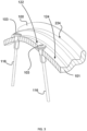
- FIG. 2 is an enlarged and rotated view of the section 2 indicated in FIG. 1 , with the tire 118 and other associated assemblies removed to show the single wall structure of the rim 100 as attached to spokes 116.
- the spokes 116 pass through a wall 101 of the rim 100 in the spoke receiving portion 122 of the rim 100.
- the spokes 116 are secured to the rim 100 using spoke attachment members 103, or nipples.
- the wall 101 also forms a tire attachment portion 224 configured for attachment to a tire construction. As is illustrated in the embodiment shown in FIG. 2 , the tire attachment portion 224 is configured for attachment to clincher tire attachment configurations for tires including beaded interlock attachment.
- the wall 101 is formed of a composite material.
- the wall 101 is formed of a fiber reinforced plastic, epoxy, and/or polymer based material.
- the wall 101 is formed of layers of a reinforcement material, such as carbon fiber, embedded in a matrix material, such as an epoxy and/or polymer based material.
- the rim is formed absent of metal materials.
- multiple reinforcement materials may be used to form the wall 101.
- the multiple reinforcement materials may have different material properties.
- a first reinforcement material used to form the wall may have a finished tenacity value that is lower than a finished tenacity value of a second reinforcement material.
- a finished tenacity value relates to the tenacity of the material after curing or otherwise forming the finished rim and/or wheel.
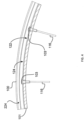
- FIGS. 3 and 4 illustrate section 2 of the rim 100 of FIG. 2 , in a sectional view taken at a plane forming the center of the spoke receiving recess 124. In an embodiment, this plane is formed at the thickest part of the spoke receiving portion 122 of the wall 101.
- spokes 116 are attached to the spoke attachment portion, and load the rim into a tensioned state.
- the wall 101 may be deformed from an un-tensioned state to a tensioned state when spokes are attached and tensioned.
- FIGS. 5A and 5B illustrate sectional views of the rim 100, taken at differing circumferential locations of indicated section 2 of the rim 100 as shown in FIG. 2 .
- FIG. 5A is shown with a cut section through a spoke attachment vacancy 126, provided for spoke 116 or spoke attachment members 103 to pass therethrough and secure to the rim 100.
- FIG. 5B which is taken at a different circumferential location about the rim than the view shown in FIG. 5A so as to illustrate the cross sectional shape of the wall 101 absent the spoke attachment vacancy 126.
- the wall 101 forms a consistent cross sectional shape throughout the circumference of the rim. With no inward protrusions, the wall 101 also provides a consistent inner radial surface 130.
- a consistent cross sectional shape and/or a consistent inner radial surface 130 may have benefits in the manufacturing process, particularly in mold creation and/or removal of a rim from a mold after a curing or other stabilizing process for the rim materials.
- FIG. 6 illustrates the rim 100 attached to a tire 118 at the tire attachment portion 224.
- a control valve 119 is provided to control air in and out of the tire 118. In this view, the spokes and central wheel hub are not shown.
- FIGS. 7A-C illustrate a cross section view of the wall 101 in an un-tensioned state.
- the wall 101 has been formed to include a radially inner spoke attachment portion 122 configured for spoke attachment, and a radially outer tire attachment portion 224 which is configured for attachment to a tire.
- the spoke attachment portion 122 includes a spoke receiving recess 124, providing a spoke attachment surface 127 sunken to a more radially inner position relative to the tire attachment portion 224.
- the spoke receiving recess 124 provides a space for tires including a beaded portion to stage the beaded portion during installation on the rim 100.
- the beaded portion of the tire may be placed in the spoke receiving recess 124.
- air will be forced into an internal vacancy of the tire.
- the beads will be forced outward and up bead escape portions, such as ramps 141A-B, to the tire attachment portion 224.
- the bead retention portion includes the bead bumps 142A-B, bead shelfs 144A-B and bead walls 146A-B.
- the bead shelfs 144A-B constrict the movement of the bead in a radially inner direction, while material properties of the bead restrict further movement of the bead in a radial outer direction.
- the bead walls 146A-B restrict further movement of the bead in an outward axial direction along the rotation axis of the wheel, and the bead bumps 142A-B restrict further movement of the bead in an inner axial direction along the rotation axis of the wheel.
- a top of the bead bumps 142A-B is more radially outer than the bead shelfs 144A-B.
- the bead shelfs 144A-B run parallel to the rotation axis of the wheel, each forming a cylindrical surface about the rotation axis. In an embodiment, the bead walls 146A-B run perpendicular to the rotation axis of the wheel, each forming a disc-like surface about the rotation axis.
- the wall 101 of the rim 100 is formed with an overall width W between external wall portions 148A-B.
- the wall 101 of the rim 100 is formed with an interior width B between bead walls 146A-B.
- the base of the spoke attachment recess 124, or the spoke attachment surface 127 has a midpoint between bead escape transition points 150A-B.
- a plane through the midpoint between bead escape transition points 150A-B and perpendicular to the rotation axis of the rim may be used to define a central plane M of the rim 100, separating the rim 100 into a first side 154A and a second side 154B.
- the wall 101 of the rim 100 is formed such that there is a first distance C from the bead wall 146A of the first side 154A of the rim to the central plane M, and a second distance D from the bead wall 146B of the second side 154B of the rim to the central plane M.
- the first distance C is equal to the second distance D.
- the first distance C is different than the second distance D.
- These axial distances C, D may be referenced as axial widths of the respective bead walls 146A, 146B.
- the first distance C may be shorter than the second distance D.
- a plane formed at half the interior width B and perpendicular to the rotation axis of the rim is offset a distance from the central plane M.
- An asymmetric rim width configuration may be useful in providing clearance or space for a collection of sprockets that may be attached to a rear wheel hub, a disc of a braking system for a front wheel hub, or for other reasons.
- the axial width C of to the bead wall 146A of the first side 154A may be shorter than the axial width D to the bead wall 146B of the second side 154B.
- the rim 100 includes a base section 125 that extends from the spoke receiving surface radially inward towards the axis of rotation of the rim.
- the base section 125 has a maximum thickness Y disposed in the central plane M.
- the thickness Y at the central plane M may be larger than a thickness of any other part of the wall 101 at the base section 125. This increased thickness at the central plane may provide additional strength to resist damage to the rim 100 due to forces imparted on the tire attachment portion 224 of the rim 100.
- a stiffness of a side of a rim may be varied using several factors. For example, varying wall thickness, using different reinforcement materials, and varying ply angles of reinforcement material may be used to specifically tailor a stiffness of the first side 154A and/or the second side 154B.
- a preload tension applied to the rim from spokes of various orientations may be used to adapt the stiffness of the sides.
- Other techniques and combinations of these techniques or others may be used.
- a stiffness of a side may be determined by applying a known load to a portion of the tire attachment portion 224 on a single side of the rim and measuring a deflection towards the rotation axis of the rim.
- an asymmetric width rim may have a first side with a first axial width and a second side with a second axial width, the first and second axial widths being different.
- the rim may be formed in a wheel having spokes connecting the rim with a central hub of the wheel. In an assembled and tensioned state, the first side of the rim and the second side of the rim may have a same radial stiffness.
- Another technique to address asymmetric rim width is to form a rim in a radially asymmetric configuration when in an un-tensioned state.
- the tension may be configured to draw the rim into a more radially symmetric configuration, thus preloading the rim along the rim's elastic deformation curve.
- FIG. 7C illustrates a form of radial asymmetry of the rim 100.
- the rim 100 is formed such that radial distances R1, R2 between an innermost point 162 of the inner radial surface 130 of the rim 100 and the bead shelf 144A of the first side and the bead shelf 144B of the second side are different.
- Tension configurations of the spokes may be used to cause these radial distances R1, R2 to be substantially the same in a pre-loaded state.
- These radial distances R1, R2 may be referenced as radial heights of the respective bead shelfs 144A, 144B.
- the wall 101 of the rim 100 is formed such that the radial height R1 of the bead shelf 144A of the first side 154A is larger than the radial height R2 of the bead shelf 144B of the second side154B.
- the wall 101 of the rim 100 is formed such that the radial height R1 of the bead shelf 144A of the first side 154A is larger than the radial height R2 of the bead shelf 144B of the second side154B and the axial width C of to the bead wall 146A of the first side 154A is shorter than the axial width D to the bead wall 146B of the second side 154B.
- the first side and the second side may also be different in other ways.
- an escape angle of respective sides of the spoke receiving recess 124 may vary.
- a first escape angle ⁇ from the spoke receiving recess 124 of the first side 154A of the rim 100 is different than a second escape angle ⁇ from the spoke receiving recess 124 of the second side 154B of the rim 100.
- the first escape angle ⁇ from the spoke receiving recess 124 of the first side 154A of the rim 100 may be smaller than the second escape angle ⁇ from the spoke receiving recess 124 of the second side 154B of the rim 100.
- the first escape angle ⁇ from the spoke receiving recess 124 of the first side 154A of the rim 100 is between 25 degrees and 30 degrees
- the second escape angle ⁇ from the spoke receiving recess 124 of the second side 154B of the rim 100 is between 55 degrees and 60 degrees.
- the first escape angle ⁇ is approximately half of the second escape angle ⁇ .
- the different escape angles may in the installation of a tire on the rim 100, for example providing a sequenced escape of the tire beads from the spoke receiving recess 124.
- a rim having different escape angles may have different escape ramp lengths.
- a rim is configured such that the first escape ramp 141A from the spoke receiving recess 124 of the first side 154A of the rim is a different length than the second escape ramp 141B from the spoke receiving recess 124 of the second side 154B of the rim.
- the first escape ramp 141A from the spoke receiving recess 124 of the first side 154A of the rim is shorter than the second escape ramp 141B from the spoke receiving recess 124 of the second side rim 154B of the.
- a rim is configured such that the first escape ramp 141A from the spoke receiving recess 124 of the first side 154A of the rim and the second escape ramp 141B from the spoke receiving recess 124 of the second side 154B of the rim are smooth surfaces, with consistent angles from a central plane throughout the length of the ramps 141A, 141B from the spoke receiving surface 127 of the spoke receiving recess, to the bead bumps.
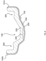
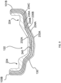
- FIGS. 8 and 9 illustrate a cross section view of embodiments of a rim 100A, 100B that includes at least two ("2") different reinforcement materials.
- the rims 100A, 100B may have a wall 101A, 101B formed with the shape and/or construction as described above with respect to the wall 101 of rim 100 of FIG. 2 , or other shapes and/or constructions.
- the wall 101A includes a thickness formed of multiple parts.
- the wall 101A thickness includes a first, or primary, portion 232, a second, or containment, portion 234, and/or a third, or finishing, portion 233.
- the first portion 232 may be formed of a first, or primary, reinforcement material.
- the second portion 234 may be formed of a second, or containment, reinforcement material.
- the third portion 233 may be formed of a third, or finishing, reinforcement material.
- the second material is different than the first and the third material.
- the first and the third material may be the same or different materials.
- first and the third materials may be the same material and the second material may be different from the first and third materials, and embedded within the first and the third material.
- first material and the third material may be formed of a same basic fiber material, such as carbon fiber, but the first and the third material may be formed into different structures or fabric types.
- the first material and the second material have different material properties.
- the second material may have a higher tenacity value than the first material.
- the first material is a carbon fiber material and the second material is a material having a higher tenacity value ("high-tenacity material") in the finished rim 100A.
- the second material may be an aramid or para-aramid synthetic fiber such as Kevlar ® produced by DUPONT, an olefin or polyolefin fiber such as Innegra S TM produced by INNEGRA TECHNOLOGIES, an ultra-high-molecular-weight polyethylene fiber such as Spectra ® S900 or S1000 produced by HONEYWELL, or combinations thereof.
- the high tenacity material may have a tenacity value of greater than 2000 kN.m/kg, whereas the primary reinforcement material, such as carbon fiber, has a tenacity value lower than 2000 kN.m/kg in the finished rim 100A.
- Having a high tenacity material form a portion of the thickness of the rim may provide for a containment portion of the rim thickness.
- the portion of the thickness having a high tenacity material may operate to arrest or otherwise impede propagation of the breakage in the first material, thus containing the breakage. It is thought that placement of the containment portion 234 radially inner of the first portion 232, as is shown in FIG. 8 , provides an effective configuration for containing breakage propagation of the first material, as forces on the rim 100A typically impact the tire attachment portion, causing breakage propagation in a radially inner direction.
- a containment portion 234 may be disposed radially inward of a middle 240 of a thickness of at least the spoke attachment portion 122 of the rim 100A. In an embodiment, a containment portion 234 may be disposed radially inward of a first portion
- the containment portion 234 is covered by a finishing portion 233.
- the finishing portion 233 may be selected for aesthetic properties, and may not provide significant strength for the rim structure.
- the containment portion 234 may be the most radially inner strengthening portion of the rim 100A.
- the finishing portion 233 may not be used, and the containment portion may be the most radially inner portion of the rim.
- the second portion 234 forms a layer of the thickness of the rim 100A.
- the layer may include one or more plies of fabric formed of fibers of the second material.
- the layer may extend throughout the extent of the wall, as is shown in FIG. 8 , or may extend through less than the extent of the wall.
- the layer of the second portion may extend throughout the spoke retention portion of the rim 100A, but not extend into the tire attachment portion of the rim 100A.
- fibers of the second material forming the second portion 234 may form less than 10% of the total mass of fibers in the rim.
- FIG. 9 illustrates a cross section of an embodiment of the rim 100B that includes multiple containment portions 233A-C.
- the wall 101B includes a thickness formed from a first, or primary, reinforcement portion 232A and multiple second, or containment, reinforcement portions 234A-C, as well as an optional third or finishing portion 233A.
- the wall 101B also includes intermittent portions 235A-B between the containment portions 234A-C.
- the intermittent portions 235A-B are formed of a same material as the first portion 232A.
- the first portion 232A and the intermittent portions 235A-B may be formed of a first material
- the containment portions, 234A-C may be formed of a high tenacity material.
- containment portions may exist both above, at, and/or below a middle 240 of a thickness of at least the spoke attachment portion 122 of the rim 100B.
- three (“3") containment portions 234A-C are shown. More or fewer containment portions may be used.
- the containment portions 234A-C may extend throughout both the spoke attachment portion 122 and the tire attachment portion 224.
- the containment portions 234A-C may form layers throughout the extent of the wall 101B.
- the containment portions may extend through less than an extent of the wall 101B.
- the multiple layers may primarily extend through the spoke attachment portion 122, without extending into the tire attachment portion 224.
- some containment portions may extend throughout the extent of the wall, but other containment portions may exist in only the spoke attachment portion 122 or the tire attachment portion 224.
- a rim has a uniform cross section outline throughout the circumference of the rim.
- holes may be formed in a wall that forms the rim, however, the holes are formed so as to maintain a consistent outline of a cross sectional shape of the rim.
- the holes may be formed for spoke attachment, or other reasons such as pneumatic valve installation.
- a bicycle wheel comprising a bicycle rim.
- the bicycle rim includes a single wall formed into the bicycle rim, the wall formed of composite material having a spoke attachment portion and a tire attachment portion formed therein, wherein the composite material comprises at least two different fibers used as reinforcement material forming layers of a thickness of the rim.
- a first fiber of the composite material comprises a carbon fiber.
- a second fiber of the composite material forms a containment layer in the wall.
- the containment layer is formed as a continuous layer throughout the thickness of the wall.
- the containment layer is formed of fibers having different material properties than the first fibers.
- the containment layer of second fibers has a higher tenacity value than the portions of the thickness of the rim including the first fibers.
- the second fiber is an aramid based fiber, a para-aramid based fiber, an olefin based fiber, a polyolefin based fiber, a polyethylene fiber, or a ultra-high-molecular-weight polyethylene fiber.
- the containment layer including the second fibers has a tenacity value of greater than 2000 kilo-newton-meters per kilogram (kNm/kg), and the portion of the composite material formed of the first fibers has a tenacity value of less than 2000 kNm/kg.
- the containment layer is disposed radially outer of a middle of the thickness of the rim.
- the wall comprises a plurality of containment layers disposed throughout the thickness of the rim.
- the containment layer is disposed radially inner of a middle of the thickness of the rim.
- the containment layer is disposed radially inner of a middle of the thickness of the rim in the spoke attachment portion of the rim.
- the wall is formed such that in an un-tensioned state a first radial height of a first bead shelf of a first side of the rim is different than a second radial height of a second bead shelf of a second side of the rim.
- the wall is formed such that in an un-tensioned state a first side of the rim has a different stiffness than a second side of the rim.
- the wall is formed absent metallic materials.
- a bicycle wheel comprising a bicycle rim.
- the bicycle rim includes a wall formed into the bicycle rim, the wall formed of composite material having a spoke attachment portion and a tire attachment portion formed therein, the composite material formed of layers providing a thickness of the rim, wherein the composite material includes a layer of the interior of the thickness of the rim that is formed of a different material than both layers of the thickness adjacent the interior layer.
- the composite material may include a carbon fiber. The carbon fiber may be disposed in the adjacent layers.
- the wall is formed absent metallic materials.
- a bicycle wheel in an embodiment, includes a rim formed from composite materials, the rim formed as a single wall having a spoke attachment portion and a tire attachment portion, wherein the composite material comprises at least two different fibers used as a reinforcement material forming layers of the thickness of the rim.
- the bicycle wheel also includes a central hub for rotational attachment to a bicycle frame.
- the bicycle wheel also includes a plurality of spokes extending from the tire attachment portion of the rim and attached to the hub.
Landscapes
- Engineering & Computer Science (AREA)
- Mechanical Engineering (AREA)
- Chemical & Material Sciences (AREA)
- Materials Engineering (AREA)
- Tires In General (AREA)
Description
- This invention generally relates to bicycle wheels including rims, and specifically relates to a bicycle rim and wheel including composite materials formed into a wall shape with spoke attachment features and tire attachment features formed therein.
- Bicycle rims for bicycle wheels have been traditionally formed of metal materials, such as aluminum and/or steel based materials. Bicycle rims have also been formed of composite materials, which may be constructed to provide weight benefits of a lighter rim for riders. For example, bicycle rims have been formed of fiber reinforced plastics or resins, as well as other composite constructions. Composite materials, particularly fiber reinforced plastics or resins have different material properties than traditional metal materials. To achieve traditional rim strength levels of rims formed of metal materials, composite material rims are often formed of a hollow, or box, construction resulting in a strong and stiff rim construction.
- Strength values achieved with hollow composite construction rims are acceptable, but the resulting hollow rim structure can be very stiff resulting in damage when used in aggressive environments, such as mountain biking and other off-road bicycling activities. There is a need for a bicycle rim having the weight benefits of composite materials, and a construction increasing a strength and/or resilience of the rim to provide for performance in aggressive bicycling environments. Further prior art is known from
US 6 347 839 B1 andUS 4 741 578 A . - The invention is defined by the independent claims. Specific embodiments are defined by the dependent claims. In an embodiment, a bicycle wheel comprising a rim is provided. The bicycle rim includes a single wall formed into the bicycle rim, the wall formed of composite material having a spoke attachment portion and a tire attachment portion formed therein, wherein the composite material comprises at least two different fibers used as reinforcement material forming layers of a thickness of the rim.
- In an embodiment, a bicycle wheel comprising a bicycle rim is provided. The bicycle rim includes a wall formed into the bicycle rim, the wall formed of composite material having a spoke attachment portion and a tire attachment portion formed therein, the composite material formed of layers providing a thickness of the rim, wherein the composite material includes a layer of the interior of the thickness of the rim that is formed of a different material than both layers of the thickness adjacent the interior layer. The composite material may include a carbon fiber. The carbon fiber may be disposed in the adjacent layers. In an embodiment, the wall is formed absent metallic materials
- In an embodiment, a bicycle wheel is provided. The bicycle wheel includes a rim formed from composite materials, the rim formed as a single wall having a spoke attachment portion and a tire attachment portion, wherein the composite material comprises at least two different fibers used as a reinforcement material forming layers of the thickness of the rim. The bicycle wheel according to the invention includes a central hub for rotational attachment to a bicycle frame. The bicycle wheel according to the invention also includes a plurality of spokes extending from the tire attachment portion of the rim and attached to the hub.
-
-
FIG. 1 is a right side elevational view of a bicycle according to one embodiment; -
FIG. 2 illustrates a section of a bicycle wheel ofFIG. 1 , with a tire assembly removed; -
FIG. 3 illustrates a section side view of the section of the wheel ofFIG. 2 ; -
FIGS. 5A - 5B illustrate different front sectional views of the section of the wheel ofFIG. 2 ; -
FIG. 6 illustrates a side view of the bicycle wheel ofFIG. 1 , with the central hub and spokes removed; -
FIGS. 7A-C illustrate an isolated view of the cross sectional shape of the rim of the bicycle wheel ofFIG. 1 , in an un-tensioned state; -
FIG. 8 illustrates a cross sectional shape of an embodiment of the rim of the bicycle wheel ofFIG. 1 ; and -
FIG. 9 illustrates a cross sectional shape of an embodiment of the rim of the bicycle wheel ofFIG. 1 . - Other aspects and advantages of the embodiments disclosed herein will become apparent upon consideration of the following detailed description, wherein similar or identical structures have similar reference numerals.
- A bicycle rim for a bicycle wheel is formed of a single wall of composite material shaped to include both a tire attachment portion and a spoke attachment portion. The wall of composite material may be formed as a single-wall construction including minimal to no designed strengthening hollow spaces internally. The single-wall construction may be formed of composite strengthening materials, such as fibers or fabrics formed of fibers or other materials. In some applications the strengthening materials may be positioned as layers through a thickness of the single-wall construction. Various types of carbon fibers are used as strengthening materials. Other materials and material fibers may also be used. The composite strengthening material may be impregnated with a matrix material, such as a plastic or resin, and solidified through a curing or other process to form a rim structure. In an embodiment, multiple strengthening or reinforcement materials and/or matrix materials may be used to provide specific strength values or other characteristics to the rim construction.
- The rim may be formed having an asymmetric cross sectional profile. For example, the center of a spoke attachment recess may not be aligned with a center of an overall width of the rim. This asymmetry may be provided to address an asymmetric spoke pattern applied to the rim, resulting in different spoke tension angles, and other considerations. For example, one side of a rim may extend wider from the center of the spoke attachment recess than the other side of the rim. This configuration may be used to address a dished wheel spoke pattern existent on wheels having wheel hubs configured to include multiple sprockets for a rear drive of a bicycle drivetrain. Dished wheel spoke patterns may also be used on front wheels to compensate for a disk of a braking system attached to the front wheel hub. The asymmetric rim configuration includes other geometrical, structural, and construction considerations, as are described herein. For example, a first side of a rim may have a different stiffness than a second side of the rim.
- A single-wall rim of composite construction can provide an increase in strength over hollow composite construction rims. For example, single-wall rims may be formed to be stiff enough to maintain stability in normal riding conditions, compliant enough to deform due to an impact loading event of an external structure in aggressive riding environments, and resilient enough to return to an original structure after the impact loading situation or event. In an embodiment, the single-wall forms a consistent shape throughout the entirety of the circumference of the rim.
- In an embodiment, the laminate and/or plies from which the rim is made are altered by changing the composite layers. The layers are changed such that an asymmetric width rim has differing laminates and/or plies between a long axial width side of a rim and a short axial width side of the rim. Each laminate and/or ply may have a particular set of properties, which may be distinct from other laminates and/or plies in the rim. The properties of the two sides of the rim are altered so that once the rim is built into a wheel system, the radial and lateral stiffness of the two rim sides are closer to being equal, despite geometric dissimilarities between the sides. Rims constructed with these techniques may have beneficial characteristics. For example, cornering left and right becomes similar, giving the rider more control over the bicycle. Also, during wheel impacts, the impact load is shared more equally through both sides of the rim, resulting in a more durable rim. In addition, gains from rim constructions resulting in higher durability allow for the manufacturing of a lighter rim with the same strength as a rim with uneven properties between the long and short sides.
- Embodiments of the invention will herein be described with reference to various figures. It will be understood that the figures and descriptions set out herein are provided for illustration only and do not limit the invention to only disclosed embodiments. For example, the terms "first" and "second," "front" and "rear," or "left" and "right" are used in the detailed description for the sake of clarity and not as terms of limitation. Moreover, the terms refer to bicycle mechanisms conventionally mounted to a bicycle and with the bicycle oriented and used in a standard fashion unless otherwise indicated.
-
FIG. 1 generally illustrates abicycle 10 of an off-road or mountain-type configuration including adrive arrangement 18. Thebicycle 10 includes a frame 12 and front andrear wheels front brake 20 is provided for braking the front wheel 14 and arear brake 22 is provided for braking the rear wheel 16. Each of the front andrear wheels rim 100, where the tire 13 is configured to engage the ridingsurface 50. Ahandlebar assembly 24 is provided for steering the front wheel 14. The direction of arrow "A" indicates a front and/or forward orientation of thebicycle 10. As such, a forward direction of movement of thebicycle 10 corresponds to the direction A. - Other configurations of the
bicycle 10 are contemplated. For example, thebicycle 10 may have a road-type configuration. Potential differences between bicycles of various configurations include those between mountain and road-type bicycles. For example,FIG. 1 depicts thehandlebar assembly 24 in a flat-type configuration, whereas a road-type example may have a drop-type configuration of thehandlebar assembly 24. A road-type configuration may also include various other features, such as aerodynamic features. -
FIG. 1 depicts features often found on off-road or mountain-type bicycles. For example, thefront wheel 110 is attached to the frame 12 through afront suspension 26. Thefront suspension 26 may be of a suspension fork configuration as shown. Therear wheel 115 may be attached to the frame 12 through arear suspension 28. The front and/orrear suspension rear wheel bicycle 10 also includes a seating component, orsaddle 32. The adjustable seating component 30 may include asaddle 32 attached to a seat post upper 36 through a seat post head 34. The seat post upper 36 is configured to move relative to a seat post lower 38, which is fixed to a seat tube 39 of the frame 12. - In the embodiment illustrated in
FIG. 1 thechain 44 is configured for a multi-gear external drive arrangement and may be moved between individual sprockets of therear cassette 42 using a gear changer, such as aderailleur 48. Thegear changer 48 may be operated using any technique. For example, the gear change may be electrically operated, mechanically operated, hydraulically operated, or any combination thereof, or operated using other techniques. Other drive arrangements may also be used. For example, single gearing or multiple gearing internal front or wheel based hub drive arrangements may also be used. - As can be seen in
FIG. 1 , the front and/orrear wheel bicycle 10 include atire 118 or tire assembly, attached to a radially outer tire engaging portion of therim 100. A plurality ofspokes 116 are attached directly to therim 100 at a radially inner spoke engaging portion of therim 100. Thespokes 116 extend from therim 100 and attach to acentral hub front wheel 110 may have a front wheel hub 120 that is different from arear wheel hub 322 of therear wheel 115. Thespokes 116 are maintained under tension between therim 100 and thehub wheel bicycle 10. Thehub rims 100 andwheels rim 100 of thewheel rim 100. - The single-wall composite structure provides a sufficient strength for aggressive riding in rough terrains. This strength is provided at least in part due to a compliant nature of the single-wall structure which is configured to be rigid enough for control and drive of the bicycle, but compliant so as to moderately deform due to impact loading imparted by the terrain. The composite material construction further provides the elasticity to return to the original intended shape of the
wheel - The
rim 100 is configured for attachment to atire 118 and/or a tire assembly. The tire and/or tire assembly includes at least a tire configured for attachment to therim 100 and tractive interaction with the ridingsurface 50. A tire may also include a resilient structure, such as a pneumatic chamber defined either by the tire's interface with therim 100, or an inner-tube. A tire using a pneumatic chamber may include acontrol valve 119 configured to control the input and/or output of air into the pneumatic chamber. Therim 100 may be configured to facilitate the use of such acontrol valve 119. For example, the rim may include a hole or vacancy configured to allow the passage of thecontrol valve 119 therethrough. As will be described further below, the tire engaging portion of therim 100 is configured for attachment to tires using clincher tire attachment configurations for tires including beaded interlock attachments. Other configurations of the tire engaging portion may also be provided to allow for the use of other types of tires on therim 100. For example, tubeless tires including beaded interlock attachment types may be used. -
FIG. 2 is an enlarged and rotated view of thesection 2 indicated inFIG. 1 , with thetire 118 and other associated assemblies removed to show the single wall structure of therim 100 as attached tospokes 116. Thespokes 116 pass through awall 101 of therim 100 in thespoke receiving portion 122 of therim 100. Thespokes 116 are secured to therim 100 usingspoke attachment members 103, or nipples. - The
wall 101 also forms atire attachment portion 224 configured for attachment to a tire construction. As is illustrated in the embodiment shown inFIG. 2 , thetire attachment portion 224 is configured for attachment to clincher tire attachment configurations for tires including beaded interlock attachment. - The
wall 101 is formed of a composite material. For example, thewall 101 is formed of a fiber reinforced plastic, epoxy, and/or polymer based material. In an embodiment, thewall 101 is formed of layers of a reinforcement material, such as carbon fiber, embedded in a matrix material, such as an epoxy and/or polymer based material. In an embodiment, the rim is formed absent of metal materials. - In an embodiment, multiple reinforcement materials may be used to form the
wall 101. The multiple reinforcement materials may have different material properties. For example, a first reinforcement material used to form the wall may have a finished tenacity value that is lower than a finished tenacity value of a second reinforcement material. A finished tenacity value relates to the tenacity of the material after curing or otherwise forming the finished rim and/or wheel. -
FIGS. 3 and4 illustratesection 2 of therim 100 ofFIG. 2 , in a sectional view taken at a plane forming the center of thespoke receiving recess 124. In an embodiment, this plane is formed at the thickest part of thespoke receiving portion 122 of thewall 101. InFIGS. 3 and4 spokes 116 are attached to the spoke attachment portion, and load the rim into a tensioned state. In an embodiment, thewall 101 may be deformed from an un-tensioned state to a tensioned state when spokes are attached and tensioned. -
FIGS. 5A and 5B illustrate sectional views of therim 100, taken at differing circumferential locations ofindicated section 2 of therim 100 as shown inFIG. 2 .FIG. 5A is shown with a cut section through aspoke attachment vacancy 126, provided forspoke 116 or spokeattachment members 103 to pass therethrough and secure to therim 100. When compared to the cut section shown inFIG. 5B , which is taken at a different circumferential location about the rim than the view shown inFIG. 5A so as to illustrate the cross sectional shape of thewall 101 absent thespoke attachment vacancy 126. As can be seen fromFIGS. 5A and 5B , there are no additional protrusions from an innerradial surface 130 of thewall 101 formed for acceptance of thespoke 116 or spokeattachment members 103. As such, thewall 101 forms a consistent cross sectional shape throughout the circumference of the rim. With no inward protrusions, thewall 101 also provides a consistent innerradial surface 130. A consistent cross sectional shape and/or a consistent innerradial surface 130 may have benefits in the manufacturing process, particularly in mold creation and/or removal of a rim from a mold after a curing or other stabilizing process for the rim materials. -
FIG. 6 illustrates therim 100 attached to atire 118 at thetire attachment portion 224. Acontrol valve 119 is provided to control air in and out of thetire 118. In this view, the spokes and central wheel hub are not shown. -
FIGS. 7A-C illustrate a cross section view of thewall 101 in an un-tensioned state. Thewall 101 has been formed to include a radially inner spokeattachment portion 122 configured for spoke attachment, and a radially outertire attachment portion 224 which is configured for attachment to a tire. Thespoke attachment portion 122 includes aspoke receiving recess 124, providing aspoke attachment surface 127 sunken to a more radially inner position relative to thetire attachment portion 224. - The
spoke receiving recess 124 provides a space for tires including a beaded portion to stage the beaded portion during installation on therim 100. For example, the beaded portion of the tire may be placed in thespoke receiving recess 124. To complete installation air will be forced into an internal vacancy of the tire. As the air enters the vacancy, and the tire expands, the beads will be forced outward and up bead escape portions, such asramps 141A-B, to thetire attachment portion 224. - As the bead of the tire escapes the
spoke receiving recess 124, the bead moves over bead retention features, such as bead bumps 142A-B to the bead retention portion. The bead retention portion includes the bead bumps 142A-B, bead shelfs 144A-B andbead walls 146A-B. - The bead shelfs 144A-B constrict the movement of the bead in a radially inner direction, while material properties of the bead restrict further movement of the bead in a radial outer direction. The
bead walls 146A-B restrict further movement of the bead in an outward axial direction along the rotation axis of the wheel, and the bead bumps 142A-B restrict further movement of the bead in an inner axial direction along the rotation axis of the wheel. A top of the bead bumps 142A-B is more radially outer than the bead shelfs 144A-B. In an embodiment, the bead shelfs 144A-B run parallel to the rotation axis of the wheel, each forming a cylindrical surface about the rotation axis. In an embodiment, thebead walls 146A-B run perpendicular to the rotation axis of the wheel, each forming a disc-like surface about the rotation axis. - The
wall 101 of therim 100 is formed with an overall width W betweenexternal wall portions 148A-B. Thewall 101 of therim 100 is formed with an interior width B betweenbead walls 146A-B. The base of thespoke attachment recess 124, or thespoke attachment surface 127, has a midpoint between beadescape transition points 150A-B. A plane through the midpoint between beadescape transition points 150A-B and perpendicular to the rotation axis of the rim may be used to define a central plane M of therim 100, separating therim 100 into afirst side 154A and asecond side 154B. Thewall 101 of therim 100 is formed such that there is a first distance C from thebead wall 146A of thefirst side 154A of the rim to the central plane M, and a second distance D from thebead wall 146B of thesecond side 154B of the rim to the central plane M. In a symmetric width rim the first distance C is equal to the second distance D. - According to the invention, the first distance C is different than the second distance D. These axial distances C, D may be referenced as axial widths of the
respective bead walls bead wall 146A of thefirst side 154A may be shorter than the axial width D to thebead wall 146B of thesecond side 154B. - The
rim 100 includes abase section 125 that extends from the spoke receiving surface radially inward towards the axis of rotation of the rim. In an embodiment, thebase section 125 has a maximum thickness Y disposed in the central plane M. For example, the thickness Y at the central plane M may be larger than a thickness of any other part of thewall 101 at thebase section 125. This increased thickness at the central plane may provide additional strength to resist damage to therim 100 due to forces imparted on thetire attachment portion 224 of therim 100. - External forces acting on an asymmetric width rim from use in an aggressive environment are translated through the
wall 101 to thespoke attachment portion 122 of therim 100, and ultimately to the spokes that are attached to therim 100. The uneven axial widths of the first and second side of the rim cause different moment arms to act on thespoke attachment portion 122. This can be countered by forming thefirst side 154A and thesecond side 154B of therim 100 with particularly crafted un-tensioned stiffnesses. A stiffness of a side of a rim may be varied using several factors. For example, varying wall thickness, using different reinforcement materials, and varying ply angles of reinforcement material may be used to specifically tailor a stiffness of thefirst side 154A and/or thesecond side 154B. Also, a preload tension applied to the rim from spokes of various orientations may be used to adapt the stiffness of the sides. Other techniques and combinations of these techniques or others may be used. A stiffness of a side may be determined by applying a known load to a portion of thetire attachment portion 224 on a single side of the rim and measuring a deflection towards the rotation axis of the rim. - In an embodiment, an asymmetric width rim may have a first side with a first axial width and a second side with a second axial width, the first and second axial widths being different. The rim may be formed in a wheel having spokes connecting the rim with a central hub of the wheel. In an assembled and tensioned state, the first side of the rim and the second side of the rim may have a same radial stiffness.
- Another technique to address asymmetric rim width is to form a rim in a radially asymmetric configuration when in an un-tensioned state. When tension from spokes is applied, the tension may be configured to draw the rim into a more radially symmetric configuration, thus preloading the rim along the rim's elastic deformation curve.
-
FIG. 7C illustrates a form of radial asymmetry of therim 100. As illustrated inFIG. 7C , therim 100 is formed such that radial distances R1, R2 between aninnermost point 162 of the innerradial surface 130 of therim 100 and thebead shelf 144A of the first side and thebead shelf 144B of the second side are different. Tension configurations of the spokes may be used to cause these radial distances R1, R2 to be substantially the same in a pre-loaded state. These radial distances R1, R2 may be referenced as radial heights of the respective bead shelfs 144A, 144B. - In an embodiment, the
wall 101 of therim 100 is formed such that the radial height R1 of thebead shelf 144A of thefirst side 154A is larger than the radial height R2 of thebead shelf 144B of the second side154B. - In an embodiment, the
wall 101 of therim 100 is formed such that the radial height R1 of thebead shelf 144A of thefirst side 154A is larger than the radial height R2 of thebead shelf 144B of the second side154B and the axial width C of to thebead wall 146A of thefirst side 154A is shorter than the axial width D to thebead wall 146B of thesecond side 154B. - In an asymmetric width rim the first side and the second side may also be different in other ways. For example, an escape angle of respective sides of the
spoke receiving recess 124 may vary. In an embodiment, a first escape angle α from thespoke receiving recess 124 of thefirst side 154A of therim 100 is different than a second escape angle β from thespoke receiving recess 124 of thesecond side 154B of therim 100. For example, when measured from a plane parallel to the central plane M of therim 100, the first escape angle α from thespoke receiving recess 124 of thefirst side 154A of therim 100 may be smaller than the second escape angle β from thespoke receiving recess 124 of thesecond side 154B of therim 100. In an embodiment, the first escape angle α from thespoke receiving recess 124 of thefirst side 154A of therim 100 is between 25 degrees and 30 degrees, and the second escape angle β from thespoke receiving recess 124 of thesecond side 154B of therim 100 is between 55 degrees and 60 degrees. In an embodiment the first escape angle α is approximately half of the second escape angle β. The different escape angles may in the installation of a tire on therim 100, for example providing a sequenced escape of the tire beads from thespoke receiving recess 124. Also, a rim having different escape angles may have different escape ramp lengths. - In an embodiment, a rim is configured such that the
first escape ramp 141A from thespoke receiving recess 124 of thefirst side 154A of the rim is a different length than thesecond escape ramp 141B from thespoke receiving recess 124 of thesecond side 154B of the rim. For example, thefirst escape ramp 141A from thespoke receiving recess 124 of thefirst side 154A of the rim is shorter than thesecond escape ramp 141B from thespoke receiving recess 124 of thesecond side rim 154B of the. - In an embodiment, a rim is configured such that the
first escape ramp 141A from thespoke receiving recess 124 of thefirst side 154A of the rim and thesecond escape ramp 141B from thespoke receiving recess 124 of thesecond side 154B of the rim are smooth surfaces, with consistent angles from a central plane throughout the length of theramps spoke receiving surface 127 of the spoke receiving recess, to the bead bumps. -
FIGS. 8 and9 illustrate a cross section view of embodiments of arim rims wall wall 101 ofrim 100 ofFIG. 2 , or other shapes and/or constructions. - In the embodiment shown in
FIG. 8 , thewall 101A includes a thickness formed of multiple parts. Thewall 101A thickness includes a first, or primary,portion 232, a second, or containment,portion 234, and/or a third, or finishing,portion 233. Thefirst portion 232 may be formed of a first, or primary, reinforcement material. Thesecond portion 234 may be formed of a second, or containment, reinforcement material. Thethird portion 233 may be formed of a third, or finishing, reinforcement material. In an embodiment, the second material is different than the first and the third material. In this embodiment, the first and the third material may be the same or different materials. For example, the first and the third materials may be the same material and the second material may be different from the first and third materials, and embedded within the first and the third material. In an embodiment, the first material and the third material may be formed of a same basic fiber material, such as carbon fiber, but the first and the third material may be formed into different structures or fabric types. - The first material and the second material have different material properties. For example, the second material may have a higher tenacity value than the first material. In an embodiment, the first material is a carbon fiber material and the second material is a material having a higher tenacity value ("high-tenacity material") in the
finished rim 100A. For example, the second material may be an aramid or para-aramid synthetic fiber such as Kevlar® produced by DUPONT, an olefin or polyolefin fiber such as Innegra S™ produced by INNEGRA TECHNOLOGIES, an ultra-high-molecular-weight polyethylene fiber such as Spectra® S900 or S1000 produced by HONEYWELL, or combinations thereof. In an embodiment, the high tenacity material may have a tenacity value of greater than 2000 kN.m/kg, whereas the primary reinforcement material, such as carbon fiber, has a tenacity value lower than 2000 kN.m/kg in thefinished rim 100A. - Having a high tenacity material form a portion of the thickness of the rim may provide for a containment portion of the rim thickness. When fibers of the first material break, the portion of the thickness having a high tenacity material may operate to arrest or otherwise impede propagation of the breakage in the first material, thus containing the breakage. It is thought that placement of the
containment portion 234 radially inner of thefirst portion 232, as is shown inFIG. 8 , provides an effective configuration for containing breakage propagation of the first material, as forces on therim 100A typically impact the tire attachment portion, causing breakage propagation in a radially inner direction. In an embodiment, acontainment portion 234 may be disposed radially inward of a middle 240 of a thickness of at least thespoke attachment portion 122 of therim 100A. In an embodiment, acontainment portion 234 may be disposed radially inward of a first portion - In an embodiment, such as that shown in
FIG. 8 , thecontainment portion 234 is covered by a finishingportion 233. The finishingportion 233 may be selected for aesthetic properties, and may not provide significant strength for the rim structure. Thus, thecontainment portion 234 may be the most radially inner strengthening portion of therim 100A. In another embodiment, the finishingportion 233 may not be used, and the containment portion may be the most radially inner portion of the rim. - In an embodiment, the
second portion 234 forms a layer of the thickness of therim 100A. The layer may include one or more plies of fabric formed of fibers of the second material. The layer may extend throughout the extent of the wall, as is shown inFIG. 8 , or may extend through less than the extent of the wall. For example, the layer of the second portion may extend throughout the spoke retention portion of therim 100A, but not extend into the tire attachment portion of therim 100A. In an embodiment, fibers of the second material forming thesecond portion 234 may form less than 10% of the total mass of fibers in the rim. -
FIG. 9 illustrates a cross section of an embodiment of therim 100B that includesmultiple containment portions 233A-C. The wall 101B includes a thickness formed from a first, or primary,reinforcement portion 232A and multiple second, or containment,reinforcement portions 234A-C, as well as an optional third or finishingportion 233A. Thewall 101B also includesintermittent portions 235A-B between thecontainment portions 234A-C. In an embodiment, theintermittent portions 235A-B are formed of a same material as thefirst portion 232A. For example, thefirst portion 232A and theintermittent portions 235A-B may be formed of a first material, and the containment portions, 234A-C may be formed of a high tenacity material. In an embodiment, containment portions may exist both above, at, and/or below a middle 240 of a thickness of at least thespoke attachment portion 122 of therim 100B. - In the embodiment illustrated in
FIG. 9 , three ("3")containment portions 234A-C are shown. More or fewer containment portions may be used. - As illustrated in the embodiment shown in
FIG. 9 , thecontainment portions 234A-C may extend throughout both thespoke attachment portion 122 and thetire attachment portion 224. For example, thecontainment portions 234A-C may form layers throughout the extent of thewall 101B. In other embodiments, the containment portions may extend through less than an extent of thewall 101B. For example, the multiple layers may primarily extend through thespoke attachment portion 122, without extending into thetire attachment portion 224. In another embodiment having multiple containment portions, some containment portions may extend throughout the extent of the wall, but other containment portions may exist in only thespoke attachment portion 122 or thetire attachment portion 224. - In an embodiment, a rim has a uniform cross section outline throughout the circumference of the rim. In this embodiment, holes may be formed in a wall that forms the rim, however, the holes are formed so as to maintain a consistent outline of a cross sectional shape of the rim. The holes may be formed for spoke attachment, or other reasons such as pneumatic valve installation.
- In an embodiment, a bicycle wheel comprising a bicycle rim is provided. The bicycle rim includes a single wall formed into the bicycle rim, the wall formed of composite material having a spoke attachment portion and a tire attachment portion formed therein, wherein the composite material comprises at least two different fibers used as reinforcement material forming layers of a thickness of the rim.
- In an embodiment, a first fiber of the composite material comprises a carbon fiber.
- In an embodiment, a second fiber of the composite material forms a containment layer in the wall.
- In an embodiment, the containment layer is formed as a continuous layer throughout the thickness of the wall.
- In an embodiment, the containment layer is formed of fibers having different material properties than the first fibers.
- In an embodiment, the containment layer of second fibers has a higher tenacity value than the portions of the thickness of the rim including the first fibers.
- In an embodiment, the second fiber is an aramid based fiber, a para-aramid based fiber, an olefin based fiber, a polyolefin based fiber, a polyethylene fiber, or a ultra-high-molecular-weight polyethylene fiber.
- In an embodiment, the containment layer including the second fibers has a tenacity value of greater than 2000 kilo-newton-meters per kilogram (kNm/kg), and the portion of the composite material formed of the first fibers has a tenacity value of less than 2000 kNm/kg.
- In an embodiment, the containment layer is disposed radially outer of a middle of the thickness of the rim.
- In an embodiment, the wall comprises a plurality of containment layers disposed throughout the thickness of the rim.
- In an embodiment, the containment layer is disposed radially inner of a middle of the thickness of the rim.
- In an embodiment, the containment layer is disposed radially inner of a middle of the thickness of the rim in the spoke attachment portion of the rim.
- According to the invention, the wall is formed such that in an un-tensioned state a first radial height of a first bead shelf of a first side of the rim is different than a second radial height of a second bead shelf of a second side of the rim.
- In an embodiment, the wall is formed such that in an un-tensioned state a first side of the rim has a different stiffness than a second side of the rim.
- In an embodiment, the wall is formed absent metallic materials.
- In an embodiment, a bicycle wheel comprising a bicycle rim is provided. The bicycle rim includes a wall formed into the bicycle rim, the wall formed of composite material having a spoke attachment portion and a tire attachment portion formed therein, the composite material formed of layers providing a thickness of the rim, wherein the composite material includes a layer of the interior of the thickness of the rim that is formed of a different material than both layers of the thickness adjacent the interior layer. The composite material may include a carbon fiber. The carbon fiber may be disposed in the adjacent layers. In an embodiment, the wall is formed absent metallic materials.
- In an embodiment, a bicycle wheel is provided. The bicycle wheel includes a rim formed from composite materials, the rim formed as a single wall having a spoke attachment portion and a tire attachment portion, wherein the composite material comprises at least two different fibers used as a reinforcement material forming layers of the thickness of the rim. The bicycle wheel also includes a central hub for rotational attachment to a bicycle frame. The bicycle wheel also includes a plurality of spokes extending from the tire attachment portion of the rim and attached to the hub.
- The illustrations of the embodiments described herein are intended to provide a general understanding of the structure of the various embodiments. The illustrations are not intended to serve as a complete description of all of the elements and features of apparatus and systems that utilize the structures or methods described herein. The illustrations are merely representational and may not be drawn to scale, unless otherwise indicated. Certain proportions within the illustrations may be exaggerated, while other proportions may be minimized. Accordingly, the disclosure and the figures are to be regarded as illustrative rather than restrictive.
- While this specification contains many specifics, these should not be construed as limitations on the scope of the invention or of what may be claimed, but rather as descriptions of features specific to particular embodiments of the invention.
- In the foregoing Detailed Description, various features may be grouped together or described in a single embodiment for the purpose of streamlining the disclosure. This disclosure is not to be interpreted as reflecting an intention that the embodiments require more features than are expressly recited in each claim. It is intended that the foregoing detailed description be regarded as illustrative rather than limiting.
Claims (13)
- A bicycle wheel (110, 115), comprising:a bicycle rim (100);a central hub (320, 322) for rotational attachment to a bicycle frame (12); anda plurality of spokes (116) extending from a tire attachment portion (224) of the rim (100) and attached to the hub (320, 322),the rim (100), comprising:
a single wall (101) formed into the rim (100), the wall (101) formed of composite material having a spoke attachment portion (103) and the tire attachment portion (224) formed therein, characterized in that the wall (101) is formed such that:in an un-tensioned state, a first radial height (R1) of a first bead shelf (144A) of a first side (154A) of the rim (100) is different than a second radial height (R2) of a second bead shelf (144B) of a second side (154B) of the rim (100);in the un-tensioned state, a first distance (C) of a first bead wall (146A) of the first side (154A) of the rim (100) to a centre plane (B) of the rim (100) is different from a second distance (D) of a second bead wall (146A) of the second side (154A) of the rim (100) to the centre plane (M); andin a tensioned state, when the spokes (116) are attached to the rim (100) and tensioned, tension configurations of the spokes (116) cause the first and second radial height (R1, R2) to be substantially the same. - The bicycle wheel (110, 115) of claim 1, wherein the composite material comprises at least two different fibers used as reinforcement material forming layers of a thickness of the rim.
- The bicycle wheel (110, 115) of claim 1 or 2, wherein a first fiber (232) of the composite material comprises a carbon fiber.
- The bicycle wheel (110, 115) of claim 3, wherein a second fiber (234) of the composite material forms a containment layer in the wall.
- The bicycle wheel (110, 115) of claim 4, wherein the containment layer (234) is formed as a continuous layer throughout the thickness of the wall (101), or wherein the containment layer is formed of fibers having different material properties than the first fibers.
- The bicycle wheel (110, 115) of claim 5, wherein the containment layer of second fibers has a higher tenacity value than the portions of the thickness of the rim (100) including the first fibers.
- The bicycle wheel (110, 115) of claim 6, wherein the second fiber is an aramid based fiber, a para-aramid based fiber, an olefin based fiber, a polyolefin based fiber, a polyethylene fiber, or a ultra-high-molecular-weight polyethylene fiber, or wherein the containment layer (234) including the second fibers has a tenacity value of greater than 2000 kilo-newton-meters per kilogram (kNm/kg), and the portion of the composite material formed of the first fibers has a tenacity value of less than 2000 kNm/kg.
- The bicycle wheel (110, 115) of claim 5, wherein the containment layer (234) is disposed radially outer of a middle of the thickness of the rim (100), wherein optionally the wall (101) comprises a plurality of containment layers (234A, 234B, 234C) disposed throughout the thickness of the rim (100).
- The bicycle wheel (110, 115) of claim 5, wherein the containment layer (234) is disposed radially inner of a middle of the thickness of the rim (100), wherein optionally the containment layer (234) is disposed radially inner of a middle of the thickness of the rim (100) in the spoke attachment portion (103) of the rim.
- The bicycle wheel (110, 115) of one of the preceding claims, wherein the wall (101) is formed such that in an un-tensioned state a first side of the rim (100) has a different stiffness than a second side of the rim (100).
- The bicycle wheel (110, 115) of one of the preceding claims, wherein the wall (101) is formed absent metallic materials.
- The bicycle wheel (110, 115) of one of the preceding claims, wherein:
the composite material is formed of layers providing a thickness of the rim (100), wherein the composite material includes a layer of the interior of the thickness of the rim (100) that is formed of a different material than both layers of the thickness adjacent the interior layer. - The bicycle wheel (110, 115) of claim 12, wherein the composite material comprises a carbon fiber, wherein optionally the carbon fiber is disposed in the adjacent layers.
Applications Claiming Priority (2)
| Application Number | Priority Date | Filing Date | Title |
|---|---|---|---|
| US201862669101P | 2018-05-09 | 2018-05-09 | |
| US16/398,620 US11897282B2 (en) | 2018-05-09 | 2019-04-30 | Bicycle rim and wheel |
Publications (2)
| Publication Number | Publication Date |
|---|---|
| EP3566882A1 EP3566882A1 (en) | 2019-11-13 |
| EP3566882B1 true EP3566882B1 (en) | 2025-05-07 |
Family
ID=66476400
Family Applications (1)
| Application Number | Title | Priority Date | Filing Date |
|---|---|---|---|
| EP19173350.0A Active EP3566882B1 (en) | 2018-05-09 | 2019-05-08 | Bicycle rim and wheel |
Country Status (5)
| Country | Link |
|---|---|
| US (1) | US11897282B2 (en) |
| EP (1) | EP3566882B1 (en) |
| CN (1) | CN110466283B (en) |
| DE (1) | DE102019003260A1 (en) |
| TW (2) | TWI718530B (en) |
Families Citing this family (2)
| Publication number | Priority date | Publication date | Assignee | Title |
|---|---|---|---|---|
| US11701918B1 (en) * | 2019-04-17 | 2023-07-18 | Hed Cycling Products, Inc. | Bicycle rim adapted to reduce spoke fatigue |
| CN110682733A (en) * | 2019-11-15 | 2020-01-14 | 山东贞元汽车车轮有限公司 | Ultra-light vacuum wheel and automobile using same |
Citations (1)
| Publication number | Priority date | Publication date | Assignee | Title |
|---|---|---|---|---|
| EP2098382B1 (en) * | 2008-03-07 | 2011-05-18 | Kunshan Henry Metal Technology Co., Ltd. | Motor bicycle rim and method of making the same |
Family Cites Families (43)
| Publication number | Priority date | Publication date | Assignee | Title |
|---|---|---|---|---|
| US2368254A (en) | 1944-01-07 | 1945-01-30 | Lyon George Albert | Wheel structure |
| US3392772A (en) | 1966-06-06 | 1968-07-16 | Firestone Tire & Rubber Co | Pneumatic tire and a replaceable unit therewith |
| US3947070A (en) | 1974-07-15 | 1976-03-30 | Schwinn Bicycle Company | Bicycle wheel reflector |
| US4164133A (en) | 1975-11-21 | 1979-08-14 | Holland Mechanics B.V. | Apparatus for forming circularly bent articles from a straight metal profiled strip |
| US4030754A (en) | 1976-01-21 | 1977-06-21 | Hercules Incorporated | Composite lightweight wheel rim |
| US4741578A (en) | 1984-08-21 | 1988-05-03 | Viellard Paul Henri | Assembly of composite materials forming a spoke wheel rim |
| DE3722307A1 (en) * | 1987-07-06 | 1989-01-26 | Anatolij Sergeevic Cygankov | WHEEL FOR A BICYCLE |
| US5820709A (en) | 1994-03-11 | 1998-10-13 | National Tire Co., Ltd. | Vehicle tire and rim combination |
| US5540485A (en) | 1994-11-10 | 1996-07-30 | Enders; Mark L. | Composite bicycle wheel |
| US5975645A (en) | 1996-09-09 | 1999-11-02 | Compositech, Inc. | Carbon bodied bicycle rim |
| IT240914Y1 (en) | 1996-09-27 | 2001-04-11 | Vittoria Spa Off | RIM STRUCTURE FOR CYCLE WHEELS IN GENERAL SUITABLE FOR MORE EASY AND STABLE ASSEMBLY OF THE COVER. |
| IT245313Y1 (en) | 1998-06-05 | 2002-03-20 | Aprilia World Service B V | PERFECTED SPOKE WHEEL |
| US6347839B1 (en) | 2000-09-25 | 2002-02-19 | Polymeric Corporation The | Composite rim |
| ITTO20010121A1 (en) | 2001-02-13 | 2002-08-13 | Campagnolo Srl | PROCEDURE FOR THE MANUFACTURE OF A BICYCLE WHEEL RIM, DEVICE FOR THE IMPLEMENTATION OF THE PROCEDURE, AND THE CIRCLE SO OBTAINED |
| US6425641B1 (en) | 2001-02-13 | 2002-07-30 | Jas. D. Easton, Inc. | Spoked cycle wheel |
| FR2836865B1 (en) * | 2002-03-11 | 2004-05-14 | Michelin Soc Tech | WHEEL WITH COMPOSITE RIM MADE BY RTM PROCESS |
| US7334846B2 (en) | 2004-10-06 | 2008-02-26 | Koziatek Stanley F | Bicycle wheel rim |
| US7464994B2 (en) | 2006-03-03 | 2008-12-16 | Shimano Inc. | Bicycle rim reinforced with a continuously extending resin material |
| ITMI20061401A1 (en) | 2006-07-19 | 2008-01-20 | Ruotemilano S R L | DEVICE FOR FIXING A RADIUS TO THE RIM OF A SPOKE WHEEL |
| ITMI20061670A1 (en) | 2006-09-01 | 2008-03-02 | Campagnolo Srl | RIM FOR BICYCLE RAY WHEEL, SUITABLE PROCEDURE FOR ITS MANUFACTURE AND ITS ROLLER WHEEL. |
| TWM317937U (en) | 2007-01-18 | 2007-09-01 | Jr-Shiang Yang | Wheel rim structure of bicycle |
| US20080315676A1 (en) | 2007-03-22 | 2008-12-25 | John Cobb | Wheel rim components, rims, wheels, wheeled apparatus, and methods of making and using such |
| DE202007018487U1 (en) | 2007-04-24 | 2008-10-09 | Dt Swiss Ag | Rim and apparatus for making a rim |
| ATE514567T1 (en) | 2007-07-30 | 2011-07-15 | Kunshan Henry Metal Tech Co | MOTORCYCLE RIM AND METHOD FOR THE PRODUCTION THEREOF |
| IT1391976B1 (en) | 2008-11-18 | 2012-02-02 | Cicli Pinarello S P A | PERFECT WHEEL STRUCTURE |
| US20100301663A1 (en) | 2009-05-26 | 2010-12-02 | Mad Fibers, Llc | Composite fiber bicycle wheels |
| WO2011133557A1 (en) | 2010-04-19 | 2011-10-27 | Simon Smart | Multi-surface rim for enhanced efficiency |
| US8905491B2 (en) | 2010-07-27 | 2014-12-09 | Shimano Inc. | Bicycle rim |
| CN102602240A (en) | 2011-01-24 | 2012-07-25 | 天心工业股份有限公司 | Bicycle rim and manufacturing method thereof |
| US20130043717A1 (en) | 2011-08-18 | 2013-02-21 | Sram, Llc | Bicycle rim with integral impact resistant structure and methods of making |
| JP6304888B2 (en) | 2011-12-06 | 2018-04-04 | ムベア カルボ テック ゲーエムベーハーMubea Carbo Tech Gmbh | Wheel made of fiber reinforced material and corresponding wheel manufacturing method |
| TWM431075U (en) * | 2011-12-29 | 2012-06-11 | Jalco Industry Co Ltd | Wheel rim structure |
| DE102012202048A1 (en) | 2012-02-10 | 2013-08-14 | Bayerische Motoren Werke Aktiengesellschaft | Method for producing a wheel rim made of fiber composite material and wheel rim for a motor vehicle |
| TWM459128U (en) | 2013-03-05 | 2013-08-11 | Jun-Xiong Wang | Assembly-type bicycle rim structure |
| US9550394B2 (en) | 2013-03-27 | 2017-01-24 | Reynolds Cycling, Llc | Bicycle wheels with asymmetric carbon fiber rims |
| CN103302873B (en) | 2013-05-02 | 2015-07-08 | 莹信工业股份有限公司 | Method for manufacturing composite material rim |
| TW201501965A (en) | 2013-07-03 | 2015-01-16 | Wei-Ping Lin | Composite bicycle rim structure with spoke joint seat |
| TW201504077A (en) * | 2013-07-19 | 2015-02-01 | Alex Global Technology Inc | Bicycle wheel structure |
| CN104175791B (en) | 2014-08-14 | 2017-01-18 | 维多利亚工业有限公司 | Fiber-reinforced composite rim with cooling capability |
| US9981500B2 (en) | 2014-12-04 | 2018-05-29 | Enve Composites, Llc | Impact resistant rim |
| TW201700313A (en) | 2015-06-23 | 2017-01-01 | 亞獵士科技股份有限公司 | Rim structure for bike |
| US20170080749A1 (en) * | 2015-09-23 | 2017-03-23 | Raymond Anderson Scruggs | Optimized Rim For Robust Pneumatic Bicycle Wheel Functionality |
| TWM529610U (en) | 2016-02-22 | 2016-10-01 | Ritchey Designs Inc | Improved structure of eccentric rear wheel rim |
-
2019
- 2019-04-30 US US16/398,620 patent/US11897282B2/en active Active
- 2019-05-06 TW TW108115613A patent/TWI718530B/en active
- 2019-05-06 TW TW110100460A patent/TWI836176B/en active
- 2019-05-08 DE DE102019003260.8A patent/DE102019003260A1/en active Pending
- 2019-05-08 EP EP19173350.0A patent/EP3566882B1/en active Active
- 2019-05-09 CN CN201910383772.0A patent/CN110466283B/en active Active
Patent Citations (1)
| Publication number | Priority date | Publication date | Assignee | Title |
|---|---|---|---|---|
| EP2098382B1 (en) * | 2008-03-07 | 2011-05-18 | Kunshan Henry Metal Technology Co., Ltd. | Motor bicycle rim and method of making the same |
Also Published As
| Publication number | Publication date |
|---|---|
| TWI718530B (en) | 2021-02-11 |
| CN110466283A (en) | 2019-11-19 |
| CN110466283B (en) | 2023-08-08 |
| US11897282B2 (en) | 2024-02-13 |
| DE102019003260A1 (en) | 2019-11-14 |
| TW202003279A (en) | 2020-01-16 |
| US20190344615A1 (en) | 2019-11-14 |
| TW202130522A (en) | 2021-08-16 |
| TWI836176B (en) | 2024-03-21 |
| EP3566882A1 (en) | 2019-11-13 |
Similar Documents
| Publication | Publication Date | Title |
|---|---|---|
| US5490719A (en) | Racing wheel | |
| EP0634978B1 (en) | Vehicle wheel | |
| TWI527715B (en) | Composite bicycle wheel | |
| US8002362B2 (en) | Optimal thermal properties in light weight and high performance braking composite clincher or tubular tire bicycle wheel rim | |
| EP3378676B1 (en) | Tire and wheel assembly having a non-pneumatic support structure | |
| EP1225063A2 (en) | Compliant rim and wheel assembly | |
| US20200331291A1 (en) | Bicycle rim with enlarged outer radial edges | |
| KR20180054484A (en) | Non-pneumatic support structure | |
| EP3599107B1 (en) | Wheel for a support structure | |
| EP3566882B1 (en) | Bicycle rim and wheel | |
| US9718305B2 (en) | Bicycle rim | |
| US20190308446A1 (en) | Bicycle composite clincher rim and wheel | |
| US10252570B2 (en) | Bicycle rim | |
| GB2525931A (en) | Disc wheel | |
| EP4008563B1 (en) | Tire/wheel assembly and method for supporting a vehicle | |
| JPWO2018216626A1 (en) | Wheel and vehicle equipped therewith | |
| KR20240041958A (en) | rims for wheels | |
| US8967732B2 (en) | Rim of a fibrous composite material for at least partially muscle-powered bicycles | |
| EP2502754A1 (en) | A wheel rim and a method for its manufacture | |
| US20250222717A1 (en) | Aerodynamically optimized bicycle wheel | |
| JP7385472B2 (en) | Fiber-reinforced resin wheels and vehicles equipped with them |
Legal Events
| Date | Code | Title | Description |
|---|---|---|---|
| PUAI | Public reference made under article 153(3) epc to a published international application that has entered the european phase |
Free format text: ORIGINAL CODE: 0009012 |
|
| STAA | Information on the status of an ep patent application or granted ep patent |
Free format text: STATUS: REQUEST FOR EXAMINATION WAS MADE |
|
| 17P | Request for examination filed |
Effective date: 20190508 |
|
| AK | Designated contracting states |
Kind code of ref document: A1 Designated state(s): AL AT BE BG CH CY CZ DE DK EE ES FI FR GB GR HR HU IE IS IT LI LT LU LV MC MK MT NL NO PL PT RO RS SE SI SK SM TR |
|
| AX | Request for extension of the european patent |
Extension state: BA ME |
|
| STAA | Information on the status of an ep patent application or granted ep patent |
Free format text: STATUS: EXAMINATION IS IN PROGRESS |
|
| 17Q | First examination report despatched |
Effective date: 20220727 |
|
| RIC1 | Information provided on ipc code assigned before grant |
Ipc: B60B 21/06 20060101ALN20231004BHEP Ipc: B60B 1/00 20060101ALN20231004BHEP Ipc: B60B 21/02 20060101ALI20231004BHEP Ipc: B60B 5/02 20060101AFI20231004BHEP |
|
| GRAP | Despatch of communication of intention to grant a patent |
Free format text: ORIGINAL CODE: EPIDOSNIGR1 |
|
| RIC1 | Information provided on ipc code assigned before grant |
Ipc: B60B 21/06 20060101ALN20241023BHEP Ipc: B60B 1/00 20060101ALN20241023BHEP Ipc: B60B 21/02 20060101ALI20241023BHEP Ipc: B60B 5/02 20060101AFI20241023BHEP |
|
| STAA | Information on the status of an ep patent application or granted ep patent |
Free format text: STATUS: GRANT OF PATENT IS INTENDED |
|
| RIC1 | Information provided on ipc code assigned before grant |
Ipc: B60B 21/06 20060101ALN20241108BHEP Ipc: B60B 1/00 20060101ALN20241108BHEP Ipc: B60B 21/02 20060101ALI20241108BHEP Ipc: B60B 5/02 20060101AFI20241108BHEP |
|
| INTG | Intention to grant announced |
Effective date: 20241128 |
|
| GRAS | Grant fee paid |
Free format text: ORIGINAL CODE: EPIDOSNIGR3 |
|
| GRAA | (expected) grant |
Free format text: ORIGINAL CODE: 0009210 |
|
| STAA | Information on the status of an ep patent application or granted ep patent |
Free format text: STATUS: THE PATENT HAS BEEN GRANTED |
|
| AK | Designated contracting states |
Kind code of ref document: B1 Designated state(s): AL AT BE BG CH CY CZ DE DK EE ES FI FR GB GR HR HU IE IS IT LI LT LU LV MC MK MT NL NO PL PT RO RS SE SI SK SM TR |
|
| REG | Reference to a national code |
Ref country code: GB Ref legal event code: FG4D |
|
| REG | Reference to a national code |
Ref country code: CH Ref legal event code: EP |
|
| REG | Reference to a national code |
Ref country code: DE Ref legal event code: R096 Ref document number: 602019069548 Country of ref document: DE |
|
| REG | Reference to a national code |
Ref country code: IE Ref legal event code: FG4D |
|
| REG | Reference to a national code |
Ref country code: NL Ref legal event code: MP Effective date: 20250507 |
|
| PG25 | Lapsed in a contracting state [announced via postgrant information from national office to epo] |
Ref country code: PT Free format text: LAPSE BECAUSE OF FAILURE TO SUBMIT A TRANSLATION OF THE DESCRIPTION OR TO PAY THE FEE WITHIN THE PRESCRIBED TIME-LIMIT Effective date: 20250908 Ref country code: FI Free format text: LAPSE BECAUSE OF FAILURE TO SUBMIT A TRANSLATION OF THE DESCRIPTION OR TO PAY THE FEE WITHIN THE PRESCRIBED TIME-LIMIT Effective date: 20250507 Ref country code: ES Free format text: LAPSE BECAUSE OF FAILURE TO SUBMIT A TRANSLATION OF THE DESCRIPTION OR TO PAY THE FEE WITHIN THE PRESCRIBED TIME-LIMIT Effective date: 20250507 |
|
| PGFP | Annual fee paid to national office [announced via postgrant information from national office to epo] |
Ref country code: DE Payment date: 20250709 Year of fee payment: 7 |
|
| REG | Reference to a national code |
Ref country code: LT Ref legal event code: MG9D |
|
| PG25 | Lapsed in a contracting state [announced via postgrant information from national office to epo] |
Ref country code: GR Free format text: LAPSE BECAUSE OF FAILURE TO SUBMIT A TRANSLATION OF THE DESCRIPTION OR TO PAY THE FEE WITHIN THE PRESCRIBED TIME-LIMIT Effective date: 20250808 Ref country code: NO Free format text: LAPSE BECAUSE OF FAILURE TO SUBMIT A TRANSLATION OF THE DESCRIPTION OR TO PAY THE FEE WITHIN THE PRESCRIBED TIME-LIMIT Effective date: 20250807 |
|
| PG25 | Lapsed in a contracting state [announced via postgrant information from national office to epo] |
Ref country code: PL Free format text: LAPSE BECAUSE OF FAILURE TO SUBMIT A TRANSLATION OF THE DESCRIPTION OR TO PAY THE FEE WITHIN THE PRESCRIBED TIME-LIMIT Effective date: 20250507 Ref country code: NL Free format text: LAPSE BECAUSE OF FAILURE TO SUBMIT A TRANSLATION OF THE DESCRIPTION OR TO PAY THE FEE WITHIN THE PRESCRIBED TIME-LIMIT Effective date: 20250507 |
|
| REG | Reference to a national code |
Ref country code: AT Ref legal event code: MK05 Ref document number: 1792082 Country of ref document: AT Kind code of ref document: T Effective date: 20250507 |
|
| PG25 | Lapsed in a contracting state [announced via postgrant information from national office to epo] |
Ref country code: BG Free format text: LAPSE BECAUSE OF FAILURE TO SUBMIT A TRANSLATION OF THE DESCRIPTION OR TO PAY THE FEE WITHIN THE PRESCRIBED TIME-LIMIT Effective date: 20250507 |
|
| PG25 | Lapsed in a contracting state [announced via postgrant information from national office to epo] |
Ref country code: HR Free format text: LAPSE BECAUSE OF FAILURE TO SUBMIT A TRANSLATION OF THE DESCRIPTION OR TO PAY THE FEE WITHIN THE PRESCRIBED TIME-LIMIT Effective date: 20250507 |
|
| PG25 | Lapsed in a contracting state [announced via postgrant information from national office to epo] |
Ref country code: AT Free format text: LAPSE BECAUSE OF FAILURE TO SUBMIT A TRANSLATION OF THE DESCRIPTION OR TO PAY THE FEE WITHIN THE PRESCRIBED TIME-LIMIT Effective date: 20250507 |
|
| PG25 | Lapsed in a contracting state [announced via postgrant information from national office to epo] |
Ref country code: RS Free format text: LAPSE BECAUSE OF FAILURE TO SUBMIT A TRANSLATION OF THE DESCRIPTION OR TO PAY THE FEE WITHIN THE PRESCRIBED TIME-LIMIT Effective date: 20250807 |
|
| PG25 | Lapsed in a contracting state [announced via postgrant information from national office to epo] |
Ref country code: IS Free format text: LAPSE BECAUSE OF FAILURE TO SUBMIT A TRANSLATION OF THE DESCRIPTION OR TO PAY THE FEE WITHIN THE PRESCRIBED TIME-LIMIT Effective date: 20250907 |
|
| PG25 | Lapsed in a contracting state [announced via postgrant information from national office to epo] |
Ref country code: LV Free format text: LAPSE BECAUSE OF FAILURE TO SUBMIT A TRANSLATION OF THE DESCRIPTION OR TO PAY THE FEE WITHIN THE PRESCRIBED TIME-LIMIT Effective date: 20250507 |
|
| REG | Reference to a national code |
Ref country code: CH Ref legal event code: H13 Free format text: ST27 STATUS EVENT CODE: U-0-0-H10-H13 (AS PROVIDED BY THE NATIONAL OFFICE) Effective date: 20251223 |
|
| PG25 | Lapsed in a contracting state [announced via postgrant information from national office to epo] |
Ref country code: DK Free format text: LAPSE BECAUSE OF FAILURE TO SUBMIT A TRANSLATION OF THE DESCRIPTION OR TO PAY THE FEE WITHIN THE PRESCRIBED TIME-LIMIT Effective date: 20250507 Ref country code: SM Free format text: LAPSE BECAUSE OF FAILURE TO SUBMIT A TRANSLATION OF THE DESCRIPTION OR TO PAY THE FEE WITHIN THE PRESCRIBED TIME-LIMIT Effective date: 20250507 |
|
| PG25 | Lapsed in a contracting state [announced via postgrant information from national office to epo] |
Ref country code: LU Free format text: LAPSE BECAUSE OF NON-PAYMENT OF DUE FEES Effective date: 20250508 |
|
| PG25 | Lapsed in a contracting state [announced via postgrant information from national office to epo] |
Ref country code: CH Free format text: LAPSE BECAUSE OF NON-PAYMENT OF DUE FEES Effective date: 20250531 |
|
| PG25 | Lapsed in a contracting state [announced via postgrant information from national office to epo] |
Ref country code: CZ Free format text: LAPSE BECAUSE OF FAILURE TO SUBMIT A TRANSLATION OF THE DESCRIPTION OR TO PAY THE FEE WITHIN THE PRESCRIBED TIME-LIMIT Effective date: 20250507 |
|
| PG25 | Lapsed in a contracting state [announced via postgrant information from national office to epo] |
Ref country code: EE Free format text: LAPSE BECAUSE OF FAILURE TO SUBMIT A TRANSLATION OF THE DESCRIPTION OR TO PAY THE FEE WITHIN THE PRESCRIBED TIME-LIMIT Effective date: 20250507 |
|
| PG25 | Lapsed in a contracting state [announced via postgrant information from national office to epo] |
Ref country code: SK Free format text: LAPSE BECAUSE OF FAILURE TO SUBMIT A TRANSLATION OF THE DESCRIPTION OR TO PAY THE FEE WITHIN THE PRESCRIBED TIME-LIMIT Effective date: 20250507 Ref country code: RO Free format text: LAPSE BECAUSE OF FAILURE TO SUBMIT A TRANSLATION OF THE DESCRIPTION OR TO PAY THE FEE WITHIN THE PRESCRIBED TIME-LIMIT Effective date: 20250507 |
|
| PG25 | Lapsed in a contracting state [announced via postgrant information from national office to epo] |
Ref country code: IT Free format text: LAPSE BECAUSE OF FAILURE TO SUBMIT A TRANSLATION OF THE DESCRIPTION OR TO PAY THE FEE WITHIN THE PRESCRIBED TIME-LIMIT Effective date: 20250507 |
|
| REG | Reference to a national code |
Ref country code: BE Ref legal event code: MM Effective date: 20250531 |
|
| REG | Reference to a national code |
Ref country code: DE Ref legal event code: R097 Ref document number: 602019069548 Country of ref document: DE |
|
| PG25 | Lapsed in a contracting state [announced via postgrant information from national office to epo] |
Ref country code: MC Free format text: LAPSE BECAUSE OF FAILURE TO SUBMIT A TRANSLATION OF THE DESCRIPTION OR TO PAY THE FEE WITHIN THE PRESCRIBED TIME-LIMIT Effective date: 20250507 |
|
| PLBE | No opposition filed within time limit |
Free format text: ORIGINAL CODE: 0009261 |
|
| STAA | Information on the status of an ep patent application or granted ep patent |
Free format text: STATUS: NO OPPOSITION FILED WITHIN TIME LIMIT |
|
| REG | Reference to a national code |
Ref country code: CH Ref legal event code: L10 Free format text: ST27 STATUS EVENT CODE: U-0-0-L10-L00 (AS PROVIDED BY THE NATIONAL OFFICE) Effective date: 20260318 |
|
| PG25 | Lapsed in a contracting state [announced via postgrant information from national office to epo] |
Ref country code: IE Free format text: LAPSE BECAUSE OF NON-PAYMENT OF DUE FEES Effective date: 20250508 |
|
| 26N | No opposition filed |
Effective date: 20260210 |
|
| PG25 | Lapsed in a contracting state [announced via postgrant information from national office to epo] |
Ref country code: BE Free format text: LAPSE BECAUSE OF NON-PAYMENT OF DUE FEES Effective date: 20250531 |
|
| PG25 | Lapsed in a contracting state [announced via postgrant information from national office to epo] |
Ref country code: FR Free format text: LAPSE BECAUSE OF NON-PAYMENT OF DUE FEES Effective date: 20250707 |