EP3566829A1 - Shaving assembly and hair cutting appliance - Google Patents
Shaving assembly and hair cutting appliance Download PDFInfo
- Publication number
- EP3566829A1 EP3566829A1 EP18171809.9A EP18171809A EP3566829A1 EP 3566829 A1 EP3566829 A1 EP 3566829A1 EP 18171809 A EP18171809 A EP 18171809A EP 3566829 A1 EP3566829 A1 EP 3566829A1
- Authority
- EP
- European Patent Office
- Prior art keywords
- guard
- shaving assembly
- guard foil
- foil
- curved
- Prior art date
- Legal status (The legal status is an assumption and is not a legal conclusion. Google has not performed a legal analysis and makes no representation as to the accuracy of the status listed.)
- Withdrawn
Links
Images


Classifications
-
- B—PERFORMING OPERATIONS; TRANSPORTING
- B26—HAND CUTTING TOOLS; CUTTING; SEVERING
- B26B—HAND-HELD CUTTING TOOLS NOT OTHERWISE PROVIDED FOR
- B26B19/00—Clippers or shavers operating with a plurality of cutting edges, e.g. hair clippers, dry shavers
- B26B19/38—Details of, or accessories for, hair clippers, or dry shavers, e.g. housings, casings, grips, guards
- B26B19/3846—Blades; Cutters
Definitions
- Embodiments of present disclosure generally relate to home appliance, and more specifically, to a shaving assembly and a hair cutting appliance including the shaving assembly.
- Conventional trimmers or clippers for shaving and grooming facial hairs are designed to cut the hairs at a certain distance from the skin. Close shaving trimmers use a modified construction to enable hair cutting at a much closer distance from the skin than conventional trimmers. Normally, close shaving trimmers relies on thinner guard-teeth. Further, for achieving an effective and comfortable trim, complex rounding features and other features may also be needed.
- the first skin-contacting portion of the teeth may be constructed, for example, from a moldable material (such as, plastic) combined with the thin metal guard teeth to enable the close hair cutting.
- a moldable material such as, plastic
- a thin and flat metal sheet with guard teeth or hair-catching cut-outs is stretched over a molded base.
- This type of construction has an advantage in terms of cost, as it can be simply constructed from a flat sheet of thin foil.
- this construction does not address the comfort and safety issue at the sides gliding over the skin.
- the edges of both glide sides are straight and not optimal for shaving comfort or safety, as they are formed from a thin flat sheet by punching or cutting. In this case, uncomfortableness would be caused when the sharp glide slides are applied and glided on the skin.
- embodiments of the present disclosure provide a shaving assembly with a protection element and a hair cutting appliance including the shaving assembly.
- a shaving assembly comprises: a supporting member; a cutting element extending in the first direction; a guard foil stretched and extending in the first direction and surrounding the cutting element, the guard foil including a bent part and a flat contact surface, wherein the bent part extends in the first direction for fixing the guard foil on the supporting member, and the flat contact surface is adapted to be in contact with skin; and a protection element arranged at at least one end of the guard foil and including a curved surface exposed to the skin.
- the protection element and the end of the guard foil are integrally formed.
- the protection element includes a rounded surface transiting from the contact surface of the guard foil to a bottom surface of the guard foil, wherein the rounded surface has a rounding radius larger than or equal to a thickness of the guard foil.
- the protection element includes a curved portion transiting from the guard foil and constructed to be gradually curved in a direction away from the skin, wherein the curved portion includes a first curved surface transiting from the contact surface of the guard foil and a second curved surface transiting from a bottom surface of the guard foil.
- the protection element includes: a first curved portion transiting from the guard foil and constructed to be gradually curved in a direction towards the skin; and a second curved portion transiting from the first curved portion and constructed to be gradually curved in a direction away from the skin, wherein the first curved portion and the second curved portion jointly define the curved surface.
- the protection element is constructed as a bead made of lacquer or resin and having a rounded profile surrounding the end of the guard foil.
- Such protection element formed by for example a simple dipping or edge-painting of the sharp edge can provide an effective and low-cost protection solution. Moreover, a sufficient durability for the shaving lifetime of the shaving assembly can be achieved.
- the protection element is constructed as a sidewall of the supporting member, wherein the sidewall includes the curved surface projecting beyond the contact surface in a second direction that is substantially perpendicular to the first direction. In some embodiments, the sidewall surrounds the end of the guard foil.
- the sidewall may also function as the side cover of the shaving assembly to close the internal space defined by the supporting element and the guard foil during the hair cutting, so that the cut-off hair may be at least temporarily kept within the internal space without going to the ambient.
- the contact surface includes a plurality of guard teeth arranged along the first direction; and the cutting element includes a plurality of moving teeth arranged along the first direction and adapted to move with respect to the plurality of guard teeth along the first direction.
- a hair cutting appliance comprises: a shaving assembly according to the first aspect of the present disclosure; and a driving mechanism configured to cause a movement of the cutting element inside the shaving assembly.
- FIG. 1A illustrates a perspective view of a conventional shaving assembly 100 in an unassembled status.
- the shaving assembly 100 generally includes a supporting member 1, a cutting element 2 extending in a first direction X, and a guard foil 3 also extending in the first direction X.
- FIG. 1B illustrates a perspective view of the shaving assembly 100 in an assembled status.
- the guard foil 3 is stretched and surrounding the cutting element 2 via a bend of a part of the guard foil 3 with respect to an axis along the first direction X.
- the thickness of the guard foil 3 is in a range of 40 to 120 micrometers, for example, 80 micrometers.
- the flat contact surface 31 also includes two glide edges 39 which are oriented substantially perpendicular to the first direction X and exposed to the user's skin with no protection means provided thereon. As discussed above, in view of the fact that the glide edges 39 are formed by punching or cutting from a thin metal foil, these two glide edges 39 are usually sharp and not optimal for shaving comfort or safety.
- the shaving assembly 100 as shown in FIGs. 1A-1B is further equipped with a skin-friendly protection element 4.
- the protection element 4 is arranged at the ends 310 of the guard foil 3 and includes a curved surface 41 exposed to the skin of the user. In this way, a direct contact of sharp edges with the skin of the user can be avoided, thereby improving the shaving comfort and guaranteeing the shaving safety.
- FIGs. 2A-6C Various embodiments of the shaving assembly 100 with the protection element 4 are described below with reference to FIGs. 2A-6C .
- the protection element 4 and the ends 310 of the guard foil 3 can be integrally formed. In other words, the protection element 4 may be considered as a part of the guard foil.
- the protection element 4 may include a rounded surface 32 that is transiting from the contact surface 31 of the guard foil 3 to a bottom surface 33 of the guard foil 3.
- FIG. 2B shows a cross-sectional view of the protection element 4 along the first direction X. As shown, the rounded surface 32 may have a rounding radius R that is larger than or equal to a thickness T of the guard foil 3.
- Such an arced edge with a radius approaching the thickness of the guard foil 3 (may also referred to as "a radiused edge”) can be achieved, for example, by polishing the edges of the contact surface 31.
- the radiused edge does not change the overall flat shape of the contact surface 31 and only locally changes the profile of the edge in the thickness direction, or in other words, the bottom surface 33 of the guard foil 3 is kept substantially flat. Therefore, the overall stiffness of the guard foil 3 can be well maintained. Moreover, no additional element or part, as well as the simple polishing proceeding, make the protection element cost-effective.
- the protection element 4 includes a curved portion 34 transiting from the guard foil 3 and constructed to be gradually curved in a direction away from the skin Y1.
- the curved portion 34 includes a first curved surface 34 1 transiting from the contact surface 31 of the guard foil 3 and a second curved surface 34 2 transiting from a bottom surface 33 of the guard foil 3.
- the protection element 4 may include a first curved portion 35 and a second curved portion 36, and which jointly define the curved surface 41.
- the first curved portion 35 is transiting from the guard foil 3 and constructed to be gradually curved in a direction towards the skin Y2
- the second curved portion 36 is transiting from the first curved portion 35 and constructed to be gradually curved in a direction away from the skin Y1.
- first curved portion 35 and the second curved portion 36 may have a uniform thickness T2 that is substantially equal to a thickness T of the guard foil 3. In some other embodiments, variation in thickness throughout the first curved portion 35 and second curved portion 36 may be allowed
- the protection element 4 is constructed as a sidewall 42 of the supporting member 1.
- the sidewall 42 includes the curved surface 41 projecting beyond the contact surface 31 in a second direction Y that is substantially perpendicular to the first direction X.
- the side wall 42 may be integrally formed with the supporting member 1.
- the side wall 42 may also be a separate component that is detachable from the supporting member 1.
- the sidewall 42 may surround the end 310 of the guard foil 3 to completely protect the end 310 of the guard foil 3 from being exposed to the user's skin.
- the original design of the guard foil 3 is not affected, which eases the fabrication of the guard foil 3.
- such modular components-based shaving assembly 100 allows manufacturers to individually fabricate all necessary components and store them for a future assembly.
- the sidewall 42 may also function as the side cover of the shaving assembly 100 to close the internal space defined by the supporting element 1 and the guard foil 3 during the hair cutting. In this way, the cut-off hair may be at least temporarily kept within the internal space without going to the ambient.
Landscapes
- Life Sciences & Earth Sciences (AREA)
- Forests & Forestry (AREA)
- Engineering & Computer Science (AREA)
- Mechanical Engineering (AREA)
- Dry Shavers And Clippers (AREA)
Abstract
Embodiments of present disclosure relates to a shaving assembly and a hair cutting appliance including the shaving assembly. The shaving assembly comprises: a supporting member; a cutting element extending in the first direction; a guard foil stretched and extending in the first direction and surrounding the cutting element, the guard foil including a bent part and a flat contact surface, wherein the bent part extends in the first direction for fixing the guard foil on the supporting member, and the flat contact surface is adapted to be in contact with skin; and a protection element arranged at at least one end of the guard foil and including a curved surface exposed to the skin.
Description
- Embodiments of present disclosure generally relate to home appliance, and more specifically, to a shaving assembly and a hair cutting appliance including the shaving assembly.
- Conventional trimmers or clippers for shaving and grooming facial hairs are designed to cut the hairs at a certain distance from the skin. Close shaving trimmers use a modified construction to enable hair cutting at a much closer distance from the skin than conventional trimmers. Normally, close shaving trimmers relies on thinner guard-teeth. Further, for achieving an effective and comfortable trim, complex rounding features and other features may also be needed.
- In a construction, the first skin-contacting portion of the teeth may be constructed, for example, from a moldable material (such as, plastic) combined with the thin metal guard teeth to enable the close hair cutting.
- In an alternative construction as disclosed in
CN106346519A , a thin and flat metal sheet with guard teeth or hair-catching cut-outs is stretched over a molded base. This type of construction has an advantage in terms of cost, as it can be simply constructed from a flat sheet of thin foil. However, this construction does not address the comfort and safety issue at the sides gliding over the skin. The edges of both glide sides are straight and not optimal for shaving comfort or safety, as they are formed from a thin flat sheet by punching or cutting. In this case, uncomfortableness would be caused when the sharp glide slides are applied and glided on the skin. - In order to solve the discomfort and even safety issues caused by the sharp glide sides, embodiments of the present disclosure provide a shaving assembly with a protection element and a hair cutting appliance including the shaving assembly.
- In first aspect, a shaving assembly is provided. The shaving assembly comprises: a supporting member; a cutting element extending in the first direction; a guard foil stretched and extending in the first direction and surrounding the cutting element, the guard foil including a bent part and a flat contact surface, wherein the bent part extends in the first direction for fixing the guard foil on the supporting member, and the flat contact surface is adapted to be in contact with skin; and a protection element arranged at at least one end of the guard foil and including a curved surface exposed to the skin.
- According to embodiments of the present disclosure, the protection element can effectively avoid a direct contact of the user's skin with the non-proceeded sharp edges, thereby enabling a skin-friendly contact with the user's skin.
- In some embodiments, the protection element and the end of the guard foil are integrally formed. In some embodiments, the protection element includes a rounded surface transiting from the contact surface of the guard foil to a bottom surface of the guard foil, wherein the rounded surface has a rounding radius larger than or equal to a thickness of the guard foil.
- In this design, the rounded surface does not change the overall flat shape of the contact surface and only locally changes the profile of the edges in the thickness direction. Therefore, the overall stiffness of the guard foil can be well maintained. Moreover, no additional element (or part) as well as the simple fabrication make such protection element cost-effective.
- In some embodiments, the protection element includes a curved portion transiting from the guard foil and constructed to be gradually curved in a direction away from the skin, wherein the curved portion includes a first curved surface transiting from the contact surface of the guard foil and a second curved surface transiting from a bottom surface of the guard foil.
- In this design, such curved portion with a receding edge is allowed to be curved or bent in a large space. Therefore, the curvature of the curved portion can be largely adjusted. Thereby enabling high design flexibility.
- In some embodiments, the protection element includes: a first curved portion transiting from the guard foil and constructed to be gradually curved in a direction towards the skin; and a second curved portion transiting from the first curved portion and constructed to be gradually curved in a direction away from the skin, wherein the first curved portion and the second curved portion jointly define the curved surface.
- In this design, no additional element or part is required, which makes the protection element cost-effective. Moreover, the slight raising of the receding edge creates a small 'bulge', which can help in balancing the bending stress from the side for the main functional bend for the guard teeth. Meanwhile, such a small bulge has little to no effect on shaving performance.
- In some embodiments, the protection element is constructed as a bead made of lacquer or resin and having a rounded profile surrounding the end of the guard foil.
- Such protection element formed by for example a simple dipping or edge-painting of the sharp edge can provide an effective and low-cost protection solution. Moreover, a sufficient durability for the shaving lifetime of the shaving assembly can be achieved.
- In some embodiments, the protection element is constructed as a sidewall of the supporting member, wherein the sidewall includes the curved surface projecting beyond the contact surface in a second direction that is substantially perpendicular to the first direction. In some embodiments, the sidewall surrounds the end of the guard foil.
- In this way, the original design of the guard foil will be not affected, which eases the fabrication of the guard foil. Moreover, such modular components-based shaving assembly allows manufacturers to individually fabricate all necessary components and store them for a future assembly. In addition, the sidewall may also function as the side cover of the shaving assembly to close the internal space defined by the supporting element and the guard foil during the hair cutting, so that the cut-off hair may be at least temporarily kept within the internal space without going to the ambient.
- In some embodiments, the contact surface includes a plurality of guard teeth arranged along the first direction; and the cutting element includes a plurality of moving teeth arranged along the first direction and adapted to move with respect to the plurality of guard teeth along the first direction.
- In second aspect, a hair cutting appliance is provided. The hair cutting appliance comprises: a shaving assembly according to the first aspect of the present disclosure; and a driving mechanism configured to cause a movement of the cutting element inside the shaving assembly.
- Through the following discussions, it would be apparent that compared to conventional hair cutting appliance, the hair cutting appliance including the skin-friendly shaving assembly according to various embodiments of present disclosure avoids a direct contact of the sharp edge to the user's skin, and thereby the discomfort and safety issue can be eliminated. Meanwhile, due to the less-expensive components and less-complex rounding design, the overall cost of the appliance is reduced and the fabrication/assembly is simplified.
- Drawings described herein are provided to further explain the present disclosure and constitute a part of the present disclosure. The example embodiments of the disclosure and the explanation thereof are used to explain the present disclosure, rather than to limit the present disclosure improperly.
-
FIG. 1A illustrates a perspective view of a conventional shaving assembly in an unassembled status; -
FIG. 1B illustrates a perspective view of the shaving assembly ofFIG. 1A in an assembled status; -
FIG. 2A illustrates a perspective view of a shaving assembly including a protection component constructed as a part of a guard foil, in accordance with embodiments of the present disclosure; -
FIG. 2B illustrates a cross-sectional view of a shaving assembly including a protection component ofFIG. 2A ; -
FIG. 3 illustrates a cross-sectional view of a shaving assembly including a protection component constructed as a part of a guard foil, in accordance with embodiments of the present disclosure; -
FIG. 4A illustrates a perspective view of a shaving assembly including a protection component constructed as a part of a guard foil, in accordance with embodiments of the present disclosure; -
FIG. 4B illustrates a cross-sectional view of a shaving assembly including a protection component ofFIG. 4A ; -
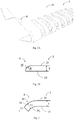
FIG. 5A illustrates a perspective view of a shaving assembly including a protection component constructed as a separate component, in accordance with embodiments of the present disclosure; -
FIG. 5B illustrates a cross-sectional view of a shaving assembly including a protection component ofFIG. 5A ; -
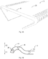
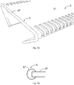
FIG. 6A illustrates a perspective view of a protection element constructed as a sidewall of the supporting member of a shaving assembly, in accordance with embodiments of the present disclosure; -
FIG. 6B illustrates a cross-sectional view of the shaving assembly including the protection element ofFIG. 6A ; and -
FIG. 6C illustrates a perspective view of the shaving assembly including the protection element ofFIG. 6A . - Throughout the drawings, the same or similar reference symbols are used to indicate the same or similar elements.
- Principles of the present disclosure will now be described with reference to several example embodiments shown in the drawings. Though example embodiments of the present disclosure are illustrated in the drawings, it is to be understood that the embodiments are described only to facilitate those skilled in the art in better understanding and thereby achieving the present disclosure, rather than to limit the scope of the disclosure in any manner.
-
FIG. 1A illustrates a perspective view of aconventional shaving assembly 100 in an unassembled status. As shown, the shavingassembly 100 generally includes a supportingmember 1, a cuttingelement 2 extending in a first direction X, and aguard foil 3 also extending in the first direction X. - The
contact surface 31 includes a plurality of guard teeth 37 (also referred to as "hair-catching cut-outs") arranged along the first direction X, and the cuttingelement 2 includes a plurality of movingteeth 21 arranged along the first direction X. In operation, under the control of a driving mechanism (is not shown), the movingteeth 21 are adapted to move (or oscillate) with respect to the plurality ofguard teeth 37 along the first direction X. For sake of discussion, the first direction X may be considered as a longitudinal direction of the shavingassembly 100. -
FIG. 1B illustrates a perspective view of the shavingassembly 100 in an assembled status. As shown, theguard foil 3 is stretched and surrounding the cuttingelement 2 via a bend of a part of theguard foil 3 with respect to an axis along the first direction X. In some embodiments, the thickness of theguard foil 3 is in a range of 40 to 120 micrometers, for example, 80 micrometers. - The
guard foil 3 includes abent part 38 and aflat contact surface 31. Thebent part 38 extends in the first direction X for fixing theguard foil 3 on the supportingmember 1. Theflat contact surface 31 is adapted to be in contact with skin of a user. - In addition to the two lateral sides along the first direction X, as further illustrated in
FIG. 1B , theflat contact surface 31 also includes twoglide edges 39 which are oriented substantially perpendicular to the first direction X and exposed to the user's skin with no protection means provided thereon. As discussed above, in view of the fact that the glide edges 39 are formed by punching or cutting from a thin metal foil, these twoglide edges 39 are usually sharp and not optimal for shaving comfort or safety. - In view of the forgoing, according to various embodiments of the present disclosure, the shaving
assembly 100 as shown inFIGs. 1A-1B is further equipped with a skin-friendly protection element 4. Theprotection element 4 is arranged at theends 310 of theguard foil 3 and includes acurved surface 41 exposed to the skin of the user. In this way, a direct contact of sharp edges with the skin of the user can be avoided, thereby improving the shaving comfort and guaranteeing the shaving safety. - Various embodiments of the shaving
assembly 100 with theprotection element 4 are described below with reference toFIGs. 2A-6C . - In some embodiments, the
protection element 4 and theends 310 of theguard foil 3 can be integrally formed. In other words, theprotection element 4 may be considered as a part of the guard foil. In an example embodiment, as shown inFIGs. 2A-2B , theprotection element 4 may include arounded surface 32 that is transiting from thecontact surface 31 of theguard foil 3 to abottom surface 33 of theguard foil 3.FIG. 2B shows a cross-sectional view of theprotection element 4 along the first direction X. As shown, therounded surface 32 may have a rounding radius R that is larger than or equal to a thickness T of theguard foil 3. - Such an arced edge with a radius approaching the thickness of the guard foil 3 (may also referred to as "a radiused edge") can be achieved, for example, by polishing the edges of the
contact surface 31. The radiused edge does not change the overall flat shape of thecontact surface 31 and only locally changes the profile of the edge in the thickness direction, or in other words, thebottom surface 33 of theguard foil 3 is kept substantially flat. Therefore, the overall stiffness of theguard foil 3 can be well maintained. Moreover, no additional element or part, as well as the simple polishing proceeding, make the protection element cost-effective. - Alternatively, in another example embodiment as shown in
FIG. 3 , theprotection element 4 includes acurved portion 34 transiting from theguard foil 3 and constructed to be gradually curved in a direction away from the skin Y1. In this design, thecurved portion 34 includes a firstcurved surface 341 transiting from thecontact surface 31 of theguard foil 3 and a secondcurved surface 342 transiting from abottom surface 33 of theguard foil 3. - In some embodiments, the
curved portion 34 may have a uniform thickness T1 that is substantially equal to the thickness T of theguard foil 3. In some other embodiments, variation in thickness throughout thecurved portion 34 may be allowed. - Because such
curved portion 34 with a receding edge is allowed to be curved or bent in a large space, the curvature of thecurved portion 34 can be largely adjusted. Thereby enabling high design flexibility. - In yet another example embodiment, the
protection element 4 may include a firstcurved portion 35 and a secondcurved portion 36, and which jointly define thecurved surface 41. For example, as shown inFIGs. 4A-4B , the firstcurved portion 35 is transiting from theguard foil 3 and constructed to be gradually curved in a direction towards the skin Y2, and the secondcurved portion 36 is transiting from the firstcurved portion 35 and constructed to be gradually curved in a direction away from the skin Y1. - In some embodiments, the first
curved portion 35 and the secondcurved portion 36 may have a uniform thickness T2 that is substantially equal to a thickness T of theguard foil 3. In some other embodiments, variation in thickness throughout the firstcurved portion 35 and secondcurved portion 36 may be allowed - In this design, no additional element or part is required, which makes the protection element cost-effective. Moreover, compared to the receding edge as shown in
FIG. 3 , the slight raising of the receding edge creates a small 'bulge', which can help in balancing the bending stress from the side for the main functional bend for theguard teeth 37. Meanwhile, such a small bulge has little to no effect on shaving performance. - In some embodiment as shown
FIGs. 5A-5B , theprotection element 4 can be constructed as a bead made of lacquer or resin and having a roundedprofile 47 surrounding theend 310 of theguard foil 3.Such protection element 4 formed by for example a simple dipping or edge-painting of the sharp edge can provide an effective and low-cost protection solution. Moreover, a sufficient durability for the shaving lifetime of the shavingassembly 100 can be achieved due to the additional protection bead. - In some embodiment as shown
FIGs. 6A-6C , theprotection element 4 is constructed as asidewall 42 of the supportingmember 1. Thesidewall 42 includes thecurved surface 41 projecting beyond thecontact surface 31 in a second direction Y that is substantially perpendicular to the first direction X. It is to be appreciated that theside wall 42 may be integrally formed with the supportingmember 1. Of course, theside wall 42 may also be a separate component that is detachable from the supportingmember 1. In some embodiments, thesidewall 42 may surround theend 310 of theguard foil 3 to completely protect theend 310 of theguard foil 3 from being exposed to the user's skin. - In this way, the original design of the
guard foil 3 is not affected, which eases the fabrication of theguard foil 3. Moreover, such modular components-basedshaving assembly 100 allows manufacturers to individually fabricate all necessary components and store them for a future assembly. In addition, thesidewall 42 may also function as the side cover of the shavingassembly 100 to close the internal space defined by the supportingelement 1 and theguard foil 3 during the hair cutting. In this way, the cut-off hair may be at least temporarily kept within the internal space without going to the ambient. - It is to be understood that the above detailed embodiments of the present disclosure are only to exemplify or explain principles of the present disclosure and not to limit the present disclosure. Therefore, any modifications, equivalent alternatives and improvement, etc. without departing from the spirit and scope of the present disclosure shall be included in the scope of protection of the present disclosure. Meanwhile, appended claims of the present disclosure aim to cover all the variations and modifications falling under the scope and boundary of the claims or equivalents of the scope and boundary.
Claims (10)
- A shaving assembly (100), characterized in comprising:a supporting member (1);a cutting element (2) extending in the first direction (X);a guard foil (3) stretched and extending in the first direction (X) and surrounding the cutting element (2), the guard foil (3) including a bent part (38) and a flat contact surface (31), wherein the bent part (38) extends in the first direction (X) for fixing the guard foil (3) on the supporting member (1), and the flat contact surface (31) is adapted to be in contact with skin; anda protection element (4) arranged at at least one end (310) of the guard foil (3) and including a curved surface (41) exposed to the skin.
- The shaving assembly (100) of claim 1, characterized in that the protection element (4) and the end (310) of the guard foil (3) are integrally formed.
- The shaving assembly (100) of claim 2, characterized in that the protection element (4) includes a rounded surface (32) transiting from the contact surface (31) of the guard foil (3) to a bottom surface (33) of the guard foil (3),
wherein the rounded surface (32) has a rounding radius (R) larger than or equal to a thickness (T) of the guard foil (3). - The shaving assembly (100) of claim 2, characterized in that the protection element (4) includes a curved portion (34) transiting from the guard foil (3) and constructed to be gradually curved in a direction away from the skin (Y1),
wherein the curved portion (34) includes a first curved surface (341) transiting from the contact surface (31) of the guard foil (3) and a second curved surface (342) transiting from a bottom surface (33) of the guard foil (3). - The shaving assembly (100) of claim 2, characterized in that the protection element (4) includes:a first curved portion (35) transiting from the guard foil (3) and constructed to be gradually curved in a direction towards the skin (Y2); anda second curved portion (36) transiting from the first curved portion (35) and constructed to be gradually curved in a direction away from the skin (Y1),wherein the first curved portion (35) and the second curved portion (36) jointly define the curved surface (41).
- The shaving assembly (100) of claim 1, characterized in that the protection element (4) is constructed as a bead made of lacquer or resin and having a rounded profile (47) surrounding the end (310) of the guard foil (3).
- The shaving assembly (100) of claim 1, characterized in that the protection element (4) is constructed as a sidewall (42) of the supporting member (1), wherein the sidewall (42) includes the curved surface (41) projecting beyond the contact surface (31) in a second direction (Y) that is substantially perpendicular to the first direction (X).
- The shaving assembly (100) of claim 7, characterized in that the sidewall (42) surrounds the end (310) of the guard foil (3).
- The shaving assembly (100) of claim 7, characterized in that
the contact surface (31) includes a plurality of guard teeth (37) arranged along the first direction (X); and
the cutting element (2) includes a plurality of moving teeth (21) arranged along the first direction (X) and adapted to move with respect to the plurality of guard teeth (37) along the first direction (X). - A hair cutting appliance, characterized in comprising:a shaving assembly (100) according to any of claims 1-9; anda driving mechanism configured to cause a movement of the cutting element (2) inside the shaving assembly (100).
Priority Applications (9)
| Application Number | Priority Date | Filing Date | Title |
|---|---|---|---|
| EP18171809.9A EP3566829A1 (en) | 2018-05-11 | 2018-05-11 | Shaving assembly and hair cutting appliance |
| RU2020122273A RU2760866C1 (en) | 2017-12-05 | 2018-11-26 | Shaving unit and hair cutting device |
| US16/768,959 US11453137B2 (en) | 2017-12-05 | 2018-11-26 | Shaving assembly and hair cutting appliance |
| PCT/EP2018/082464 WO2019110335A1 (en) | 2017-12-05 | 2018-11-26 | Shaving assembly and hair cutting appliance |
| JP2020530485A JP6818188B1 (en) | 2017-12-05 | 2018-11-26 | Shaving assembly and hair cutting equipment |
| CN201880079106.1A CN111788047A (en) | 2018-05-11 | 2018-11-26 | Shaving assembly and hair cutting appliance |
| ES18807332T ES2897535T3 (en) | 2017-12-05 | 2018-11-26 | Shaving set and hair cutting device |
| EP18807332.4A EP3720669B1 (en) | 2017-12-05 | 2018-11-26 | Shaving assembly and hair cutting appliance |
| EP21164594.0A EP3871845A1 (en) | 2017-12-05 | 2018-11-26 | Shaving assembly and hair cutting appliance |
Applications Claiming Priority (1)
| Application Number | Priority Date | Filing Date | Title |
|---|---|---|---|
| EP18171809.9A EP3566829A1 (en) | 2018-05-11 | 2018-05-11 | Shaving assembly and hair cutting appliance |
Publications (1)
| Publication Number | Publication Date |
|---|---|
| EP3566829A1 true EP3566829A1 (en) | 2019-11-13 |
Family
ID=62152437
Family Applications (1)
| Application Number | Title | Priority Date | Filing Date |
|---|---|---|---|
| EP18171809.9A Withdrawn EP3566829A1 (en) | 2017-12-05 | 2018-05-11 | Shaving assembly and hair cutting appliance |
Country Status (2)
| Country | Link |
|---|---|
| EP (1) | EP3566829A1 (en) |
| CN (1) | CN111788047A (en) |
Citations (5)
| Publication number | Priority date | Publication date | Assignee | Title |
|---|---|---|---|---|
| US2323655A (en) * | 1939-10-16 | 1943-07-06 | Gillette Safety Razor Co | Mount for shearing heads |
| EP2875917A1 (en) * | 2013-11-22 | 2015-05-27 | Koninklijke Philips N.V. | Hair cutting appliance and blade set |
| US20150314461A1 (en) * | 2014-05-02 | 2015-11-05 | Raymond Industrial Ltd. | Hybrid Shaving System |
| WO2016134979A1 (en) * | 2015-02-25 | 2016-09-01 | Koninklijke Philips N.V. | Stationary blade, blade set, and hair cutting appliance |
| CN106346519A (en) | 2016-10-12 | 2017-01-25 | 吴让攀 | Reciprocating type electric shaver head |
-
2018
- 2018-05-11 EP EP18171809.9A patent/EP3566829A1/en not_active Withdrawn
- 2018-11-26 CN CN201880079106.1A patent/CN111788047A/en active Pending
Patent Citations (5)
| Publication number | Priority date | Publication date | Assignee | Title |
|---|---|---|---|---|
| US2323655A (en) * | 1939-10-16 | 1943-07-06 | Gillette Safety Razor Co | Mount for shearing heads |
| EP2875917A1 (en) * | 2013-11-22 | 2015-05-27 | Koninklijke Philips N.V. | Hair cutting appliance and blade set |
| US20150314461A1 (en) * | 2014-05-02 | 2015-11-05 | Raymond Industrial Ltd. | Hybrid Shaving System |
| WO2016134979A1 (en) * | 2015-02-25 | 2016-09-01 | Koninklijke Philips N.V. | Stationary blade, blade set, and hair cutting appliance |
| CN106346519A (en) | 2016-10-12 | 2017-01-25 | 吴让攀 | Reciprocating type electric shaver head |
Also Published As
| Publication number | Publication date |
|---|---|
| CN111788047A (en) | 2020-10-16 |
Similar Documents
| Publication | Publication Date | Title |
|---|---|---|
| EP3720669B1 (en) | Shaving assembly and hair cutting appliance | |
| CN207824944U (en) | Shaving component and hair cutter | |
| CN109079862B (en) | Hair cutting system and accessory | |
| JP6395848B2 (en) | Shaving blade cartridge, shaver comprising such a shaving blade cartridge, and method of manufacturing such a shaving blade cartridge | |
| ES2681270T3 (en) | Haircutting apparatus and blade set | |
| EP3768476B1 (en) | Shaving assembly and hair cutting appliance | |
| EP3209469B1 (en) | A shaving blade cartridge and a shaver comprising such shaving blade cartridge | |
| EP3134235B1 (en) | Razor cartridge guards | |
| US20170136639A1 (en) | Razor cartridge and razor using same | |
| US10369712B2 (en) | Shaving blade cartridge and a shaver comprising such shaving blade cartridge | |
| EP3566829A1 (en) | Shaving assembly and hair cutting appliance | |
| US9399303B2 (en) | Hair trimmer with curved blade | |
| EP3566830A1 (en) | Shaving assembly and hair cutting appliance | |
| EP3175959B1 (en) | Razor having attached shaving aid | |
| KR101409411B1 (en) | Razor |
Legal Events
| Date | Code | Title | Description |
|---|---|---|---|
| PUAI | Public reference made under article 153(3) epc to a published international application that has entered the european phase |
Free format text: ORIGINAL CODE: 0009012 |
|
| AK | Designated contracting states |
Kind code of ref document: A1 Designated state(s): AL AT BE BG CH CY CZ DE DK EE ES FI FR GB GR HR HU IE IS IT LI LT LU LV MC MK MT NL NO PL PT RO RS SE SI SK SM TR |
|
| AX | Request for extension of the european patent |
Extension state: BA ME |
|
| RAP1 | Party data changed (applicant data changed or rights of an application transferred) |
Owner name: KONINKLIJKE PHILIPS N.V. |
|
| STAA | Information on the status of an ep patent application or granted ep patent |
Free format text: STATUS: THE APPLICATION IS DEEMED TO BE WITHDRAWN |
|
| 18D | Application deemed to be withdrawn |
Effective date: 20200603 |